

McIntosh MR-87 Owners Manual
McIntosh Laboratory, Inc. 2 Chambers Street Binghamton, New York 13903-2699 Phone: 607-723-3512 www mcintoshlabs.com
MR87
AM/FM Tuner
Owner’s Manual
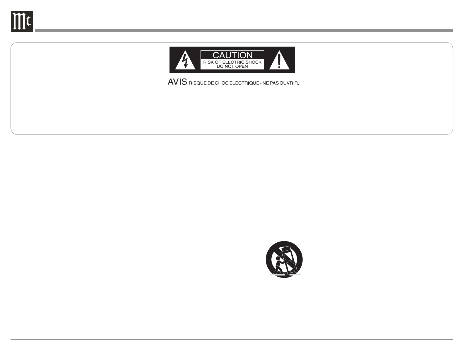
The lightning ash with arrowhead, within an equilateral
triangle, is intended to alert the user to the presence of
uninsulated “dangerous voltage” within the product’s enclosure that may be of sufcient magnitude to constitute
a risk of electric shock to persons.
The exclamation point within an equilateral triangle is
intended to alert the user to the presence of important
operating and maintenance (servicing) instructions in the
literature accompanying the appliance.
WARNING - TO REDUCE RISK
OF FIRE OR ELECTRICAL
SHOCK, DO NOT EXPOSE
THIS EQUIPMENT TO RAIN OR
MOISTURE.
IMPORTANT SAFETY
INSTRUCTIONS!
PLEASE READ THEM BEFORE
OPERATING THIS EQUIPMENT.
1. Read these instructions.
2. Keep these instructions.
3. Heed all warnings.
4. Follow all instructions.
5. Do not use this apparatus near water.
6. Clean only with a dry cloth.
7. Do not block any ventilation openings. Install
in accordance with the manufacturer’s instructions.
8. Do not install near any heat sources such as
radiators, heat registers, stoves, or other appa-
ratus (including ampliers) that produce heat.
9. Do not defeat the safety purpose of the polarized or grounding-type plug. A polarized plug
has two blades with one wider than the other.
A grounding type plug has two blades and a
NO USER-SERVICEABLE PARTS
INSIDE. REFER SERVICING TO
QUALIFIED PERSONNEL.
third grounding prong. The wide blade or the
third prong are provided for your safety. If
the provided plug does not t into your outlet,
consult an electrician for replacement of the
obsolete outlet.
10. Protect the power cord from being walked on
or pinched particularly at plugs, convenience
receptacles, and the point where they exit
from the apparatus.
11. Only use attachments/accessories specied by
the manufacturer.
12. Use only with the cart, stand, tripod, bracket,
or table specied by the manufacturer, or sold with the apparatus. When a cart is used, use
caution when moving the cart/
apparatus combination to avoid
injury from tip-over.
13. Unplug this apparatus during lightning storms
or when unused for long periods of time.
14. Refer all servicing to qualied service personnel. Servicing is required when the apparatus
has been damaged in any way, such as power-
To prevent the risk of electric
shock, do not remove cover or
back. No user-serviceable parts
inside.
supply cord or plug is damaged, liquid has
been spilled or objects have fallen into the
apparatus, the apparatus has been exposed to
rain or moisture, does not operate normally, or
has been dropped.
15. Do not expose this equipment to dripping or
splashing and ensure that no objects lled
with liquids, such as vases, are placed on the
equipment.
16. To completely disconnect this equipment from
the a.c. mains, disconnect the power supply
cord plug from the a.c. receptacle.
17. The mains plug of the power supply cord shall
remain readily operable.
18. Do not expose batteries to excessive heat such
as sunshine, re or the like.
19. Connect mains power supply cord only to a
mains socket outlet with a protective earthing
connection.
2
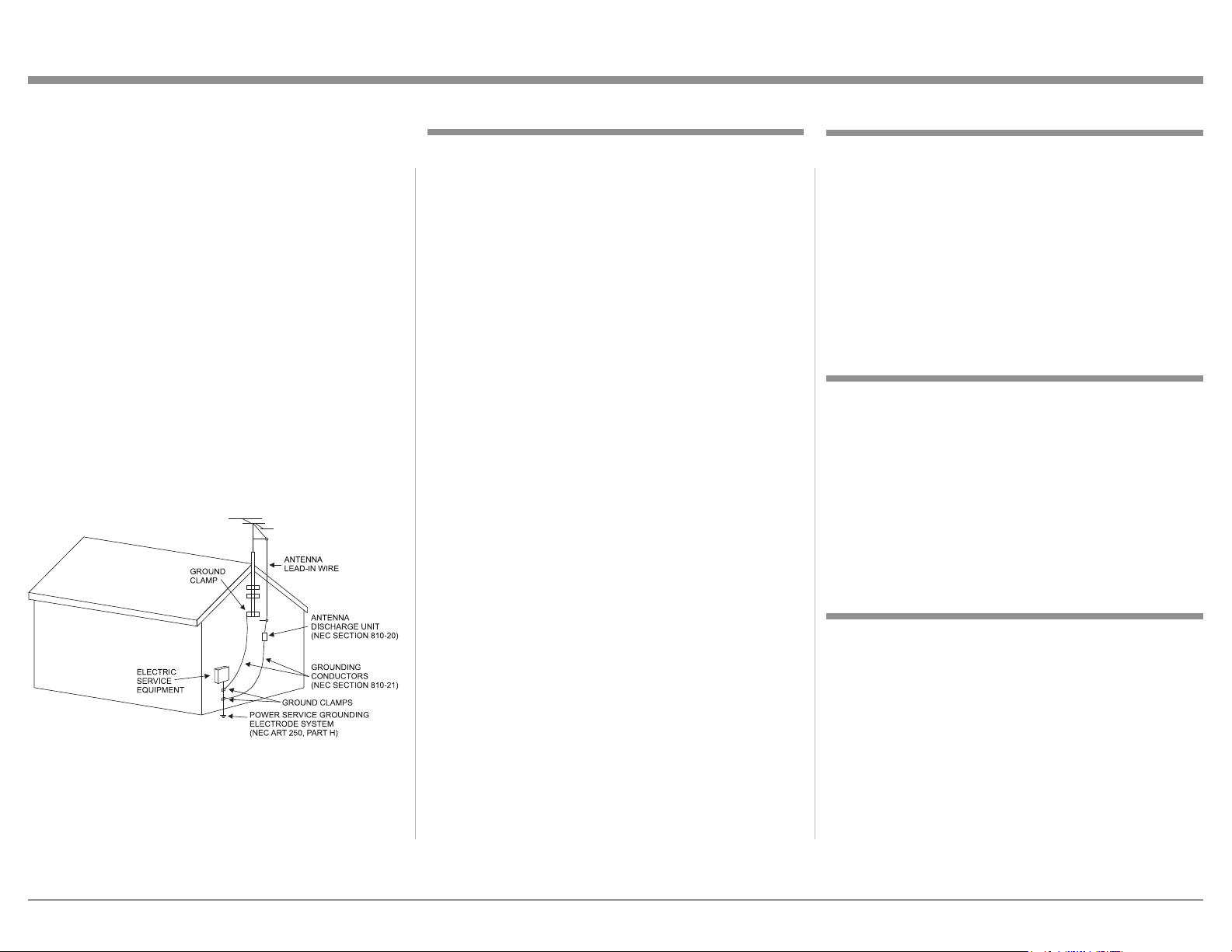
Outdoor Antenna Grounding
If an outside antenna or cable system is connected
to the product, be sure the antenna or cable system is grounded so as to provide some protection
against voltage surges and built-up static charge.
Article 810 of the National Electrical Code, ANSI/
NFPA 70, provides information with reguards
to proper grounding of the mast and supporting
structure, grounding of the lead-in wire to an antenna discharge unit, and size of ground conductors, location of antenna-discharge unit, connection to ground electrodes and requirements for the
grounding electrode.
Example of antenna grounding as per
National Electrical Code,
ANSI/NFPA 70
Table of Contents
Safety Instructions ..................................................2-3
Table of Contents ....................................................... 3
Thank You and Please Take a Moment ...................... 3
Technical Assistance .................................................. 3
Customer Service and General Information .............. 4
Connector and Cable Information .............................4
Introduction ................................................................ 5
Performance Features ................................................ 5
Dimensions ................................................................6
Installation .................................................................7
Connections:
Rear Panel and RAA2 Connections .......................... 8
How to Connect Antennas ......................................... 9
How to Connect the MR87 ................................. 10 -11
Remote Control:
Remote Control Push-buttons .................................. 12
How to use the Remote Control ............................... 13
Thank You
Your decision to own this McIntosh MR87 AM/FM
Tuner ranks you at the very top among discriminating
music listeners. You now have “The Best.” The McIntosh dedication to “Quality,” is assurance that you will
receive many years of musical enjoyment from this
unit.
Please take a short time to read the information in
this manual. We want you to be as familiar as possible with all the features and functions of your new
McIntosh.
Please Take A Moment
The serial number, purchase date and McIntosh Dealer
name are important to you for possible insurance
claim or future service. The spaces below have been
provided for you to record that information:
Serial Number: _______________________________
Purchase Date: _______________________________
Front Panel and Setup:
Front Panel Displays, Controls and Push-buttons .... 14
Setup ................................................................... 15-19
Operation:
How to Operate the MR87 ..................................20 -23
Additional Information:
Photos .................................................................. 24-25
Specifications ........................................................... 26
Packing Instruction .................................................. 27
Copyright 2009 © by McIntosh Laboratory, Inc.
Dealer Name: ________________________________
Technical Assistance
If at any time you have questions about your McIntosh
product, contact your McIntosh Dealer who is familiar
with your McIntosh equipment and any other brands
that may be part of your system. If you or your Dealer
wish additional help concerning a suspected problem,
you can receive technical assistance for all McIntosh
products at:
McIntosh Laboratory, Inc.
2 Chambers Street
Binghamton, New York 13903
Phone: 607-723-3512
Fax: 607-724-0549
3
Customer Service
Power
Control
Ground
N/C
Data
Signal
N/C
Data
Ground
IR Data
Control
Ground
N/C
Pin 1
Pin 1
Pin 8
Pin 8
*Cable outer shield
PIN 1
PIN 2
PIN 3
If it is determined that your McIntosh product is in
need of repair, you can return it to your Dealer. You
can also return it to the McIntosh Laboratory Service
Department. For assistance on factory repair return
procedure, contact the McIntosh Service Department
at:
McIntosh Laboratory, Inc.
2 Chambers Street
Binghamton, New York 13903
Phone: 607-723-3515
Fax: 607-723-1917
General Information
1. For additional connection information, refer to the
owner’s manual(s) for any component(s) connected
to the MR87 AM/FM Tuner.
2. The Main AC Power going to the MR87 and any
other McIntosh Component(s) should not be applied
until all the system components are connected
together. Failure to do so could result in malfunctioning of some or all of the system’s normal operations. When the MR87 and other McIntosh Components are in their Standby Power Off Mode, the
Microprocessor’s Circuitry inside each component
is active and communication is occurring between
them.
3. The Balanced and Unbalanced Outputs may be
used simultaneously.
4. The Remote Control Supplied with the MR87
Tuner is capable of operating other components. For
additional information go to www.mcintoshlabs.
com.
5. When discarding the unit, comply with local rules
or regulations. Batteries should never be thrown
away or incinerated but disposed of in accordance
4
with the local regulations concerning battery disposal.
7. For additional information on the MR87
and other McIntosh Products please visit
the McIntosh Web Site at www.mcintoshlabs.com.
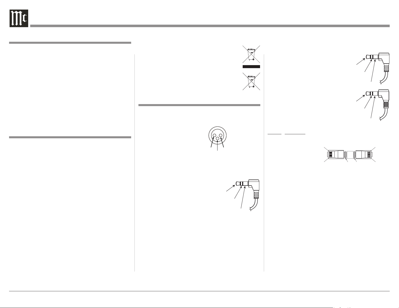
Connector and Cable Information
XLR Connectors
Below is the Pin configuration for the XLR Balanced
Output Connectors on the MR87. Refer to the diagrams for connections:
PIN 1: Shield/Ground
PIN 2: + Signal
PIN 3: - Signal
Power Control Connectors
The MR87 Power Control Input/Output Jacks receive/
send Power On/Off Signals when connected to other
McIntosh Components. A 1/8
inch stereo mini phone plug
is used for connection to the
Power Control Input/Output on
the MR87.
Note: The Data and Power
Control Connecting Cable is available from the
McIntosh Parts Department:
Data and Power Control Cable Part No. 170-202
Six foot, shielded 2 conductor, with 1/8 inch stereo
mini phone plugs on each end.
Data and IR Input Port Connectors
The MR87 Data In Port receives
Remote Control Signals. A 1/8
inch stereo mini phone plug is
used for connection. The IR Port
also use a 1/8 inch stereo mini
phone plug and allow the connection of other brand IR Receivers
to the MR87.
RAA2 Connectors
Pin No. Wire Color
1. White/Orange
2. Orange
3. White/Green
4. Blue
5. White/Blue
6. Green
7. W hite /Br own
8. Brown
*Cable outer shield
Note: The RAA2 Connecting Cable is available from the
McIntosh Parts Department:
RAA2 Antenna Cable Part No. 171844
Twenty foot, shielded 8 conductor, with a shielded
RJ45 connector on each end.

Introduction
The MR87 AM/FM Tuner is an elegant instrument
for superb reception from Radio Stations. The MR87
uses the latest in technology for the best sound quality,
along with the convenient operation of a Dial Glass
with Tuning Pointer used in classic McIntosh Analog
Tu ne rs.
Performance Features
• Special FM RF Circuitry
The MR87 RF Circuitry receives strong local FM Station Signals without distortion and receives even the
weakest of FM Signals with low noise.
General Information, Cable Information, Introduction and Performance Features
• Digital Audio Outputs
There are Coaxial and Optical Digital Outputs for
external decoding of the PCM Signal.
• Multifunction Fluorescent Display
The Front Panel Display indicates various setup and
tuner functions.
• Information Service
The MR87 will indicate various text information such
as Station Call Sign, Music Genre, Artist Name and
Song Title when transmitted by the Radio Station.
• Fiber Optic Solid State Front Panel Illumination
The even Illumination of the Front Panel is accomplished by the combination of custom designed Fiber
Optic Light Diffusers and extra long life Light Emit-
ting Diodes (LEDs).
• Glass Front Panel and Super Mirror
Chassis Finish
The famous McIntosh Illuminated Glass Front Panel
and the Stainless Steel Chassis with Super Mirror
Finish ensures the pristine beauty of the MR87 will be
retained for many years.
• RAA2 External AM Antenna
The RAA2 External AM Antenna allows placement
of the AM Antenna for the best reception.
• Preset Stations and Permanent Memory
The MR87 Tuner stores up to twenty AM and FM
Station presets and they are retained in Permanent
Me mor y.
• Flywheel Tuning and Electronic Dial Pointer
The Smooth Acting Weighted Tuning mechanism with
Glass Dial and Illuminated Electronic Pointer recall
the classic McIntosh tuner designs of the 60’s and
70’s while a full complement of RS232 control with
metadata support makes the MR87 the go-to multiformat broadcast audio source for today’s whole-house
systems.
• Balanced Outputs
The Balanced Outputs allow connection of the MR87
to a Preamplifier using long cable lengths without a
loss in sound quality.
• Remote Control with External Sensor Input
The Remote Control provides control of the MR87 operating functions and other McIntosh Source Components. Enjoy your McIntosh System from other rooms
in your home by connecting external sensors.
• Power Control Output and Trigger Assignment
A Power Control connection for convenient Turn-On
of McIntosh Power Components and Accessories is
included.
• Special Power Supply
Fully regulated Power Supplies and a special R-Core
Power Transformer ensure stable noise free operation
even though the power line varies.
• Gold Plated Connectors
The MR87 Digital and Analog Audio Connectors are
gold plated for superior corrosion resistance and high
electrical conductivity.
5
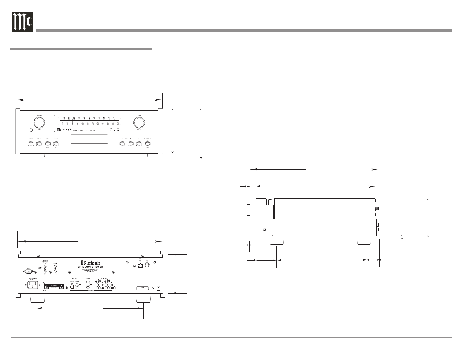
Dimensions
P1 91.5 MHz ST
Pink Floyd: Money
Side View of the MR87
Front View of the MR87
Rear View of the MR87
17-1/2"
44.45cm
6"
15.24cm
5-3/8"
13.69cm
4-5/8"
11.75cm
13-1/4"
33.65cm
17"
43.18cm
14-1/2"
36.83cm
15-7/8"
40.32cm
3/16"
0.48cm
4-13/16"
12.22cm
10-9/16"
26.83cm
5/8"
1.59cm
13/16"
2.06cm
2"
5.08cm
1-15/16"
4.92cm
The following dimensions can assist in determining
the best location for your MR87.
Dimensions
6
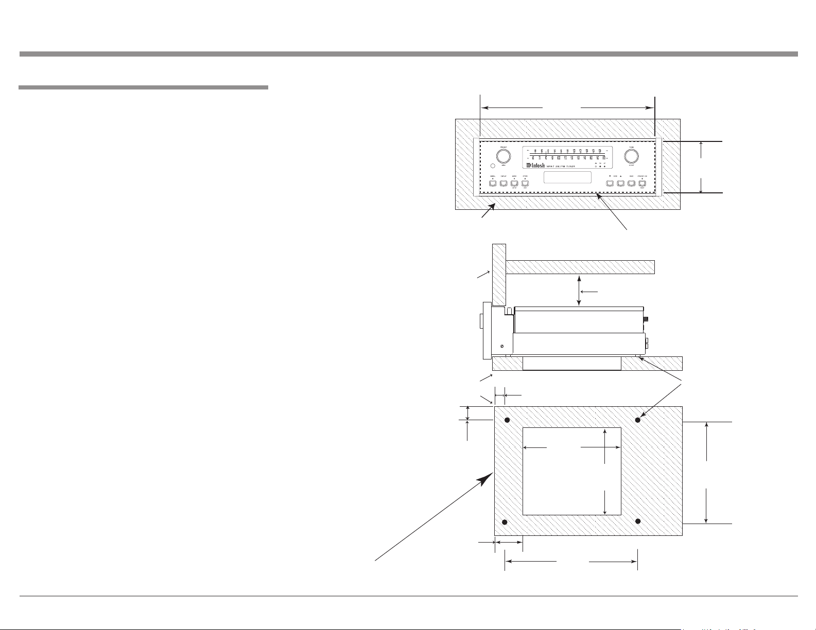
Installation
11"
27.94cm
15"
38.1cm
15"
38.1cm
1"
2.54cm
Cutout Opening
for Ventilation
Cutout Opening for Ventilation
Support
Shelf
Chassis
Spacers
MR87 Side View
in Custom Cabinet
MR87 Bottom View
in Custom Cabinet
1-1/8"
2.86cm
12-5/16"
31.27cm
1-3/4"
4.45cm
Note: Center the cutout Horizontally on the unit.
For purposes of clarity, the above
illustration is not drawn to scale.
Cabinet
Front
Panel
MR87 Front Panel
Custom Cabinet Cutout
17-1/16"
43.34cm
Cutout Opening for Custom Mounting
Cabinet Front Panel
P1 91.5 z ST
Pink Floyd: oney
4-7/8"
12.38cm
2"
5.08cm
Custom Cabinet has
an open back and at
least 12” (30.48cm)
away from any surface
such as a wall
The MR87 can be placed upright on a table or shelf,
standing on its four feet. It also can be custom installed in a piece of furniture or cabinet of your
choice. The four feet may be removed from the bottom
of the MR87 when it is custom installed as outlined
below. The four feet together with the mounting
screws should be retained for possible future use if the
MR87 is removed from the custom installation and
used free standing. The required panel cutout, ventilation cutout and unit dimensions are shown.
Always provide adequate ventilation for your
MR87. Cool operation ensures the longest possible
operating life for any electronic instrument. Do not
install the MR87 directly above a heat generating
component such as a high powered amplifier. If all
the components are installed in a single cabinet, a
quiet running ventilation fan can be a definite asset in
maintaining all the system components at the coolest
possible operating temperature.
When the MR87 is placed free-standing on a flat
surface, allow at least 2 inches (5.08cm) above the
top, 2 inches (5.08cm) below the bottom and 2 inches
(5.08cm) on each side of the Tuner, so airflow is not
obstructed. Allow 19-1/2 inches (49.53cm) depth
behind the front panel. Allow 1-7/16 inch (3.66cm) in
front of the mounting panel for knob clearance.
A custom cabinet installation should provide the
minimum spacing dimensions for cool operation. Al-
low at least 2 inches (5.08cm) above the top, 2 inches
(5.08cm) below the bottom and 2 inches (5.08cm) on
each side of the Tuner, so airflow is not obstructed.
The Custom Cabinet should be open backed and at
least 12 inches (30.48cm) away from any surface such
as a wall. Be sure to cut out a ventilation hole in the
mounting shelf according to the dimensions in the
drawing. Allow 1-7/16 inch (3.66cm) in front of the
mounting panel for knob clearance.
Installation
7
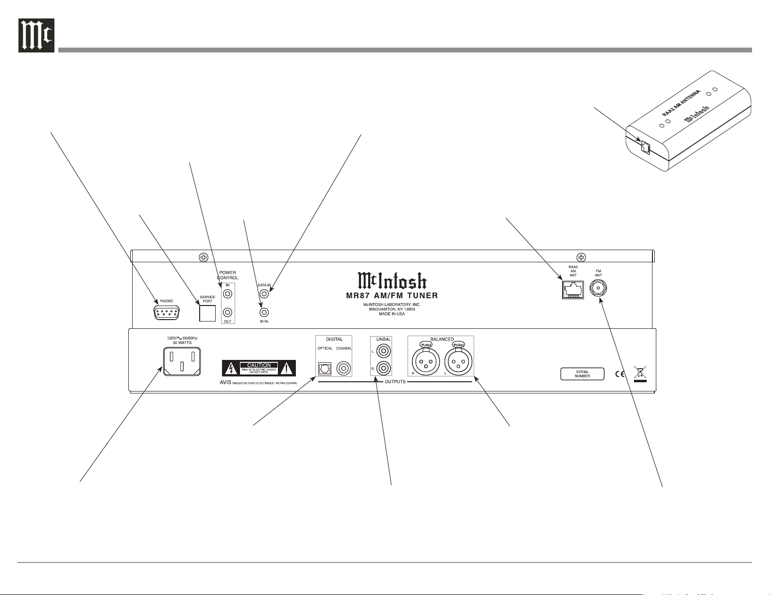
Rear Panel and RAA2 Connections
RS232 connector
for communications with an
external control
device
POWER CONTROL IN receives signals
from a McIntosh component (5-15 Volts
ON, 0 Volts OFF).
POWER CONTROL OUT sends out (12
Volts ON) signal to another McIntosh
Component when the MR87 is On.
Used for upgrading the MR87
Fir mware
IR INput for
connecting an IR
Receiver
DATA IN receives
operating data from a
McIntosh Preamplifier
or Control Center
Connect to the RAA2 AM
ANT connector on MR87
using the supplied cable
AM ANT (Antenna) connector allows a McIntosh
RAA2 Remote Antenna
to be connected
Connect the MR87 power cord to a
live AC outlet. Refer to information
on the back panel of your MR87 to
determine the correct voltage for
your unit
8
COAXIAL AND OPTICAL
DIGITAL AUDIO OUTPUTS
send signals to a Preamplifier
or Control Center with a D/A
Converter or a decoder
BALANCED AUDIO OUTPUTS
supply analog audio signals to
Balanced Inputs of other components
UNBALANCED AUDIO OUTPUTS
supply analog audio signals to Unbalanced Inputs of other components
75 OHM FM ANT
(Antenna) connects
to an external FM
Antenna or cable
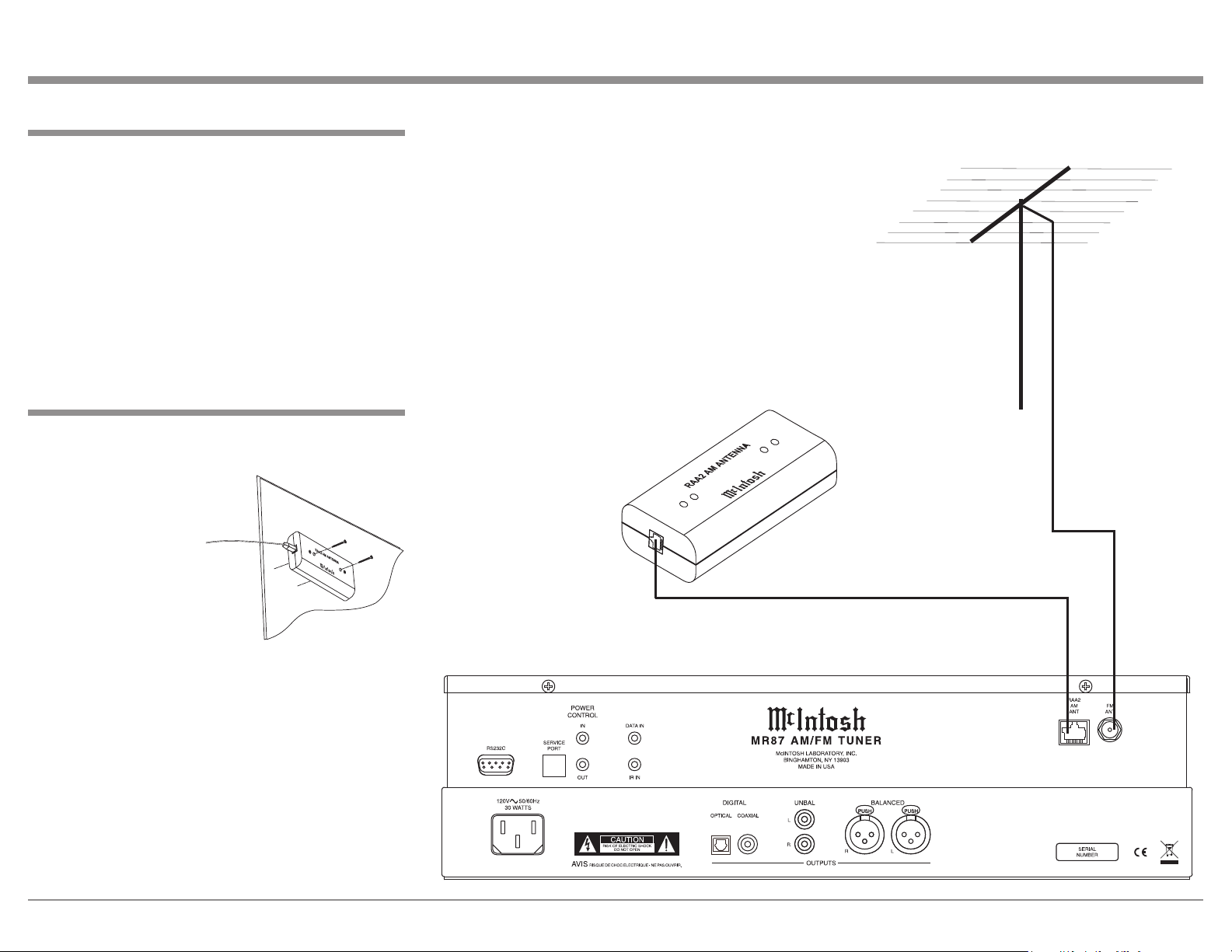
How to Connect Antenna Components
1. Using the supplied shielded cable, connect one end
into the RAA2 AM Antenna jack and the other
end of the same cable into the MR87 Tuner jack
labeled RAA2 AM ANT.
Note: If a longer length cable needs to be used between
the MR87 and the RAA2 AM Antenna, use an 8
conductor straight-thru cable with an outer shield
and RJ45 connectors on each end (shielded CAT5,
CAT5e or CAT6 patch cable).
2. Connect a 75 ohm coax cable from a FM Antenna
or cable system to the MR87, 75 OHM FM ANT
Connector.
Mounting the RAA2 AM Antenna
Tune to a station with the weakest signal and orient the
RAA2 Antenna for maximum signal with minimum
noise and distortion. After the location is determined,
the RAA2 AM Antenna
may be secured to a
suitable surface by using
two #6 1-3/4 to 2 inches
(4.44 to 5.08cm) long
screws, refer to the illustration to the right.
How to Connect Antennas
FM Antenna
9
 Loading...