

McIntosh MP1100 Owner's Manual
McIntosh Laboratory, Inc. 2 Chambers Street Binghamton, New York 13903-2699 Phone: 607-723-3512 www.mcintoshlabs.com
MP1100
Phono Preamplifier
Owner’s Manual

Important Safety Information is supplied in a separate document “Important Additional Operation Information Guide”
Thank You
Your decision to own this McIntosh MP1100 Phono
Preamplifier ranks you at the very top among discriminating music listeners. You now have “The Best.”
The McIntosh dedication to “Quality,” is assurance
that you will receive many years of musical enjoyment
from this unit.
Please take a short time to read the information in
this manual. We want you to be as familiar as possible with all the features and functions of your new
McIntosh.
Please Take A Moment
The serial number, purchase date and McIntosh Dealer
name are important to you for possible insurance
claim or future service. The spaces below have been
provided for you to record that information:
Serial Number: _______________________________
Purchase Date: _______________________________
Dealer Name: ________________________________
Technical Assistance
If at any time you have questions about your McIntosh
product, contact your McIntosh Dealer who is familiar
with your McIntosh equipment and any other brands
that may be part of your system. If you or your Dealer
wish additional help concerning a suspected problem,
you can receive technical assistance for all McIntosh
products at:
McIntosh Laboratory, Inc.
2 Chambers Street
Binghamton, New York 13903
Phone: 607-723 -3512
Fax: 607-724-0549
Customer Service
If it is determined that your McIntosh product is in
need of repair, you can return it to your Dealer. You
can also return it to the McIntosh Laboratory Service
Department. For assistance on factory repair return
procedure, contact the McIntosh Service Department
at:
McIntosh Laboratory, Inc.
2 Chambers Street
Binghamton, New York 13903
Phone: 607-723 -3515
Fax: 607-723-1917
Table of Contents
Safety Instructions ..................................................... 2
(Separate Sheet) ................... Important Additional
Operation Information Guide
Thank You and Please Take a Moment ...................... 2
Technical Assistance and Customer Service ............. 2
Table of Contents ....................................................... 2
General Information .................................................. 3
Connector and Cable Information ............................. 3
Introduction ................................................................ 4
Performance Features ............................................. 4-5
Dimensions ................................................................ 6
Installation ................................................................. 7
Connections:
Rear Panel Connections .............................................. 8
Connecting Components ............................................. 9
Front Panel:
Front Panel Displays, Controls, Push-buttons .......... 10
Front Panel Information Displays Modes ..................11
Remote Control:
HR090 Remote Control Push-buttons ...................... 12
Setup:
How to Operate the Setup Mode .............................. 13
Default Settings, Firmware Version .......................... 13
Input Settings ....................................................... 13-14
Rename Input ............................................................ 14
Profile Store .............................................................. 15
Digital Output ........................................................... 16
Tube Lights ............................................................... 16
Power Mode .............................................................. 16
IR Sensor................................................................... 17
Factory Reset ............................................................ 17
Operation:
How to Operate the MP1100 ................................ 18-23
Trim Functions ..................................................... 18 -22
Mute, Trim and Output Meters ................................. 23
USB Input and Installing Software ...................... 24-26
Reset of Microprocessors .......................................... 25
Graphic Curves .................................................... 27-28
Rumble and Scratch Filter Curves ............................ 28
Additional Information:
Photo ......................................................................... 29
Specifications ............................................................ 30
Packing Instruction ................................................... 31
Copyright 2016 © by McIntosh Laboratory, Inc.
2
General Information and Connector Information
General Information
1. For additional connection information, refer to the
owner’s manual(s) for any component(s) connected
to the MP1100 Phono Preamplifier.
2. The Main AC Power going to the MP1100 and any
other McIntosh Component(s) should not be applied
until all the system components are connected
together. Failure to do so could result in malfunctioning of some or all of the system’s normal
operations. When the MP1100 and other McIntosh
Components are in their Standby Power Off Mode,
the Microprocessor’s Circuitry inside each component is active and communication is occurring
between them.
3. The Balanced and Unbalanced Outputs may be
used simultaneously, connected to different Preamplifiers or component recording device.
4. The MP1100 internal Analog to Digital Converter
Circuitry is designed to encode 2-channel PCM
(Pulse Code Modulation) Digital Signals. The
Coaxial and Optical Digital Audio Outputs are for
PCM Digital Signals.
5. Sound Intensity is measured in units called Deci-
bels and “dB” is the abbreviation.
6. When discarding the unit, comply with local rules
or regulations. Batteries should never be
thrown away or incinerated but disposed
of in accordance with the local regulations
concerning battery disposal.
7. For additional information on the MP1100
and other McIntosh Products please visit the McIntosh Web Site at www.mcintoshlabs.com.
Connector and Cable Information
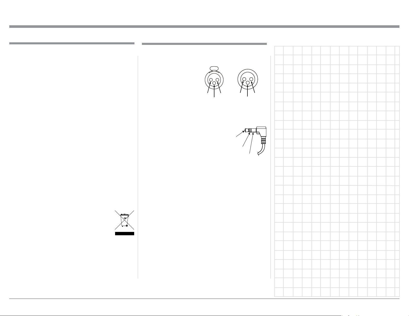
XLR Connectors
Below is the Pin configuration for the XLR Balanced
Output Connector on the MP1100. Refer to the diagram for connections:
PIN 1: Shield/Ground
PIN 2: + Output
PIN 3: - Output
PIN 2 PIN 1
PIN 3
Power Control (Trigger) Connectors
When the MP1100 TRIGger IN Connector receives a
Power Control On Signal (5 to 12 volts) it will make
that signal available at the TRIGger OUT Connector to control
other connected McIntosh Components. An additional connection
is for controlling the illumination
of the Output Meters on McIntosh
Components. A 3.5mm stereo mini phone plug is used
for connection to the Power Control (Trigger) Connectors on the MP1100.
PIN 1
Power
Control
Meter
Illumination
Control
PIN 3
Ground
PIN 2
3

Introduction
The McIntosh MP1100 Phono Preamplifier is one of
the finest Phono Preamplifiers ever created and has
the ability for connections to components with analog
and digital inputs. The MP1100 reproduction is sonically transparent and absolutely accurate. The McIntosh Sound is “The Sound of the Music Itself.”
Performance Features
• Electromagnetic Input Switching
Digital Logic Circuits drive Electromagnetic Switches
on Inputs and operating functions for reliable, noiseless, distortion free switching.
• Selectable Phono Cartridge Loading
Adjustable Capacitance and Resistance Loading are
available for both Moving Coil and Moving Magnet
Phono Cartridges. Resistance Loading is selectable
from values of 25 ohms to 47,000 ohms. Capacitance
Loading is selectable from values of 50 picofarads to
400 picofarads.
• Balanced and Unbalanced Outputs
The Balanced Outputs allow connection using long
cable lengths without a loss in sound quality. The
MP1100 also has unbalanced Output connections for
compatibility with a wide range of audio components.
• Dual Mono Design
The circuitry for both channels is totally separate,
physically isolated and shielded which helps to assure
total channel isolation.
• Selectable Equalizer
In addition to normal RIAA Equalization Standard,
the MP1100 provides the ability to select four alternative Equalization Settings of LP, AES, NAB or 78.
This helps to assure a desired tonal balance when
playing a wide variety of phonograph records made
before the RIAA Equalization Standard was employed.
• Vacuum Tube Phono Amplification
The MP1100 utilizes Vacuum Tube Amplification
Circuitry for the Phono Inputs. The circuits use the
latest designs providing the lowest possible noise and
distortion.
• Fully Balanced Circuitry
The MP1100 utilizes the very latest in Fully Balanced
Circuitry from the Input Connectors all the way to the
Output Connectors for the lowest possible noise and
distortion.
• Moving Coil and Moving Magnet Phono Inputs
The MP1100 has three precision Phono Preamplifier
Circuits with unbalanced and balanced connections.
They have the ability to be configured for Moving
Coil or Moving Magnet Cartridges. The close tolerance resistors and capacitors used in the Equalization Circuitry provide an extremely flat frequency
response.
• Rumble and Scratch Filters
Selectable Rumble and Scratch Filters can improve the
quality of sound when playing back older vinyl recodings.
• Digital Audio Outputs
The Digital Outputs encode PCM Signals from the
selected Input (Phono and Line). Coaxial and Optical
Outputs process Digital Signals at 96kHz or 192kHz
with 24-Bit resolution. The Digital Outputs have two
different output level settings and the Digital Circuitry
can be switched Off providing true analog only signal
processing.
• USB Digital Audio Output
The USB Digital Output provides Digital Signals at
96kHz or 192kHz with 24-Bit resolution from the
selected Input.
• Alphanumeric Fluorescent Display
The Front Panel Information Display indicates the
Source Selection, Cartridge Loading, Equalizer and
Setup Mode Selections. The display intensity is adjustable.
• Illuminated Output Meters
The Illuminated Output Meters are peak responding,
and indicate the output of the MP1100 Phono Preamplifier.
• Special Power Supply
The Multi Regulated Power Supply and a special
R-Core Power Transformer ensure stable noise free
operation even though the power line varies.
• Remote Control with External Sensor Input
The Remote Control provides control of the MP1100
operating functions. The External Sensor Input provides Remote Control when the MP1100 is located
behind closed doors or in another room.
4

• Power Control Connections
The Power Control (PWR CTRL) TRIGger INput
Connection provides convenient Turn-On/Off of the
MP1100 when connected to a McIntosh Component
with Power Control TRIGger OUT. The MP1100
TRIGger OUT Connection provides Turn-On/Off
operation when connected with other McIntosh Audio
Components.
• LED Front Panel Illumination
The even Illumination of the Front Panel is accomplished by multiple extra long life Light Emitting
Diodes (LEDs) arranged with a special orientation.
• Glass Front Panel and Super Mirror Chassis
Finish
The famous McIntosh Illuminated Glass Front Panel
and the Lower Chassis are Stainless Steel with a
Mirror Finish. The Upper Chassis and Top Cover is
hairline brushed black Titanium Stainless Steel Finish.
This will ensure the pristine beauty of the MP1100
will be retained for many years to come.
Introduction and Performance Features
5
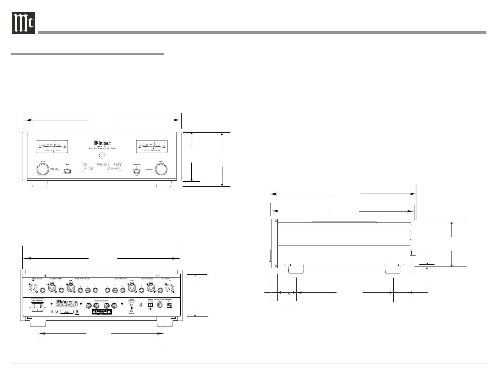
Dimensions
The following dimensions can assist in determining
the best location for your MP1100. There is additional
information on the next page pertaining to installing
the MP1100 into cabinets.
Front View of the MP1100
17-1/2"
44.4cm
Dimensions
Rear View of the MP1100
17-1/8"
43.5cm
13 -1/4"
33.7cm
5-3/8"
13.7cm
4-5/8"
11.8cm
6"
15.2cm
13/16"
2.1cm
2"
5.1cm
Side View of the MP1100
15-7/8"
40.3cm
14-1/2"
36.8cm
10-9/16"
26.8cm
3/16"
0.48cm
1-15/16"
4.9cm
4-13/16"
12.22cm
6
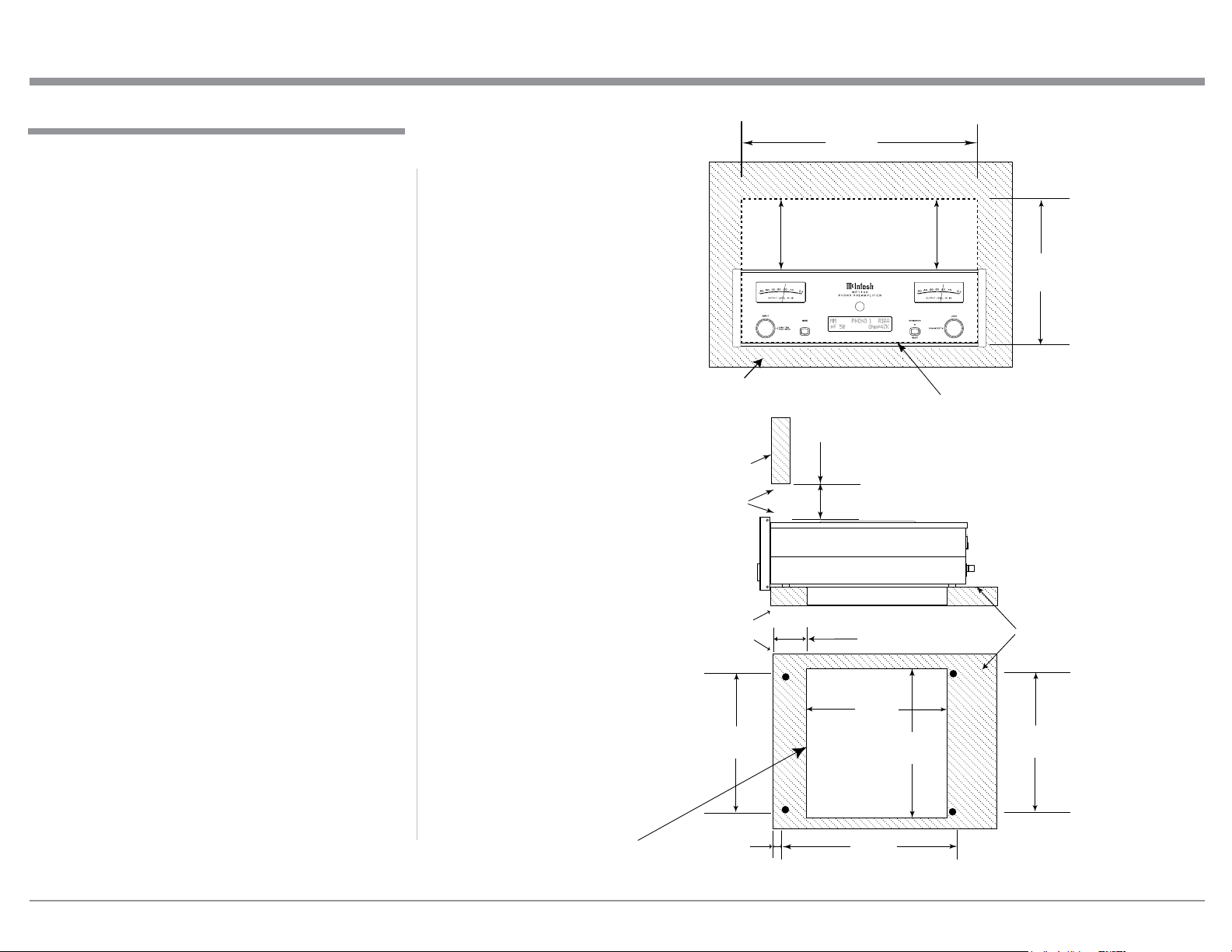
Installation
Installation
The MP1100 can be placed upright on a table or
shelf, standing on its four feet. It also can be custom
installed in a piece of furniture or cabinet of your
choice. The four feet may be removed from the bottom
of the MP1100 when it is custom installed as outlined below. The four feet together with the mounting
screws should be retained for possible future use if the
MP1100 is removed from the custom installation and
used free standing. The required panel cutout, ventilation cutout and unit dimensions are shown.
Always provide adequate ventilation for your
MP1100. Cool operation ensures the longest possible
operating life for any electronic instrument. Do not
install the MP1100 directly above a heat generating
component such as a high powered amplifier. If all
the components are installed in a single cabinet, a
quiet running ventilation fan can be a definite asset in
maintaining all the system components at the coolest
possible operating temperature.
A custom cabinet installation should provide the
following minimum spacing dimensions for cool
operation.
Allow at least 6 inches (15.2cm) above the top, 2
inches (5.1cm) below the bottom and 1 inch (2.5cm)
on each side of the Preamplifier, so that airf low is not
obstructed. Allow 18-1/2 inches (47.0m) depth behind
the front panel. Allow 1-7/16 inch (3.7cm) in front of
the mounting panel for knob clearance. Be sure to cut
out a ventilation hole in the mounting shelf according
to the dimensions in the drawing.
MP1100 Front Panel
Custom Cabinet Cutout
MP1100 Side View
in Custom Cabinet
MP1100 Bottom View
in Custom Cabinet
Cabinet Front Panel
Cabinet
Front
Panel
Opening
for Ventilation
Support
Shelf
15-1/16"
38.3cm
17-3/16"
43.66cm
Opening for Ventilation
Cutout Opening for Custom Mounting
6"
15.2cm
Cutout Opening
for Ventilation
7/8"
2-
7.3cm
8-1/8"
23.2cm
Cutout
Opening
for
Ventilation
13-1/8"
33.3cm
10-3/4"
27.3cm
Chassis
Spacers
15-1/16"
39.6cm
Note: Center the cutout Horizontally
on the unit. For purposes of
clarity, the above illustration
is not drawn to scale.
1-1/8"
2.9cm
12-5/16"
31.3cm
7
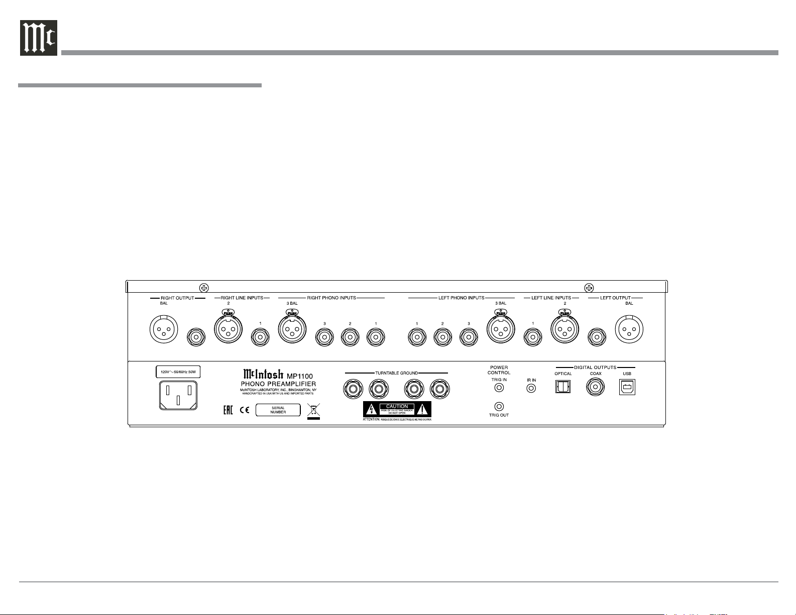
Rear Panel Connections
The identification of Rear Panel Connections for the
MP1100 Phono Preamplifier is located on a separate
folded sheet contained in the Owner’s Manual Packet.
Refer to separate sheet “Mc1B” for the Rear Panel
Connections.
Rear Panel Connections
MP1100 Phono Preamplifer Rear Panel
8

Connecting Components
The MP1100 has the ability to automatically switch
power On/Off from Components via the PWR CTRL
(Power Control) TRIGger connections. Follow the
connection instructions below, together with the
MP1100 Input/Output/Control Connection Diagram
located on a separate folded sheet “Mc1A” contained
in the Owner’s Manual Packet. The connections are
an example of a typical audio system. Your system
may vary from this, however the actual components
would be connected in a similar manner. For additional information refer to “Connector and Cable Information” on page 3.
Power Control (Trigger) Connections:
1. Connect a Control Cable from the MP1100 Power
Control TRIGger Out Jack to the Power Control In
on the Turntable 1.
2. Optionally, connect a Control Cable from the
Turntable 1 Power Control Out Jack to the Power
Control In on the Turntable 2.
3. Optionally, connect a Control Cable from the
Main Audio Preamplifier Power Control Out to
the MP1100 Power Control TRIGger IN.
Note: This optional Power Control Connection will
allow the MP1100 to automatically switch ON
and OFF when the Main Audio Preamplifier is
On or Off.
4. Connect any additional Components in a similar
manner, as outlined in steps 1 and 2.
Audio Connections:
5. Connect Audio Cables from the MP1100 PHONO
1 INPUT Jacks (Left and Right) to Turntable 1
(Left and Right) Output Jacks.
Note: If Turntable 1 has Balanced XLR Output Con-
nectors and has a Phono Cartridge installed
(with Balanced Output Connections), connect
XLR Audio Cables to the MP1100 PHONO 3
INPUT BALanced Connectors.
6. Optionally, connect Audio Cables from the
MP1100 PHONO 2 INPUT Jacks (Left and Right)
to Turntable 2 (Left and Right) Output Jacks.
Note: If Turntable 2 has Balanced XLR Output Con-
nectors and has a Phono Cartridge installed
(with Balanced Output Connections), connect
XLR Audio Cables to the MP1100 PHONO 3
INPUT BALanced Connectors.
7. Connect an additional Turntable in a similar manner, as outlined in steps 5 and 6.
8. Connect an Audio Cable from the MP1100 LINE
1 INPUT (Left and Right) Jacks to the Integrated
Amplifier REC Output Jacks.
Note: If the component has Balanced Output Con-
nections use the MP1100 LINE 2 BALanced
INPUT.
9. Connect any additional Components in a similar
manner, as outlined in step 8.
Optional USB Connection:
10. Connect a USB cable with (Type A to Type B)
connectors from the MP1100 USB DIGITAL
OUTPUT connector to an available USB connector on the computer.
Analog Output Connection:
11. Connect XLR audio cables from the MP1100
BALanced OUTPUT (Left and Right) to the Analog only Preamplifier Balanced Input 5 (Left and
Rig ht).
Note: If the Preamplifier has Unbalanced Inputs then
connect the MP1100 unbalanced Output Jacks
to the Preamplifier unbalanced Input Jacks.
Optional Digital Output Connection:
12. Connect a Digital Coaxial Cable from the MP1100
COAXial DIGITAL AUDIO OUTPUT Jack to
the Digital only Preamplifier Digital Audio Input
Coaxial 2 Jack.
Connecting Components
Note: If the Preamplifier has Optical Inputs then
connect the MP1100 Optical Output Connector
to the Preamplifier Optical Input Connector.
Ground Connections:
13. Connect the Ground Cable coming from the
Turntable(s) to the MP1100 TURNTABLE
GROUND Binding Post(s).
AC Power Cord Connections:
14. Connect the MP1100 to a live AC Outlet using the
supplied Power Supply Cord.
9
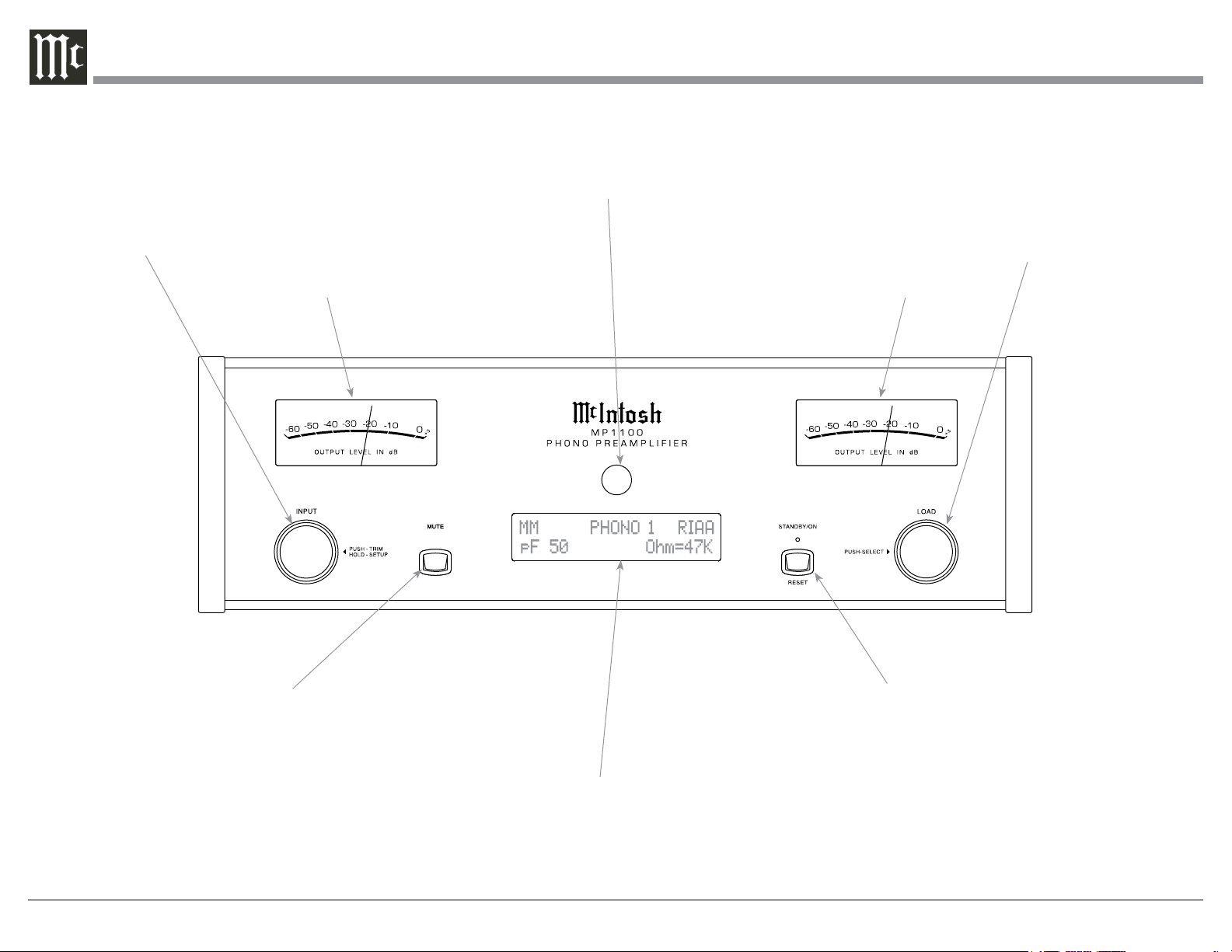
Front Panel Displays, Controls and Push-buttons
INPUT Control used to
select a source for listening
and recording. The control is
also used to enter the TRIM
or SETUP Modes and select
the various functions
Meter indicates the
Left Channel Output
of the Preamplifier
IR Sensor receives
commands from a
Remote Control
Meter indicates the
Right Channel Output
of the Preamplifier
LOAD Control used to
select the Resistance value
in Ohms and Capacitance
value in Picofarads that is
added to the Input Signal
Path for a flat Frequency
Response from the connected MM or MC Phono
Cartridge
10
MUTE Push-button mutes
the audio from the Loudspeakers and Headphones
STANDBY/ON Push-button
with indicator, switches the
MP1100 ON or OFF (Standby)
and resets the microprocessors
INFORMATION DISPLAY indicates the Sources, Resistive value in Ohms and Capacitance value in Picofarads,
other Audio Settings, Operational Functions and Setup
Mode Settings
 Loading...