

Page 1
MI-3
MAXIMUM PERFORMANCE
INDICATOR
SERVICE INFORMATION
STARTING WITH SERIAL NO, 10E01
MclNTOSH LABORATORY INC. 2 CHAMBERS STREET BINGHAMTON, NEW YORK
MI-3
Page 2
MI-3
SCHEMATIC NOTES
I. Unless otherwise specified: Resistance values are in ohms, 1/2 watt, and 10% tolerance;
capacitance values a re in microfarads (µF).
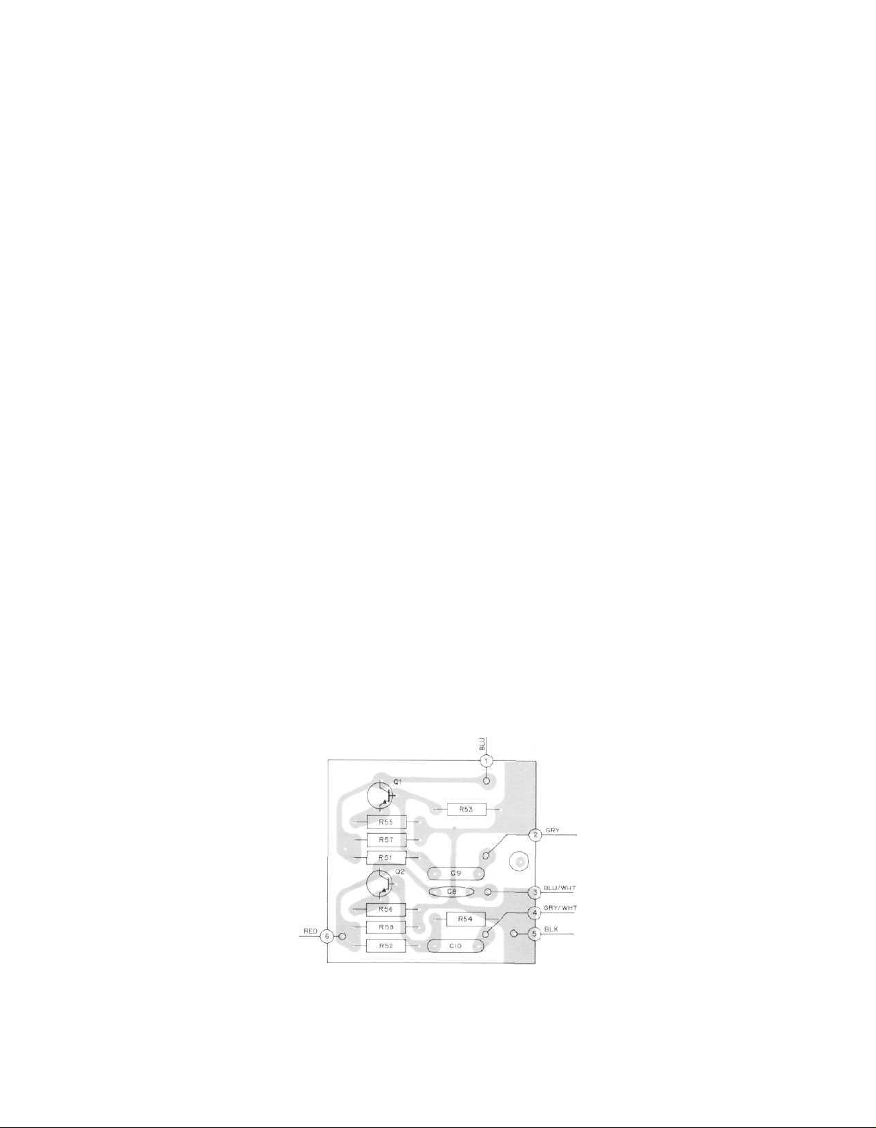
2 . Printed circuit board components are outlined on the schematics by dotted lines. The
circIed numbers around the dotted lines correspond to the numbers on the PC Board
layouts.
3. The terminal number ing of rotary switches is for reference only.
4. All voltages indicated on the schema tics are measured under the following conditions:
a. Use of an 11 megohm input impedance VTVM.
b. All voltages ±10% with respect to chassis ground.
c. No signal at input or antenna terminals.
d. AC
Input
at 117
e. Mode selector at test position.
5. In
6. In units with Serial No's from 10E26 to 15E00, R60 and R61 are used.
7. In units with Serial No's below 13E00, a 6W4 rectifier tube (Mclntosh Part No. 165-016)
8. In
units with
used in place of R59 •
is used in place of SR7 •
early units,
connected directly to pin No. 2 of S1 and the arm of R48B is connected directly to C7.
volts,
Serial
PC
Board
No's
50/60
below
043-984
Hz.
10E26,
two
neon
bulbs (Mclntosh Part
and R43 and R50 are not
used.
No.
058-002)
The arm of
R48A
are
is
AUDIO DRIVER
P.C. BOARD 043-984
Page 3

VERTICAL AMPLIFIER
043-984
8
AUDIO DRIVER
NOTE
P.C. BOARD
HORIZONTAL AMPLIFIER
Page 4

C.R.T. CIRCUIT
MI-3
Ml-3 154-434
Page 5

MI-3
REPLACEMENT PARTS
All parts not listed are common items obtainable from radio parts jobbers.
Replacement parts may be obtained when ordered
by PART NUMBER from:
Mclntosh Laboratory, Inc.
Customer Service Department
2 Chambers Street
Binghamton, New York 13903
(telephone 607-723-3512)
CAPACITORS
Symbol
Number
C3
C4
C5
C6
C7
C9, 10
C11
SR1,2
SR3,4
SR5,6
SR7
F1
Q1,2
T1
R1
R2
R3
R4
R5
R6
R29
R30
R32
MI-3
SCHEMATIC PART
Mylar .01 µF 400V
Elect. 20/20µF
Mylar -5µF 1000V
Elect. 8µF 475V
Mylar .22µF 200V
Mylar .22µF 250V
Mylar .1 µF 200V
Se. rectifier
Se. rectifier
Se. rectifier
Se. rectifier
Fuse 1 A slo-blo
Si . NPN transistor
NE2H Neon tube
Power transformer
Signal strength cal.
Deviation cal.
Left gain
Right gain
Vertical position
Horizontal position
Astigmatism
Intensity
Focus
Description
500/500V
DIODES
FUSES
TRANSISTORS
LAMPS
TRANSFORMERS
POTENTIOMETERS
NO.
038-462
Number
064-002
066-025
064-023
066-052
064-013
064-043
064-011
070-005
070-005
070-005
070-026
089-001
132-057
058-009
159-068
134-206
134-206
134-206
134-206
134-206
134-044
134-047
134-041
134-041
Part
R45
R48
R41
R42
S1
S2
V1 ,2
V3,4
V5
V6
V7,8
Vertical audio position
Audio gain
RESISTORS
Wirewound 15k 10% 10W
Wirewound 20k 10% 10W
SWITCHES
Selector switch
Power on-off
TUBES
6EA8
6EA8
3RP1 (CRT)
6EA8
OB2
FRONT PANEL & TRIM
Front panel
Front panel end cap: right
Front panel end cap: lef t
Power knob
Audio display knob
Intensity knob
Focus knob
Vertical position knob
Horizontal position knob
Scope test knob
MOUNTING SYSTEM
Shelf bracket: right
Shelf bracket: left
Mounting template #100
Hardware package
MISCELLANEOUS ITEMS
Fuseholder
AC power cord
Shipping carton
Owners manual
Audio cable
10C0819S7-M0462
134-206
134-171
139-040
139-018
146-100
146-040
165-044
165-044
165-028
165-044
165-027
043-697
018-132
018-133
043-253
043-253
043-478
043-478
043-478
043-478
043-806
043-427
043-428
038-179
043-458
178-001
170-021
043-943
038-142
170-015
 Loading...