

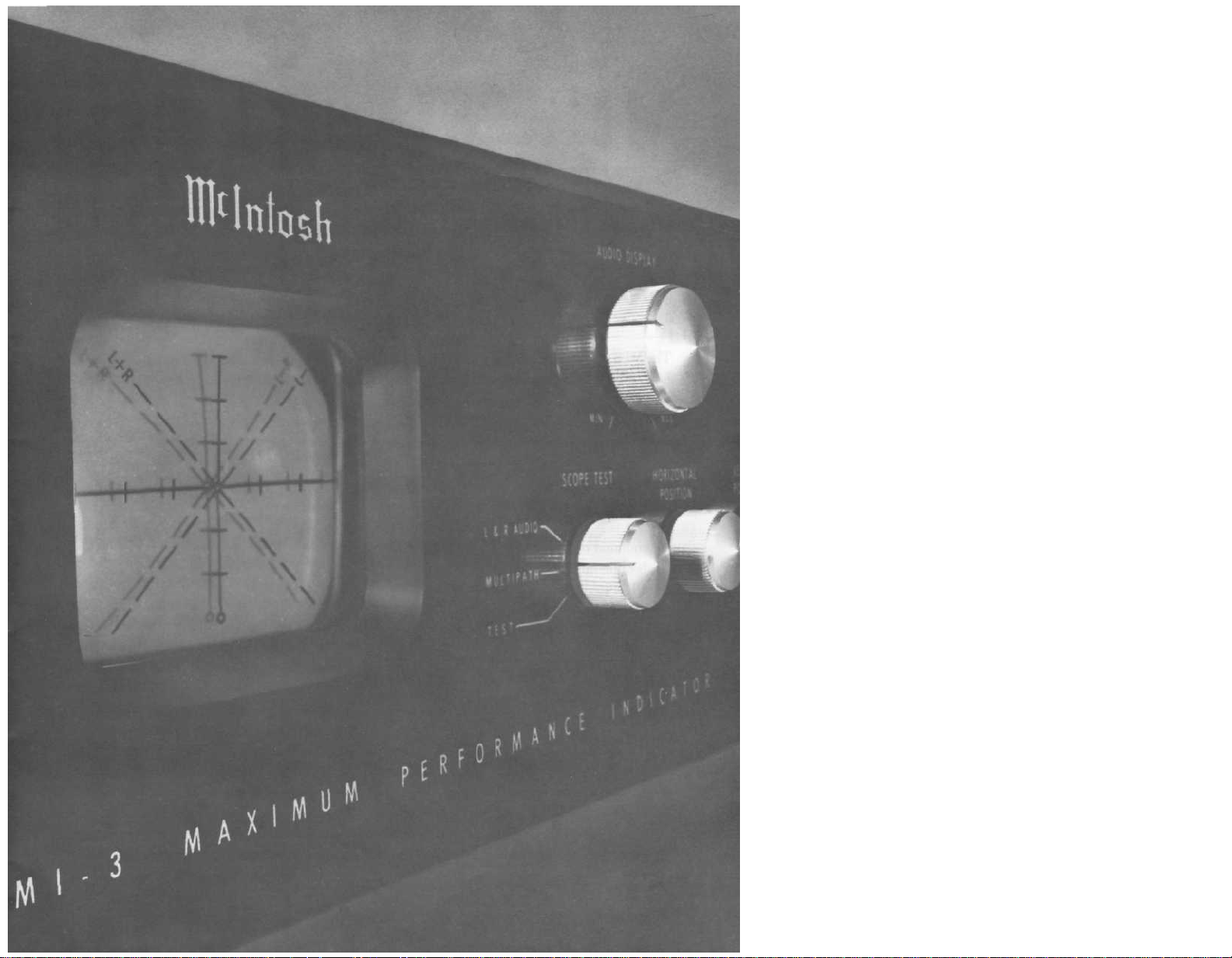
McIntosh MI-3 Owners manual

MAXIMUM
PERFORMANCE
MI3
INDICATOR


GENERAL
DESCRIPTION
THANK YOU for
purchasing this Ml 3. To
insure your enjoyment
please read this manual
carefully and follow
instructions.
CONTENTS
GENERAL DESCRIPTION 1
TECHNICAL DESCRIPTION 2
SPECIFICATIONS 3
FRONT PANEL INFORMATION 4
BACK PANEL INFORMATION 5
CABINET INSTALLATIONS 6
CONNECTIONS 7, 8
SET UP PROCEDURES 9
SYSTEM HOOK UP 10
TYPICAL PATTERNS 11
GUARANTEE 12
The Mclntosh Ml 3 is five laboratory instruments combined into one
compact instrument. It is a professional oscilloscope, relative signal
strength indicator, calibrated FM deviation meter, calibrated balance
meter, and phase indicator. These instruments are used by FM stations
to determine the best possible performance for your listening enjoyment.
The Mclntosh Ml 3 Maximum Performance Indicator makes it easy for
you to attain professional broadcasting quality FM listening.
The Mclntosh Ml 3 shows you what you need to do to improve your
system's overall performance. It is designed to be used with an FM
tuner and stereo preamplifier.
When the Ml 3 is used with an FM tuner it will detect and display
multipath reception. Multipath reception is the result of a reflected
signal arriving at the tuner antenna slightly later than the direct signal.
By rotating or repositioning your FM antenna it is possible to reduce
the multipath reception. The Ml 3 Maximum Performance Indicator
makes it easy to know when the FM antenna is oriented for the best
reception of any station.
To show multipath reception the Ml 3 displays instantaneous signal
strength versus frequency deviation. Signal strength is shown as vertical
deflection of the indicator display beam. Frequency deviation is shown
as horizontal deflection. Multipath reception appears as a peak or
valley in the Ml 3 picture tube display.
Multipath reception degrades FM tuner performance in several ways:
1. Usually there is an increase in background noise level.
2. Distortion is often heard in the program signal.
3. Stereo separation may be reduced.
4. The stereo effect may be completely lost.
5. Stereo indicators may fail to function, or function erratically.
To overcome multipath reception it is usually necessary to turn the
antenna to receive the FM signal by one predominant path. Rotating a
directional antenna is effective at correcting multipath reception. In a
metropolitan area where a simple antenna
repositioning
The Ml 3 is a very effective tuning indicator:
1. Signal strength is shown by the vertical position of the display
trace. The higher the position of the trace the greater the signal
strength.
the
antenna
will
achieve
the
such
same
as a
result.
dipole
is
used
MAXIMUM
PERFORMANCE
INDICATOR
MI3
1

2. Correct tuning occurs when the display trace is centered horizontally on the screen. Since the display trace effectively follows
the tuner I.F. response curve, centering the trace tunes the detector to the center of the I.F. curve.
The Ml 3 Maximum Performance Indicator is a versatile instrument.
When used with either a stereo preamplifier, or power amplifier the
Ml 3 when switched to the L+R AUDIO position will show you the
character of the audio signals present. The Ml 3 will:
1. Display a trace along the L+R line when a monaural program
is playing.
2. Will display along the L —R line when a monaural program
source has one channel out of phase.
3. Display a vertical trace if only the left channel is being delivered.
4. Display a horizontal trace when only the right channel is being
delivered.
5. Helps you set the precise balance of your system. With the balance control you can change the angle of the L+R or L—R display.
6. A stereo program will be a complex and varying circular or
elliptical display of irregular outline that depends on channel
separation or on the phase amplitude relation of the left and
right channel.
TECHNICAL
DESCRIPTION
The Ml 3 Maximum Performance Indicator is essentially an oscilloscope
using a three inch cathode-ray tube. Adequate brightness is assured
with a 1350 volt accelerating voltage. A sharper well defined trace is
provided by using separate focus and astigmatism controls.
Two identical direct coupled push-pull amplifiers are used in the hori-
zontal and vertical deflection circuits. Phase shift in each amplifier Is
held to within a few degrees from D.C. throughout the operating
frequency range. Phase differences between vertical and horizontal
amplifiers are held to within a few degrees.
The high voltage power supply uses a selenium rectifier. The low voltage supplies use selenium rectifiers, two gas filled rectangular tubes
and an electronic voltage regulator. The operating voltages from
these supplies are carefully regulated over a wide range of power
line variations. This design feature assures a steady indicator trace
despite changing line voltage.
For multipath display the horizontal deflection voltage is obtained
from the tuner discriminator output ahead of the de-emphasis network.
This voltage is proportional to the frequency deviation of the FM
transmission. The maximum width of the indicator screen is designed to
correspond to approximately plus and minus 75 kilocycle deviation of
the FM transmitter.
The horizontal multipath input is connected through the deviation input
jack and the deviation (horizontal) calibration control.
For multipath display the vertical deflection voltage is obtained from
the tuner Automatic Gain Control circuit at the input to the first limiter.
This voltage is proportional to the FM stations instantaneous signal
strength. However, the average proportionally is expotential. Because
of the expotential characteristic, a weak station will produce adequate
vertical deflection. A powerful local station should position the center
of the indicator trace about half to three quarters of an inch below the
top of the vertical scale. The vertical Multipath Input is connected
through the Signal Strength Input and the Signal Strength (vertical)
Calibration Input Control.
For L+R audio display the horizontal deflection voltage is obtained
from the right channel output of a tuner, a preamplifier or even a
power amplifier. The deflection voltage is connected through the
Right Audio Input and the Right Gain Control. For L + R audio display
the vertical deflection voltage is obtained from the left channel output
of a tuner, a preamplifier, or a power amplifier. The deflection voltage
is connected through the Left Audio Input and the Left Gain Control.
With a normal loudness monaural signal both audio input controls are
adjusted for equal deflection of the display trace. (At this point the
trace will be on the L + R line if the two signals are in phase or the
L - R line if they are 1 80° out of phase.)
MI3 SPECIFICATIONS
SENSITIVITY
Signal Strength (vertical) Input — 700 MV
Left Audio (vertical) Input 20 MV
Deviation (horizontal) Input ±350 MV
Right Audio (horizontal) Input 20 MV
DIMENSIONS
Front panel: 16 inches wide by 5-7/16 inches
high;
chassis
inches wide by 5 inches high by 13 inches
deep, including connectors; clearance in
front of mounting panel including knobs,
1 ½ inches.
TUBE AND SEMICONDUCTOR
COMPLEMENT
1—3RP1, 3 inch cathode ray tube.
4—6EA8, horizontal and vertical deflection
amplifiers.
1—6EA8, electronic voltage regulator.
2—OB2, voltage regulators.
1—Selenium rectifier, high voltage rectifier.
6—Selenium rectifiers, low-voltage supply.
4—silicon planar transistors.
(including PANLOC
shelf)
15
WEIGHT
Chassis only, 23 pounds.
In shipping carton, 30 pounds.
FINISH
Anodized gold and black glass front panel
POWER CONSUMPTION
50 watts, 105 to125 volts.
50 to 60 cycles.
FUSE
1 Ampere Slo-Blo
3
 Loading...