

1A
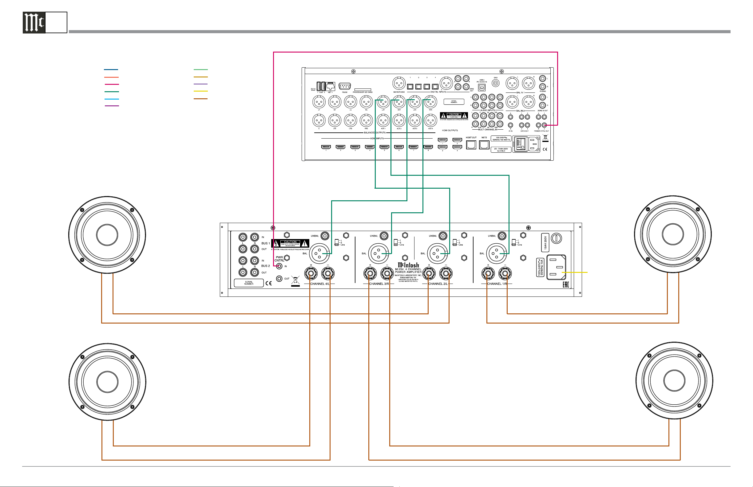
Note: Refer to the MI254 Owner’s Manual pages 8 &9 for additional connection information.
MI254 Multi Channel System Connection Diagram
Connection Legend:
Data Cable*- Digital Signal Cable Sensor/Keypad Cable - Network/RS232 Cable Power Control Cable* - Ground Wire Audio Signal Cable - AC Power Cords -
Video Signal Cable - Loudspeaker Cable RF Signal Cable -
* 2 conductor shielded with 1/8 inch stereo mini phone plug on each end.
Front Left Ceiling Height Loudspeaker
A/V Control Center
Front Right Ceiling Height Loudspeaker
-
Rear Left Ceiling Height Loudspeaker
-
+
+
Connect to
AC Out le t
-
Rear Right Ceiling Height Loudspeaker
+
-
+
McIntosh Laboratory, Inc. 2 Chambers Street Binghamton, New York 13903-2699 Phone: 607-723-3512 www.mcintoshlabs.com Part No. 04190500
1B
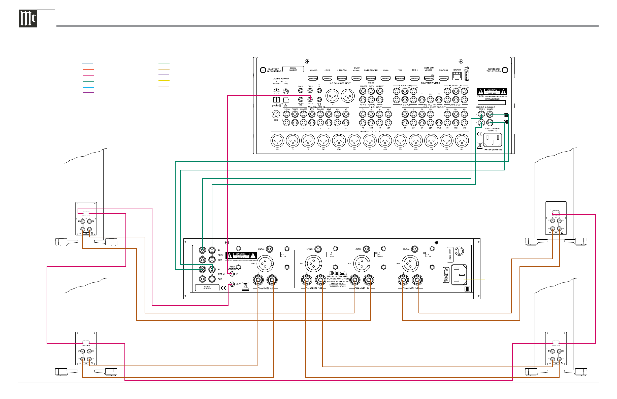
Note: Refer to the MI254 Owner’s Manual pages 10 & 11 for additional connection information.
MI254 System Connection Diagram, Different Sources for Zones B and C
Connection Legend:
Data Cable*- Digital Signal Cable Sensor/Keypad Cable - Network/RS232 Cable Power Control Cable* - Ground Wire Audio Signal Cable - AC Power Cords -
Video Signal Cable - Loudspeaker Cable RF Signal Cable -
* 2 conductor shielded with 1/8 inch stereo mini phone plug on each end.
Zone B Left Loudspeaker
A/V Control Center
Zone B Right Loudspeaker
+
-
Zone C Left Loudspeaker
+
-
Connect to
AC Out le t
-
+
Zone C Right Loudspeaker
-
+
McIntosh Laboratory, Inc. 2 Chambers Street Binghamton, New York 13903-2699 Phone: 607-723-3512 www.mcintoshlabs.com
 Loading...