

McIntosh MI-2 Owners manual
MULTIPATH/
TABLE OF CONTENTS
TUNING INDICATOR
GENERAL DESCRIPTION 1
TECHNICAL DESCRIPTION 3
Specifications 3
FRONT PANEL INFORMATION 4
BACK PANEL INFORMATION 5
INSTALLATION 6
CONNECTING 8
Connecting to Mclntosh MR67 Tuner 8
Connecting to Mclntosh MX110 Tuner-Pre-
amplifier with Z or X Serial Numbers 8
Connecting to Mclntosh MX110 Tuner-Pre-
amplifier with M Serial Numbers 10
Connecting to Mclntosh MR65B Tuner 10
Connecting to Mclntosh MR65 and MR65A
Tuner 10
Connecting to Mclntosh MR66 Tuner 10
Connecting to Mclntosh MR55A Tuner 10
Connecting to Mclntosh MR55 Tuner 10
Connecting to All Other Tuners 11
OPERATING INSTRUCTIONS 12
GUARANTEE 16
3-YEAR FACTORY SERVICE CONTRACT 16
MI-2
MI-2
MI-2 MULTIPATH/TUNING INDICATOR
GENERAL DESCRIPTION
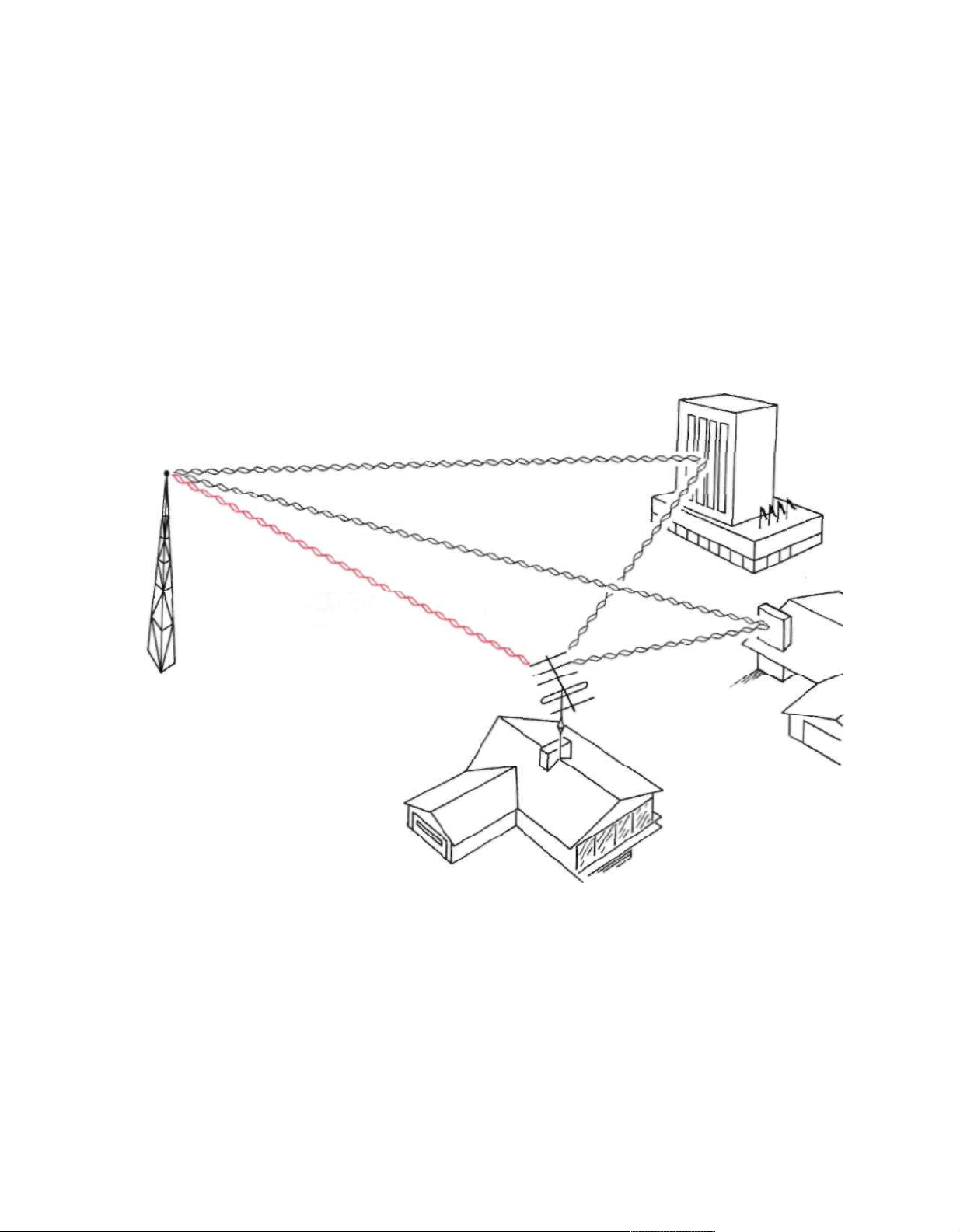
The Mclntosh MI-2 Multipath/Tuning Indicator is designed to be used with an FM tuner
to detect and display multipath reception.
Multipath reception is the result of a reflected
signal arriving at the tuner antenna slightly
later than the direct signal. By rotating or
repositioning your FM antenna it is possible
to reduce the multipath reception. The MI-2
Multipath/Tuning Indicator makes it easy to
know when the FM antenna is oriented for
the best reception of any station.
DIRECT
SIGNAL
Multipath reception degrades FM tuner
performance in several ways:
1) Usually there is an increase in back-
2) Distortion is often heard in the pro-
3) Stereo separation may be reduced.
4) The stereo effect may be completely
5) Stereo indicators may fail to function,
REFLECTED
ground noise level.
gram signal.
lost.
or function erratically.
SIGNALS
Figure 1. FM Tuner Antenna Receiving
Direct and Reflected Signals
To show multipath reception the MI-2 dis-
plays instantaneous signal strength versus
frequency deviation. Signal strength is shown
as vertical deflection of the indicator display
beam. Frequency deviation is shown as horizontal deflection. Multipath reception appears as a peak or a valley in the MI-2 display. See Figure 2.
To overcome multipath reception it is
usually necessary to orient the tuner antenna
to receive the FM signal by only one predominant path. Rotating a directional antenna is
very effective at correcting multipath reception. In a metropolitan area where a simple
antenna such as a dipole is used repositioning the antenna will achieve the same result.
1
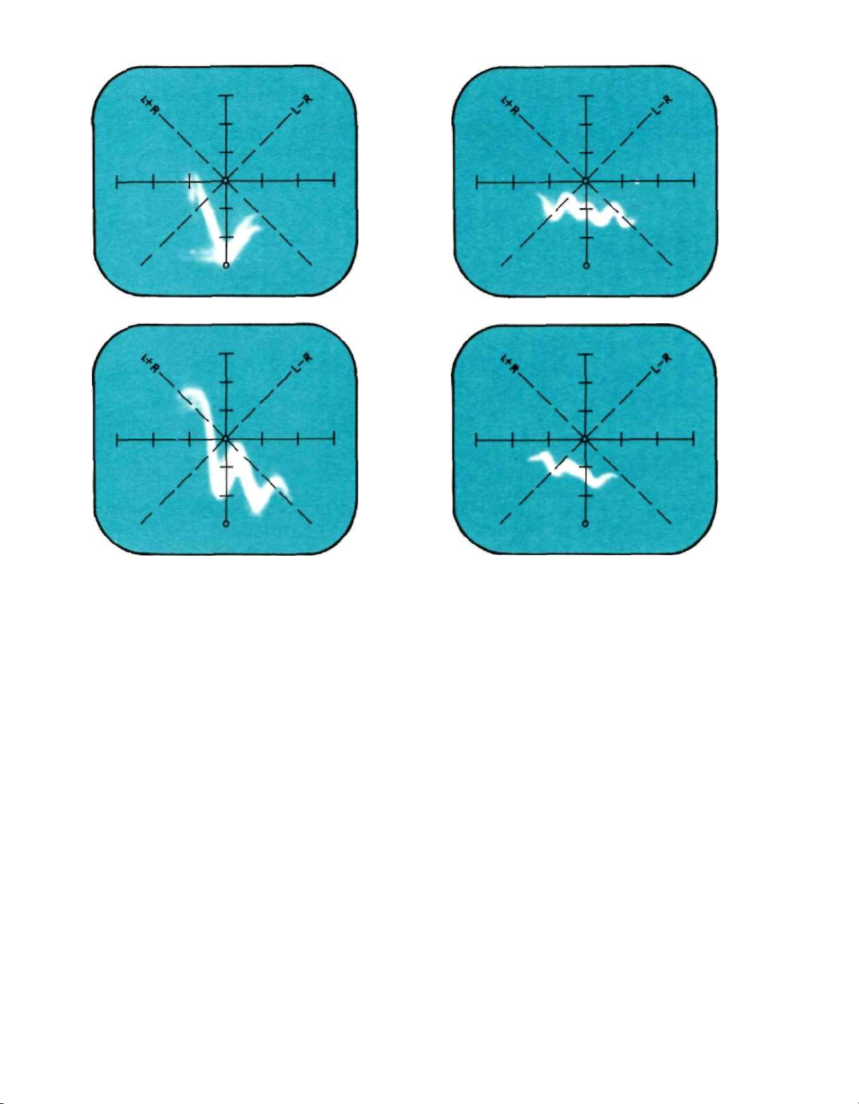
(2a)
(2 b)
(2c)
Figure 2. Various Forms of Multipath Reception
As They Appear on the MI-2 Display Screen.
Such a change may be as little as a fraction
of a foot or as much as several feet.
The MI-2 is also a very effective tuning
indicator:
1) Signal strength is shown by the vertical
position of the display trace. The higher
the position of the trace the greater is
the signal strength.
2) Correct tuning occurs when the display
trace is centered horizontally on the
screen. Since the display trace effectively follows the tuner I.F. response
curve, centering the trace tunes the
detector to the center of the I.F. curve.
The Mclntosh MI-2 Multipath/Tuning Indi-
cator is a versatile instrument. Its usefulness
has been extended to show other signal voltages. By turning the SCOPE TEST switch to
the L & R AUDIO position the MI-2 shows the
stereo or monaural character of the audio
signals).
(2d)
1) A trace display along the L+R line will
occur with a monaural program source.
2) A trace display along the L-R line will
occur with a monaural program source
if the phase of one channel is reversed.
3) A vertical trace indicates that the program is being delivered to the left
channel only.
4) A horizontal trace indicates that the
program is being delivered to the right
channel only.
5) Operating the balance control on your
tuner-preamplifier or system preamplifier can change the slope angle of the
L+R or L-R display.
6) A stereo program will be a complex and
varying circular or elliptical display of
irregular outline that depends on chan-
nel separation or on the phase amplitude relation of the Left and Right
channel.
2

TECHNICAL DESCRIPTION
The MI-2 Multipath/Tuning Indicator is
essentially an oscilloscope using a three inch
cathode-ray tube. Adequate brightness is
assured by using a 1350 volt accelerating
voltage. To provide a sharp and well defined
trace, the MI-2 uses separate focus and astigmatism controls.
Two identical direct coupled push-pull
amplifiers are used in the horizontal and
vertical deflection circuits. Phase shift in
each amplifier is held to within a few degrees
from D.C. throughout the operating fre-
quency range. Phase differences between
vertical and horizontal amplifiers are also
held to within a few degrees.
The high-voltage power supply uses a 6W4
tube rectifier. Two low-voltage supplies use
selenium rectifiers, two gas filled regulator
tubes and an electronic voltage regulator.
The operating voltages from these supplies
are carefully regulated over a wide range of
power line variations. This design feature
assures a steady indicator trace despite
changing line voltage.
For Multipath display the horizontal deflection voltage is obtained from the tuner
discriminator output ahead of the de-emphasis network. This voltage is proportional to
the frequency deviation of the FM transmis-
sion. The maximum width of the indicator
screen is designed to correspond to approxi-
mately plus and minus 75 kilocycle deviation
of the FM transmitter.
The horizontal multipath input is con-
nected through the Deviation Input jack and
the Deviation (horizontal) calibration control.
For multipath display the vertical deflection voltage is obtained from the tuner Automatic Gain Control circuit at the input to the
first limiter. This voltage is proportional to FM
station's instantaneous signal strength. However the average proportionality is exponential. Because of the exponential characteristic, a weak station will produce adequate
vertical deflection. A powerful local station
should position the center of the indicator
trace about half to three quarters of an inch
below the top of the vertical scale.
The vertical Multipath Input is connected
through the Signal Strength Input and the
Signal Strength (vertical) Calibration Input
Control.
For L & R Audio display the horizontal deflection voltage is obtained from the right
channel output of a tuner, a preamplifier or
even a power amplifier. This deflection voltage is connected through the Right Audio
Input and the Right Gain Control.
For L & R Audio display the vertical deflection voltage is obtained from the left channel
output of a tuner, a preamplifier or a power
amplifier. This deflection voltage is con-
nected through the Left Audio Input and the
Left Gain Control.
With a normal loudness monaural signal
both audio input controls are adjusted for
equal deflection of the display trace. At this
point the trace will lie on the L+R line if the
two signals are in phase or the L-R line if
they are 180° out of phase.
MI-2 SPECIFICATIONS
Sensitivity
Signal Strength (Vertical) Input
0.37 Volts per Cm.
Left Gain (Vertical) Input 0.37 Volts per Cm.
Deviation (Horizontal) Input
0.27 Volts per Cm.
Right Gain (Horizontal) Input
0.27 Volts per Cm.
Dimensions
Front panel 155/8 inches x 51/8 inches; overall
depth of chassis behind front panel, 11½
inches; clearance in front of mounting
panel including knobs, 1 inch.
Tube and Semiconductor Complement
1—3RP1, 3 inch Cathode Ray tube.
4—6U8, Horizontal and Vertical Deflection
amplifiers
1—6U8, Electronic Voltage Regulator.
1-6W4, High Voltage Rectifier.
2-OB2, Voltage Regulators.
6—Selenium Rectifiers, low-voltage supply.
Weight
Chassis only,22pounds.
In shipping carton, 29 pounds.
Finish
Anodized gold and black glass front panel.
3
Power Consumption
50 watts, 105 to 125 volts.
50 to 60 cycles.
Fuse
1 Ampere SLO BLO
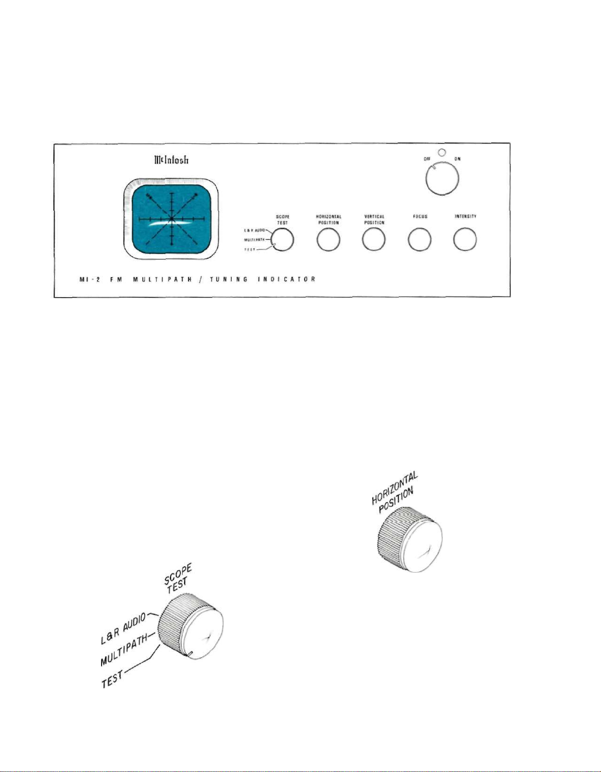
FRONT PANEL INFORMATION
Figure 3. MI-2 FM MULTIPATH/TUNING INDICATOR
Front Panel.
INDICATOR SCREEN
The screen is the face of a cathode ray
tube. Calibration marks are provided to allow
correct positioning of the indicator trace.
A correctly tuned station free of multi-
path distortion will appear as a smooth curve
centered on the indicator screen vertical
scale. The vertical line is marked to show the
relative strength of the FM signal. A strong
local signal should position the display
about ½ to ¾ inch from the top of the vertical
scale. The horizontal line is marked to show
deviation.
The two 45° sloped lines show L + R and
L - R information.
SCOPE TEST
This control switches the indicator circuits
to show Multipath, Left and Right audio
signals or Test. The TEST position switches
the indicator trace to a single dot for adjustment of trace position, focus and intensity.
Different trace reference positions are necessary for multipath and L & R Audio.
HORIZONTAL POSITION
Figure 5. HORIZONTAL POSITION Control.
This control moves the indicator trace to
the left or right. With the Scope Test switch
in TEST position, the trace dot can easily be
centered on the indicator screen.
VERTICAL POSITION
This control moves the indicator trace up
Figure 4. SCOPE TEST Control.
4
or down. With the Scope Test switch in TEST
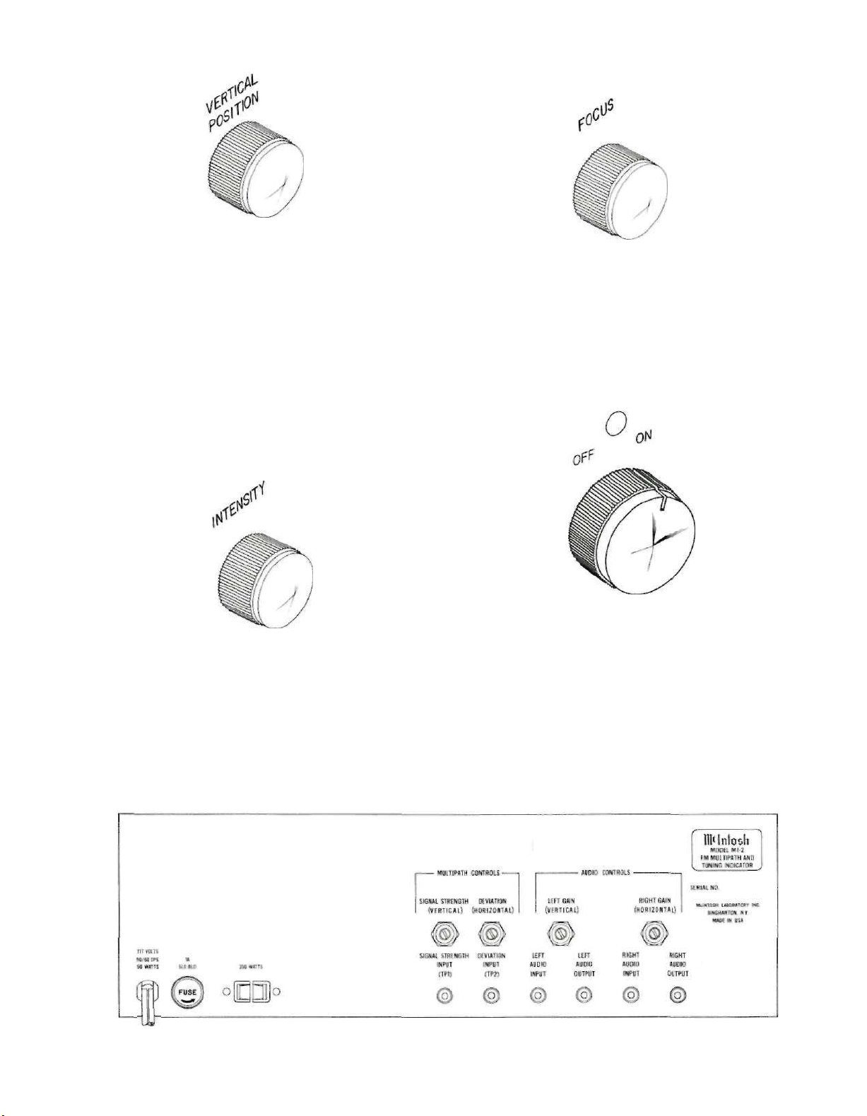
Figure 6. VERTICAL POSITION Control.
position the indicator trace can be easily
moved to the correct vertical position. For
Multipath display the trace is positioned at
the bottom reference point (point A). For
audio indications the trace is positioned at
the center reference point (point B). This
shift in position occurs automatically as the
Scope Test Control is turned. An internal
adjustment labeled "L & R position" is
factory preset but can be read justed if needed.
INTENSITY
FOCUS
Figure 8. FOCUS Control
This control adjusts the sharpness and
clarity of the indicator trace. Focus is easiest
with the Scope Test switch in TEST position.
Figure 7. INTENSITY Control.
This control adjusts the brightness of the
indicator trace. After the Intensity control
has been turned, the Focus control may have
to be readjusted for the best possible indicator trace.
BACK PANEL INFORMATION
Figure 9. ON-OFF SWITCH PILOT LIGHT
Figure 10. MI-2 FM MULTIPATH/TUNING INDICATOR
Back Panel.
5
 Loading...