

Mcintosh MC 2500, MC 2255, MC 2250, MC 2155, MC 2120 catalog
...
The World Wide Leader
In State Of The Art
High Fidelity Technology
Engineered and Manufactured
in the United States of America
Mclntosh Laboratory Inc.
2 Chambers Street
Binghamton, New York, 13903-9990
Phone 607-723-3512


TABLE OF CONTENTS
Power Amplifiers:
MC 2500, MC 2255, MC 2250, MC 2155, MC 2120,
MC 502
PreAmplifiers:
C 33, C 29, C 27, C 504
Tuners:
MR 80, MR 78, MR 75 25-37
Tuner-Preamplifier:
MX 117 38-45
Receiver:
MAC4100 AM/FM Receiver 46-50
Preamplifier- Amplifier:
MA6200 51
Loudspeakers: 52-65
The Mclntosh Story 66-67
Equalizers:
MQ107, MQ 104 68
2-16
14-24
YOU SHOULD OWN
McIntosh
BECAUSE
• Mclntosh instruments are designed and manufactured for long life.
• Mclntosh instruments have always
been designed for long life with low
maintenance costs and high quality performance. Mclntosh instruments have been and are the
LABORATORY STANDARD
for the world.
• Until 1949 the performance requirements for a Mclntosh had
long been an engineering dream.
They became a reality with the introduction of the first Mclntosh
amplifier. Through all these years
Mclntosh has produced instru-
ments that have exceptionally long
life. Clinics held ail over North
America have shown that most of
the Mclntosh instruments ever
manufactured still meet or exceed
their original exacting specifications.
• Used McIntosh instruments have
the highest resale value. Retailers
report that customers are constantly searching for used Mclntosh in-
struments. A Mclntosh does not re-
main on the "Used" display long.
You'll get more when you trade-in
your Mclntosh assuring you of
maximum return on your invest-
ment,
• Mclntosh dedication, not only to
improvements, but also to fun-
damentals, has justified many
patents on basic circuit structures
as well as refinements.
• Doesn't it make good sense to deal
with a company that wants to do as
much for you as it possibly can?
FM Guide. . . 69-76
1
THE NEW
MCINTOSH AMPLIFIERS
Mclntosh leadership in research and bipolar
epitaxial transistor technology has produced
startling new advances in safe, cool,
superior performance and protection.
Mclntosh engineering continues to advance
power amplifier technology and protected performance. Experience and knowledge are the foundation on which the engineering superstructure is
built that supports the Mclntosh recognized reputation as Laboratory Standard for the world. A new
level of technology and a higher level of amplifier
performance is realized in the all new Mclntosh
Amplifiers.
LEADERSHIP
• Mclntosh life testing selects only components
that give the most trouble free performance. Added care in engineering, design and manufacturing
produces long product life at the peak of perfor-
mance.
LEADERSHIP
• Mclntosh POWER GUARD assures maximum amplifier power without clipping distortion.
LEADERSHIP
• Mclntosh engineers developed a unique output
circuit configuration that is temperature stable
and that delivers clean output power at any level
without a trace of crossover distortion.
LEADERSHIP
• Mclntosh Automatic System . Test provides
positive protection and extends the long trouble
free life of an amplifier. Each time an amplifier is
turned on, seven tests are completed that
measure and verify accurate performance.
LEADERSHIP
• Mclntosh Output Autotransformers deliver full
power output and multiple feedback loops assure
lowest distortion at all power levels and all
speaker impedances.
LEADERSHIP
• Mclntosh designed mute circuits give positive
protection from transients due to turn on, turn off
power supply voltage changes.
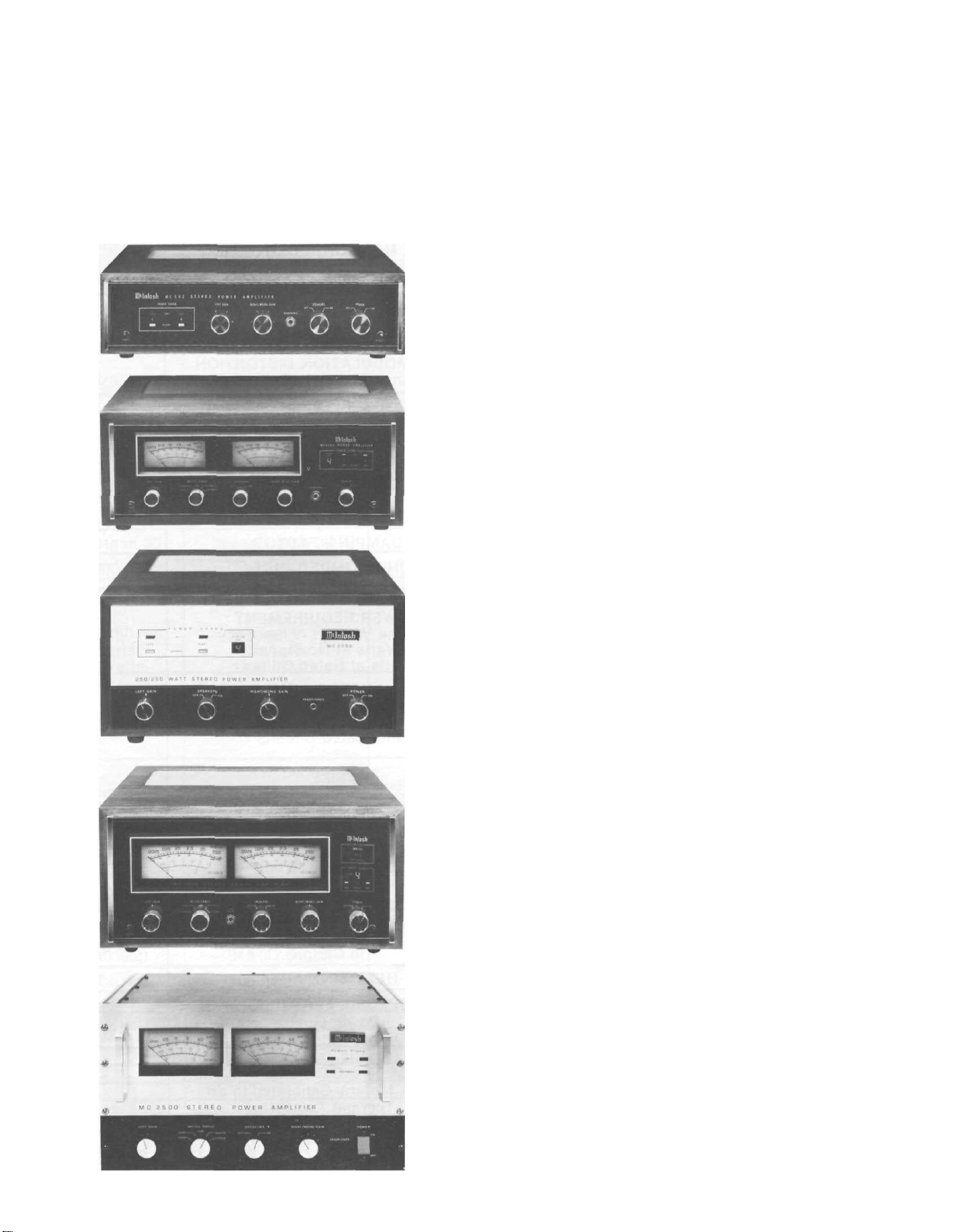
MC 2255 Shown in optional walnut veneer cabinet
2
YOU ARE PROTECTED FROM
LISTENING TO AMPLIFIER
PRODUCED DISTORTION
WITH MCINTOSH
POWER GUARD
Plus:
• Mclntosh Output Autotransformer delivers full
power output. Multiple feedback loops assure
lowest distortion at all power levels and all
speaker impedances
• Mclntosh engineers developed a unique output
stage circuit arrangement that is completely
temperature accurate, that delivers clean output
power at any level without crossover distortion
• Mclntosh life testing of components permits component selection for trouble-free performance; ad-
ded care in production engineering and manufacturing results in long product life
• Mclntosh designed "turn-on/mute" circuits pro-
vide positive protection from "turn-on transients"
and other potentially damaging noises
• Mclntosh POWER GUARD assures maximum
amplifier power without clipping distortion
Higher power demands on amplifiers have
presented music listeners with a form of unpleasntness in listening, amplifier overload (hard clipping)
that looks and acts like square waves. Clipping is
caused when the amplifier is asked to produce more
power output with low distortion than it can deliver.
Clipping of a complex wave form is largely composed of odd order harmonics and intermodulation products. High order odd harmonics and intermodula-
tion products are dissonant and are not musically
related to the signal being amplified. They are heard
as great and disappointing discordance and distor-
tion.
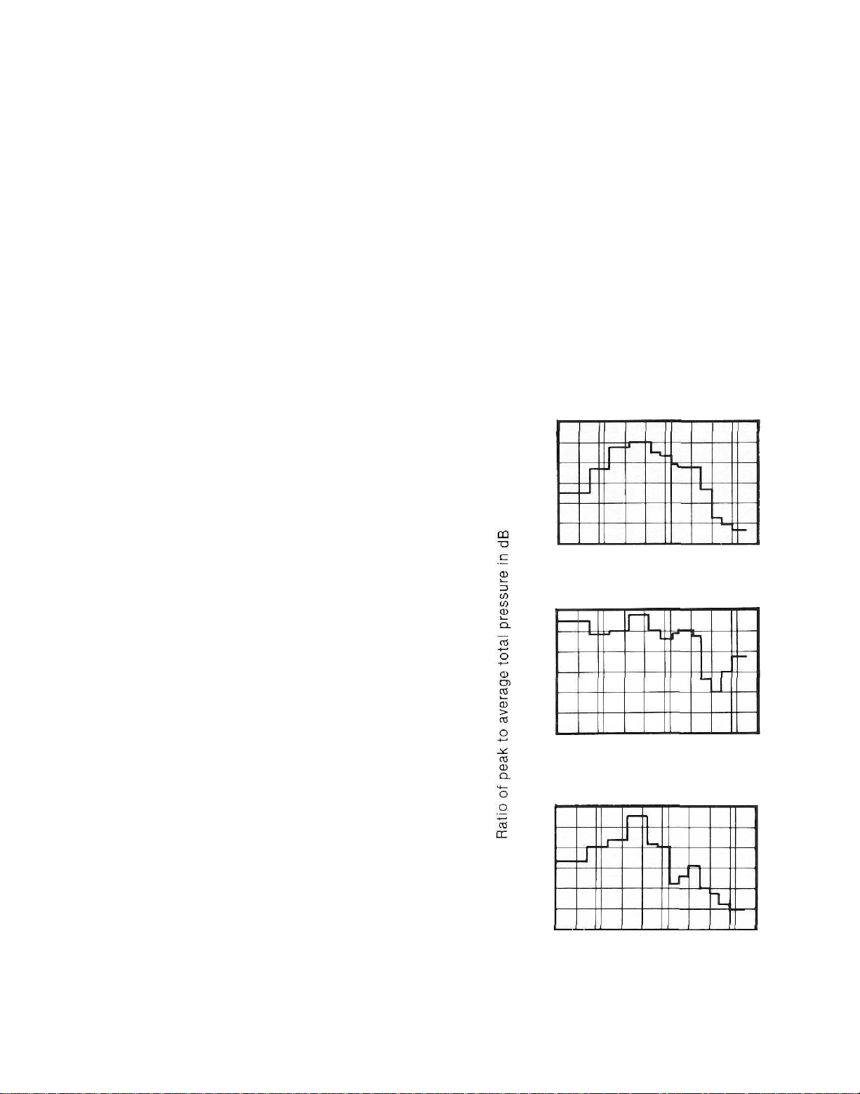
In most acoustical events we may listen to surprisingly low average power output but the peak
power requirements can be very high. Consider
these graphs of the power demanded of an amplifier
reproducing the piano, the pipe organ, and the bass
saxophone. The charts show that the peak power demand is almost 1000 times (30 dB) the average power
demand. Since it is necessary that these short inter-
val power spikes be reproduced with low distortion,
it means the average power output of the power
amplifier must be limited to 1/1000th of its capability
or the listener must accept the discordant distortion
of clipping.
Amplifiers when driven to clipping are capable of
delivering up to twice the heat load to the
loudspeaker. In addition, they can have more than
40% harmonic distortion. The extra heat energy content of the clipped signal will damage most
speakers. Mclntosh leadership in engineering has
developed a new circuit that...(1) dynamically
prevents power amplifiers from being overdriven in-
30
0
-30
20 100 1K 10K
30
0
-30
20 100 1K 10K
30
0
-30
20 100 1K 10K
to hard clipping. ..(2) which reduces the heat
developed in the loudspeakers. ..(3) assures that the
amplifier will produce its maximum output without
increased distortion. That circuit we call "POWER
GUARD."
PIANO
HERTZ
PIPE ORGAN
HERTZ
BASS SAXOPHONE
HERTZ
3
THE MCINTOSH POWER GUARD
The Power Guard waveform comparison circuit
detects minute amounts of waveform difference between the output signal and the input signal. A
sampling of the program material at the output of
the amplifier is constantly compared with the program material at the amplifier input. Should the differences reach 1%, Power Guard goes to work.
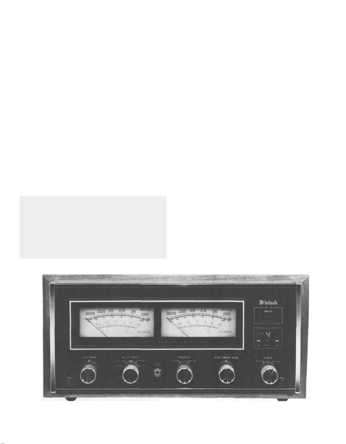
THE MCINTOSH POWER METERS
Mclntosh developed output monitoring meters
add to your operating flexibility. Ordinary meters are
incapable of indicating the short interval informa-
tion in a sound wave. The mass of the meter move-
ment is too great to respond to the instantaneous
changes in music program material. That short interval information can have a duration as brief as one-
half of one thousandth of a second. Even should the
meter be capable of the high velocity movement the
human eye could not perceive the information.
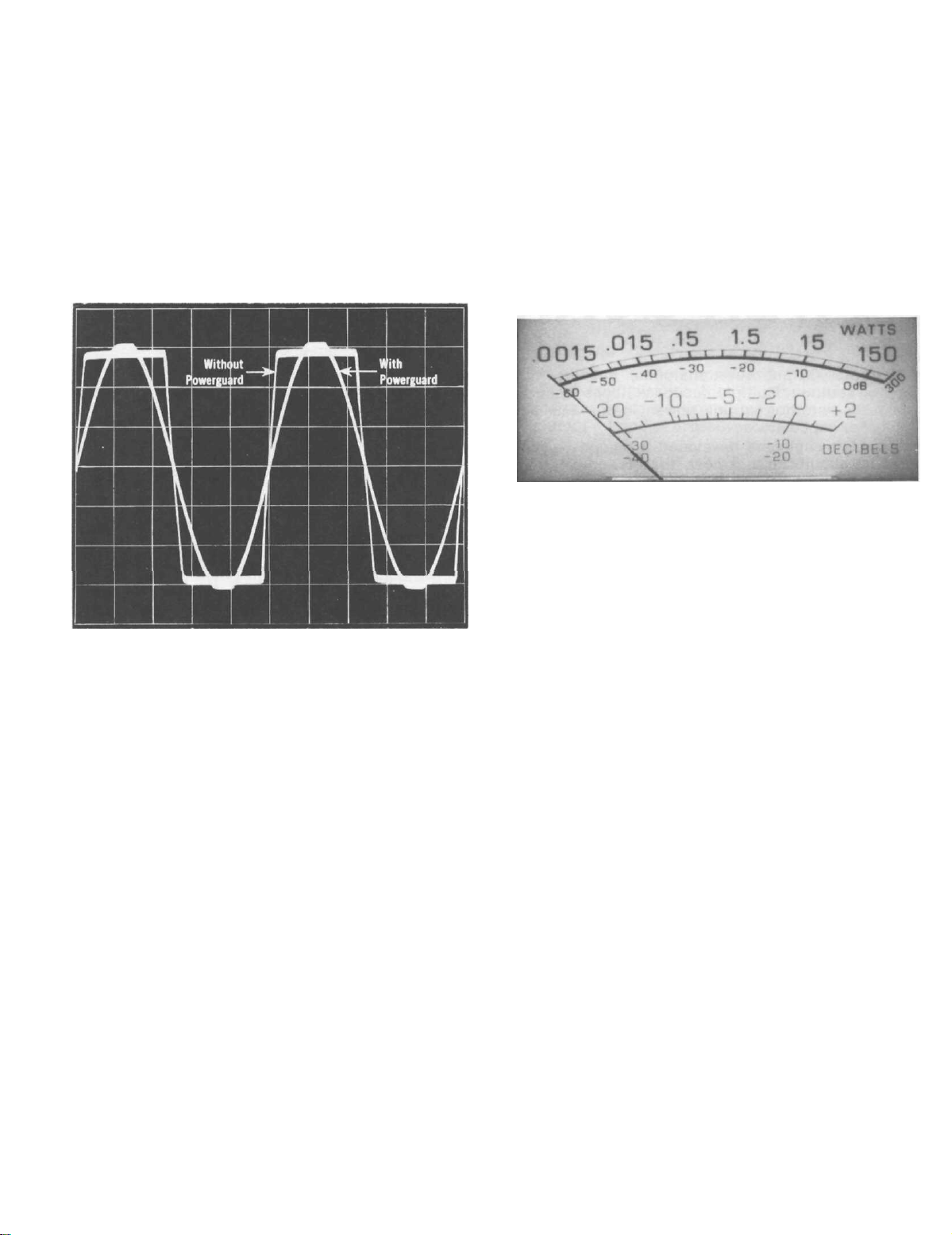
Oscillogram of output waveform with and without Power Guard.
Input overdriven for each trace 20 dB.
In only a fraction of a millisecond Power Guard
dynamically reduces input level to prevent amplifier
overload yet permits the amplifier to deliver its absolute maximum power output without extra distortion. In addition, the output of the "waveform comparator" activates the front panel NORMAL and
LIMIT indicators.
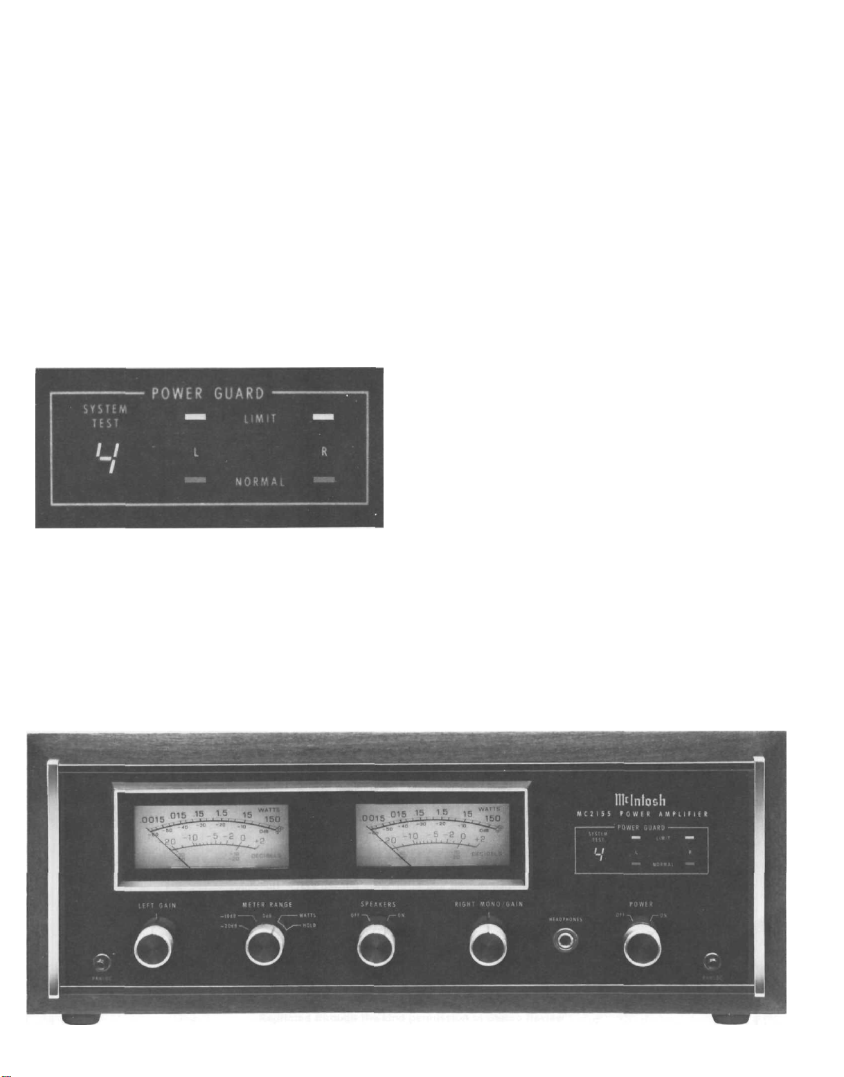
The Power Guard circuit provides a precise visual
indication when the amplifier has reached full power
output. Any time that the input circuit is fed excessive amounts of signal causing waveform differences through the amplifier of 0.5%, the output
mode indicators change from green NORMAL to red
LIMIT automatically and instantaneously. This warning persists long enough for positive visual indication of clipping for a pulse that is so infrequent or
short that it would be impossible to be seen even on
an oscilloscope. The indicators will illuminate on
clipping for a pulse as short in time as 100 microseconds. You are always assured that the power of your
amplifier is as clean and distortion free as it can be.
4
Mclntosh engineering pursued both problems
electrically by developing new electronic circuits
that cause the meters to respond to short interval information with an accuracy of 98%! To permit the
eye to see such high speed motion the electronic circuits that drive the meter pointer are time stretched
so the meter pointer position can register in the persistence of vision characteristics of the human eye.
The meters indicate directly in watts, or can be
made to hold the highest reading and continuously
update on higher power or can be switched to be
peak reading — peak locking decibel meters.
When used as a watt indicating meter all the information is direct reading, without conversions or
complicated mathematics. In addition, as direct
reading meters they are calibrated in average watts
for a sine wave signal but respond to signal peaks.
The meters indicate direct power in watts. They
are calibrated in average watts for a sine wave
signal but respond to signal peaks. So, a 200
average watt indication also means 400 instantaneous peak watts. The meters are voltage actuated and indicate power accurately when the
amplifier is operated into rated output load impedances.
Watts Hold, permits the meter to lock to and in-
dicate the highest power peak in a sequence of
peaks. The meter will be driven to maximum power
and electronically held there until a higher peak
passes through the amplifier. If no further peaks are
reached the meter needle will very slowly return to a
lower peak or to its rest position at a decay rate of 10
dB per minute.
The meters have extremely fast rise time, about
500 microseconds for 90% accuracy. A tone burst of
500 microseconds is almost inaudible even at full
power.
The meters are protected from damage in the
event of overloading in the wrong meter range.
AUTOMATIC TEST SYSTEM
The Automatic Test System provides positive protection and extends the long trouble free life of an
amplifier. Each time the amplifier is turned on an
Automatic Test System measures and verifies accurate performance at seven critical points in the
amplifier's circuits. The Automatic Test System
verification assures operational readiness before
operation starts and limits any damage should there
be component malfunction. Each time a test is
verified an LED number indicator shows which test
is being performed. An adjustable "beep" tone can
be heard with each test.
THE MCINTOSH OUTPUT CIRCUIT DESIGN
To achieve long trouble free life in an amplifier it
is essential to have cool operation. Cool operation
results from the careful design of the output circuit,
matching of the output circuit to the loudspeakers
with an autotransformer and a mechanical design
that permits the use of generous sized heat sinks
providing adequate ventilation without the use of
fans.
The bipolar eptaxial output transistors and the
Mclntosh output circuit allows the amplifier to
operate as cool as possible. When there is limited
program demand on the amplifier only the optimum
number of output devices operate. When there is no
signal no output device is conducting. Conservative
Mclntosh engineering keeps operating temperatures
low assuring long life.
The interleaved multifilar wound Mclntosh design-
ed autotransformer transfers all the power you paid
for to all impedance taps. You are not power penalized for operating at an output impedance of less than
8 ohms. The Mclntosh autotransformer does its outstanding job without adding phase shift, limiting frequency response or power output. The distortion
through the autoformer is 0.003% at 20 Hz and
unmeasurable at higher frequencies. In short, the
Mclntosh autotransformer is the ideal answer to a
difficult problem.
If in the testing an unacceptable voltage is encountered, the LED numeric designation locks to
isolate the faulty circuit. Faulty circuit identification
permits the service technician more efficient repair.
Without the Mclntosh Automatic Test System attempts to locate a fault by the probing and testing
needed, will often create additional problems by put-
ting undue mechanical and electrical stress on the
circuit components. The Automatic Test System protects your investment.
Heat sinks must be large and they must have adequate ventilation for effective cooling. For example
the MC 2255 has 1100 square inches (7.64 square
feet) of radiating surface. In addition, the chassis
has been designed to permit the maximum amount
of air to flow over the heat sinks to conduct away the
life limiting heat.
Mclntosh amplifiers provide the correct connection impedance to drive numbers of speakers simultaneously. For instance the 1 ohm output will drive
eight 8 ohm speakers and deliver full power without
overheating.
MC 2155 shown in optional walnut veneer cabinet.
5
test reports
"Reprinted with permission from the June 1982 issue of STEREO REVIEW magazine.
Copyright © 1982 Ziff-Davis Publishing Company. All rights reserved."
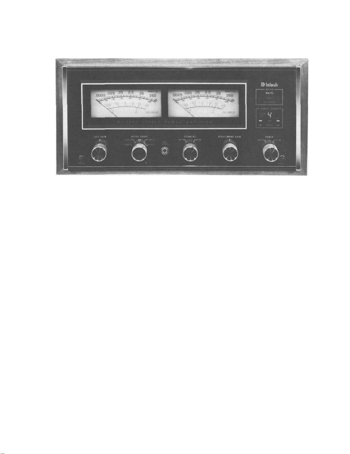
Mclntosh MC 2255 Power Amplifier
• Mclntosh MC 2255 Power Amplifier
• Power Rating: 250 watts per channel
• Size: 16¼ x 14¾ x 7¼ inches
• Weight: 82 pounds
• Price: $2,750
HE Mclntosh MC 2255 basic power am-
T
plifier is rated to deliver its output into
loads of 1, 2, 4, or 8 ohms, from 20 to
20,000 Hz, with no more than 0.02 per cent
harmonic or intermodulation distortion. Its
stereo outputs may be paralleled or bridged
to drive a mono load with a maximum output of 500 watts at 0.02 per cent distortion.
Depending on the connection used, the
mono load impedance can be from 0.5 to 16
ohms.
The unusual load capabilities of the MC
2255 derive from the use of large autotransformers to match the output transistors to
their loads. Like vacuum-tube amplifiers,
the MC 2255 has output terminals designated for 1, 2, 4, or 8 ohms. Thus, regard-
less of the speaker impedance, the output
transistors are optimally loaded and can deliver
their
full
power
without
and
excessive
driver
tortion or overheating.
The output stages of the MC 2255 operate in class-B, but a unique biasing system
completely eliminates the crossover distortion usually associated with class-B operation. This being the most efficient mode of
linear amplifier operation, the total power
consumption of the MC 2255 from the 120volt a.c. line is only 0.7 ampere at idle (or
normal playing volume) and 12 amperes at
full
output.
form a complete class-AB low-power amplifier which drives the front-panel headphone
The
input
dis-
stages
jack as well as the power stages. Switches
connect the input sections for mono operation.
In the
right-channel input drives both output sections
mode the other input section is used as a
phase inverter so that the outputs can be
driven 180 degrees out of phase.
The power stages are protected by a novel
Power Guard circuit that makes it impossible to clip the amplifier output by overdriving it. A waveform comparator monitors the
input and output signals of the amplifier,
and if the output waveform differs from the
input by an amount corresponding to about
0.5 per cent harmonic distortion, a red LIMIT light glows on the panel (there are separate lights for the two channels). Any further increase in the drive level causes the
signal to be attenuated ahead of the output
section. This prevents the output from ever
exceeding its linear operating range (according to McIntosh, the amplifier can be
overdriven by 20 dB before distortion
reaches 2 per cent).
Internally, the McIntosh MC 2255 is a
very complex amplifier, containing some
eighty-five transistors, forty-seven diodes,
and fourteen integrated circuits. Many of
its components are involved in the protective systems and in its novel self-test feature. Each time the amplifier is turned on,
an automatic seven-step test sequence
checks the key operating voltages for cor-
rectness. As each step is executed, the corresponding numeral lights up on a frontpanel display and a green light signals that
it has been passed. If any stage of the test is
not satisfactory, its number remains lit to
in
phase,
MONO/PARALLEL
and for the
MONO
mode
BRIDGE
the
indicate the problem area. Two different
test speeds can be selected, and one can
choose to have a "beep" sound after each
step or to have the tests proceed in silence.
Two large meters are calibrated logarithmically from less than 2.5 milliwatts to 500
watts output (because of the output transformers, these readings are equally applica-
ble to any of the load impedances for which
the amplifier is designed). Another scale
reads in decibels from -20 to + 2 (the latter corresponding to about 250 watts output). Knobs below the meters control LEFT
GAIN, RIGHT/MONO GAIN, METER RANGE
(-20 dB, -10 dB, 0 dB, WATTS, HOLD),
the SPEAKERS outputs, and POWER. The
HOLD position of the METER RANGE switch
causes the meters to retain their highest
readings. The meter-driving circuits allow
them to respond to very short program
peaks, although they are calibrated in aver-
age watts.
At the right side of the panel are the two
indicator groups.
shows the number of the SYSTEM TEST sequence step as it is executed, and pairs of
red and green LEDs show either that the
LIMIT
(of
or that the amplifier operation is NORMAL.
Above this group, a meter group illuminates
the words WATTS, HOLD, or DECIBELS, according
to the
switch.
On the rear of the chassis are two sets of
barrier terminal strips for the speaker outputs, a single unswitched a.c. outlet, and the
holder for the 15-ampere line fuse. A threeposition MODE switch selects STEREO, MONO
BRIDGE,
or
The
POWER GUARD
output power)
setting
of the
MONO PARALLEL
has
been exceeded
METER RANGE
operation. Next
display
6
STEREO REVIEW
test reports
to the two input phono jacks is a switch that
sets the input sensitivity to either 0.75 or 2.5
volts for full output depending upon the associated equipment. (The latter is the normally preferred setting for most setups.)
The MC 2255 is a handsome and rugged
amplifier, following a long-standing McIntosh tradition in its styling and construction. The pane! and most of the top metalwork are finished in black, with front accents of silver and softly lit blue-green meters. The chassis is chrome-plated. Also furnished with the amplifier are side brackets
and hardware for the McIntosh Panloc system for custom installations.
Mclntosh MC 2255
Power Amplifier
• Comment. Mclntosh (one of the oldest names in hi-fi, and perhaps the only
firm from its time to remain under the
original ownership) has earned an impressive reputation for their continued
support of their products, their exceptionally conservative design and specifications, and generally outstanding quality The MC 2255, the first McIntosh
product we have reviewed in many
years, is a perfect example of the continuation of those policies.
In its circuitry and operating features,
the MC 2255 is quite unlike any other
basic power amplifier we have seen. By
using autotransformers to match the
load impedance to the transistor requirements, McIntosh has made an amplifier
capable of delivering its full potential
performance into almost any load impedance it might encounter. That performance, as our tests have shown, is absolutely first-rate. It is difficult to imagine any home installation needing more
• Laboratory Measurements. Preconditioning the MC 2255 at one-third rated
power made the heat sinks very hot, but the
rest of the amplifier remained comfortably
cool throughout our tests. In normal opera-
tion the MC 2255 is no more than faintly
warm and has no need of a cooling fan or
any unusual ventilation precautions
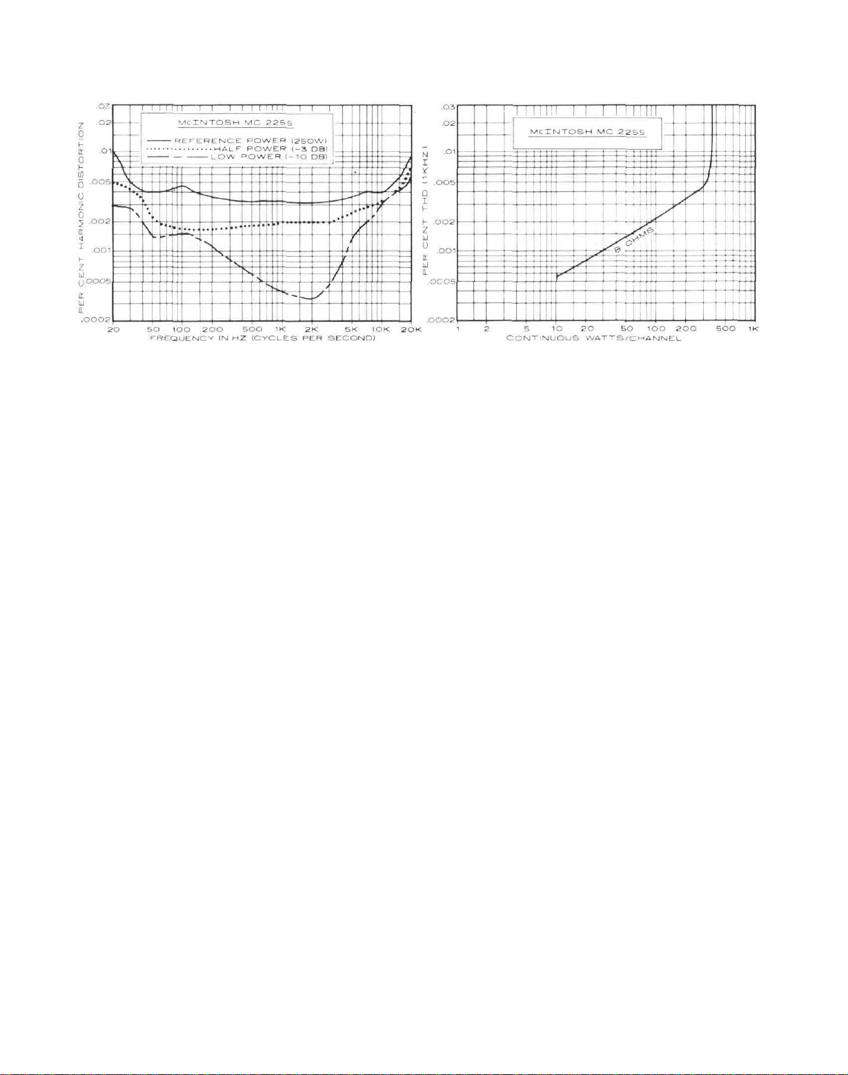
With both channels driving 8-ohm loads
at 1,000 Hz the distortion was undetectable
(well below the noise level) until we reached
10 watts output, when it measured 0.00056
per cent. It increased very gradually with
higher power to 0.0032 per cent at 250
watts and 0.0045 per cent at 300 watts. The
power than the MC 2255 delivers with
such apparent ease. Its noise, distortion,
stability, and any other quality one
might name are quite literally "state of
the
art."
The Power Guard system is most ef-
fective in making it impossible to hardclip the output of the amplifier. Regard-
less of how hard it is driven, it simply
cannot develop an audible amount of
distortion on musical program material
(2 per cent is well below the probable
threshold of audibility of distortion in a
music system being driven to 350-plus
watts). This feature should also mean a
greatly reduced likelihood of blowing
out a speaker, since clipping is a com-
mon cause of tweeter damage. For the
nontechnical user, the self-test feature is
mostly a "security blanket," although
we can appreciate that it would also simplify troubleshooting and servicing.
LEARLY, no effort has been spared in
c
the design and construction of this am-
plifier. This sort of perfectionism carries
a considerable price, both in dollars and
pounds (avoirdupois, not sterling!). Considering the probable long life of the MC
2255, that price does not seem at all
unreasonable
-Julian
D.
Hirscti
maximum power (corresponding to "clip-
ping power," except that the waveform
could not be made to clip) was about 357
watts, with distortion reading 0.24 per cent
at the limiting point. The output into 4
ohms (using the appropriate output terminals) was also 357 watts, and we were able
to develop 420 watts per channel into 2-ohm
loads.
At the rated 250 watts output into 8
ohms, the maximum distortion was 0.01 per
cent at 20 Hz. Over most of the audio range
it was about 0.004 per cent, rising to 0.009
per cent at 20,000 Hz. At lower power outputs the distortion was substantially lower.
The amplifier sensitivity (using the 2.5-volt
switch setting) was 0.15 volt for a 1-watt
reference output, and the A-weighted noise
and hum level was 86 dB below 1 watt. The
frequency response of the amplifier was
within +0. - 0 1 dB from 20 to 20,000 Hz
and was down 0.9 dB at 5 Hz and 3 dB at
150
kHz.
The amplifier rise time was about 3 mi-
croseconds, and its IHF slew factor was
about 10 The IHF intermodulation distortion, measured with 18- and 19-kHz signals, was — 94 dB for the second-order component at 1,000 Hz and -67 dB for each of
the third-order products at 17 and 20 kHz,
all being referred to a 250-watt level.
The clipping headroom of the amplifier
was 1.55 dB for 4- and 8-ohrn loads and
2.55 dB for 2-ohm loads. The dynamic power output was 455 to 466 watts, depending
on the load impedance, giving dynamicheadroom ratings of 2.65, 2.7, and 2.5 dB
for loads of 8, 4, and 2 ohms, respectively.
The meters read quite accurately (about
0.2 dB high at full power) and responded to
very brief transient signals. They are driven
from the class-AB input amplifier instead
of from the output stages as in most amplifiers, so the meter readings are unaffected
by switching off the speakers. We found the
headphone volume to be only marginally
useful with 600-ohm phones. It was adequate with conventional-impedance phones.
Reprinted through the kind permission of Stereo Review
STEREO REVIEW
7
Output Transformers
in Transistor
Power Amplifiers
by Sidney Corderman*
Output transformers can make transistor power amplifiers more reliable,
more flexible, and more powerful. At
the same time output transformers
offer the best continuous protection
to loudspeakers against the hazards of
avalanche failure of output transistor
devices.
Time has shown that output transformers make transistor amplifiers
operate cool and safe. The output
transformerless amplifier (OTL)
becomes less exciting when amplifiers
must give long, consistent and predictable operation.
Let's take a look at transformers in
general at their past and present
use in amplifiers - - - and at why
Mclntosh Laboratory continues to be
the leader in the amplifier field with
the use of transformers.
Remember Vacuum Tube Amplifiers?
Until the early 1960's, McIntosh
and just about everyone else in the
high fidelity component manufacturing business produced vacuum tube
power amplifiers exclusively. The
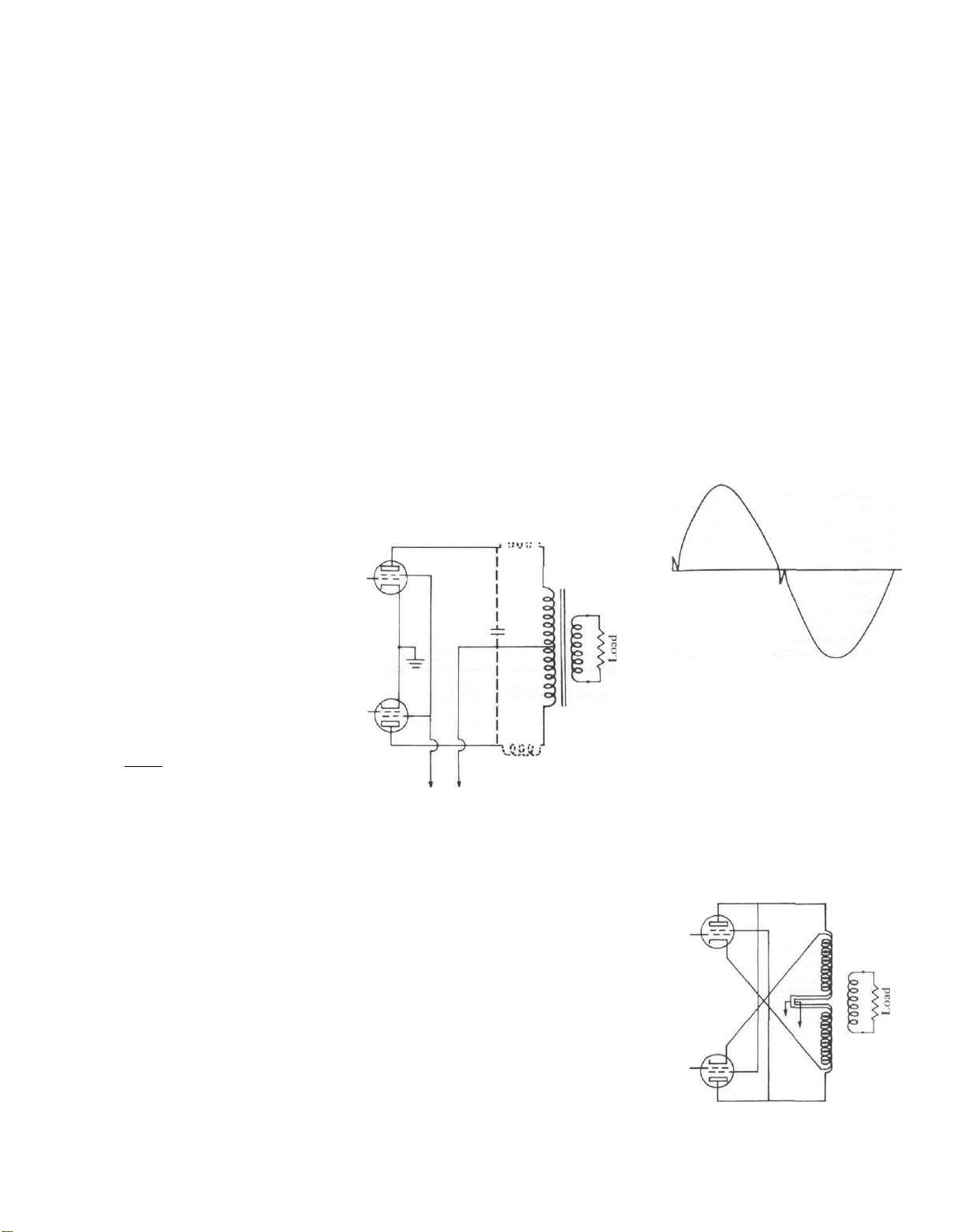
familiar push-pull circuit of Fig. 1
reigned supreme. In that circuit we
had a pair of tetrode or pentrode tubes
with their high output impedance try-
ing to deliver power to low impedance
loudspeaker systems. A transformer
was needed to provide the necessary
impedance match between them. But
there were problems in trying to
achieve an optimum transfer of power
between tubes and speakers. Typically,
using a pair of 6L6 output tubes in
push pull, we had a tube load imped-
ance of 4000 ohms trying to deliver
Fig. 1 — Typical push — pull output circuit
(see story tor dashed line information)
power to, say, an 8 ohm speaker load.
The impedance ratio was 500 to 1,
and the necessary transformer had to
have a turns ratio of around 23 to 1
(turns ratio varies as the square root of
the impedance ratio). The required
turns ratio created problems at both
ends of the audio frequency spectrum.
Leakage inductance and shunt capacitance (represented as dashed lines in
Fig. 1) caused high frequency roll-off.
The primary inductance of the transformer together with its inherent nonlinear characteristics placed limits on
low-frequency response. And the
energy stored in the unwanted leakage
inductance caused notch distortion, as
illustrated in Fig. 2.
Fig. 2 - Notch distortion in a typical Class B
The McIntosh Unity Coupled Circuit
Long before the advent of transistorized power amplifiers, McIntosh
found an effective way to solve these
problems. We called it the Unity Coupled Circuit. The basic configuration
is illustrated in the diagram of Fig. 3.
Fig. 3 — McIntosh "notch free" low
distortion Unity Coupled Circuit
output circuit
*
Vice President of Research and Development, McIntosh Laboratory Inc.
8
The impedance ratio required between
primary and secondary has been reduced by a factor of four-to-one compared with the conventional arrangement. It is now 125 to 1 (1000/8).
The turns ratio is therefore only half
of what it was before. Leakage inductance is therefore much lower, and so
is the shunt capacitance across the
windings. The use of a bifilar winding
technique completely eliminates the
leakage inductance problem of cou-
pling between the sections of the primary windings. It was the development of the Unity Coupled Circuit
by McIntosh (the circuit is patented)
way back in 1947 that enabled us to
produce amplifiers which were a whole
order of magnitude lower in distor-
tion than the competition of those
days. Typically, we were able to produce power output circuits with total
harmonic distortion of under 1.0%
even before the distortion-reducing
negative feedback loop was added.
With just 20 dB of feedback applied,
the THD was further reduced to under
0.1%!
What About Transistor Amplifiers
The audio industry welcomed the
power output transistor as the solution
to all its problems. After a few falter-
ing starts (early germanium power
output transistors were notoriously
unreliable and easily destroyed by high
operating temperatures), silicon power
transistors became the standard power
device in power amplifiers.
Since power output transistors exhibit a low output impedance, it was
possible to design output circuits to
match 8-ohm loads directly—without
the need for a matching audio output
transformer. Indeed, most OTL amplifiers, when coupled to 8-ohm resistive
loads for test purposes, can deliver full
rated power to those loads for long
periods of time without overheating or
exceeding safe thermal dissipation
limits. The trouble is that we don't
listen to resistors we listen to loudspeakers. It will come as no surprise to
you to learn that speakers having a
"nominal" impedance of 8 ohms often
measure lower and higher impedance
values at different audio frequencies.
Then, too, consider the fact that many
popular speaker systems have nominal
impedances of 4 ohms, and the imped-
ance of 4 ohm speakers can easily dip
down to as low as 2 ohms at certain
frequencies. What happens to an OTL
amplifier with such low impedances
connected to it? In theory, if an out-
put stage is designed to match an 8
ohm impedance, its power "output
capability should double when it's
connected to a 4 ohm impedance. But
as this mismatch occurs, thermal dissipation increases rapidly. In fact,
operating into a 4 ohm load, heat dissipation is double what it would be
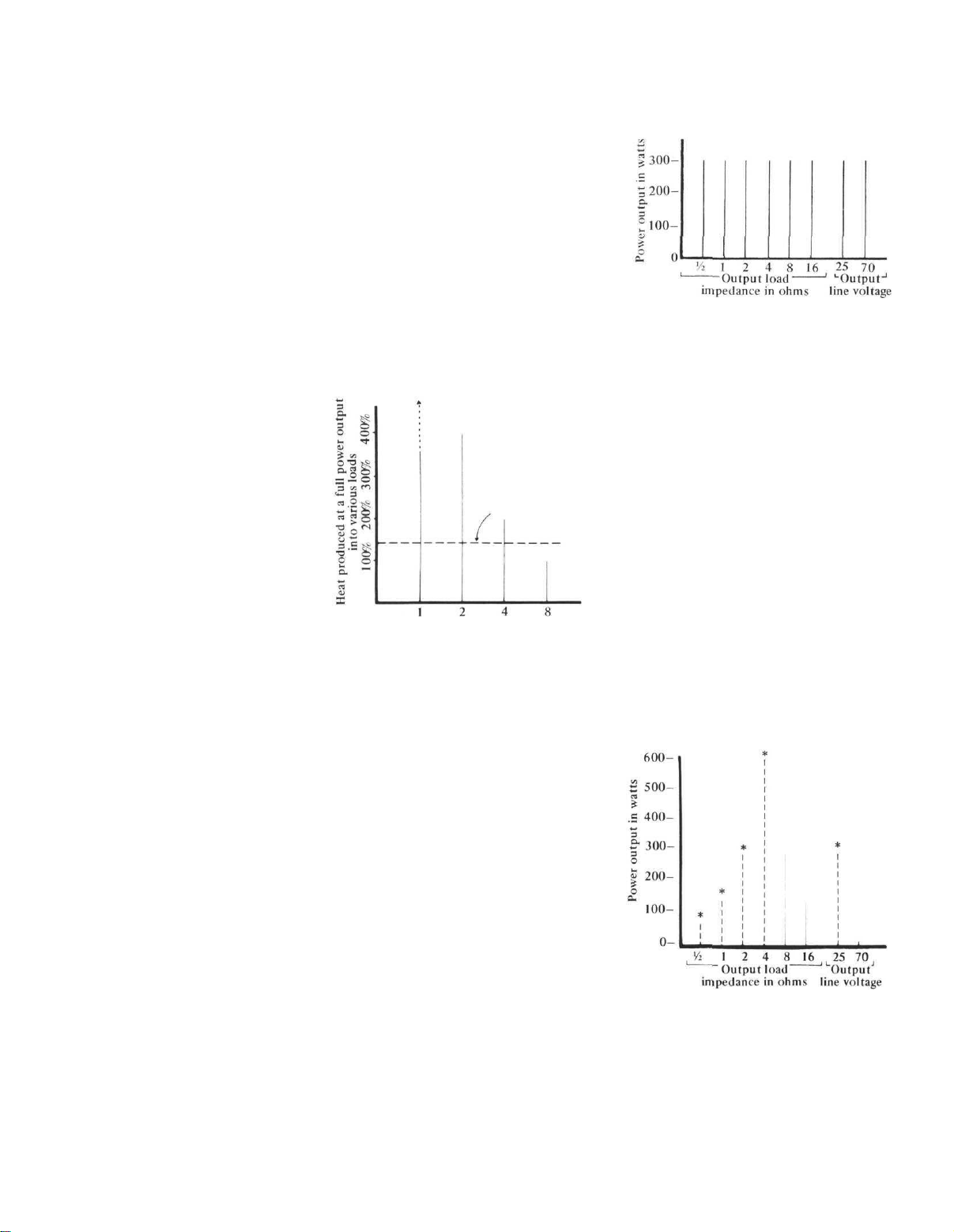
when operating at 8 ohms, as illustrated in Fig. 4. Unfortunately, if the
amplifier was designed for 8-ohm oper-
ation, its thermal dissipation limits
were designed with some safety factor
Heat dissipation
capacity required to
meet FTC rating
at 8 ohms.
Load impedance in ohms (1000%=Heat
produced at rated output into 8 ohms.)
Fig. 4 - Heat produced by transformerless
amplifier at various load impedance
for 8 ohm operation, so as to meet the
new FTC preconditioning requirements. These call for the amplifier to
be able to deliver one-third rated
power at rated impedance for one
hour. But, as you can see from Fig. 4,
the safety margin is not nearly great
enough to permit operation at 4-ohms
—or 2-ohms-or 1-ohm impedances.
Remember, too, that many amplifiers
and receivers have provisions for connection of more than one pair of
speakers for use in different listening
rooms, so that even if 8-ohm speakers
are selected, using double pairs of
them results in a 4-ohm net nominal
impedance even before allowing for
downward variations in impedance
at specific frequencies in the audio
spectrum. So, unless manufacturers are
willing to resort to disproportionately
massive heat sinks, cooling fans or
combinations of both, designing power
amplifiers that can deliver their maxi-
mum powers at both 8 ohms and im-
pedances of 4 ohms and lower becomes physically impractical in the
case of the OTL amplifiers.
Fig. 6 - Performance of MC 2300
The Answer-Output Transformers!
If a transistorized amplifier were
equipped with an output transformer,
you could move up or down in load
impedance and maintain full power
ratings without over-dissipating anything, since the amplifier's output
stages would always be working into
an ideal load.
To many hi-fi enthusiasts, output
transformers tend to create visions of
compromised design. That is just not
the case today. Technology in materials and transformer design methods
have advanced significantly in recent
years and, remember, we're dealing
with low impedance devices-not tubes.
It's no longer necessary to translate
impedances from a "plate circuit" to a
speaker-a step down of several hun-
(* - - - Continuous operation not possible
due to overheating. Protection circuit is assumed to current limit when load falls below 4 ohms, in actuality the output into 4
ohms and lower impedances will fall below
the values shown.)
Fig. 7 - Performance of non McIntosh
transformerless amplifier rated for
300 watts in 8 ohm load
9
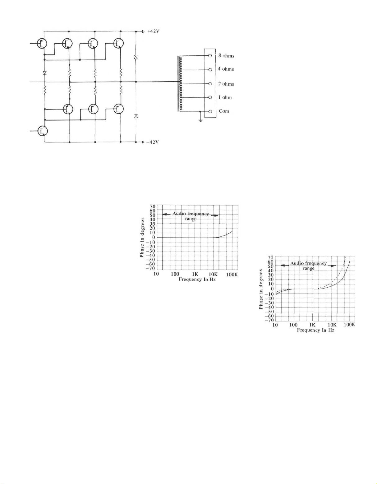
Fig. 5 - McIntosh MC 2205 output stage and transformer
dred to one. With transistor output
stages, a ratio of only about 4 to 1 is
required. In tube amplifiers, extremely
good balance in the push-pull primary
was required if notch distortion was to
be avoided. Now, using a single ended
push-pull transistor output stage the
transformer can be driven in a single
ended fashion. One end of the winding
Is returned to ground potential. With
the transformer at ground, no isolation
is required between the input and output and therefore a simple auto-
transformer can be used.
Fig. 5 shows a typical arrange-
ment used in our new MC 2205 amplifier. The output stages are designed to
work optimally into a load impedance
of 2.1 ohms and it becomes a simple
matter to "tap into" the auto-trans-
former for that precise impedance
match. Taps for 1 ohm, 2 ohm, 4 ohm
and 8 ohm operation are arranged so
that the output transistors continue to
work into their optimum impedance.
The result: full power output at any of
these impedances, with no possibility
of thermal over-dissipation.
Our popular MC 2300 amplifier
also uses an auto-transformer and
Fig. 6 shows how that amplifier is able
to deliver its full rated power (300
watts RMS per channel) into any
impedance from 0.5 ohms to 16 ohms,
as well as to 25 volt and 70 volt multispeaker system taps on the transformer. If we compare these results with
those obtained with a similarly rated
Fig. 8A - Typical of phase shift in
McIntosh auto-transformer at 8 ohms
OTL amplifier (Fig. 7) we see that at
all but 8 and 16 ohms, continuous
operation at theoretical maximum
power is impossible because of overheating and protection circuit limiting. Operation at 16 ohms, though
possible, is limited to a maximum
power output of 150 watts, in this
case, while operation into a 70-volt
line is impossible because of limitations in power supply voltages.
What About Phase Shift?
Critics opposed to the use of transformers in output circuits of audio
amplifiers arc quick to point out that
"transformers introduce phase shift"
at the low and high frequency extremes. As a matter of fact, a properly
designed transformer (and we'll get
into some of the factors that are involved in designing McIntosh output
transformers in a moment) can introduce about 3 degrees of phase shift at
20 kHz (Fig. 8A), which is certainly
insignificant. The typical volume control used on amplifiers (both those
that are OTL and those equipped with
transformers) introduce more shift
than that— about 20 degrees in fact
(Fig. 8B). Since an output transformer
is driven from an extremely low impedance, there is actually more lowfrequency phase shift caused by the
usual input coupling capacitor at these
low frequencies than by the trans-
former.
So, why haven't more manufacturers used output transformers on solidstate amplifiers? Possibly they are not
aware of the technology, but more
likely they don't want to spend the
extra cost. A good transformer is an
expensive component. It is heavy,
takes up a fair amount of space and
contradicts the audiophile's notion
that transistorized equipment must be
small and lightweight. Be that as it
may, the FTC regulations suggest that
output transformers are the only logical solution to rating audio amplifiers
honestly at 4, 8, 16 or any other
impedance required.
1 watt, 8 ohms
— Volume Control Clockwise
— Volume Control 12 o'clock
Fig. 8B - Typical phase shift
in a complete Mclntosh amplifier
Not Just Any Transformer!
At Mclntosh, we wind all our own
output auto-transformers. Of course,
we could purchase them from any one
of a number of transformer companies
who do nothing but wind transformers
(our power transformers are, in fact,
purchased from other suppliers), but
we have long since found that trans-
formers can't always be made successfully "according to the book". A great
deal of experimentation is required before a new design of a transformer can
10
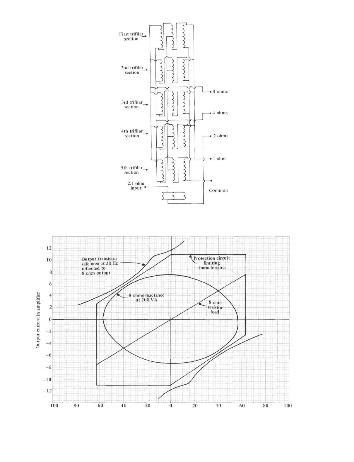
be mated to a specific amplifier circuit. We went through dozens of developmental samples in the case of our
new MC 2205 amplifier. What we
ended up with it shown schematically
in the diagram of Fig. 9. The transformer is trifilar wound to provide
coupling between sections. It takes 23
individual windings to make this output transformer. There are five different winding sections, all five of which
are connected in parallel. We use
grain oriented silicon steel core laminations because that kind of core means
less iron-and less iron in turn means
tighter coupling. It also means lower
winding resistance for a given size
wire. The grain oriented silicon steel
means that it has a higher magnetic
saturation point-about 17 kilogauss
versus 12 to 13 kilogausses for the
non-oriented variety. There is therefore less core loss, or, to put it simply,
we end up with a more efficient transformer-one which couples more of
the available amplifier power to the
speaker loads. To further improve coupling, we don't use any interlayer in-
sulating paper in a power transformer
that might pose a breakdown problem.
But since our polyurethane insulated
Fig. 9 - MC 2205 output
auto-transformer schematic diagram
wire is rated at 4000 volts per mil (and
since the highest voltage we're talking
about for an audio transformer is
about 56 volts), this really is no prob-
lem at all. All of our output trans-
formers arc potted with material
which has especially high thermal
conductivity. Besides helping to keep
operating temperatures within the
transformer down, this compound reduces lamination buzz to inaudible
levels. We figure you'd rather listen to
your speakers than to our transformers!
Our Transformers Are Only Part
of The Story
Whether an amplifier uses an out-
put transformer or not, its output de-
vices must be designed to work into an
optimum load so that maximum cur-
rent delivered by the output transis-
tors never exceeds the safe operating
area specified for the transistor. Fig.
11 shows current versus voltage limita-
tions for the epibase type of output
transistor used in our MC 2205 ampli-
fier. If all amplifier loads were purely
resistive, staying within the safe oper-
ating area would be relatively simple,
but the fact is that speakers often pre-
Output volts
Fig. 10-Load and limiting data of
the McIntosh MC 2205 measured at 8 ohm output
11
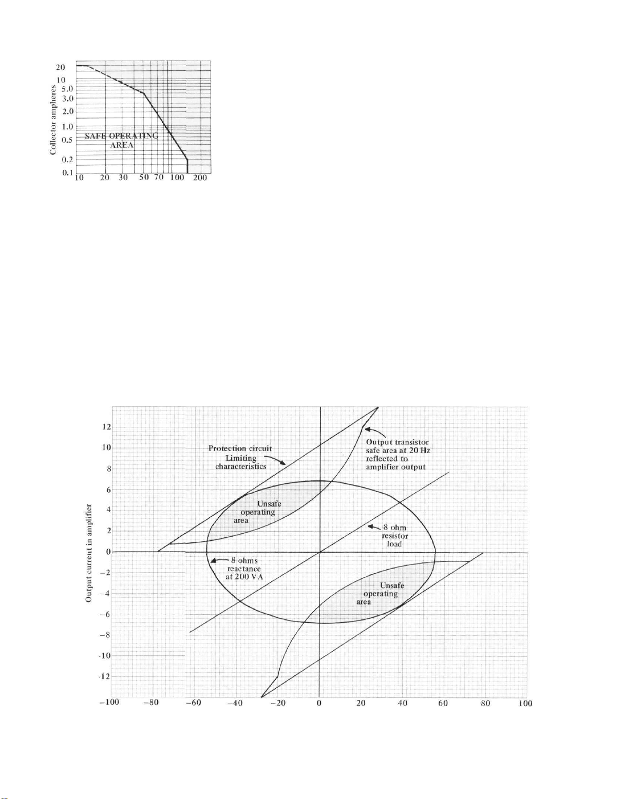
Collector volts
Fig. 11 - Current versus voltage
limitation epibase type
output transistor
fiers. In Fig. 10 we have combined the
safe operating diagram of Fig. 10 with
load and limiting characteristics at the
8-ohm tap of our MC 2205. As you
can see, even when the load is totally
reactive, every possible voltage and
current condition falls within the
safe operating area of the output de-
vices used. Compare this diagram with
Fig. 12 derived from data concerning
the output transistors used in a currently available high-powered amplifier.
Note that inadequate protection is
provided for reactive loads.
To Sum It All Up
The points we've tried to make are
relatively few, but they spell the differ-
ence between a McIntosh output-
transformer equipped amplifier and
every other kind of amplifier around.
1. A transformer equipped amplifier will deliver rated power at any impedance for which a transformer tap
is provided.
2. An OTL amplifier designed for
8-ohm operation cannot operate safely
(according to the FTC rules) when
driving lower impedances (4 ohms,
2 ohms, etc.), yet such loads commonly occur either because of speaker im-
pedance variations with frequency or
because of paralleling of multiple
speaker systems across one channel
of an amplifier.
3. The new FTC power rule regarding audio amplifiers has forced many
manufacturers to omit 4-ohm ratings even though 4-ohm speakers arc in
common use. McIntosh transformerequipped audio
amplifiers
deliver
full
power at any impedance for which a
transformer output tap is provided.
4. Because of their design, McIntosh
transformers introduce less series leakage inductance than is commonly encountered with OTL amplifiers which
require a series inductance between
the output circuit and the speaker connection for amplifier stability. At the
8 ohm tap of our MC 2205, leakage inductance is a low 3.5 microhenries.
This represents an impedance of only
2.2 ohms at a frequency of 100 kHz.
5. Properly designed output transformers impose no limitations on frequency response. At the 8-ohm tap of
the MC 2205, response is down 0.3 dB
at 50 kHz. With a 4-ohm toad con-
nected, response is down 0.1 dB at
50
kHz.
6. Phase response of the MC 2205
amplifier, using its specially designed
output transformer, is accurate to
within 9 degrees at the 8 ohm tap at
a frequency of 50 kHz and undergoes
zero degrees of phase shift at 20 Hz.
At the 4-ohm tap, phase shift at 50 kHz
is only 7.2 degrees.
Next time anyone gets into an argument with you concerning the attributes of an OTL amplifier versus a
McIntosh transformer-equipped amplifier, you might let your adversary read
this story.
12
Output volts
a non McIntosh high-powered transformerless amplifier measured at 8 ohms output.
Fig. 12 — Load and limiting data of
You are Mclntosh protected
six ways with the new
Mclntosh amplifiers.
PROTECTION
1. The patented Mclntosh Sentry Monitoring circuit
constantly monitors the output signal. At signal
levels up to rated output this circuit has high impedance and has no effect upon the output. If the
power output exceeds design maximum, the Sentry
Monitoring circuit operates to limit the signal to the
output transistors. In the event of a short circuit
across the amplifier output or severe impedance
mismatch the Sentry Monitoring circuit will protect
the output transistors from failure. Both positive and
negative halves of the output signal are monitored
independently.
PROTECTION
2. Should the temperature of the heat sinks rise
above normal through restricted ventilation or other
causes, the AC Power is disconnected by an
automatic heat sensing relay. The AC power will be
restored when the temperature returns to normal.
PROTECTION
3. Any loudspeaker damaging DC component in the
output circuit, from whatever cause, is shunted to
ground through the Mclntosh autotransformer. You
and your speakers are protected completely from
this kind of amplifier failure.
PROTECTION
4. Mclntosh gives you a money back guarantee of
performance. Your Mclntosh instrument must be
capable of meeting its published performance limits
or you get your money back. No other manufacturer
offers you this money back guarantee of performance.
PROTECTION
5. The Mclntosh 3 Year Service Contract protects
you from the cost of repair for three full years
because Mclntosh will provide the service materials
and labor needed to return the measured performance to the original performance limits. The SERVICE CONTRACT does not cover any shipping costs
to and from the authorized service agency or the factory.
PROTECTION
6. The Automatic Test System provides positive pro-
tection and extends the long trouble free life of an
amplifier. Each time the amplifier is turned on seven
tests measure and verify accurate performance.
Automatic Test System protects by verifying circuit
readiness before operation starts. Each time a test
is verified a numeric indicator turns on to indicate
the test being performed. If in the test countdown an
unacceptable voltage is encountered, the numeric
designation locks to isolate the faulty circuit.
13
PERFORMANCE GUARANTEED
Performance limits are the maximum
deviation from perfection permitted for a
Mclntosh instrument. We promise you that
when you purchase a new Mclntosh product from a Franchised Mclntosh dealer it
will be capable of performance at or exceeding these limits or you can return the
unit and get your money back. Mclntosh is
the only manufacturer that makes this
statement.
POWER AMPLI
POWER OUTPUT STEREO
Minimum Watts,
Both Channels Operating
POWER OUTPUT MONO
Minimum Watts
POWER BAND WIDTH
TOTAL HARMONIC DISTORTION
Maximum, 250 mW to Rated
Power, 20 Hz to 20 kHz
OUTPUT LOAD IMPEDANCE
Stereo
Mono
INTERMODULATION DISTORTION
Maximum, 250 mW to Rated Power
FREQUENCY RESPONSE
20 Hz to 20 kHz
(at 1 Watt)
NOISE AND HUM
Below Rated Output
OUTPUT VOLTAGES FOR
DISTRIBUTION SYSTEMS
DAMPING FACTOR
INPUT IMPEDANCE
INPUT SENSITIVITY
POWER REQUIREMENT
AC Line Voltage - Frequency
Watts at No Signal
Watts at Rated Output
SEMICONDUCTOR COMPLEMENT
Transistors
Diodes
Integrated Circuits
SIZE
Panel Height
Panel Width
Depth
FINISH
MC 2500
500 Watts Per
Channel
1000 Watts
20 Hz to 20 kHz
0.02%
1, 2, 4, 8 W
1/2,
1, 2, 4, 8, 16 W
0.02%
+ 0.
-0.25
dB
-95 dB
25 Volts
greater than 30
50.000 W
0.75 or 2.5 Volts
120V, 50-60 Hz
75 Watts
1800 Watts
91
35
6
10-1/2" (26.7cm)
19" (48.3cm)
17" (43.2cm)
Gold and Black
Panel, Black
Knobs
Mclntosh audio power ratings are stated
in accordance with the Federal Trade
Commission Regulation of November 4,
1974 concerning power output claims for
amplifiers used in home entertainment
products.
14
WEIGHT
Net
In Carton
HEAT SINK AREA
SPECIAL FEATURES
Power Guard
Output Autoformers
Automatic Test System
Output Meters: Calibrated in Watts
Output Meters: Calibrated in dB
Thermal Turn-Off
Sentry Monitor
D.C. Speaker Protection
Output Limit Indicator
Panloc Mounting
Cooling: Convection
129#(58.5kg}
144#(65.3kg)
1990
sq. in.
X
N/A
X
X
X
X
X
X
N/A
N/A

FIER PERFORMANCE LIMITS
MC 2255
250 Watts Per
Channel
500 Watts
20 Hz to 20 kHz
0.02%
1, 2, 4, 8 W
1/2,
1, 2, 4, 8, 16 W
0.02%
+ 0,
-0.25
-95 dB
25 Volts
greater than 30
50,000 W
0.75 or 2.5 Volts
dB
MC 2250
250 Watts Per
Channel
500 Watts
20 Hz to 20 kHz
0.02%
1, 2, 4, 8 W
1/2,
1, 2, 4, 8, 16 W
0.02%
+ 0,
-0.25
-95 dB
25 Volts
greater than 30
50,000 W
0.75 or 2.5 Volts
dB
MC
2155
150 Watts Per
Channel
300 Watts
20 Hz to 20 kHz
0.02%
1, 2, 4, 8 W
1/2,
1, 2, 4, 8, 16 W
0.02%
+ 0,
-0.25
dB
-95 dB
25 Volts
greater than 30
50,000 Si
0.75 or 2.5 Volts
MC
2120
120 Watts Per
Channel
240 Watts
20 Hz to 20 kHz
0.1%
2, 4, 8, 16 W
1, 2, 4, 8 W
0.1%
+ 0,
-0.25
dB
-95 dB
25 Volts
14 to 50
100,000 W
0.75 or 2.5 Volts
MC 502
75 W/Chan. 2.7 to 4 W
50W/Chan. 8 W
150 Watts
into 8 Ohms
20 Hz to 20 kHz
0.02%
2.7 to 8 W
8 W
0.02%
+ 0,
-0.25
-95 dB
25 Volts (Stereo Only)
75,000 W
0.75 or 2.5 Volts
dB
>50
120V, 50-60 Hz
70 Watts
1440 Watts
85
47
14
7-1/8" (18.1cm)
16-3/16" (41.1cm)
14-1/2" (36.8cm)
Black Glass Panel,
Gold/Teal Nomen-
clature, Gold and
Black Knobs
82# (37.2kg)
96# (43.5kg)
1080
sq. in.
X
X
X
X
X
X
X
X
X
X
X
120V, 50-60 Hz
84 Watts
1440 Watts
76
37
9
6-31/32" (17.7cm)
16" (40.6cm)
14-1/2" (36.8cm)
Gold Panel
Gold and Black
Knobs
80# (36.3kg)
94# (42.6kg)
1080
sq. in.
X
X
X
N/A
N/A
X
X
X
X
N/A
X
120V, 50-60 Hz
84 Watts
720 Watts
81
47
14
5-7/16" (13.8cm)
16" (40.6cm)
14-1/2" (36.8cm)
Black Glass Panel,
Gold/Teal Nomen-
clature, Gold and
Black Knobs
65# (29.5kg)
77# (35kg)
772 sq. in.
X
X
X
X
X
X
X
X
X
X
X
120V, 50-60 Hz
50 Watts
460 Watts
39
24
2
5-7/32" (13.3cm)
16" (40.6cm)
14-1/2" (36.8cm)
Gold Panel,
Gold and Black
Knobs
57# (26kg)
70# (32kg)
772 sq. in.
X
X
N/A
N/A
N/A
X
X
X
X
N/A
X
120, 50-60 Hz
20 Watts
400 Watts
39
20
4
3-5/8" (9.2cm)
16" (40.6cm)
14-1/2" (36.8cm)
Black Glass Panel,
Gold/Teal Nomen-
clature, Gold and
Black Knobs
27# (12kg)
38#(17kg)
513 sq. in.
X
N/A
N/A
N/A
N/A
X
X
X
X
X
X
" 5
 Loading...