

Page 1
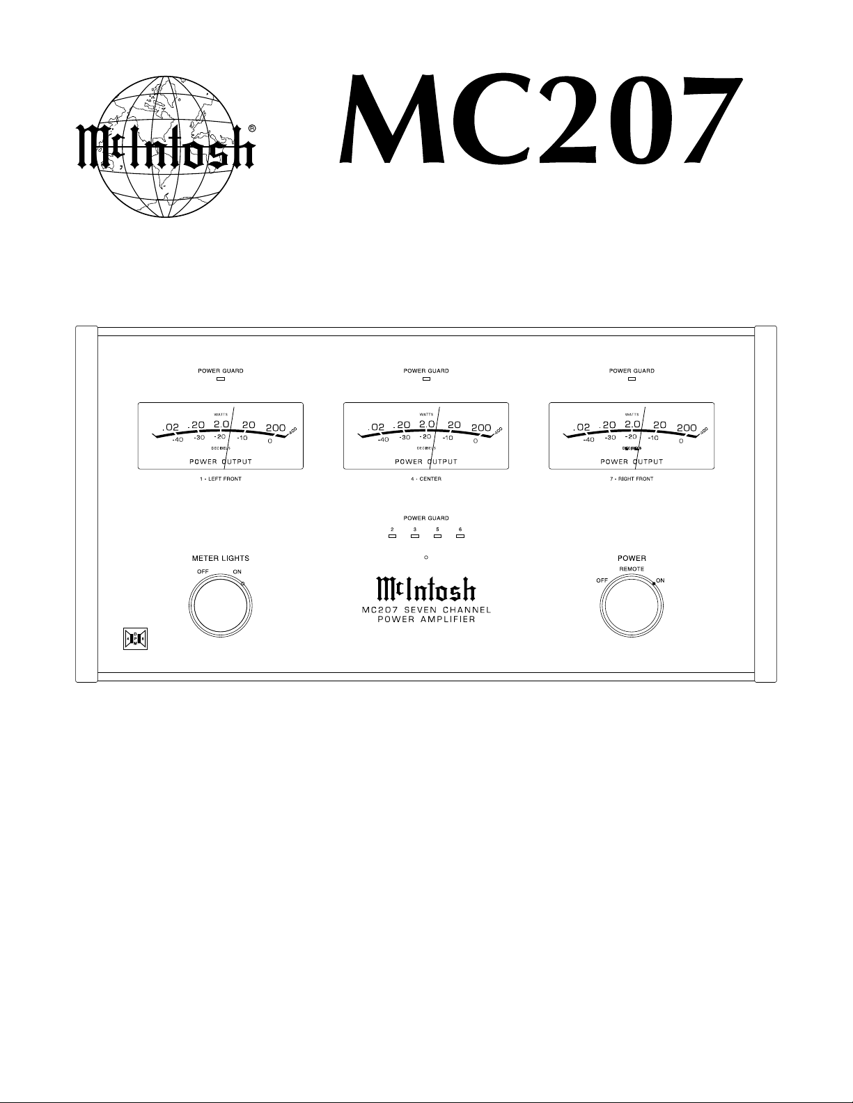
POWER AMPLIFIER
SERIAL NO. VQ1001 And Above
CONTENTS
Performance Specifications ........................................ 2
Notes ......................................................................... 2
Rear Panel .................................................................. 3
Section Location ........................................................ 5
Block Diagram ........................................................... 6
Interconnection Diagram ...................................... 7 - 8
Input Schematic and PCB .................................... 9 - 12
Heatsink 1-Channel Schematic and PCB ............ 13 - 18
SERVICE MANUAL
Serial Number VQ1001 And Above
Heatsink 2-Channel Schematic and PCB ............ 21 - 26
Display Schematic and PCB ............................... 29 - 32
Capacitor Schematic and PCB .................................. 33
Power Supply Schematic and PCB..................... 34 - 35
Parts List ............................................................ 36 - 42
Exploded Views and Parts Lists .......................... 43 - 46
Repacking Instruction .............................................. 47
Page 2

PERFORMANCE SPECIFICATIONS
Power Output
Minimum sine wave continuous average power output per
channel, all channels operating is: 200 watts into 4 ohm or
8 ohm load
Rated Power Band
20Hz to 20,000Hz
Total Harmonic Distortion
Maximum Total Harmonic Distortion at any power level from
250 milliwatts to rated power output is: 0.005% for 4 or 8
ohm loads
Dynamic Headroom
1.7dB
Frequency Response
+0, -0.25dB from 20Hz to 20,000Hz
+0, -3dB from 10Hz to 100,000Hz
Sensitivity
1.0 Volt Unbalanced with a 4 ohm Loudspeaker
2.0 Volt Balanced with a 4 ohm Loudspeaker
1.4 Volt Unbalanced with a 8 ohm Loudspeaker
2.8 Volt Balanced with a 8 ohm Loudspeaker
A-Weighted Signal To Noise Ratio
89dB (112dB below rated output)
Intermodulation Distortion
Maximum Intermodulation Distortion if instantaneous peak
output per channel does not exceed twice the rated output, for
any combination of frequencies from 20Hz to 20,000Hz, with
all channels operating is: 0.005% for 4 or 8 ohm loads
Input Impedance
20,000 ohms Balanced
10,000 ohms Unbalanced
Wide Band Damping Factor
Greater than 60 at 4 ohms
Greater than 140 at 8 ohms
Power Requirements
100 Volts, 50/60Hz at 1440 watts
110 Volts, 50/60Hz at 13.0 amps
120 Volts, 50/60Hz at 12.0 amps
220 Volts, 50/60Hz at 6.0 amps
230 Volts, 50/60Hz at 6.0 amps
240 Volts, 50/60Hz at 6.0 amps
Note: Refer to the rear panel of the MC207 for the correct voltage.
Dimensions
Front Panel: 17-1/2 inches (44.45cm) wide, 9-7/16 inches
(23.97cm) high. Depth behind front mounting panel is
18-3/4 inches (47.63cm), including clearance for connectors.
Weight
83 pounds (37.6kg) net, 116 pounds (52.6kg) in shipping carton
1. The heavy lines on the schematic denote the primary
signal path.
2. Unless otherwise noted, all voltages indicated on the
schematics are measured under the following conditions:
a. AC input at 120 volts, 50/60Hz.
b. All voltages are +/-10% with respect to ground. A
high impedance (10 megaohm) voltmeter must be used.
3. Unless otherwise specified:
a. Resistor values are in ohms.
b. Capacitor values are microfarads (uF).
c. Inductor values are in microhenries (uH).
NOTES
4. On PC board drawings, Square pad indicates:
a. Polarized Capacitors - Positive
b. Diodes - Cathode
c. Others - Pin 1
5. WARNING
Parts marked with the symbol have critical
characteristics. Use only replacement parts recommended by the manufacturer.
2
Page 3

REAR PANEL
MC207
3
Page 4

NOTES
4
Page 5
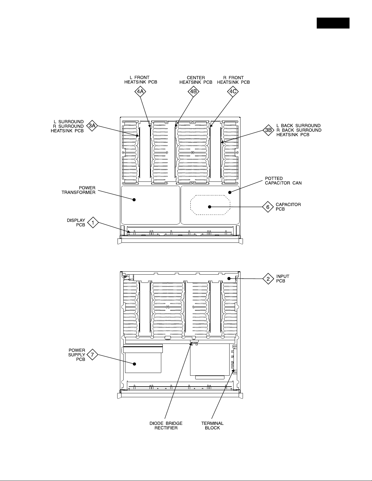
SECTION LOCATIONS
MC207
TOP VIEW
TOP VIEW WITH COVER REMOVED
5
Page 6
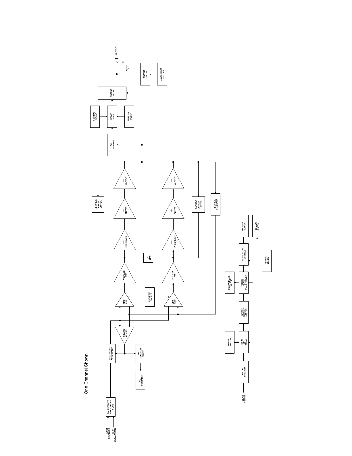
BLOCK DIAGRAM
6
Page 7
MC207
1
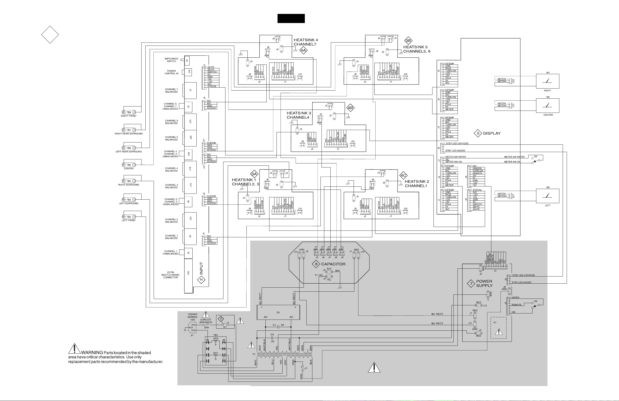
INTERCONNECT
7 8
Page 8

2
INPUT 050065
9 10
Page 9
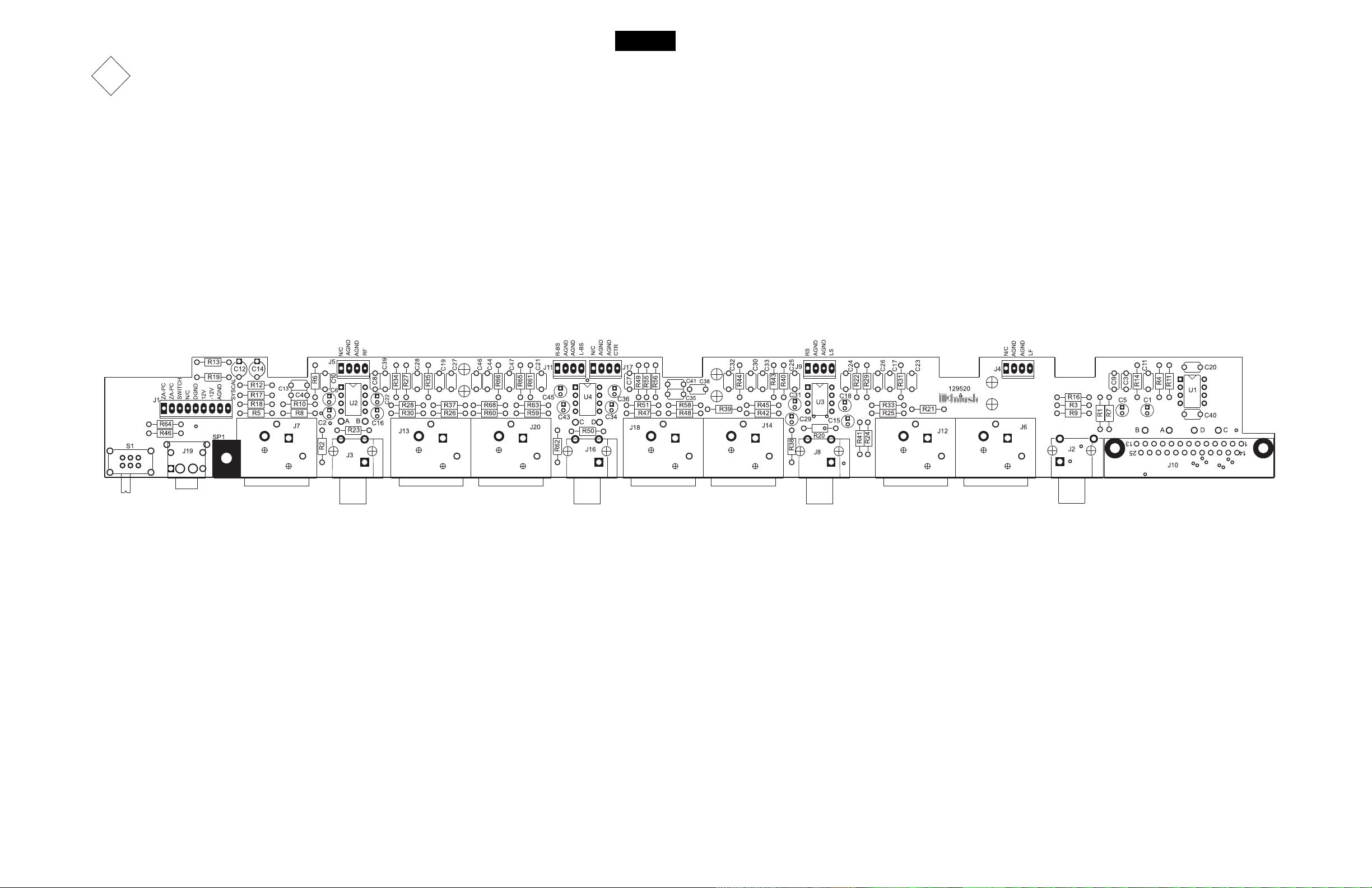
MC207
2
INPUT 050065
11 12
Page 10

3
A
B
HEATSINK 1-CHANNEL 050070
13 14
Page 11

3
MC207
A
B
HEATSINK 1-CHANNEL DRIVER SECTION 050070
15 16
Page 12

3
A
B
HEATSINK 1-CHANNEL 050070
* Denotes components on reverse or backside of PC Board.
17 18
Page 13

NOTES
MC207
19 20
Page 14

4
A
B
C
HEATSINK 2-CHANNEL 050064
21 22
Page 15

4
MC207
A
B
C
HEATSINK 2-CHANNEL DRIVER SECTION 050064
23 2524
Page 16

3
4
A
B
C
5
DISPLAY ILLUMINATION SECTION 050066HEATSINK 2-CHANNEL 050064
A
B
* Denotes components on reverse or backside of PC Board.
26 2827
Page 17

MC207
5
DISPLAY METER SECTION 050066
5
DISPLAY POWER GUARD SECTION 050066
29 30
Page 18

5
DISPLAY 050066
* Denotes components on reverse or backside of PC Board.
31 32
Page 19

MC207
6
CAPACITOR 050063
* Denotes components on reverse or backside of PC Board.
33
Page 20

7
POWER SUPPLY 050062
34
Page 21

MC207
7
POWER SUPPLY 050062
35
Page 22

PARTS LIST
Ref
No. Description
1
INTERCONNECT
C1 ASSEMBLY CAPACITOR 052005
C2 ASSEMBLY CAPACITOR 052005
D1 DIODE BRID RECT 070139
M1 METER MC207 124089
M2 METER MC207 124089
M3 METER MC207 124089
RT1 ASSEMBLY THERMISTOR 052017
RT2 ASSEMBLY THERMISTOR 052017
S1 SWITCH POWER 146243
S2 SWITCH POWER 146243
T1 POTTED TRANSFORMER POWER 050061
TB1 TERMINAL BLOCK AC 074091
TB2 POST BINDING DUAL 084124
TB3 POST BINDING DUAL 084124
TB4 POST BINDING DUAL 084124
TB5 POST BINDING DUAL 084124
TB6 POST BINDING DUAL 084124
TB7 POST BINDING DUAL 084124
TB8 POST BINDING DUAL 084124
2
050065 INPUT PCB
C1 CAP ELECT 10UF 16V 4X5 CASE 066382
C2 CAP ELECT 10UF 16V 4X5 CASE 066382
C3 CAP MONO 47PF 200V 10% NPO 061299
C4 CAP MONO 47PF 200V 10% NPO 061299
C5 CAP ELECT 10UF 16V 4X5 CASE 066382
C6 CAP ELECT 10UF 16V 4X5 CASE 066382
C7 CAP MONO .1uF 50V 20% Z5U 061305
C8 CAP MONO .1uF 50V 20% Z5U 061305
C9 CAP MONO 22PF 200V 10% NPO 061298
C10 CAP MONO 22PF 200V 10% NPO 061298
C11 CAP MONO 47PF 200V 10% NPO 061299
C12 CAP ELECT 10UF 50V 066445
C13 CAP MONO 47PF 200V 10% NPO 061299
C14 CAP ELECT 10UF 50V 066445
C15 CAP ELECT 10UF 16V 4X5 CASE 066382
C16 CAP ELECT 10UF 16V 4X5 CASE 066382
C17 CAP MONO 47PF 200V 10% NPO 061299
C18 CAP ELECT 10UF 16V 4X5 CASE 066382
C19 CAP MONO 47PF 200V 10% NPO 061299
C20 CAP MONO .1uF 50V 20% Z5U 061305
C21 CAP MONO .1uF 50V 20% Z5U 061305
C22 CAP ELECT 10UF 16V 4X5 CASE 066382
C23 CAP MONO 22PF 200V 10% NPO 061298
C24 CAP MONO .1uF 50V 20% Z5U 061305
C25 CAP MONO .1uF 50V 20% Z5U 061305
C26 CAP MONO 47PF 200V 10% NPO 061299
C27 CAP MONO 22PF 200V 10% NPO 061298
C28 CAP MONO 47PF 200V 10% NPO 061299
C29 CAP ELECT 10UF 16V 4X5 CASE 066382
C30 CAP MONO 47PF 200V 10% NPO 061299
C31 CAP ELECT 10UF 16V 4X5 CASE 066382
C32 CAP MONO 22PF 200V 10% NPO 061298
C33 CAP MONO 47PF 200V 10% NPO 061299
C34 CAP ELECT 10UF 16V 4X5 CASE 066382
C35 CAP MONO 47PF 200V 10% NPO 061299
C36 CAP ELECT 10UF 16V 4X5 CASE 066382
C38 CAP MONO 22PF 200V 10% NPO 061298
C39 CAP MONO .1uF 50V 20% Z5U 061305
C40 CAP MONO .1uF 50V 20% Z5U 061305
C41 CAP MONO 47PF 200V 10% NPO 061299
Part
No.
C43 CAP ELECT 10UF 16V 4X5 CASE 066382
C44 CAP MONO 47PF 200V 10% NPO 061299
C45 CAP ELECT 10UF 16V 4X5 CASE 066382
C46 CAP MONO 22PF 200V 10% NPO 061298
C47 CAP MONO 22PF 200V 10% NPO 061298
J1 CONN MALE 9 POS FRICTION LOCK 117244
J2 JACK RCA BLK 117847
J3 JACK RCA 1X2 BLK/BLK 14MM 117848
J4 CONN 4 PIN 117215
J5 CONN 4 PIN 117215
J6 RECEPTACLE XLR FEMALE 117685
J7 RECEPTACLE XLR FEMALE 117685
J8 JACK RCA 1X2 BLK/BLK 14MM 117848
J9 CONN 4 PIN 117215
J10 CONN D 25-PIN 117501
J11 CONN 4 PIN 117215
J12 RECEPTACLE XLR FEMALE 117685
J13 RECEPTACLE XLR FEMALE 117685
J14 RECEPTACLE XLR FEMALE 117685
J16 JACK RCA 1X2 BLK/BLK 14MM 117848
J17 CONN 4 PIN 117215
J18 RECEPTACLE XLR FEMALE 117685
J19 JACK HEADPHONE DUAL BLACK 1/8117825
J20 RECEPTACLE XLR FEMALE 117685
R1 RES MF 1K 1% 1/4W 144090
R2 RES MF 1K 1% 1/4W 144090
R3 RES MF 20K 1% 1/4W 144104
R4 RES MF 221 OHM 1% 1/4W 144172
R5 RES MF 20K 1% 1/4W 144104
R6 RES MF 221 OHM 1% 1/4W 144172
R7 RES MF 100K 1% 1/4W 144113
R8 RES MF 100K 1% 1/4W 144113
R9 RES MF 20K 1% 1/4W 144104
R10 RES MF 20K 1% 1/4W 144104
R11 RES MF 10K 1% 1/4W 144053
R12 RES MF 10K 1% 1/4W 144053
R13 RES MF 10 OHM 1% 1/4W 144157
R14 RES MF 10K 1% 1/4W 144053
R16 RES MF 100K 1% 1/4W 144113
R17 RES MF 10K 1% 1/4W 144053
R18 RES MF 100K 1% 1/4W 144113
R19 RES MF 10 OHM 1% 1/4W 144157
R20 RES MF 1K 1% 1/4W 144090
R21 RES MF 20K 1% 1/4W 144104
R22 RES MF 221 OHM 1% 1/4W 144172
R23 RES MF 1K 1% 1/4W 144090
R24 RES MF 100K 1% 1/4W 144113
R25 RES MF 20K 1% 1/4W 144104
R26 RES MF 20K 1% 1/4W 144104
R27 RES MF 221 OHM 1% 1/4W 144172
R28 RES MF 100K 1% 1/4W 144113
R29 RES MF 10K 1% 1/4W 144053
R30 RES MF 20K 1% 1/4W 144104
R31 RES MF 10K 1% 1/4W 144053
R33 RES MF 100K 1% 1/4W 144113
R34 RES MF 10K 1% 1/4W 144053
R35 RES MF 10K 1% 1/4W 144053
R37 RES MF 100K 1% 1/4W 144113
R38 RES MF 1K 1% 1/4W 144090
R39 RES MF 20K 1% 1/4W 144104
R40 RES MF 221 OHM 1% 1/4W 144172
R41 RES MF 100K 1% 1/4W 144113
36
Page 23

PARTS LIST con’t
MC207
R42 RES MF 20K 1% 1/4W 144104
R43 RES MF 10K 1% 1/4W 144053
R44 RES MF 10K 1% 1/4W 144053
R45 RES MF 100K 1% 1/4W 144113
R46 RES MF 100 OHM 1% 1/4W 144196
R47 RES MF 1K 1% 1/4W 144090
R48 RES MF 20K 1% 1/4W 144104
R49 RES MF 221 OHM 1% 1/4W 144172
R50 RES MF 100K 1% 1/4W 144113
R51 RES MF 20K 1% 1/4W 144104
R55 RES MF 10K 1% 1/4W 144053
R56 RES MF 10K 1% 1/4W 144053
R58 RES MF 100K 1% 1/4W 144113
R59 RES MF 1K 1% 1/4W 144090
R60 RES MF 20K 1% 1/4W 144104
R61 RES MF 221 OHM 1% 1/4W 144172
R62 RES MF 100K 1% 1/4W 144113
R63 RES MF 20K 1% 1/4W 144104
R64 RES MF 100 OHM 1% 1/4W 144196
R65 RES MF 10K 1% 1/4W 144053
R66 RES MF 10K 1% 1/4W 144053
R68 RES MF 100K 1% 1/4W 144113
S1 SWITCH SLIDE 148059
SP1 BRACKET PCB CARD MOUNTING 003611
U1 IC DUAL OPERATIONAL AMPLIFIER 133260
U2 IC DUAL OPERATIONAL AMPLIFIER 133260
U3 IC DUAL OPERATIONAL AMPLIFIER 133260
U4 IC DUAL OPERATIONAL AMPLIFIER 133260
3A
050070 HEA TSINK 1-CHANNEL PCB
3B
C1 CAP ELECT 47UF 35V 066446
C2 CAP ELECT 47UF 35V 066446
C3 CAP MONO .1uF 50V 20% Z5U 061305
C4 CAP POLYPROP 0.15UF 10% 250VDC 064363
C7 CAP MONO 100PF 100V 10% NPO 061300
C8 CAP MONO 100PF 100V 10% NPO 061300
C9 CAP MONO .01UF 50V 20% X7R 061304
C14 CAP MONO 100PF 100V 10% NPO 061300
C16 CAP MONO .01UF 50V 20% X7R 061304
C22 CAP ELECT 220UF 25V 066507
C27 CAP MONO 100PF 100V 10% NPO 061300
C30 CAP ELECT 47UF 35V 066446
C31 CAP ELECT .47UF 50V 066244
C32 CAP MONO .1uF 50V 20% Z5U 061305
C33 CAP MONO .1uF 50V 20% Z5U 061305
C35 CAP ELECT 10UF 100VDC 066462
C36 CAP ELECT 10UF 100VDC 066462
C37 CAP ELECT 10UF 100VDC 066462
C38 CAP ELECT 10UF 100VDC 066462
C40 CAP ELECT 220UF 50V 20% 066254
C41 CAP ELECT 10UF 100VDC 066462
C47 CAP POLYPROP .047UF 10% 250VDC 064364
C51 CAP ELECT 10UF 100VDC 066462
C200 CAP ELECT 10UF 100VDC 066462
D1 DIODE SILICON 070047
D2 DIODE SILICON 070047
D4 DIODE SILICON 070047
D5 DIODE SILICON 070047
D6 DIODE RECTIFIER 070131
D7 DIODE RECTIFIER 070131
IC2 IC DUAL AMP 133259
J1 CONN MALE 9 POS FRICTION LOCK 117244
J2 CONN 4 PIN 117215
J4 CONN HEADER 2 PIN 0.156 117404
J5 BLADE FASTON .110 117712
J6 BLADE FASTON W/FEET 117708
J8 CONN HEADER 2 PIN 0.156 117404
J9 CONN 2 PIN MALE 117213
K1 RELAY 24VDC 5A 277VAC 087057
K2 RELAY 24VDC 5A 277VAC 087057
L2 CHOKE 0.65UH OUTPUT 122297
LD1 LDR NETWORK 144179
Q1 TRANSISTOR NPN 132223
Q2 TRANSISTOR PNP 132224
Q3 TRANSISTOR NPN 132268
Q4 TRANSISTOR PNP 132267
Q5 TRANSISTOR NPN 132223
Q6 TRANSISTOR NPN 132285
Q7 TRANSISTOR PNP 132286
Q8 TRANSISTOR PNP POWER 132297
Q9 TRANSISTOR NPN POWER 132296
Q10 TRANSISTOR PNP POWER 132297
Q11 TRANSISTOR NPN POWER 132296
Q20 TRANSISTOR NPN POWER 132296
Q22 TRANSISTOR PNP POWER 132297
Q23 TRANSISTOR NPN POWER 132296
Q25 TRANSISTOR PNP POWER 132297
Q27 TRANSISTOR PNP 132224
Q29 TRANSISTOR PNP POWER 132255
Q30 TRANSISTOR SI NPN 25V 132254
Q31 TRANSISTOR NPN 132223
Q32 TRANSISTOR NPN 132223
Q33 TRANSISTOR PNP POWER 132255
Q35 TRANSISTOR NPN 132223
Q37 TRANSISTOR NPN 132285
Q39 TRANSISTOR PNP 132286
Q41 TRANSISTOR PNP 132224
Q49 TRANSISTOR PNP 132224
Q50 TRANSISTOR NPN 132223
Q51 TRANSISTOR NPN 132223
Q52 TRANSISTOR NPN 132223
Q53 TRANSISTOR PNP POWER 132255
Q54 TRANSISTOR PNP 132224
Q55 TRANSISTOR PNP POWER 132255
Q56 TRANSISTOR PNP POWER 132255
Q59 TRANSISTOR NPN 132223
Q60 TRANSISTOR SI NPN 25V 132254
Q61 TRANSISTOR SI NPN 25V 132254
Q63 TRANSISTOR NPN 132223
Q64 TRANSISTOR PNP POWER 132255
R1 RES MF 332 OHM 1% 1/4W 144446
R2 RES MET OX 680 OHM 5% .5W 137093
R3 RES MF 22.1K 1% 1/4W 144187
R4 RES MF 100K 1% 1/4W 144113
R5 RES MF 22.1K 1% 1/4W 144187
R6 RES MET OX 1.8k 5% .5W 137094
R7 RES MET OX 430 OHM 5% .5W 137095
R8 RES MF 332 OHM 1% 1/4W 144446
R9 RES MET OX 680 OHM 5% .5W 137093
R10 RES MF 22.1K 1% 1/4W 144187
R11 RES MET OX 1.8k 5% .5W 137094
R12 RES MET OX 47 OHM 5% .5W 137096
R13 POT TRIM 200 OHM 20% HORIZ AD 134390
R14 RES MF 100K 1% 1/4W 144113
R15 RES MF 100 OHM 1% 1/4W 144196
37
Page 24

PARTS LIST con’t
R16 RES MF 100 OHM 1% 1/4W 144196
R17 RES MF 100 OHM 1% 1/4W 144196
R30 RES MF 475K 1% 1/4W 144364
R32 RES MF 47.5K 1% 1/4W 144108
R33 RES MF 47.5K 1% 1/4W 144108
R34 RES MF 5.11K 1% 1/4W 144083
R36 RES 511 OHM 1% 1/4W 144123
R37 RES MF 681K 1% 1/4W 144443
R38 RES MF 866 OHM 1% 1/4W 144028
R39 RES MF 2.21 OHM 1/4W 1% 144378
R41 RES WW DUAL .47 OHM 5% 3W 139244
R42 RES WW DUAL .47 OHM 5% 3W 139244
R43 RES WW DUAL .47 OHM 5% 3W 139244
R45 RES WW DUAL .47 OHM 5% 3W 139244
R46 RES MF 4.75K 1% 1/4W 144097
R48 RES MF 100 OHM 1% 1/4W 144196
R50 RES MF 14.7K 1% 1/4W 144149
R51 RES MF 221 OHM 1% 1/4W 144172
R52 RES MF 267K 1% 1/4W 144118
R53 RES MF 221 OHM 1% 1/4W 144172
R54 RES MF 3.32K 1% 1/4W 144095
R55 RES MF 3.32K 1% 1/4W 144095
R56 RES MF 10K 1% 1/4W 144053
R57 RES MF 475K 1% 1/4W 144364
R58 RES MF 1.1K 1% 1/4W 144091
R59 RES MF 2.21 OHM 1/4W 1% 144378
R60 RES FP 22 OHM 1/4W 5% 137033
R62 RES MF 22.1K 1% 1/4W 144187
R63 RES FP 22 OHM 1/4W 5% 137033
R65 RES MF 681K 1% 1/4W 144443
R67 RES MF 100 OHM 1% 1/4W 144196
R70 RES MF 100 OHM 1% 1/4W 144196
R71 RES MF 100 OHM 1% 1/4W 144196
R72 RES MF 100 OHM 1% 1/4W 144196
R77 RES MF 1M 1/4W 144269
R79 RES CF 10 OHM 5% 1/2W 141165
R82 RES MF 1M 1/4W 144269
R83 RES MF 10K 1% 1/4W 144053
R84 RES MF 47.5K 1% 1/4W 144108
R85 RES MF 1.1K 1% 1/4W 144091
R86 RES MF 4.75K 1% 1/4W 144097
R88 RES MF 12.1K 1% 1/4W 144154
R90 RES MF 1.1K 1% 1/4W 144091
R93 RES MF 4.75K 1% 1/4W 144097
R101 RES MF 953 OHM 1/4W 1% 144473
R103 RES MF 332K 1% 1/4W 144119
R104 RES MF 15K 1% 1/4W 144412
R105 RES MF 6.49K 1% 1/4W 144140
R106 RES MF 475 OHM 1% 1/4W 144086
R109 RES CF 0 OHM 5% 1/4W 141389
R111 RES MET OX 430 OHM 5% .5W 137095
R114 RES CF 10 OHM 5% 1/2W 141165
R119 RES MO 4.7 OHM 1W 5% 144464
R122 RES MF 47.5K 1% 1/4W 144108
R123 RES MF 22.1K 1% 1/4W 144187
R124 RES MF 47.5K 1% 1/4W 144108
RT1 SENSOR THERMAL 144249
RT2 SENSOR THERMAL 144249
4A
4B
050064 HEA TSINK 2-CHANNEL PCB
C1 CAP ELECT 47UF 35V 066446
4B
C2 CAP ELECT 47UF 35V 066446
C3 CAP MONO .1uF 50V 20% Z5U 061305
C4 CAP POLYPROP 0.15UF 10% 250VDC 064363
C7 CAP MONO 100PF 100V 10% NPO 061300
C8 CAP MONO 100PF 100V 10% NPO 061300
C9 CAP MONO .01UF 50V 20% X7R 061304
C10 CAP ELECT 47UF 35V 066446
C11 CAP ELECT 47UF 35V 066446
C12 CAP MONO 100PF 100V 10% NPO 061300
C13 CAP MONO 100PF 100V 10% NPO 061300
C14 CAP MONO 100PF 100V 10% NPO 061300
C15 CAP MONO .1uF 50V 20% Z5U 061305
C16 CAP MONO .01UF 50V 20% X7R 061304
C17 CAP MONO .01UF 50V 20% X7R 061304
C18 CAP MONO .01UF 50V 20% X7R 061304
C19 CAP MONO 100PF 100V 10% NPO 061300
C22 CAP ELECT 220UF 25V 066507
C27 CAP MONO 100PF 100V 10% NPO 061300
C28 CAP MONO 100PF 100V 10% NPO 061300
C29 CAP ELECT 47UF 35V 066446
C30 CAP ELECT 47UF 35V 066446
C31 CAP ELECT .47UF 50V 066244
C32 CAP MONO .1uF 50V 20% Z5U 061305
C33 CAP MONO .1uF 50V 20% Z5U 061305
C35 CAP ELECT 10UF 100VDC 066462
C36 CAP ELECT 10UF 100VDC 066462
C37 CAP ELECT 10UF 100VDC 066462
C38 CAP ELECT 10UF 100VDC 066462
C39 CAP ELECT .47UF 50V 066244
C40 CAP ELECT 220UF 50V 20% 066254
C41 CAP ELECT 10UF 100VDC 066462
C44 CAP ELECT 220UF 25V 066507
C47 CAP POLYPROP .047UF 10% 250VDC 064364
C48 CAP POLYPROP .047UF 10% 250VDC 064364
C50 CAP ELECT 10UF 100VDC 066462
C51 CAP ELECT 10UF 100VDC 066462
C200 CAP ELECT 10UF 100VDC 066462
D1 DIODE SILICON 070047
D2 DIODE SILICON 070047
D4 DIODE SILICON 070047
D5 DIODE SILICON 070047
D6 DIODE RECTIFIER 070131
D7 DIODE RECTIFIER 070131
D8 DIODE SILICON 070047
D9 DIODE SILICON 070047
D11 DIODE SILICON 070047
D12 DIODE SILICON 070047
D13 DIODE RECTIFIER 070131
D14 DIODE RECTIFIER 070131
IC1 IC DUAL AMP 133259
IC2 IC DUAL AMP 133259
J1 CONN MALE 9 POS FRICTION LOCK 117244
J2 CONN 4 PIN 117215
J3 CONN HEADER 2 PIN 0.156 117404
J4 CONN HEADER 2 PIN 0.156 117404
J5 BLADE FASTON .110 117712
J6 BLADE FASTON W/FEET 117708
J8 CONN HEADER 2 PIN 0.156 117404
J9 CONN 2 PIN MALE 117213
J10 CONN 2 PIN MALE 117213
K1 RELAY 24VDC 5A 277VAC 087057
K2 RELAY 24VDC 5A 277VAC 087057
L1 CHOKE 0.65UH OUTPUT 122297
L2 CHOKE 0.65UH OUTPUT 122297
38
Page 25

PARTS LIST con’t
MC207
LD1 LDR NETWORK 144179
LD2 LDR NETWORK 144179
Q1 TRANSISTOR NPN 132223
Q2 TRANSISTOR PNP 132224
Q3 TRANSISTOR NPN 132268
Q4 TRANSISTOR PNP 132267
Q5 TRANSISTOR NPN 132223
Q6 TRANSISTOR NPN 132285
Q7 TRANSISTOR PNP 132286
Q8 TRANSISTOR PNP POWER 132297
Q9 TRANSISTOR NPN POWER 132296
Q10 TRANSISTOR PNP POWER 132297
Q11 TRANSISTOR NPN POWER 132296
Q12 TRANSISTOR NPN 132223
Q13 TRANSISTOR PNP 132224
Q14 TRANSISTOR NPN 132223
Q15 TRANSISTOR PNP 132286
Q16 TRANSISTOR NPN 132285
Q17 TRANSISTOR PNP 132267
Q18 TRANSISTOR NPN 132268
Q19 TRANSISTOR NPN POWER 132296
Q20 TRANSISTOR NPN POWER 132296
Q21 TRANSISTOR PNP POWER 132297
Q22 TRANSISTOR PNP POWER 132297
Q23 TRANSISTOR NPN POWER 132296
Q24 TRANSISTOR NPN POWER 132296
Q25 TRANSISTOR PNP POWER 132297
Q26 TRANSISTOR PNP POWER 132297
Q27 TRANSISTOR PNP 132224
Q28 TRANSISTOR SI NPN 25V 132254
Q29 TRANSISTOR PNP POWER 132255
Q30 TRANSISTOR SI NPN 25V 132254
Q31 TRANSISTOR NPN 132223
Q32 TRANSISTOR NPN 132223
Q33 TRANSISTOR PNP POWER 132255
Q34 TRANSISTOR NPN 132223
Q35 TRANSISTOR NPN 132223
Q36 TRANSISTOR NPN 132285
Q37 TRANSISTOR NPN 132285
Q38 TRANSISTOR PNP POWER 132255
Q39 TRANSISTOR PNP 132286
Q40 TRANSISTOR PNP 132224
Q41 TRANSISTOR PNP 132224
Q42 TRANSISTOR NPN 132223
Q43 TRANSISTOR PNP 132224
Q44 TRANSISTOR PNP POWER 132255
Q45 TRANSISTOR PNP POWER 132255
Q46 TRANSISTOR PNP 132224
Q47 TRANSISTOR SI NPN 25V 132254
Q48 TRANSISTOR PNP 132286
Q49 TRANSISTOR PNP 132224
Q50 TRANSISTOR NPN 132223
Q51 TRANSISTOR NPN 132223
Q52 TRANSISTOR NPN 132223
Q53 TRANSISTOR PNP POWER 132255
Q54 TRANSISTOR PNP 132224
Q55 TRANSISTOR PNP POWER 132255
Q56 TRANSISTOR PNP POWER 132255
Q57 TRANSISTOR SI NPN 25V 132254
Q58 TRANSISTOR NPN 132223
Q59 TRANSISTOR NPN 132223
Q60 TRANSISTOR SI NPN 25V 132254
Q61 TRANSISTOR SI NPN 25V 132254
Q62 TRANSISTOR PNP 132224
Q63 TRANSISTOR NPN 132223
Q64 TRANSISTOR PNP POWER 132255
R1 RES MF 332 OHM 1% 1/4W 144446
R2 RES MET OX 680 OHM 5% .5W 137093
R3 RES MF 22.1K 1% 1/4W 144187
R4 RES MF 100K 1% 1/4W 144113
R5 RES MF 22.1K 1% 1/4W 144187
R6 RES MET OX 1.8k 5% .5W 137094
R7 RES MET OX 430 OHM 5% .5W 137095
R8 RES MF 332 OHM 1% 1/4W 144446
R9 RES MET OX 680 OHM 5% .5W 137093
R10 RES MF 22.1K 1% 1/4W 144187
R11 RES MET OX 1.8k 5% .5W 137094
R12 RES MET OX 47 OHM 5% .5W 137096
R13 POT TRIM 200 OHM 20% HORIZ AD 134390
R14 RES MF 100K 1% 1/4W 144113
R15 RES MF 100 OHM 1% 1/4W 144196
R16 RES MF 100 OHM 1% 1/4W 144196
R17 RES MF 100 OHM 1% 1/4W 144196
R18 RES MET OX 47 OHM 5% .5W 137096
R19 RES MET OX 1.8k 5% .5W 137094
R20 RES MF 332 OHM 1% 1/4W 144446
R21 RES MF 22.1K 1% 1/4W 144187
R22 RES MET OX 680 OHM 5% .5W 137093
R23 RES MET OX 430 OHM 5% .5W 137095
R24 RES MET OX 680 OHM 5% .5W 137093
R25 RES MF 22.1K 1% 1/4W 144187
R26 RES MET OX 1.8k 5% .5W 137094
R27 RES MF 332 OHM 1% 1/4W 144446
R28 POT TRIM 200 OHM 20% HORIZ AD 134390
R29 RES MF 475K 1% 1/4W 144364
R30 RES MF 475K 1% 1/4W 144364
R31 RES MF 5.11K 1% 1/4W 144083
R32 RES MF 47.5K 1% 1/4W 144108
R33 RES MF 47.5K 1% 1/4W 144108
R34 RES MF 5.11K 1% 1/4W 144083
R35 RES MF 47.5K 1% 1/4W 144108
R36 RES 511 OHM 1% 1/4W 144123
R37 RES MF 681K 1% 1/4W 144443
R38 RES MF 866 OHM 1% 1/4W 144028
R39 RES MF 2.21 OHM 1/4W 1% 144378
R40 RES WW DUAL .47 OHM 5% 3W 139244
R41 RES WW DUAL .47 OHM 5% 3W 139244
R42 RES WW DUAL .47 OHM 5% 3W 139244
R43 RES WW DUAL .47 OHM 5% 3W 139244
R44 RES WW DUAL .47 OHM 5% 3W 139244
R45 RES WW DUAL .47 OHM 5% 3W 139244
R46 RES MF 4.75K 1% 1/4W 144097
R47 RES MF 4.75K 1% 1/4W 144097
R48 RES MF 100 OHM 1% 1/4W 144196
R49 RES MF 1.1K 1% 1/4W 144091
R50 RES MF 14.7K 1% 1/4W 144149
R51 RES MF 221 OHM 1% 1/4W 144172
R52 RES MF 267K 1% 1/4W 144118
R53 RES MF 221 OHM 1% 1/4W 144172
R54 RES MF 3.32K 1% 1/4W 144095
R55 RES MF 3.32K 1% 1/4W 144095
R56 RES MF 10K 1% 1/4W 144053
R57 RES MF 475K 1% 1/4W 144364
R58 RES MF 1.1K 1% 1/4W 144091
R59 RES MF 2.21 OHM 1/4W 1% 144378
R60 RES FP 22 OHM 1/4W 5% 137033
39
Page 26

PARTS LIST con’t
R61 RES MF 100 OHM 1% 1/4W 144196
R62 RES MF 22.1K 1% 1/4W 144187
R63 RES FP 22 OHM 1/4W 5% 137033
R64 RES MF 10K 1% 1/4W 144053
R65 RES MF 681K 1% 1/4W 144443
R66 RES MF 681K 1% 1/4W 144443
R67 RES MF 100 OHM 1% 1/4W 144196
R68 RES MF 475K 1% 1/4W 144364
R69 RES MF 22.1K 1% 1/4W 144187
R70 RES MF 100 OHM 1% 1/4W 144196
R71 RES MF 100 OHM 1% 1/4W 144196
R72 RES MF 100 OHM 1% 1/4W 144196
R73 RES MF 100 OHM 1% 1/4W 144196
R74 RES MF 100 OHM 1% 1/4W 144196
R75 RES MF 267K 1% 1/4W 144118
R76 RES MF 221 OHM 1% 1/4W 144172
R77 RES MF 1M 1/4W 144269
R78 RES MF 100 OHM 1% 1/4W 144196
R79 RES CF 10 OHM 5% 1/2W 141165
R80 RES CF 10 OHM 5% 1/2W 141165
R81 RES MF 100 OHM 1% 1/4W 144196
R82 RES MF 1M 1/4W 144269
R83 RES MF 10K 1% 1/4W 144053
R84 RES MF 47.5K 1% 1/4W 144108
R85 RES MF 1.1K 1% 1/4W 144091
R86 RES MF 4.75K 1% 1/4W 144097
R87 RES MF 14.7K 1% 1/4W 144149
R88 RES MF 12.1K 1% 1/4W 144154
R89 RES MF 953 OHM 1/4W 1% 144473
R90 RES MF 1.1K 1% 1/4W 144091
R91 RES MF 681K 1% 1/4W 144443
R92 RES MF 866 OHM 1% 1/4W 144028
R93 RES MF 4.75K 1% 1/4W 144097
R94 RES MF 47.5K 1% 1/4W 144108
R95 RES MF 1.1K 1% 1/4W 144091
R96 RES MF 3.32K 1% 1/4W 144095
R97 RES 511 OHM 1% 1/4W 144123
R98 RES MF 3.32K 1% 1/4W 144095
R99 RES MF 221 OHM 1% 1/4W 144172
R100 RES MF 1.1K 1% 1/4W 144091
R101 RES MF 953 OHM 1/4W 1% 144473
R102 RES MF 332K 1% 1/4W 144119
R103 RES MF 332K 1% 1/4W 144119
R104 RES MF 15K 1% 1/4W 144412
R105 RES MF 6.49K 1% 1/4W 144140
R106 RES MF 475 OHM 1% 1/4W 144086
R107 RES MF 475 OHM 1% 1/4W 144086
R108 RES MF 6.49K 1% 1/4W 144140
R109 RES CF 0 OHM 5% 1/4W 141389
R110 RES MET OX 430 OHM 5% .5W 137095
R111 RES MET OX 430 OHM 5% .5W 137095
R112 RES MF 1M 1/4W 144269
R113 RES CF 10 OHM 5% 1/2W 141165
R114 RES CF 10 OHM 5% 1/2W 141165
R115 RES MF 1M 1/4W 144269
R119 RES MO 4.7 OHM 1W 5% 144464
R120 RES MO 4.7 OHM 1W 5% 144464
R122 RES MF 47.5K 1% 1/4W 144108
R123 RES MF 22.1K 1% 1/4W 144187
R124 RES MF 47.5K 1% 1/4W 144108
RT1 SENSOR THERMAL 144249
RT2 SENSOR THERMAL 144249
5
050066 DISPLA Y PCB
C1 CAP ELECT 10UF 50V 066445
C2 CAP MPF 0.47UF 5% 50/63VDC 064333
C3 CAP MONO .1uF 50V 20% Z5U 061305
C4 CAP MONO .1uF 50V 20% Z5U 061305
C5 CAP MPF 0.1UF 5% 63VDC 064325
C6 CAP ELECT 10UF 50V 066445
C7 CAP MPF 0.47UF 5% 50/63VDC 064333
C8 CAP MONO .1uF 50V 20% Z5U 061305
C9 CAP MONO .1uF 50V 20% Z5U 061305
C10 CAP MPF 0.1UF 5% 63VDC 064325
C11 CAP ELECT 10UF 50V 066445
C12 CAP MPF 0.47UF 5% 50/63VDC 064333
C13 CAP MONO .1uF 50V 20% Z5U 061305
C14 CAP ELECT 100UF 16V OR 25V 066447
C15 CAP MPF 0.1UF 5% 63VDC 064325
C16 CAP MONO .1uF 50V 20% Z5U 061305
D1 DIODE SILICON 070047
D2 DIODE SILICON 070047
D3 DIODE SILICON 070047
D4 DIODE SILICON 070047
D5 DIODE SILICON 070047
D6 DIODE SILICON 070047
D7 DIODE SILICON 070047
D8 DIODE SILICON 070047
D9 DIODE SILICON 070047
D10 DIODE SILICON 070047
D11 DIODE SILICON 070047
D12 DIODE SILICON 070047
D13 DIODE SILICON 070047
D14 DIODE SILICON 070047
D15 DIODE SILICON 070047
D16 DIODE SILICON 070047
D17 DIODE SILICON 070047
D18 DIODE SILICON 070047
D19 DIODE SILICON 070047
D20 DIODE SILICON 070047
D21 DIODE SILICON 070047
D22 DIODE SILICON 070047
D23 DIODE SILICON 070047
D24 DIODE SILICON 070047
D25 DIODE SILICON 070047
D26 DIODE SILICON 070047
D27 DIODE SILICON 070047
D28 DIODE SILICON 070047
D29 DIODE SILICON 070047
D30 DIODE SILICON 070047
DS1 LED BLUE 5MM HI-INTENSITY 058166
DS2 LED BLUE 5MM HI-INTENSITY 058166
DS3 LED GREEN 5MM HI-INTENSITY 058165
DS4 LED GREEN 5MM HI-INTENSITY 058165
DS5 LED RED HIGH EFFICIENCY 058148
DS6 LED BLUE 5MM HI-INTENSITY 058166
DS7 LED BLUE 5MM HI-INTENSITY 058166
DS8 LED GREEN 5MM HI-INTENSITY 058165
DS9 LED GREEN 5MM HI-INTENSITY 058165
DS10 LED BLUE 5MM HI-INTENSITY 058166
DS11 LED BLUE 5MM HI-INTENSITY 058166
DS12 LED GREEN 5MM HI-INTENSITY 058165
DS13 LED GREEN 5MM HI-INTENSITY 058165
DS14 LED GREEN 5MM HI-INTENSITY 058165
DS15 LED GREEN 5MM HI-INTENSITY 058165
DS16 LED GREEN 5MM HI-INTENSITY 058165
40
Page 27

PARTS LIST con’t
MC207
DS17 LED AMBER 058133
DS18 LED AMBER 058133
DS19 LED AMBER 058133
DS20 LED AMBER 058133
DS21 LED AMBER 058133
DS22 LED AMBER 058133
DS23 LED AMBER 058133
J1 CONN MALE 9 POS FRICTION LOCK 117244
J2 CONN MALE 9 POS FRICTION LOCK 117244
J3 CONN MALE 9 POS FRICTION LOCK 117244
J4 CONN MALE 9 POS FRICTION LOCK 117244
J5 CONN MALE 9 POS FRICTION LOCK 117244
J6 CONN MALE 9 POS FRICTION LOCK 117244
J7 CONN 3 POS MALE MTS100 NORM 117214
J8 CONN 4 PIN 117215
J9 CONN MALE 9 POS FRICTION LOCK 117244
J10 CONN 2 PIN MALE 117213
J11 CONN 2 PIN MALE 117213
J12 CONN 2 PIN MALE 117213
Q1 TRANSISTOR PNP 132224
Q2 TRANSISTOR PNP 132224
Q3 TRANSISTOR NPN 132223
Q4 TRANSISTOR PNP 132224
Q5 TRANSISTOR NPN 132223
Q6 TRANSISTOR PNP 132224
Q7 TRANSISTOR PNP 132224
Q8 TRANSISTOR PNP 132224
Q9 TRANSISTOR PNP 132224
Q10 TRANSISTOR PNP 132224
Q11 TRANSISTOR PNP 132224
Q12 TRANSISTOR PNP 132224
Q13 TRANSISTOR PNP 132224
Q14 TRANSISTOR PNP 132224
Q15 TRANSISTOR PNP 132224
Q16 TRANSISTOR PNP 132224
Q17 TRANSISTOR PNP 132224
Q18 TRANSISTOR PNP 132224
Q19 TRANSISTOR PNP 132224
Q20 TRANSISTOR NPN 132223
Q21 TRANSISTOR NPN 132223
Q22 TRANSISTOR NPN 132223
Q23 TRANSISTOR NPN 132223
Q24 TRANSISTOR NPN 132223
Q25 TRANSISTOR NPN 132223
Q26 TRANSISTOR NPN 132223
Q27 TRANSISTOR NPN 132223
Q28 TRANSISTOR NPN 132223
Q29 TRANSISTOR NPN 132223
Q30 TRANSISTOR NPN 132223
Q31 TRANSISTOR NPN 132223
Q32 TRANSISTOR NPN 132223
Q33 TRANSISTOR NPN 132223
Q34 TRANSISTOR NPN 132223
Q35 TRANSISTOR PNP 132224
Q36 TRANSISTOR PNP 132224
R1 RES MF 5.62K OHM 1% 1/4W 144447
R2 RES MF 15K 1% 1/4W 144412
R3 RES MF 100K 1% 1/4W 144113
R4 RES MF 22.1K 1% 1/4W 144187
R5 RES MF 10K 1% 1/4W 144053
R6 RES MF 100K 1% 1/4W 144113
R7 RES MF 5.62K OHM 1% 1/4W 144447
R8 POT TRIM 500 OHM 20% HORIZ ADJ 134410
R9 RES MF 221 OHM 1% 1/4W 144172
R10 RES MF 1.5K 1% 1/4W 144128
R11 POT TRIM 500 OHM 20% HORIZ ADJ 134410
R12 RES MF 221 OHM 1% 1/4W 144172
R13 RES MF 5.62K OHM 1% 1/4W 144447
R14 POT TRIM 500 OHM 20% HORIZ ADJ 134410
R15 RES MF 221 OHM 1% 1/4W 144172
R16 POT TRIM 500 OHM 20% HORIZ ADJ 134410
R17 RES MF 221 OHM 1% 1/4W 144172
R18 POT TRIM 500 OHM 20% HORIZ ADJ 134410
R19 RES MF 221 OHM 1% 1/4W 144172
R20 POT TRIM 500 OHM 20% HORIZ ADJ 134410
R21 RES MF 221 OHM 1% 1/4W 144172
R22 RES MF 27.4K 1% 1/4W 144141
R23 RES MF 365 OHM 1% 1/4W 144071
R24 RES MF 1K 1% 1/4W 144090
R25 RES MF 5.62K OHM 1% 1/4W 144447
R26 RES MF 681 OHM 1% 1/4W 144195
R27 RES MF 681 OHM 1% 1/4W 144195
R28 RES MF 681 OHM 1% 1/4W 144195
R29 RES MF 681 OHM 1% 1/4W 144195
R30 RES MF 1M 1/4W 144269
R31 RES MF 1M 1/4W 144269
R32 RES MF 1M 1/4W 144269
R33 RES MF 1M 1/4W 144269
R34 RES MF 187K 1% 1/4W 144406
R35 RES MF 187K 1% 1/4W 144406
R36 RES MF 187K 1% 1/4W 144406
R37 RES MF 187K 1% 1/4W 144406
R38 RES MF 681 OHM 1% 1/4W 144195
R39 RES MF 681 OHM 1% 1/4W 144195
R40 RES MF 681 OHM 1% 1/4W 144195
R41 RES MF 1M 1/4W 144269
R42 RES MF 10K 1% 1/4W 144053
R43 RES MF 121K 1% 1/4W 144418
R44 RES MF 187K 1% 1/4W 144406
R45 RES MF 187K 1% 1/4W 144406
R46 RES MF 187K 1% 1/4W 144406
R47 RES MF 68.1K 1% 1/4W 144081
R48 RES MF 10M 1% 1/4W 144264
R49 RES MF 27.4K 1% 1/4W 144141
R50 RES MF 2.67K 1% 1/4W 144121
R51 RES MF 10.2K 1% 1/4W 144130
R52 RES MF 5.62K OHM 1% 1/4W 144447
R53 RES MF 221 OHM 1% 1/4W 144172
R54 RES MF 4.75M 1/4W 1% 144379
R55 RES MF 121K 1% 1/4W 144418
R56 POT TRIM 100K OHM 20% 134383
R57 RES MF 1.21K 1% 1/4W 144191
R58 RES MF 68.1K 1% 1/4W 144081
R59 RES MF 10M 1% 1/4W 144264
R60 RES MF 27.4K 1% 1/4W 144141
R61 RES MF 2.67K 1% 1/4W 144121
R62 RES MF 10.2K 1% 1/4W 144130
R63 RES MF 5.62K OHM 1% 1/4W 144447
R64 RES MF 221 OHM 1% 1/4W 144172
R65 RES MF 4.75M 1/4W 1% 144379
R66 RES MF 121K 1% 1/4W 144418
R67 POT TRIM 100K OHM 20% 134383
R68 RES MF 1.21K 1% 1/4W 144191
R69 RES MF 68.1K 1% 1/4W 144081
R70 RES MF 10M 1% 1/4W 144264
R71 RES MF 27.4K 1% 1/4W 144141
41
Page 28

PARTS LIST con’t
R72 RES MF 2.67K 1% 1/4W 144121
R73 RES MF 10.2K 1% 1/4W 144130
R74 RES MF 5.62K OHM 1% 1/4W 144447
R75 RES MF 221 OHM 1% 1/4W 144172
R76 RES MF 20 OHM 1/4W 144174
R77 RES MF 4.75M 1/4W 1% 144379
R78 RES MF 121K 1% 1/4W 144418
R79 POT TRIM 100K OHM 20% 134383
R80 RES MF 1.21K 1% 1/4W 144191
R81 RES MF 121K 1% 1/4W 144418
R82 RES MF 10K 1% 1/4W 144053
R83 RES MF 121K 1% 1/4W 144418
R84 RES MF 47.5K 1% 1/4W 144108
R85 RES MF 10K 1% 1/4W 144053
R86 RES MF 47.5K 1% 1/4W 144108
R87 RES MF 47.5K 1% 1/4W 144108
R88 RES MF 187K 1% 1/4W 144406
R89 RES MF 187K 1% 1/4W 144406
R90 RES MF 15K 1% 1/4W 144412
R91 RES MF 15K 1% 1/4W 144412
R92 RES MF 15K 1% 1/4W 144412
R93 RES MF 15K 1% 1/4W 144412
R94 RES MF 15K 1% 1/4W 144412
R95 RES MF 15K 1% 1/4W 144412
U1 IC HEX SCHMITT INVERTER 133526
U2 IC AND 3 INPUT X 3 133185
U3 IC DUAL OPERATIONAL AMPLIFIER 133260
U4 IC QUAD ANALOG SW 133117
U5 IC DUAL OPERATIONAL AMPLIFIER 133260
U6 IC DUAL OPERATIONAL AMPLIFIER 133260
6
050063 CAPACIT OR PCB
C1 CAP ELECT 67000UF 100V 066543
C2 CAP ELECT 67000UF 100V 066543
J1 BLADE FASTON W/FEET 117708
J2 BLADE FASTON W/FEET 117708
J3 BLADE FASTON W/FEET 117708
J4 BLADE FASTON W/FEET 117708
J5 CONN HEADER 2 PIN 0.156 117404
J6 CONN HEADER 2 PIN 0.156 117404
J7 CONN HEADER 2 PIN 0.156 117404
J8 CONN HEADER 2 PIN 0.156 117404
J9 CONN HEADER 2 PIN 0.156 117404
J10 BLADE FASTON W/FEET 117708
J11 BLADE FASTON W/FEET 117708
D5 DIODE RECTIFIER 070131
D6 DIODE ZENER 6.2V 5% 500MW 070085
D7 DIODE SILICON 070047
F1 FUSE 3.15A SLO-BLO 5X20 IEC 089098
IC1 IC REGULATOR +5 VOLT 133093
J1 BLADE FASTON W/FEET 117708
J2 BLADE FASTON W/FEET 117708
J3 CONN MALE 9 POS FRICTION LOCK 117244
J4 BLADE FASTON W/FEET 117708
J5 CONN MALE 7 PIN 117217
J6 CONN 4 PIN 117215
J7 BLADE FASTON W/FEET 117708
J8 BLADE FASTON W/FEET 117708
J11 BLADE FASTON W/FEET 117708
J12 BLADE FASTON W/FEET 117708
K1 RELAY 48VDC 087049
Q1 TRANSISTOR NPN 132223
Q2 TRIAC OPTOCOUPLER 131024
Q3 OPTOCOUPLER OPTICAL SCR 131025
Q4 OPTOCOUPLER OPTICAL SCR 131025
Q5 SCR REV BLOCKING THYRISTOR 131026
Q6 SCR REV BLOCKING THYRISTOR 131026
Q7 SCR REV BLOCKING THYRISTOR 131026
Q8 SCR REV BLOCKING THYRISTOR 131026
Q9 OPTOCOUPLER OPTICAL SCR 131025
Q10 OPTOCOUPLER OPTICAL SCR 131025
Q11 TRANSISTOR NPN 132223
R1 RES WW 1K 5W 10% 139121
R2 RES MF 332K 1% 1/4W 144119
R3 RES MF 33.2K 1% 1/4W 144015
R4 RES MF 33.2K 1% 1/4W 144015
R5 RES MF 22.1K 1% 1/4W 144187
R6 RES MF 1.1K 1% 1/4W 144091
R7 RES MET OX 47 OHM 5% .5W 137096
R8 RES MET OX 47 OHM 5% .5W 137096
R9 RES MET OX 47 OHM 5% .5W 137096
R10 RES MET OX 47 OHM 5% .5W 137096
R11 RES MF 475 OHM 1% 1/4W 144086
R12 RES MF 20K 1% 1/4W 144104
U1 IC REGULATOR +12 VOLT 133119
U2 IC REGULATOR -12V 1A 133138
7
050062 POWER SUPPL Y PCB
C1 CAP ELECT 3300UF 35V 066509
C2 CAP ELECT 100UF 25V 066447
C3 CAP MONO .1uF 50V 20% Z5U 061305
C4 CAP MONO .1uF 50V 20% Z5U 061305
C5 CAP ELECT 3300UF 35V 066509
C6 CAP MONO .1uF 50V 20% Z5U 061305
C7 CAP ELECT 100UF 25V 066447
C8 CAP ELECT 10UF 50V 066445
C9 CAP ELECT 10UF 50V 066445
C10 CAP ELECT 22UF 100V 066506
D1 DIODE RECTIFIER 070131
D2 DIODE RECTIFIER 070131
D3 DIODE ZENER 6.2V 5% 500MW 070085
D4 DIODE RECTIFIER 070131
42
Page 29

MC207 EXPLODED VIEW
MC207
43 44
Page 30

MC207 EXPLODED VIEW and PARTS LIST
Ref
No. Description
Part
No.
1 016507 GLASS
2 094360 TAPE FOAM 1/2 X 1/2
3 004939 BRACKET EXTRUSION
4 018615 END CAP 9”
5 101042 SCREW TS 4-40 X 1/2 SLOT FILL
6 094016 TAPE FOAM 1/4 X 1/8
7 098113 CORD DIAL .027 BLACK BRAID SILK
8 018706 EXTRUSION BOTTOM
9 100149 SCREW MACH 6-32 X 1/4 FL U/H ST
10 101232 SCREW 6-32 X 1/4 PH FLAT
11 018619 EXTRUSION TOP
12 104164 WASHER BLK FELT 1 X 1/4 X 1/16
13 049321 ASSY KNOB
14 092413 ACETATE FILTER BLUE DISPLAY
15 005407 SUBPANEL
16 017901 LOGO PUSHBUTTON BACKLIGHT
17 017921 LOGO/SELECTOR BACKLIGHT
18 094429 FOAM TAPE WHITE 1/32” THK
19 146243 SWITCH POWER
20 021159 BUSHING SWITCH
21 104014 WASHER INT STAR 3/8 X .507 X .002
22 124089 METER MC207
23 017922 METER BACKLIGHT
24 005411 METER PLATE
25 102001 NUT KEP 4-40 CADMIUM PLATE
26 050066 ASSY METER/DISPLAY PCB
27 112038 SPACER STEEL 4 X 3/8L NCKL PLT
28 112060 SPACER 4 X 5/16 STEEL
29 005404 DUST COVER
30 100287 SCREW MACH 8-32 X 3/8 PH TRUSS HD
31 126999 DECAL DUST COVER
32 005408 CHASSIS
33 101054 SCREW TAPTITE 6-32 X 1/4 PH PN BLK
34 078024 GROMMET RUBBER 1” ID
35 078040 GROMMET 3/4” X 1”
36 017956 TRANSFORMER SHIELD
37 050061 POTTED TRANSFORMER POWER
38 166001 DECAL POWER TRANSFORMER
39 050090 CAN POTTED CAPACITOR
40 166002 DECAL CAPACITOR COVER
41 094450 SOUND DAMPING PAD MC207
42 050063 ASSY CAPACITOR PCB
43 005413 CAPACITOR CLAMP
44 102045 NUT KEP 6-32 X 1/2 PH PN
45 100118 SCREW MACH 6-32 X 1/2 PH PN
46 018750 HEATSINK
47 084183 ISOSTRATE
48 050064 ASSY HEATSINK PCB 2 CH
49 101059 SCREW SM 6 X 5/8 PH PN TYPE A
50 112087 SPACER PCB 1/4”
51 114118 TRANSISTOR CLIP 218
52 114119 TRANSISTOR CLIP 214
53 005007 ASSY HEATSINK PCB 1 CH
54 005439 COVER HEATSINK CH 5-6
55 005406 HEATSINK COVER CENTER
56 005405 COVER HEATSINK CH 1-3
57 084124 POST BINDING DUAL
58 005419 OUTPUT PLATE TRIPLE
59 005418 OUTPUT PLATE SINGLE
60 104130 WASHER LOCK #10 SPLIT PHOS/BRNZ
61 104148 WASHER FLAT BRASS
62 110009 NUT M5 X 0.8 BRASS W/GOLD PLATE
63 074091 TERMINAL BLOCK AC
64 005435 TERMINAL BRACKET
65 104001 WASHER FLAT STEEL 4 X 9/32 X .025
66 104142 WASHER LOCK 2.5mm INT STAR ZINC
67 102022 NUT MACH 4-40 X 3/16 X 1/16
68 114072 RIVET PLASTIC
69 005434 TRANSFORMER BRACKET
70 102003 NUT MACH 6-32 W/LOCK
71 094255 CABLE TIE PANDUIT PLT1M-M
72 017452 KLIP WIRE
73 021094 SPACER 4 X 1/4
74 104014 3/8 INT STAR WASHER
75 084209 THERMSTRATE MC207
76 102020 NUT MACH 6-32 SELF LOCK
77 050062 ASSY POWER SUPPLY PCB
78 018751 SUB HEATSINK
79 114141 CLIP RIGHT ANGLE
80 100250 SCREW MACH SEMS 6-32 X 1/4 PH PN
81 084208 ISOSTRATE POWER SUPPLY
82 005410 CHASSIS SUPPORT REAR
83 070139 DIODE BRIDGE RECTIFIER
84 084207 THERMAL PAD 1.25 X 1.25 ALUMINUM
85 102006 NUT MACH 10-32 W/LOCK
86 005401 HEATSINK VENT
87 101176 SCREW TC 6-32 X 1/2 PH PN TYPE F
88 005065 ASSY INPUT PCB
89 088023 CIRCUIT BREAKER 10A 240VAC
90 117487 RECEPTACLE AC LINE
91 100250 SCREW MACH SEMS 6-32 X 1/4 PH PN
92 101197 SCREW HI-LO 4-24 X 3/8 PH RD BLK
93 112015 STANDOFF
94 104004 WASHER LOCK 5 X .255 INT STAR
95 005400 BOTTOM COVER
96 017937 FOOT
97 100159 SCREW MACH 10-32 X 3/4 PH PN
98 101078 ST 8-32 X 5/16 PH PN
99 100173 MS 8-32 X 1/4 PH PN
45 46
Page 31

REPACKING INSTRUCTION
MC207
47
Page 32

POWER AMPLIFIER
POWER AMPLIFIER
SERVICE MANUAL
SERIAL NO. VQ1001 And Above
The continuous improvement of its products is the policy of McIntosh Laboratory Incorporated, who reserve the right to improve design without
notice. Because of the constant upgrading of McIntosh products’ circuitry and components, the Company cannot insure, and does not warrant, the
notice. Because of the constant upgrading of McIntosh products’ circuitry and components, the Company cannot insure, and does not warrant, the
accuracy of the within schematic material, which is intended for information only.
McINTOSH LABORATORY, INC., 2 CHAMBERS STREET, BINGHAMTON, NEW YORK 13903 Printed in U.S.A. Part Number 040929
 Loading...