

Page 1

POWER AMPLIFIER
CONTENTS
Performance Specifications........................................ 2
Notes ......................................................................... 2
Rear Panel.................................................................. 3
Section Location ........................................................ 3
Block Diagram ...................................................... 5 - 6
Interconnection Diagram ...................................... 7 - 8
Heatsink Schematic and PCB.............................. 9 - 10
Driver Schematic and PCB................................ 11 - 12
SERVICE MANUAL
Meter Schematic and PCB ................................. 13 - 19
Power Guard Lamp Schematic and PCB .................. 16
Meter Light Schematic and PCB............................... 17
Panel Lamp Schematic and PCB............................... 18
Parts List............................................................ 19 - 20
Exploded View and Parts List............................. 21 - 24
Repacking Instructions ............................................. 25
Page 2

PERFORMANCE SPECIFICATIONS
Power Output Stereo
200 watts into 2, 4 or 8 ohm loads is the minimum sine
wave continuous average power output per channel
with both channels operating.
Power Output Mono Bridged
400 watts into 4, 8 or 16 ohm loads is the minimum
sine wave continuous average power output.
Output Load Impedance
Stereo - 2, 4 or 8 ohms
Mono - 4, 8 or 16 ohms
Rated Power Band
20Hz to 20,000Hz
Dynamic Headroom
1.9dB
Frequency Response
+0, -0.25dB from 20Hz to 20,000Hz
+0, -3dB from 10Hz to 100,000Hz
Total Harmonic Distortion
0.005% maximum at any power level from 250
milliwatts to rated power per channel from 20Hz to
20,000Hz, all channels operating.
Intermodulation Distortion
0.005% maximum if instantaneous peak output per
channel does not exceed twice the rated output with all
channels operating for any combination of frequencies
from 20Hz to 20,000Hz.
Signal To Noise Ratio (A Weighted)
110dB below rated output
Sensitivity
1.7 Volts Unbalanced Input
3.4 Volts Balanced Input
Input Impedance
10,000 ohms Unbalanced and Balanced
Wide Band Damping Factor
Greater than 40
Power Requirements
100 Volts, 50/60Hz at 4.8 amps
110 Volts, 50/60Hz at 4.4 amps
120 Volts, 50/60Hz at 4.0 amps
220 Volts, 50/60Hz at 2.0 amps
230 Volts, 50/60Hz at 2.0 amps
240 Volts, 50/60Hz at 2.0 amps
Note: Refer to the rear panel of the MC202 for the correct
voltage.
Dimensions
Front Panel: 17-1/2 inches (44.45cm) wide, 5-7/16
inches (13.81cm) high. Depth behind front mounting
panel is 18 inches (45.72cm). Clearance required in front
of the Front Panel is 1 inch (2.54cm) for knobs.
Weight
65 pounds (29.49 kg) net, 83 pounds (37.65 kg) in
shipping carton.
NOTES
1. The heavy notes on the schematic denote the primary
signal path.
2. Unless otherwise noted, all voltages indicated on the
schematics are measured under the following conditions:
a. AC input at 120 volts, 50/60Hz.
b. All voltages are +/-10% with respect to ground. A
high impedance (10 megaohm) voltmeter must be used.
3. Unless otherwise specified:
a. Resistor values are in ohms.
b. Capacitor values are microfarads (uF).
c. Inductor values are in microhenries (uH).
4. On PC board drawings, Square pad indicates:
a. Polarized Capacitors - Positive
b. Diodes - Cathode
c. Others - Pin 1
5. WARNING
Parts marked with the symbol have critical
characteristics. Use only replacement parts recommended by the manufacturer.
2
Page 3
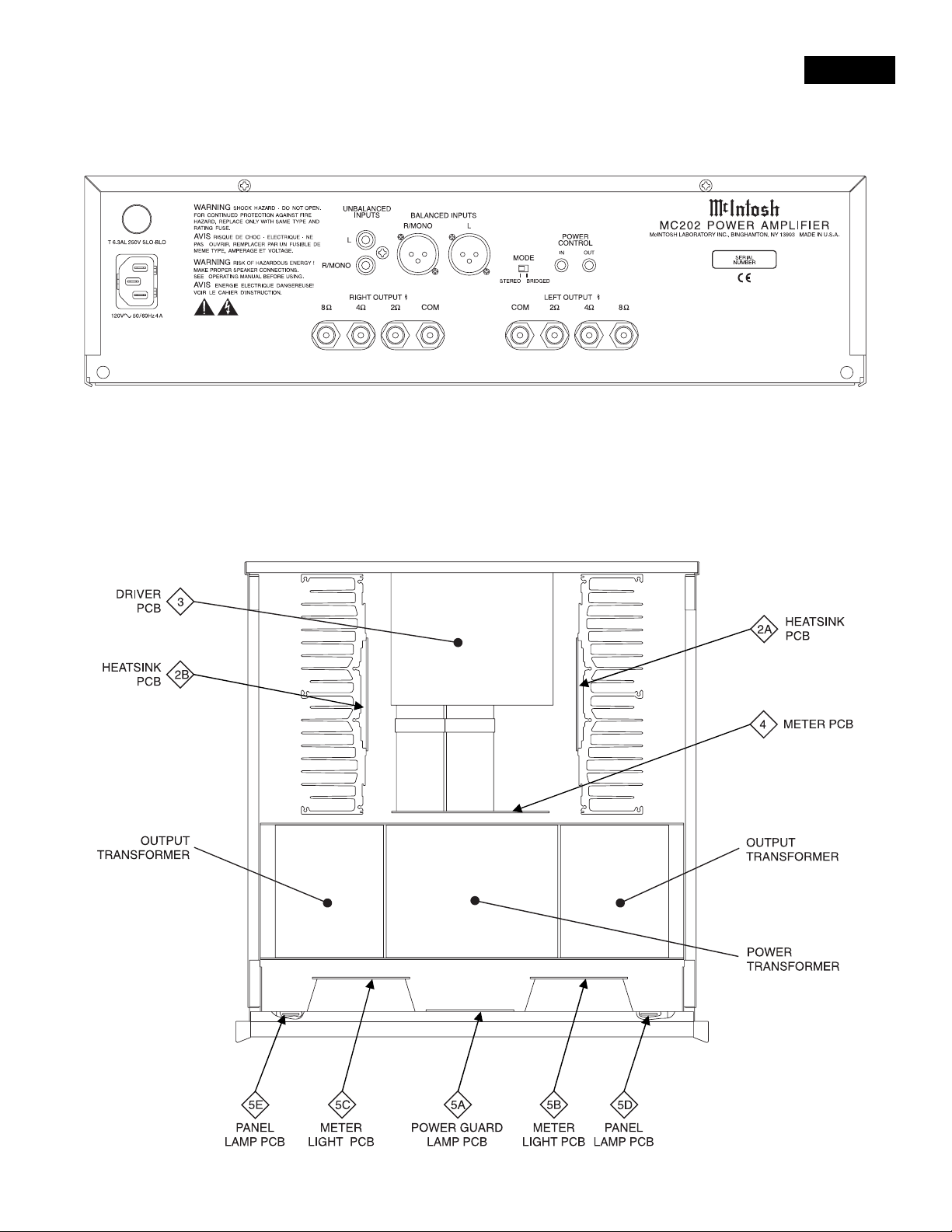
REAR PANEL
SECTION LOCATIONS
MC202
3
Page 4

NOTES
4
Page 5
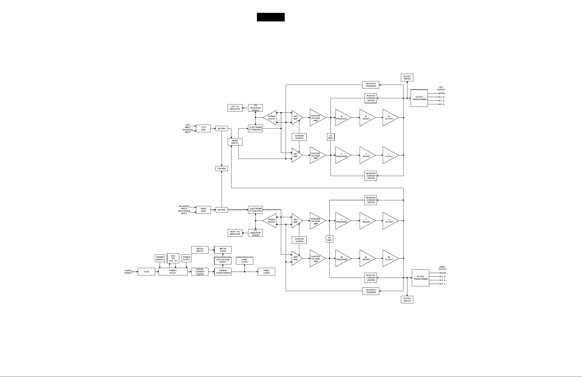
BLOCK DIAGRAM
MC202
5
6
Page 6

INTERCONNECT
7
8
Page 7

MC202
2A
2B
HEATSINK
049346
9
10
Page 8

3
DRIVER
049353
11
12
Page 9

MC202
4
METER
049352
13
14
Page 10

4
METER
049352
5A
POWER GUARD LAMP
049354
15
16
Page 11

MC202
5B
METER LIGHT
049354
5D
PANEL LAMP
049354
5C
METER LIGHT
049354
5E
PANEL LAMP
049354
17
18
Page 12

PARTS LIST
PART NO DESCRIPTION REFERENCE NO
INTERCONNECT
070139 DIODE RECTIFIER D1
089104 FUSE 6.3A 250V SLO BLO F1
124077 METER MT1 MT2
146243 SWITCH S1 S2
049349 POWER TRANSFORMER T1
049350 OUTPUT TRANSFORMER T2
074091 AC TERM BLOCK TB1
049346 HEATSINK PCB
061300 MONO CAP 100PF 100V 5% NPO T&R C7 C8
061304 MONO CAP .01UF 50V 5% X 7R T&R C9 C16
061305 MONO CAP .1UF 50V 5% Z50 T&R C3 C5
064363 CAP POLYPROP 0.15MF 10% 250VDC C10
066446 CAP ELECT 47MF 35V C1 C2
070047 SILICON DIODE 1N4148 T&R D1 D2 D3 D4 D5
070131 DIODE RECTIFIER D6 D7
117213 2-PIN MALE CONNECTOR J4117217 MALE CONN 7 PIN J1
117404 HEADER 2-PIN 0.156 J3117708 FASTON BLADE W/FEET J2
132171 TRANSISTOR NPN Q1
132172 TRANSISTOR SI PNP MPSA55 Q2
132285 TRANSISTOR NPN 25C3334C Q6
132286 TRANSISTOR PNP 2SA32IC Q7
134390 TRIM POT 200 OHM 20% HORIZ AD R13
137093 MET OX 680 5% .5W R2 R9
137094 MET OX 1.8K 5% .5W R6 R11
137095 MET OX 430 5% .5W R7
137096 MET OX 47 5% .5W R12
139177 WIREWOUND RES 0.5 OHM 5W 5% R31 R32 R33 R34 R35 R36
144172 RES MF 221 1% 1/4W R1 R8
144279 THERMISTOR 100 RT1
144378 RES MF 2.21 OHM 1/4W 1% R30
144412 MF RES 15K 1% 1/4W R3 R10
049353 DRIVER PCB
061249 DISC CAP .47UF 50V MONOLITHIC C31 C39
061298 MONO CAP 22PF 200V 5% NPO T&R C115 C116 C118 C120
061299 MONO CAP 47PF 200V 5% NPO T&R C117 C119
061300 MONO CAP 100PF 100V 5% NPO T&R C27 C28 C100 C101 C102
C103
061305 MONO CAP .1UF 50V 5% Z50 T&R C32 C33
064310 CAP MPOLY .0068UF 5% 100/250VDC C105 C106
064363 CAP POLYPROP 0.15MF 10% 250VDC C109 C110
064364 CAP POLYPROP .047MF 10% 250V C107 C108
066446 CAP ELECT 47MF 35V C29 C30
066462 CAP ELECT 1OUF 100VDC C35 C36 C37 C38 C104 C111
C112 C113 C114
066507 CAP ELECT 220UF 25V C22 C44
117215 4-PIN CONNECTOR J3- J4117217 MALE CONN 7 PIN J5- J6117279 11-POS. MALE CONN. J7117436 PJ261G PHON JACK, GOLD J1
117685 XLR RECEPT ACLE FEMALE J2 J8
117759 STEREO 1/8 HEAD PHONE JACK J15 J16
132222 N. CHANNEL FET Q61 Q62
132223 TRANSISTOR NPN MPS4124 2K/REEL Q6 Q35 Q42 Q44 Q45 Q46
Q47 Q49 Q58
132224 TRANSISTOR PNP Q1 Q3 Q19 Q39 Q40 Q43 Q59
Q60
132254 TRANSISTOR NPN Q5 Q34 Q52 Q53 Q55 Q56
132255 TRANSISTOR PNP Q2 Q38 Q48 Q50 Q51 Q54
132285 TRANSISTOR NPN 25C3334C Q17 Q21
132286 TRANSISTOR PNP 2SA32IC Q18 Q22
133260 DUAL OPERATIONAL AMPLIFIER IC1 IC2
137042 FLAMEPROOF RES 47 OHM 5% 1/4W R56 R60
139005 WIRE RES 2 OHMS 10% 5W R177 R179
139119 WIRE RES 4 OHMS 5% 5W R176 R178
144053 RES MF 10K 1% 1/4W R45 R64 R131 R136
144086 RES MF 475 1% 1/4W R164 R171
144089 RES MF 806 1% 1/4W R38 R89 R92 R101
144090 RES MF 1K 1% 1/4W R44 R49
144095 RES MF 3.32K 1% 1/4W R41 R55 R96 R98 R133 R165 R166
144097 RES MF 4.75K 1% 1/4W R46 R47 R135 R162
144104 RES MF 20K 1% 1/4W R132 R148 R156 R161 R172 R175
R182 R183 R184 R185
144106 RES 33.2K 1% 1/4W R153 R163
144108 RES MF 47.5K 1% 1/4W R19 R27 R29 R94
144112 RES 82.5K 1% 1/4W R154 R155 R167 R168
144118 RES MF 267K 1% 1/4W R20 R28 R30 R31 R186
144154 RES MF 12.1K 1% 1/4W R150 R152
144157 RES MF 10 1% 1/4W R67 R68
144172 RES MF 221 1% 1/4W R139 R140 R141 R142 R143 R144
R145 R146
144179 LDR NETWORK VTL5C9 LD1 LD2
144187 RES MF 22.1K 1% 1/4W R157 R169 R170 R173
144196 RES MF 100 1% 1/4W R48 R61 R130
144264 RES MF 10M 1% 1/4W R158 R160
144299 RES MF 2.1K 1% 1/4W R138 R147 R151 R174
144338 RES MF 324 OHM 1% 1/4W R36 R51 R53 R76 R97 R99 R134
R137
144364 RES MF 475K 1% 1/4W R180 R181
144406 METAL FILM RES 187K 1% 1/4W R37 R52 R75 R91
148059 SLIDE SWITCH S1
049352 METER PCB
061305 MONO CAP .1UF 50V 5% Z50 T&R C207 C208 C217 C226 C227
064329 CAP M POLY .22UF 5% 63VDC C244 C245 C246
064337 CAP M POLY 1MF 5% 63VDC C241 C242
066390 CAP ELECT 22UF 100V C243
066445 CAP ELECT 10MF 50V C239 C240 C247
066447 CAP ELECT 100MF 16V C216
066504 CAPACITOR ELECT 25000UF 75V C237 C238
066509 CAP ELECT 3300UF 35V C235 C236
070047 SILICON DIODE 1N4148 T&R D3 D4 D5 D6 D7 D8 D9 D10 D12
D12 D13 D14 D20
070130 ZENER DIODE 8.2V 1/2W D1
070131 DIODE RECTIFIER D15 D16 D17
087052 RELAY 8A R1
089089 FUSE 2A SLO-BLO 5X20 F1
117215 4-PIN CONNECTOR J3117217 MALE CONN:7 PIN J2117279 11-POS. MALE CONN. J1- J9117404 HEADER 2-PIN 0.156 J21- J22117708 FASTON BLADE W/FEET J14 J15 J26- J27 J28 J31 J41 J42 J50
131021 TRIAC 8A 200V Q9
131022 600V TRIAC DRIVER OPTOCOUPLER Q8
132223 TRANSISTOR NPN MPS4124 2K/REEL Q10 Q13 Q14 Q16 Q17 Q18 Q20 Q21
Q22 Q23 Q24
132224 TRANSISTOR PNP Q11
132226 TRANSISTOR P.CHANNEL JUNC.FET Q12
133093 IC REGULATOR +5 VOLT Q3
133192 IC NAND SCHMIT 2-IN X 4 IC4
133260 DUAL OPERATIONAL AMPLIFIER IC2 IC3
134383 TRIM POT 100K OHM 20% R195 R196
139079 WIRE RES 1.5K 10% 5W R198
139218 2.7 OHM 2W 5% WW RESISTOR FP R197
144081 RES MF 68.1K 1% 1/4W R152 R192
144091 RES MF 1.1K 1% 1/4W R2 R3 R167 R172 R191
144106 RES 33.2K 1% 1/4W R165 R166
144120 RES MF 402K 1% 1/4W R199
144128 RES MF 1.5K 1% 1/4W R164
144130 RES MF 10.2K 1% 1/4W R171 R189 R190 R194
144157 RES MF 10 1% 1/4W R138
144187 RES MF 22.1K 1% 1/4W R177 R184
144191 RES MF 1.21K 1% 1/4W R180 R187
144196 RES MF 100 1% 1/4W R175 R181 R186
144265 RES MF 2.21M 1/4W R178 R182
144379 RES METAL FILM 4.75M 1/4W 1% R183 R188
144406 METAL FILM RES 187K 1% 1/4W R4 R5 R179 R185
144418 MF RES 121K 1% 1/4W R170 R173
144421 MF RES 221K 1% 1/4W R193
144422 MF RES 1.5M 1% 1/4W R174 R200
178159 FUSE HOLDER 5X20MM PCB MOUNT F1
049354 POWER GUARD LIGHT\METER LIGHT\PANEL LAMP PCB
058120 LAMP 14V #7373 C1 C2 C3 C4 C5 C6 C9 C10
C11 C12
058133 AMBER LED DS7 DS8
058148 RED LED HIGH EFFICIENCY DS20
117221 MALE CONN 3 POS RT. ANGLE J10117240 4 PIN RT. ANGLE J1- J2- J3- J4- J5-J6- J7- J8- J9117242 11 POS. RT ANGLE J13
117274 CONN. 2 POS. R-ANGLE J11- J12-
19
20
Page 13

EXPLODED VIEW
MC202
21
22
Page 14

EXPLODED VIEW PARTS LIST
Ref
No.
1 016411 GLASS PANEL
2 049320 KNOB ASSEMBLY
3 104017 BLK FELT WASHER
4 018611 5” ENDCAP
5 101042 TS 4-40 X 1/2 SLOT FILLISTER
6 004810 EXTRUSION BRACKET 5”
7 094360 FOAM TAPE 1/2 X 1/2
8 018588 BOTTOM EXTRUSION
9 101172 TCS 6-32 X 1/4 PHIL FLAT U/C
10 018587 TOP EXTRUSION
11 017363 PLEXIGLAS FILTER LIGHT BLUE
12 017711 DISPLAY PLEXIGLAS
13 004804 SUBPANEL
14 112092 REVERSE LOCKING PCB SUPPORT
15 049354 LAMP PCB ASSY
16 022315 FISHP APER SHIELD
17 114072 PLASTIC RIVET
18 101054 TS 6-32 X 1/4 PH PAN TAPTITE BLK
19 112086 NYLON SP ACER
20 102001 KEP NUT 4-40 CADMIUM PLATE
21 004805 SWITCH BRACKET
22 146243 POWER SWITCH
23 124077 METER
24 092341 FIL TER AZURE BLUE
25 092342 FILTER P ALE BLUE
26 017447 PLASTIC LIGHT BOX
27 004809 TOP COVER
28 101078 TS 8-32 X 5/16 PHIL PAN BLK
29 005023 TRAY
30 078003 RUBBER GROMMET
31 106007 SPRING CLIP: LATCH TYPE
32 112038 STL SPACER 4 X 3/8 NICKEL PLT
33 112104 BOARD MOUNT
34 049352 POWER SUPPLY METER PCB ASSY
35 112102 MOUNTING STRAPS
36 049350 OUTPUT TRANSFORMER
37 049349 POWER TRANSFORMER
38 005024 CHASSIS
39 017218 PLASTIC FEET-BLACK
40 104063 FLAT WASHER #10 CLEAR ZINC
41 100159 MS 10-32 X 3/4 PHIL PAN BLK ZINC
42 104067 LK WASH: INTERNAL STAR #10
43 100120 MS 10-32 X 1/4 PHIL PAN ZINC
44 101176 TCS 6-32 X 1/2 PH PAN BLK TYPE F
45 074091 AC TERMINAL BLOCK
46 104001 FLAT STEEL WASHER #4 X 9/32 X .025
47 104004 LK WASHER 5 X .255 INT STAR
48 102022 MN 4-40 3/16 X 3/16
49 084135 THERMAL PAD
50 070139 RECTIFIER BRIDGE
Part
No.
Description
51 102003 MACH NUT 6-32 W/LOCK
52 112103 HEX SPACER 6-32 X 2.375
53 049353 DRIVER PCB ASSY
54 104005 STEEL WASHER: FLAT 6 X 3/8 X .032
55 100255 SEMS 6-32 X 3/8 PHIL PAN INTERNAL
56 018617 AMPLIFIER HEATSINK
57 017160 MOUNTING TAB W/ .140 DIA MTG
58 084187 ISOSTRATE
59 112087 PCB SPACER 1/4”
60 049346 HEATSINK PCB ASSY
61 101059 SM 6 X 5/8 PHIL PAN TYPE A
62 114118 TRANSISTOR CLIP 218
63 114119 TRANSISTOR CLIP 214
64 110009 NUT M5 X 0.8 BRASS WITH GOLD PLATE
65 104130 LK #10 SPLIT PHOS/BRONZE
66 104148 FLAT WASHER BRASS
67 084189 DUAL BINDING POST RED
68 084124 DUAL BINDING POST
69 102020 MACH NUT 6-32 SELF-LOCK
70 178161 FUSE HOLDER 5 X 20mm IEC
71 104016 LK WASH: 1/2 X .630 X .022 INT STAR
72 004800 OUTPUT PLATE
73 005022 REAR P ANEL
74 117487 AC LINE RECEPTACLE
75 101197 HI/LO 4-24 X 3/8 PHIL ROUND BLACK
76 101114 SM 4-24 X 1/2 PHIL PAN TYPE A
77 017706 TERMINAL COVER
78 094332 DOUBLE COATED MTG TAPE 1/8” THICK
79 078017 GROMMET 3/4 X 9/16
80 104142 LOCKWASHER 2.5mm INT STAR ZINC
23
24
Page 15

REPACKING INSTRUCTIONS
25
Page 16

POWER AMPLIFIER
SERVICE MANUAL
The continuous improvement of it’s products is the policy of McIntosh Laboratory Incorporated, who reserve the right to improve design without notice.
Because of the constant upgrading of McIntosh products’ circuitry and components, the Company cannot insure, and does not warrant, the accuracy of the
within schematic material, which is intended for information only.
McINTOSH LABORATORY, INC., 2 CHAMBERS STREET, BINGHAMTON, NEW YORK 13903 Printed in U.S.A. Part Number 040722
 Loading...