

Page 1

MC150
POWER
AMPLIFIER
Page 2

Page 3
MC150
POWER
AMPLIFIER
Page 4
IMPORTANT
SAFETY
INSTRUCTIONS
THESE
INSTRUCTIONS
ARE TO PROTECT
YOU AND THE
MclNTOSH
INSTRUMENT.
BE SURE TO
FAMILARIZE
YOURSELF
WITH THEM
1. Read all instructions - Read the safety and and operating instructions before operating the instrument.
2. Retain Instructions - Retain the safety and operating instructions for future reference.
3. Heed warnings - Adhere to warnings and operating instructions.
4. Follow Instructions - Follow all operating and use instructions.
WARNING: TO REDUCE RISK OF FIRE OR ELECTRICAL SHOCK, DO NOT EXPOSE
THIS INSTRUMENT TO RAIN OR MOISTURE.
5. Power Sources - Connect the power supply only to the type described in the operating instructions or
as marked on the unit
6. Power Cord Protection - Route power supply cords so that they are not likely to be walked on or pinched
by items placed upon or against them, paying particular attention to cords at plugs, convenience
receptacles, and the point where they exit from the instrument.
7. Ventilation - Locate the instrument for proper ventilation. For example, the instrument should not be
placed on a bed, sofa, rug, or similar surface that may block ventilation openings; or, placed in a built-in
installation, such as a bookcase or cabinet, that may impede the flow of air through the ventilation
openings.
8. Heat - Locate the instrument away from heat sources such as radiators, heat registers, stoves, or other
appliance (including amplifiers) that produce heat.
9. Wall or Cabinet Mounting - Mount the instrument in a wall or cabinet only as described in the owner's
manual.
10. Water and Moisture - Do not use the instrument near water - for example, near a bathtub, washbowl,
kitchen sink, laundry tub, in a wet basement or near a swimming pool, etc.
11. Cleaning - Clean the instrument by dusting with a dry cloth. Clean the panel with a cloth moistened with
a window cleaner.
12. Object and Liquid Entry - Do not permit objects to fall and liquids to spill into the instrument through
enclosure openings.
13. Nonuse Periods - Unplug the power cord from the AC power outlet when left unused for a long period
of time.
14. Damage Requiring Service - Service must be performed by qualified service personnel when:
A. The power supply cord or the plug has been damaged; or
B. Objects have fallen, or liquid has been spilled into the instrument; or
C. The instrument has been exposed to rain; or
D. The instrument does not appear to operate normally or exhibits a marked change in performance or
E. The instrument has been dropped, or the enclosure damaged.
15. Servicing - Do not attempt to service beyond that described in the operating instructions. All other service
should be referred to qualified service personnel.
16. Grounding or Polarization - Do not defeat the inherent design features of the polarized plug. Nonpolarized line cord adapters will defeat the safety provided by the polarized AC plug.
17. CA U TION: TO PREVENT ELECTRICAL SHOCK DO NOT USE THIS (POLARIZED)
PLUG WITH AN EXTENSION CORD, RECEPTACLE OR OTHER OUTLET UNLESS THE
BLADES CAN BE FULLY INSERTED TO PREVENT BLADE EXPOSURE.
ATTENTION: POUR PEVENIR LES CHOCS ELECRIQUES PAS UTILISER CETTE
FICHE POLARISEE AVEC UN PROLONGATEUR, UNE PRISE DE COURANT OU UNE
AUTRE SORTIE DE COURANT, SAUF SI LES LAMES PEUVENT ETRE INSEREES A
FOND SANS EN LAISSER AUCUNE PARTIE A DECOUVERT.
The lightning flash with arrowhead, within an equilateral triangle, is intended to alert the user
to the presence of uninsulated "dangerous voltage" within the product's enclosure that may be
of sufficient magnitude to constitute a risk of electric shock to persons.
CAUTION: TO PREVENT THE RISK OF ELECTRIC SHOCK, DO
NOT REMOVE COVER (OR BACK). NO USER-SERVICEABLE PARTS
INSIDE. REFER SERVICING TO QUALIFIED PERSONNEL.
The exclamation point within an equilateral triangle is intended to alert the user to the presence
of important operating and maintenance (servicing) instructions in the literature accompanying
the appliance.
Copyright 1995 © by
Mclntosh Laboratory, Inc.
WARNING: THIS UNIT IS CAPABLE OF PRODUCING HIGH SOUND
PRESSURE LEVELS. CONTINUED EXPOSURE TO HIGH SOUND
PRESSURE LEVELS CAN CAUSE PERMANENT HEARING IMPAIRMENT
OR LOSS. USER CAUTION IS ADVISED AND EAR PROTECTION IS
RECOMMENDED WHEN PLAYING AT HIGH VOLUMES.
2
Page 5

Your decision to own this piece of Mclntosh Stereo Equipment ranks you at the very top
among discriminating music listeners. You now have "The Best". The Mclntosh dedication to
"Quality", is assurance that you will receive thousands of hours of musical enjoyment from this
unit.
Please take a short time to read the information in this manual. We want you to be as
familiar as possible with all the features and functions of your new piece of Mclntosh. This will
ensure that you receive all the performance benefits this instrument can offer you, and that
it will become a highly valued part of your home music system.
The serial number, purchase date, and Mclntosh Laboratory Service Contract number are
important to you for possible insurance claim or future service. Record this information here.
Serial Number Purchase Date
Service Contract Number
Upon application, Mclntosh Laboratory provides a Service Contract to the original
purchaser. Your Mclntosh Authorized Service Agency can expedite repairs when you provide
them with the Service Contract.
THANK
YOU
SERVICE CONTRACT 5
TABLE OF
INTRODUCTION 5
INSTALLATION 5, 6
FRONT PANEL 6, 7
REAR PANEL 7, 8, 9, 10
CONNECTIONS 11
TECHNICAL DESCRIPTION 12, 13, 14
SPECIFICATIONS 15
CUSTOM INSTALLATION DIAGRAM 16
RECOMMENDED VENTILATION CUTOUT IN MOUNTING SHELF 16
CONTENTS
3
Page 6

MclNTOSH
THREE YEAR
SERVICE
CONTRACT
TAKE ADVANTAGE OF 3 YEARS OF CONTRACT SERVICE . . .
FILL IN THE APPLICATION NOW.
Your MC150 Power Amplifier will give you many years of satisfactory performance. If you
have any questions, please contact,
Mclntosh Laboratory, Inc.
2 Chambers Street
Binghamton, NY 13903-2699
Phone: 607-723-3512
An application tor A THREE YEAR SERVICE CONTRACT is included with this manual.
The terms of the contract are:
1. If the instrument covered by this contract becomes defective. Mclntosh will provide all parts,
materials, and labor needed to return the measured performance of the instrument to the
original performance limits free of any charge. The service contract does not cover any
shipping costs to and from the authorized service agency or the factory.
2. Any Mclntosh authorized service agency will repair all Mclntosh instruments at normal
service rates. To receive the free service under the terms of the service contract, the service contract certificate must accompany the instrument when taken to the service agency.
3. Always have service done by a Mclntosh authorized service agency. If the instrument is
modified or damaged as a result of unauthorized repair the service contract wilt be cancelled. Damage by improper use or mishandling is not covered by the service contract.
4. The service contract is issued to you as the original purchaser. To protect you from
misrepresentation this contract cannot be transferred to a second owner.
5. Units in operation outside the United States and Canada are not covered by the Mclntosh
Factory Service Contract, irrespective of the place of purchase. Nor are units acquired
outside the USA and Canada, the purchasers of which should consult with their dealer
to ascertain what, if any, service contract or warranty may be available locally.
4
Page 7

The electrical and mechanical design of the MC150 power amplifier is the result of the
many years of engineering and manufacturing experience of the design staff at Mclntosh.
This "Know How", along with the meticulous attention to design and production details, makes
the MC150 one of the finest amplifiers ever produced by Mclntosh Laboratory.
The use of 6 complimentary connected output transistors per channel, allows not only full
power output into normal loads, but extra high current output to drive uneven speaker loads.
Some speaker designs have impedance characteristics that may dip to as low as 1 or 2
ohms at certain frequencies. It is possible for the MC150 to deliver as much as 50 amperes
peak current into these lower impedance loads.
The MC150 provides this extra current output with complete reliability due to the use of
Mclntosh Sentry Monitor protection circuits. Some power amplifier manufacturers have
claimed that their products do not use protection circuits since they compromise perfor-
mance. The real genius of Mclntosh engineering design has recognized these potential
problems and completely eliminated them. Properly designed protection circuits assure you
an amplifier that will operate under all types of user conditions with maximum reliability and
freedom from possible speaker or amplifier damage. The benefits of these designs mean you
own an amplifier that will continue to operate safely for many years.
The MC150 output is so distortion free, it is difficult to measure with conventional instru-
ments. The performance limit is 0.005% maximum distortion, yet it is typical for an amplifier
to measure less than 0.002% at mid frequencies.
The power output watt meters on the MC150 are peak responding, and indicate the TRUE
power output of the amplifier. The MC150 meter circuits are constantly measuring both
voltage and current delivered into the speaker loads. A speaker may have a different load
impedance at different frequencies, resulting in a change of output current. The MC150
meters properly react to this condition and indicate Real Output power.
Other desirable features are included such as high current gold plated output terminals.
As in all Mclntosh power amplifiers, the famous patented Mclntosh POWER GUARD circuit is included. You never have to be concerned with amplifier overdrive when playing wide
dynamic range program sources such as compact discs.
Refer to the technical description for a full account of all the outstanding circuit and per-
formance features of this superb power amplifier.
INTRODUCTION
The MC150 can be placed upright on a table or shelf, standing on its four plastic feet.
It can also be installed in the optional Mclntosh L72 equipment cabinet. Follow the
mounting instructions enclosed with the L72 cabinet.
The MC150 can be custom Installed in a cabinet of your choice. The mounting panel
cutout, mounting shelf ventilation cutout and amplifier dimensions are Included on a
page further back in this manual.
it is essential to cut out a ventilation hole in the mounting shelf according to the
dimensions in the drawing.
Always provide adequate ventilation for the amplifier. The trouble free life of any electronic
instrument is greatly extended by providing sufficient ventilation for proper cooling. In a
INSTALLATION
5
Page 8

INSTALLATION
system stack, the power amplifier should always be at the top. If all the components are
installed in a single cabinet, a quiet running ventilation fan can be a definite asset in
maintaining all the system components at their coolest possible operating temperatures.
Allow at least 1-1/2 inches (3.8cm) above the heat sink area to allow the free flow of air.
Cut out a ventilation hole in the mounting shelf corresponding to the dimensions in the draw-
ing. The recommended minimum depth for mounting, including clearance for connectors is
16-1/2 inches (41.9cm). Allow 1-1/8 inches (2.9cm) in front of the mounting panel for knob
clearance.
FRONT
PANEL
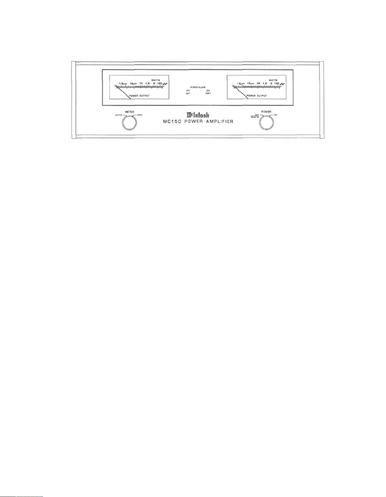
POWER OUTPUT METERS
The MC150 power output meters respond 95% full scale to a single cycle of a 2000Hz
tone. Both voltage and current are electronically measured and fed to a special circuit that
accelerates the pointer movement in the upward direction. When the meter pointer reaches
its peak, it is time stretched to pause just long enough to be read, and then drops.
The upper scale on the meters is calibrated in average watts power, and the lower scale
in decibels. The meter calibration marks reading from right to left, starting at the 150 watt
indication, are as follows.
150
60
30
15
6
3
1.5
0.6
0.3
watts, (+3dB), and 600 watts, (+6dB). The power amplifier cannot produce a continuous 600
watts of power, but can produce well beyond 150 watts on program peaks, especially into
lower impedance speaker loads.
METER WATTS/HOLD
produced by the amplifier and read to an accuracy of at least 95% of the power output of
either amplifier channel.
a sequence of peaks. The meter is electronically held to this power level until another higher
power peak passes through the amplifier. The meter pointer will then rise to the newer higher
indication. If no further power peaks are reached, the meter pointer will very slowly return to
its rest position or lower power level. The decay rate is approximately 6 dB per minute.
Watts Indicated
Watts Indicated
Watts Indicated
Two additional calibration marks above 150 watts are on the meters. The first is 300
In the METER WATTS position, the meters respond to all the musical information being
In the METER HOLD position, the meter pointer is locked to the highest power peak in
0.15 Watts Indicated
0.06
0.03
15 Milliwatts Indicated
6
3
1.5 Milliwatts Indicated
0.6
0.3
6
Page 9

POWER GUARD
The patented Mclntosh POWER GUARD circuit prevents the MC150 from ever being
driven into clipping. This protects you from distortion and possible speaker damage. The
POWER GUARD LED near each meter will light whenever POWER GUARD is activated on
either channel, and indicates that you are being protected.
POWER/OFF-REMOTE/ ON
Turn on the MC150 power by turning the front panel POWER switch to ON. You can also
turn the MC150 power on with a Power Control signal from an accessory Mclntosh component or Control Center that includes a Power Control Out. Plug the MC150 power cable
into a wall outlet. Connect a data cable from the accessory component Power Control OUT
to the MC150 Power Control IN and set the POWER switch to OFF-REMOTE. When the
accessory component turns on, it will send a control signal to the amplifier causing it to turn
on.
FRONT
PANEL
HOW TO CONNECT INPUTS
CONNECTING CABLES
Use shielded cables to connect the signal from the preamplifier or other signal source
to the power amplifier. To minimize the possibility of hum, the cables should be located away
from speaker connecting cables and AC power cords.
Use good quality cables. Your dealer can advise you on the type and lengths of cables
that will best suit your installation.
STEREO OPERATION (UNBALANCED INPUTS)
Connect two shielded cables using RCA connectors from the left and right unbalanced out-
puts of a Preamplifier or Control Center t o the MC150 LEFT and RIGHT/MONO unbalanced inputs.
STEREO OPERATION (BALANCED INPUTS)
Modern technology has made it possible to build preamplifiers and power amplifiers with
the high signal to noise ratio necessary to reproduce the sound quality present on compact
discs or any other wide dynamic range signal source.
It is possible for conventional interconnecting cables to pick up electrical interference
from other equipment, AC cables or electrical appliances. Using the balanced inputs provides an additional 40dB more protection against noise pickup.
Use 2 conductor shielded cables with XLR type connectors to connect between the preamplifier and the power amplifier. The maximum effect of balanced cables is realized when
both the preamplifier and power amplifier have similar XLR balanced connectors.
Connect the left balanced output cable from a preamplifier to the LEFT BALANCED
INPUT on the power amplifier. Connect the right output to the RIGHT BALANCED INPUT.
Pin configuration for the XLR INPUT connectors on the MC150.
PIN 1: Shield or ground.
PIN 2: + input.
PIN 3: - input.
In stereo Installations where the amplifier and preamplifier are close to each other and
require interconnecting cables of six feet or less, using quality unbalanced connecting cables
is usually equally satisfactory. If the units are farther apart and require longer Interconnecting
cables, using balanced cables will give extra protection from noise or Interference.
REAR
PANEL
7
Page 10

REAR
PANEL
MONOPHONIC BRIDGED OR PARALLEL
A rear panel MODE switch allows the amplifier to be used in normal STEREO, MONO
(BRIDGED) or MONO (PARALLEL). When switched to either MONO (BRIDGED), or MONO
(PARALLEL) operation, the RIGHT BALANCED and UNBALANCED inputs are the only ones
used for the mono input signal. The LEFT inputs are automatically disconnected.
Connect the appropriate cable from a preamplifier or other mono source to the
appropriate RIGHT UNBALANCED or BALANCED amplifier input.
HOW TO CONNECT OUTPUTS
The Mclntosh output circuit, superior in its performance, demands a superior method of
coupling the amplifier output to the loudspeaker load. The MC150 incorporates Mclntosh
designed and manufactured Autoformers to insure peak performance and protection, as well
as outstanding compatibility between amplifier and speakers.
The MC150 Output Autoformers have 3 different output impedance taps for optimum
matching to the particular speaker or combination of speakers being used. Use the following
table to determine which tap should be used. It may be desirable to consult your dealer, or
the manufacturer of your speaker for the best impedance tap to use.
SPEAKER IMPEDANCE IN OHMS AMPLIFIER OUTPUT CONNECTIONS
2 to 4 Common and 2 ohm output
4 to 8 Common and 4 ohm outputs
8 and up Common and 8 ohm outputs
Use high quality speaker cables. The total resistance of the cables must be as low as
possible, so larger diameter, (lower gauge number), cables are most desirable. The longer
the speaker cable is, the lower the gauge number must be to keep resistance low. Consult
your dealer for the best cables for your particular installation.
RECOMMENDATIONS FOR SPEAKER CABLE LENGTHS AND GAUGE (SIZE)
These speaker cable lengths represent a resistance equal to approximately 5% of the
speaker impedance. The cable sizes are the minimum that should be used. If there is a
choice, the larger diameter cables, (smaller gauge number), should be used.
4 OHM SPEAKERS
FEET
100
STEREOPHONIC OPERATION
COM terminal. Connect a cable from the left speaker hot terminal to the amplifier LEFT
METERS
15
25
40
60
Set the rear panel MODE switch to STEREO
Connect a cable from the left speaker common terminal to the amplifier LEFT OUTPUT
4.6
7.6
12.2
18.3
30.5
8 OHM SPEAKERS
FEET
30
50
80
120
200
METERS
9.1
15.2
24.4
36.6
61.0
CABLE
GAUGE
18
16
14
12
10
8
Page 11

OUTPUT (impedance tap desired) terminal. Two ohms, 4 ohms and 8 ohms are provided.
Connect the right speaker in an identical manner to the amplifier RIGHT OUTPUT
terminals of the correct impedance for your speakers.
If the actual load impedance of a speaker is lower than the specified impedance, particularly at different parts of the frequency range, it will cause no problems. The high current
output capacity of the MC150 will produce the extra current necessary to properly drive the
speaker under these conditions.
If the impedance of the speaker is higher then the 8 ohm tap, no change in performance
quality will occur. The available power output will simply be slightly less.
The COMMON and HOT terminals of both speakers must be connected in an identical
manner to the proper amplifier output terminals. This is essential for keeping the speakers
operating IN PHASE. This means that the speaker driver surfaces move back and forward
the same in each speaker. Almost all speakers have their hot and common terminals color
coded, with red as hot.
MONOPHONIC BRIDGED OPERATION
Set the rear panel MODE switch to MONO BRIDGED and use only a RIGHT/MONO
balanced or unbalanced Input.
The MC150 can be used as a single channel monophonic power amplifier in bridged
configuration. The two amplifier channel outputs add together in series when used in MONO
(BRIDGED). The MODE switch connects the right channel inputs to both power amplifiers, with
the phase of the left channel inverted to get bridged operation. The speaker connections, both
common and hot, should be connected only to the left and right amplifier output impedance taps
as shown. The COMmon amplifier output connections are not used in MONO (BRIDGED)
configuration. For example, the two 8 ohm outputs will add to become 16 ohms, or the two 4 ohm
outputs will add to become 8 ohms.
To maintain the mono output of the amplifier in phase with the input signal in MONO
(BRIDGED) operation, connect the Hot speaker terminal to the RIGHT channel impedance tap
and the Common speaker terminal to the LEFT channel impedance tap.
REAR
PANEL
SPEAKER IMPEDANCE IN OHMS
AMPLIFIER OUTPUT CONNECTIONS
4 to 8 LEFT 2 and RIGHT 2 (4 ohms total)
8 to 16 LEFT 4 and RIGHT 4 (8 ohms total)
16 and up LEFT 8 and RIGHT 8 (16 ohms total)
MONOPHONIC PARALLEL OPERATION
Set the rear panel MODE switch to MONO (PARALLEL) and use only a RIGHT/
MONO balanced or unbalanced Input.
The MC150 also can be used as a single channel monophonic power amplifier in parallel
configuration. The amplifier output taps are now connected in parallel and the impedances will
be exactly half what is stated at the terminals.
Connect a cable from the speaker common terminal to the either the LEFT OUTPUT COM
terminal or the RIGHT OUTPUT COM terminal. (These terminals are wired together inside the
amplifier). Connect the cable from the hot speaker terminal to the impedance output desired on
either channel. Also wire across to the other channel identical impedance tap. In each case, the
chosen outputs of each channel must be wired together.
9
Page 12

REAR
PANEL
SPEAKER IMPEDANCE AMPLIFIER
IN OHMS OUTPUTS
1 to 2 LEFT COM + RIGHT COM and LEFT 2 + RIGHT 2, (1 ohm)
2 to 4 LEFT COM + RIGHT COM and LEFT 4 + RIGHT 4, (2 ohms)
4 and UP LEFT COM + RIGHT COM and LEFT 8 + RIGHT 8, (4 ohms)
MAKE SURE THE REAR PANEL MODE SWITCH IS SET TO MONO (PARALLEL) AND
USE ONLY A RIGHT INPUT. ALWAYS PLACE THE MODE SWITCH IN THE CORRECT
POSITION FOR THE MODE OF OPERATION BEING USED.
The MC150 can be used to feed a constant voltage line, often used in background music
applications. For a 25 volt line, use the 4 ohm outputs on the amplifier.
Because the crosstalk between channels on the MC150 is almost non existent, each
channel can be used as a separate monophonic amplifier. An example would be one
channel feeding background music to a given area, and the other channel used for paging
in a different area.
LEFT LEVEL
Use the LEFT LEVEL control to adjust the output in the left channel to the desired listening level.
RIGHT LEVEL (MONO)
Use the RIGHT LEVEL control to adjust the output in the right channel to the desired
listening level,
When the amplifier is connected for either bridged or parallel monophonic operation, the
RIGHT LEVEL control is used to control the combined monophonic level of both channels.
The 2.5V (detent) settings are recommended for best operation with a Mclntosh
Control Center or Preamplifier.
POWER CONTROL, IN/OUT
The MC150 AC power can be turned on and off by a control signal fed to the POWER
CONTROL IN connector from the POWER CONTROL OUT connector on compatible Mclntosh
products. The MC150 POWER CONTROL OUT jack will feed the same power control signal
out, delayed 0.2 seconds, to turn on and off another accessory component with a compatible
Power Control input.
The MC150 POWER switch must be in the OFF/REMOTE setting for the power control
signals to turn the MC150 On and Off.
The POWER CONTROL connectors are standard 1/8 inch mini phone plugs. Only the tip
(+) and sleeve (-) are used for connecting the plug to a single conductor shielded cable.
HOW TO CONNECT AC POWER
The MC150 is designed to operate on 120 volts 50/60 Hz. Plug the AC power cord either
directly into a wall outlet or in the amplifier AC receptacle on the back of a preamplifier. Make
certain that the AC power outlet used has at least 7 amperes capacity available.
The MC150 can draw up to 6.25 amperes of current from the AC power line when both
channels are producing rated power output. The amplifier uses only 0.5 amperes of current
when idling at no output.
FUSE
A 6.25 ampere fuse protects the MC150 circuits.
10
Page 13

CONNECTIONS
11
Page 14

TECHNICAL
DESCRIPTION
The MC150 is a stereo power amplifier designed to operate with loudspeakers having
a nominal impedance of 2, 4 or 8 ohms.
It features a new circuit design that holds harmonic distortion far below the amplifier's
remarkably low noise floor. Only by using special spectrum analysis measuring techniques
is the distortion measurable at all.
DESIGN PHILOSOPHY
The secret to this performance will sound very simple, but it is more difficult to carry out
than it may seem. The principle used in the design of the MC150 was to arrange every stage
of voltage or current amplifications to be as linear as possible.
This linear operation is accomplished by using several different techniques.
1. Each transistor is selected to have nearly constant current gain (Beta) over the entire
range of currents at which the transistor must operate.
2. The load impedance presented to each amplification stage is made to be as uniform a
possible for all signal levels.
3. The input impedance of stages in increased and linearized where possible by using
emitter degeneration.
4. Resistors and capacitors in the signal path at carefully selected to have exceedingly low
voltage coefficients (low change of resistance or reactance with applied voltage).
Precision metal film resistors and low dielectric absorption film capacitors are used in
all critical circuit locations.
5. Output transistors have matched uniform current gain, high current gain-bandwidth
product, low output capacitance, and large active-region safe operating area. These
characteristics and the automatic tracking bias system eliminates crossover distortion. The
distortion graphs show clearly that distortion does not increase at low power output levels.
OVER 58 JOULES OF ENERGY STORAGE
Huge main filter capacitors are used to guarantee an excellent signal to noise ration and
the energy storage necessary for the wide dynamic range that "Digital Audio" demands.
ILLUMINATED PEAK RESPONDING OUTPUT WATTMETERS
The MC150 includes REAL OUTPUT WATTMETERS. The power output in WATTS of any
amplifier is determined by multiplying the output voltage (E) by the output current (I), EI=W.
Output meters on other amplifiers are only voltmeters. Output current is not considered. Calibration is in watts and is based on the false premise that all speakers have a fixed impedance regardless of frequency. In fact, the impedance of many poor speaker designs varies
by as much as 4 to 1. For a specific output voltage, the current varies inversely to the speaker impedance. So if the speaker impedance is lower, the output current and power are
higher. Since Mclntosh cannot control other manufacturers speakers, we decided to provide
extra output current to drive them. Therefore, the meter circuit in the MC150 electronically
measures both voltage and current, multiplies them and displays the REAL OUTPUT POWER
IN WATTS.
Another important feature of these output wattmeters is their ability to respond 95% full
scale to a single cycle tone burst at 2kHz. After voltage and current are measured and
multiplied, the product is fed to a special circuit that accelerates the meter pointer in the
upward direction. When it reaches its peak, it pauses only long enough for the human eye
to perceive its position, then returns to 0. Response is almost 10 times faster than a professional VU meter.
12
Page 15

A front panel switch is provided to change the meters to the WATTS HOLD mode of
operation, fast upward movement of the pointer, but greatly increased HOLD time at the peak
of its travel. The highest power output of the source material is thus recorded.
OUTPUT AUTOFORMERS
The unequalled expertise of Mclntosh in the design and manufacture of output autoformers is legendary in the Hi Fi industry. In the MC150, they provide proper matching for
2, 4 and 8 ohm loads. They protect your speakers from damage in the event of an output
transistor failure, provide low distortion power transfer at frequencies well beyond human
hearing and deliver peak output currents in excess of 53 amperes.
PROTECTION CIRCUITS
Some manufactures of power amplifiers advertised that their products do not require or
use protection circuits and that such circuits compromise performance. Mclntosh Laboratory
agrees that diligent measures are required to allow unrestricted performance, but we also
insist that protection circuits are desirable and necessary to prevent amplifier or loudspeaker
damage due to abnormal circumstance and that they actually enhance performance. The
MC150 incorporates seven protection circuits to enhance its performance, assure its reliability
and to protect loudspeakers.
POWER GUARD
Power Guard, a unique feature of Mclntosh amplifiers, assures that each channel of the
MC150 will deliver full power free of clipping distortion. Clipping is caused when an amplifier
is asked to produce more power output than its design is capable of delivering with low dis-
tortion. Amplifiers that are overdriven may deliver large quantities of power when they are
clipping, but they may have more than 40% harmonic distortion. In this mode, the sound is
grossly distorted and the extra energy content of the clipped signal will damage most loudspeakers, The Mclntosh Power Guard circuit protects your ears and your speakers from this
kind of damage.
The Power Guard circuit consists of a waveform comparator which monitors the wave
shape of the amplifier input and output signals. Normally, there is no disparity between these
signals and the comparator produces no output. When the amplifier is driven beyond its
maximum power capacity, a difference will develop. If the disparity exceeds 0.3% (equivalent
to 0.3% total harmonic distortion), the comparator output causes the amber Power Guard
indicator to light. If there is a further increase in the disparity, the comparator output controls
and electronic attenuator at the amplifier input to reduce the amplifier gain, thus holding the
amplifier output to a low distortion value. Overdrive by 14dB is possible before the output
distortion exceeds 2%.
SENTRY MONITOR
TECHNICAL
DESCRIPTION
All power transistors have limits for the maximum amount of power they can handle. The
MC150 output transistors and power supply have been designed to allow very high current
flow into properly matched load impedances. If, however, a short circuit or very low value of
load impedance is applied tot he output of the MC150, destructive current levels could be
reached if it was not controlled by the Sentry Monitor circuit. This circuit senses the dynamic
operating time, voltage, and current of the amplifier output sage and controls the current flow
confining it to nondestructive limits. Sentry Monitor does not limit the power out-put available
from the amplifier.
13
Page 16

TECHNICAL
DESCRIPTION
THERMAL CONTROL
All power transistors have limits for the maximum amount of heat they can tolerate. The
MC150 uses a highly efficient amplifying circuit which produces relatively little heat for the
output power produced. The amplifier has 4 oversize heatsinks to dissipate transistor
generated heat, natural convection air flow is sufficient for cool operation. Should the cooling
air be blocked or should the amplifier operating temperature become too high, thermal cutouts within the amplifier will turn off the power to the amplifier. When the amplifier has cooled,
it will automatically turn on again.
TURN-ON DELAY
The MC150 has a turn-on delay circuit that delays amplifier operation for about 2
seconds after power turn-on. This prevents pops or thumps generated in other equipment
from causing annoying noises or damaging your loudspeakers.
DIRECT CURRENT FAILURE PROTECTION
The autotransformer protects speakers from damage in the event of amplifier failure.
Should a direct current component appear in the output, it is shunted by the autotransformer
and DC cannot damage the speaker.
POWER LINE INRUSH PROTECTION
Turn-on inrush current is cushioned by thermistors in the power transformer primary
circuit. A soft start is achieved that eliminates component stress during turn-on.
CIRCUIT OPERATION
The audio input passes through the gain control to a preamplifier. The output amplifier
is driven by the preamplifier.
The power output amplifier uses two stages of voltage amplifications followed by three
stages of current amplifications. All stages are complementary balanced, Even number harmonics are cancelled by the balanced circuits. This means that the amplifying stages have
less total harmonic distortion and less negative feedback is required to achieve ultra low distortion.
The signal is fed to one input of the balanced differential stage. Feedback from the amp-
lifier output is applied to the other input. The differential amplifiers drive a balanced cascode
connected voltage amplifier stage. Current mirrors are also used to improve band width and
linearity.
The cascode voltage amplifier output feeds complementary Darlington connected driver
transistors. These supply the signal to 6 complementary connected output transistors per
channel. Ancillary components for Power Guard, Sentry Monitor, Power Output Meters and
other protection circuits interconnect with the amplifier circuits. The power supply uses a
massive power transformer, full wave bridge rectifiers. Large filter capacitors having 58 joules
of energy storage. Four large heatsinks provide cooling for the 12 output power transistors.
The mechanical and electrical design of the MC150 is the result of the many years of
engineering and manufacturing experience held by the staff at Mclntosh This "Know How",
the meticulous attention to design and production details, makes the MC150 one of the finest
amplifiers ever produced by Mclntosh Laboratory, Inc.
14
Page 17

POWER OUTPUT
STEREO
150 watts minimum sine wave continuous average power output, per channel,
both channels operating into 2 ohms, 4
ohms or 8 ohms load impedance.
OUTPUT LOAD IMPEDANCE
2 ohms, 4 ohms and 8 ohms; separate
terminals are provided for each output.
RATED POWER BAND
20Hz to 20,000Hz
TOTAL HARMONIC DISTORTION
0.005% maximum harmonic distortion at
any power level from 250 milliwatts to 150
watts per channel from 20Hz to 20,000Hz,
both channels operating.
INTERMODULATION DISTORTION
0.005% maximum harmonic if instan-
taneous peak power output is 300 watts or
less per channel with both channels operating for any combination of frequencies,
20Hz to 20,000Hz.
FREQUENCY RESPONSE
(AT ONE WATT OUTPUT)
20Hz to 20,000Hz + 0, -0.25dB.
10Hz to 100,000Hz +0, -3dB.
NOISE AND HUM (A-weighted)
110dB below rated output.
IHF DYNAMIC HEADROOM
1.8dB
RATINGS
DAMPING FACTOR
Greater than 40.
INPUT IMPEDANCE
20,000 ohms.
INPUT SENSITIVITY
1.4 volt, level control provides for higher
input voltages; 2.5 volt position at detent.
POWER GUARD
Clipping is prevented and THD does
not exceed 2% with up to 14dB overdrive at
1kHz.
POWER REQUIREMENT
120 volts, 50/60Hz, 0.5 to 6.5 amperes
SEMICONDUCTOR COMPLEMENT
62 silicon diodes.
2 light emitting diodes.
72 Bipolar transistors
7 Integrated circuits.
DIMENSIONS
Front panel measures 17-1/2" (44.5cm)
wide, by 5-3/8" (13.7cm) high. Depth behind
mounting panel including clearance for
connectors, 19-3/4' (50.2cm). Knob clearance
required in front of mounting panel, 1-1/8"
(2.9cm).
WEIGHT
59 lbs. (26.8Kg) net, 75 lbs. (34Kg) in
shipping carton.
SPECIFICATIONS
15
Page 18

CUSTOM
INSTALLATION
DIAGRAM
RECOMMENDED
VENTILATION
CUTOUT IN
MOUNTING
SHELF
04040900
BE092204
16
Page 19

Page 20

 Loading...