

McIntosh MAC-4100 Owners manual
THE MCINTOSH MAC 4100 RECEIVER
Reading Time: 48 Minutes
Price $2.00

VARIOUS REGULATORY AGENCIES REQUIRE THAT WE BRING THE FOLLOWING INFORMATION TO YOUR ATTENTION. PLEASE READ IT CAREFULLY.
WARNING: TO PREVENT FIRE OR SHOCK
HAZARD, DO NOT EXPOSE THIS UNIT TO
RAIN OR MOISTURE.
The Mclntosh you have purchased is a Model
MAC 4100. It has a serial number located on the rear
panel of the chassis. Record that serial number
here:
Serial Number
The model, serial number and purchase date are important to you for any future service. Record the purchase date here:
Purchase Date
Upon application, Mclntosh Laboratory provides a
Three-Year Service Contract. Your Mclntosh
authorized Service Agency can expedite repairs
when you provide the Service Contract with the instrument for repair. To assist, record your Service
Contract number here:
Service Contract Number

Your MAC 4100 Solid State AMFM/FM Stereo Receiver will give you
many years of pleasant and
satisfactory performance. If you
have any questions, please contact:
CUSTOMER SERVICE
Mclntosh Laboratory Inc.
2 Chambers Street
Binghamton, New York 13903
Phone: 607-723-3512
Take Advantage of 3 years
of Contract Service ...
Fill in the Application NOW.
Contents
HOW TO CONNECT...5
WHAT THE FRONT PANEL CONTROLS
DO AND HOW TO USE
FRONT PANEL INDICATORS . . .12
BALANCING YOUR STEREO . .. 13
LISTENING TO YOUR STEREO . ..13
MAC 4100 PERFORMANCE LIMITS .. .15
TECHNICAL DESCRIPTION . .. 16
PERFORMANCE CHARTS...20,21,22,23
BLOCK DIAGRAM...24
INTRODUCTION ...2
INSTALLATION.. .3
PUSHBUTTONS ...10
THEM..
.10
MCINTOSH THREE YEAR SERVICE CONTRACT
An application for a THREE YEAR SERVICE CONTRACT is included with this manual.
The terms of the contract are:
1. Mclntosh will provide all parts,
materials and labor needed to return the
measured performance of the instrument to the original performance limits.
The CONTRACT does not cover any
shipping costs to and from the authorized service agency or the factory.
2. Any Mclntosh authorized service agen-
cy will repair Mclntosh instruments at
normal service rates. To receive service
under the terms of the SERVICE CON-
TRACT, the SERVICE CONTRACT CERTIFICATE must be presented when the
instrument is taken to the service
agency.
3. Always have service done by a
Mclntosh authorized service agency. If
the instrument is modified or damaged,
as a result of unauthorized repair the
SERVICE CONTRACT will be cancelled.
Damage by improper use or mishandl-
ing is not covered by the SERVICE CONTRACT.
4. The SERVICE CONTRACT is issued to
you as the original purchaser. To protect you from misrepresentation this
contract cannot be transferred to a second owner.
5. For your protection Mclntosh selects
only dealers who have technical competence to guide purchasers fairly, and
provide service when necessary. To
receive the SERVICE CONTRACT your
purchase must be made from a
Mclntosh franchised dealer.
6. Your completely filled in application for
a SERVICE CONTRACT must be postmarked within 30 days of the date of
purchase of the instrument.
7. To receive the SERVICE CONTRACT all
information on the application must be
filled in. The SERVICE CONTRACT will
be issued when the completely filled in
application is received at Mclntosh
Laboratory Incorporated in Binghamton, New York.
Copyright 1978 © by Mclntosh Laboratory Inc.
1

Introduction
The Mclntosh MAC 4100 is a high quality, high
power AM/FM Stereo Receiver. Its design has been
governed by insistence on great flexibility, sensitivity, high performance with long life. It is easy to use.
Some of the many new improvements designed
for your listening enjoyment Include:
Low noise field effect transistor analog input switching that keeps signal leads short to reduce possible noise and hum pickup. Mechanical contact noise
is also eliminated.
LED Input indicators show which source has been
selected and help make input selection faster,
easier, surer and more convenient.
New low impedance transistor technology
reduces hum and noise interference in the phono
preamplifier.
Electronically controlled trimming of the precision stepped volume control maintains a channel to
channel accuracy of 1 dB. This high order of exactness assures continuing program balance as the
listening loudness is changed.
The five band program equalizer permits the adjustment and improvement of the tone contrast of
the five most important listening ranges. Each can
be emphasized or de-emphasized to satisfy your
taste or listening atmosphere without affecting any
of the other ranges.
The high quality power performance is con-
tinuously assured by POWER GUARD. The POWER
GUARD circuit dynamically prevents power
amplifiers from being overdriven into hard clipping --
- which protects your speakers from potential
damage - - - which assures that the amplifier will produce its maximum output without increased distortion. The power delivered is 100 watts per channel at
4 ohms to give extra dynamic life to your music •
even when you're using any combination of 3 sets of
stereo loudspeakers.
The selectively lighted dial pointer lights only the
relevant part of the tuning indicator to make tuning
easier.
Automatic AC power control is provided by the
auto On/Off circuit that conveniently shuts off the
entire system when the turntable shuts off. No need
to interrupt your pleasure at the end of the record.
Front panel tape recorder jacks allow simple plug
In of an "outboard" tape recorder without upsetting
your regular system connections.
Copies of tapes can be easily made between two
connected tape recorders. Front panel tape copying
controls function without disturbing other sound
sources.
This outstanding receiver will serve you best when
you understand its functions and what it is designed
to do. Some time invested with this manual will be
valuable in your knowledge of how it works.
2
The MAC 4100 may be used on a shelf or table top
in the enclosure in which it comes or may be installed in a custom cabinet. In any method of use provide
adequate ventilation.
The trouble-free life of an electronic instrument is
greatly extended by providing sufficient ventilation
to prevent the build-up of high internal temperatures
that cause deterioration. Allow enough clearance so
that cool air can enter at the bottom of the receiver
and be exhaused from the top and rear. With adequate ventilation the instrument can be mounted in
any position.
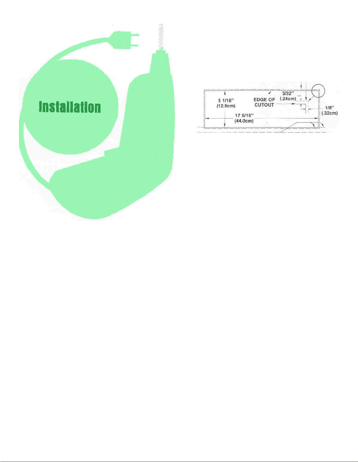
The MAC 4100 is installed from the front of a
custom cabinet. The desirable space behind the
cabinet panel is 15" [38.1 cm] deep, 18-1/2" [47 cm]
wide, and 6"-[15.2 cm] high. The unit fits an opening
exactly 5-1/16" [12.9 cm] by 17-5/16" [44 cm] wide.
Make this cutout carefully. The receiver's front panel
has a 1/8" [.32 cm] overhang on both sides and a
3/32" (.24 cm) overhang on the top and bottom, [see
Fig.
1].
The weight of the receiver must rest on a shelf in
which there is a ventilation hole cutout 15" [38-1 cm]
x 8" [20.32 cm], [see Fig. 2]. In addition, a single 3/8"
to 1/2" [1 cm to 1.3 cm] screw hole [see Fig. 2 and
Fig. 3] must be drilled in the shelf to secure the
receiver after installation. The top of the shelf must
be attached flush with the bottom of the custom
panel cutout.
EDGE OF 4100 FRONT PANEL
BOTTOM OF PANEL CUTOUT AND
TOP OF SUPPORT SHELF MUST COINCIDE
Fig. 1 Custom Cabinet Front Panel Cutout.
Prepare the MAC 4100 for custom mounting by
removing the wood cabinet and feet as follows:
1. Remove 4 screws "A" [see Fig. 4]; two from each
side panel.
2. To remove the enclosure top panel, the receiver's
metal top must be temporarily removed. It is attached to the chassis by 4 screws "B" [see Fig. 4]
installed 2 through the flange on the back and 1
through each of the flanges on the side. Remove
these 4 screws. Save the screws to reinstall the
metal top after removal of the enclosure top
panel.
3. Under the metal top are 5 screws "C" that hold the
enclosure top panel to the metal top [see Fig. 4].
Remove the 5 screws "C" that hold the metal top
to the enclosure top panel.
4. Replace the metal top on the MAC 4100 with the 4
screws "B".
5. On the bottom of the receiver are the 4 plastic feet
held on by screws "D" [see Fig. 4]. Remove these
feet. Do not attempt to remove the 4 plastic button glides as these rest against the shelf, (see Fig.
2 and 3). At this point the receiver is ready to be
custom installed.
From the front of the cabinet, thread the power
cord through the opening in the cabinet panel and
slide the MAC 4100 in on the shelf. Adjust the position to evenly cover the custom panel cutout. Lock
the unit in place with a screw and washer inserted
through the drilled hole in the mounting shelf [see
Fig. 3]. Use a 1-1/4" [3.2 cm] screw for 1/2" [1.3 cm]
shelf or a 1-1/2" [3.8 cm] screw for 3/4 [1.9 cm] shelf.
Do not use longer screws.
3
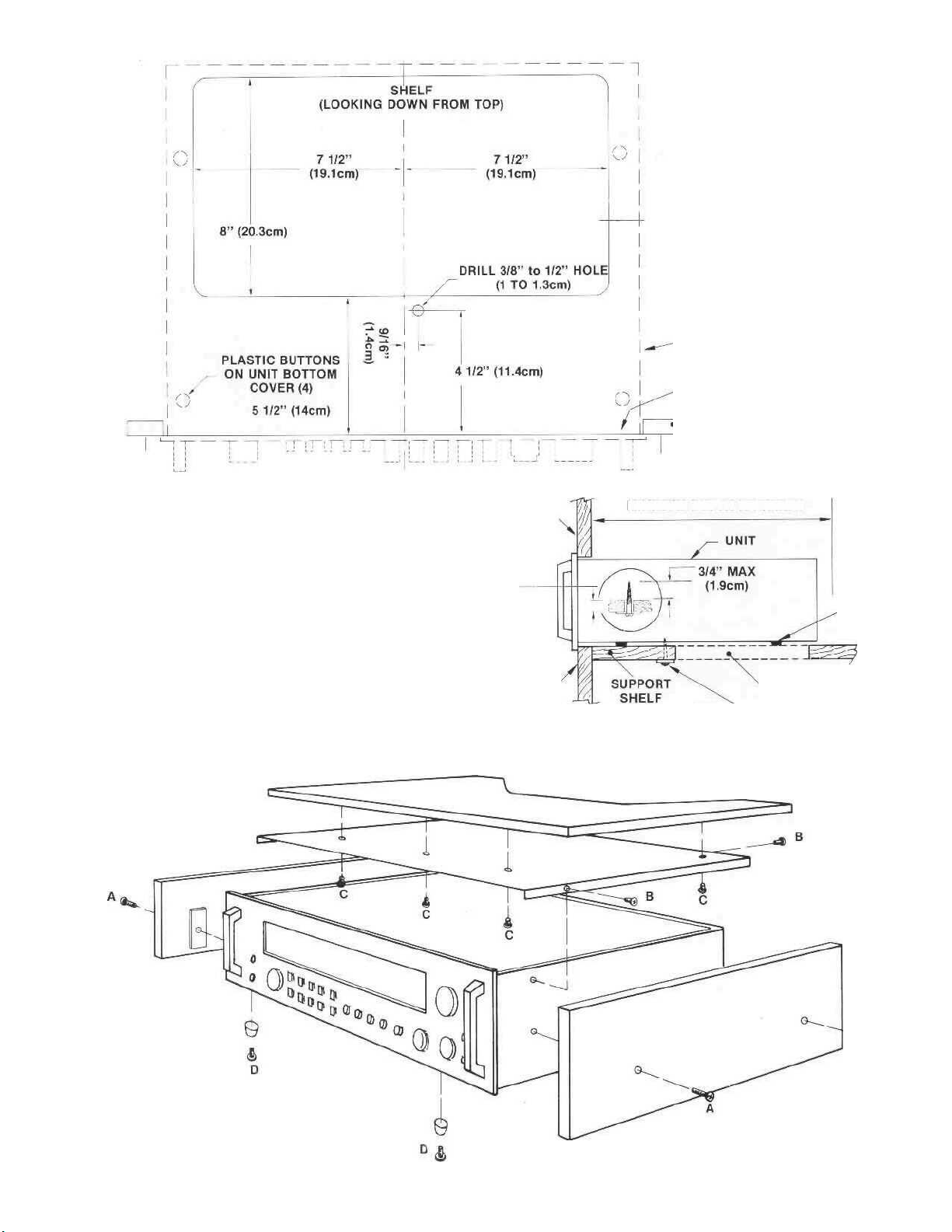
MAC 4100 UNIT OUTLINE (DOTTED)
MOUNTING SURFACE
MOUNTING PANEL
Fig. 2 Custom Cabinet Shelf Mounting Cutout.
FOR 1/2" SHELF USE 1 1/4" SCREW
(1.3cm) (3.2cm)
FOR 3/4" SHELF USE 1 1/2" SCREW
(1.9cm) (3.8cm)
MOUNTING
SURFACE
MOUNTING
PANEL
15" (36.1cm)
MINIMUM DEPTH REQUIRED
PLASTIC
BUTTONS
CUTOUT FOR
VENTILATION
SECURE UNIT
WITH SCREW AND
WASHER
Fig. 3 MAC 4100 Custom Mounting Profile
Fig. 4 MAC 4100 Enclosure Assembly
4

How to Connect
CONNECTING TURNTABLES
The MAC 4100 has shorting plugs in the phono inputs. To prevent unwanted noise remove only the
shorting plugs from input jacks that are 10 be used
Connect the cable from the left channel of the turntable into the INPU1 L PHono 1 jack.
Connect the cable from the right channel of the
turntable into the INPUT R PHono 1 jack. Connect
PHono 2 in the same way for use with a second turn-
table
CONNECTING TAPE RECORDERS
To Record
Connect a cable from the RECORDER L TAPE 1
OUT jack to the left high level input of the tape
recorder. Connect a cable from the RECORDER R
TAPE 1 OUT jack to the right high level input of the
tape recorder. Connect a second recorder in the
same manner to the RECORDER TAPE 2 OUT jacks.
To Playback/Monitor.
Connect a cable from the left channel output of a
tape recorder to the RECORDER L TAPE 1 IN jack.
Connect a cable from the right channel output of a
tape recorder to the RECORDER R TAPE 1 IN jack.
Connect a second recorder in the same manner to
the RECORDER TAPE 2 IN jacks.
Front Panel Tape Recorder Jacks:
Tape recorder inputs and outputs are available at
the TAPE IN-OUT jacks on the front panel left of the
INPUT SELECTOR switch. Rapid, temporary connections to TAPE 2 facilities are easily made without
getting at the rear panel. A metal shielded 1/4"
stereo phone plug is used Connections are tip: left
signal, ring: right signal, and. sleeve: common
ground.
When a tape recorder is plugged into the front
jacks all the facilities normally associated with
TAPE 2 on the rear panel are automatically transferred to the front panel jacks.
CONNECTING AC POWER
The receiver AC power cord is plugged into a 120
volt 6O Hz wall outlet.
There are three types of AC power outlets on the
back panel of the MAC 4100 one red. two black, and
two green
The red and the green AC power outlets are on at
all times. The red outlet can be used for a tape
recorder with its own AC power switch. Plug the AC
power cables from the turntable into the green
TURNTA8LE power outlets on the rear panel
The two black outlets are switched on and off
when the receiver is turned on or off. These are intended for equalizers and other accessories.
The POWER ON pushbutton shares AC power
control, with the AC power switch on a turntable,
through a current detecting switch circuit On me
rear panel the TURNTABLE AUTO/MANUAL switch
selects the mode of operation.
When the switch is in the AUTO position and a
turntable plugged into one of the green AC power
outlets, the AC power to the receiver and to the
black AC power outlets can be controlled by the
turntable on/off switch. When AC power to the turntable is turned on, automatically the receiver and the
SWITCHED black AC power outlets are turned on
The system will remain on until the turntable is turned oil. The POWER ON pushbutton controls the AC
power lor any source other than the turntable.
In the MANUAL position only the POWER ON
pushbutton will turn AC power on or off
Some turntables have electronic circuits that
draw current all the time. To use these turntables the
AUTO/MANUAL switch must be in the MANUAL
position. With the AUTO/MANUAL switch in the
MANUAL position, AC power to the system will be
controlled by the front panel POWER pushbutton
only.
5

The green AC power outlets are protected with a
one amp fuse. Any increase in the value of this fuse
will affect the protection of the sensing circuit and
may cause damage.
CONNECTING PROGRAM SOURCE GROUNDS
A single GROUND post is provided to which
grounds for turntables, record changers, tape decks,
etc. are connected. To prevent hum pickup, the left
and right program cables and the ground wire from
that source should be wound or twisted together.
Make sure the ground wire does not make any connection to the shields of the left and right program
cables between the source and the input of the MAC
4100.
FM PRESELECTOR SWITCH
FM receivers can be overloaded by very large
antenna input signals when the receiver is located
very near to a FM broadcasting station or when a
high gain directional antenna is used in a
metropolitan area.
The preselector may be switched into or out of the
FM RF circuit by a slide switch located on the MAC
4100 rear panel near the AM antenna.
We recommend that the FM Preselector switch be
used in the "out" position for all FM listening condi-
tions except where there is evidence of overload by
strong stations. In that case, the "in" position will
immunize against overload. For most stations there
will be no listening difference between the two
switch positions.
MAC 4100 receivers with serial numbers below
BY3000 do not have the FM preselector switch
described above.
CONNECTING AN FM ANTENNA
One of three antenna systems can be used: [1] an
outdoor FM antenna, or [2] a VHF-TV antenna, or [3]
the indoor dipole supplied.
An outdoor antenna is recommended for optimum
performance in all areas, In fringe [outlying] areas,
best results will be obtained with a highly directional FM antenna used in conjunction with a
rotator. If the antenna uses a 300 ohm lead, connect
it to the ANTENNA 3000 FM push connectors.
The coaxial cable of an unbalanced 75 ohm anten-
na connects to the rear panel ANTENNA 750 FM
type F coaxial connector.
An outside antenna system should not be located
in the vicinity of overhead power lines or other electric light or power circuits, or where it can fall into
such power lines or circuits. When installing an outside antenna system, extreme care should be taken
to keep from touching such power lines or circuits
as contact with them might be fatal.
A VHF-TV antenna can be effective when it is
designed for both FM and TV reception. Connect the
two leads from the VHF-TV antenna to the ANTEN-
NA 300W FM push connectors.
CONNECTING AN INDOOR DIPOLE ANTENNA
The flexible folded dipole antenna [300 ohm] is for
use in urban or high strength signal areas. Connect
the two leads from the dipole to the ANTENNA 300W
FM push connector.
The flexibility of the twin flat wire assembly permits it to be placed under a rug, tacked behind the
stereo ... or placed in any other convenient location.
In some cases, it may be necessary to "position" the
antenna for best signal reception. This should be
done before it is permanently located.
Avoid locating the antenna next to other wires or
metal objects. Any indoor antenna may be ineffective in houses having metal siding or metal foil insulation.
AM ANTENNA
For local and most moderately distant AM reception the built-in ferrite loopstick antenna may be used. The AM loopstick antenna is on a swivel base
and must be adjusted away from the chassis for best
reception.
Distant reception can be improved with the use of
a copper antenna wire 50 to 150 feet in length. Sus-
pend the wire in a straight line as high as possible.
Attach the wire at each end with suitable glass or
ceramic insulators. Connect a lead-in wire at any
convenient point on the antenna. It is recommended
that a lightning arrester be used with an outdoor AM
antenna. The arrester should be well grounded to a
ground rod or cold water pipe.
CONNECTING A MAXIMUM
PERFORMANCE INDICATOR
The scope TP1 and TP2 jacks on the rear panel are
used to connect a Mclntosh maximum performance
indicator or an oscilloscope. Follow directions
outlined in the maximum performance indicator
owner's manual.
FUSES
A 4-amp SLO BLO fuse protects the receiver circuits. The fuse does not protect additional equipment connected to the rear panel AC power outlets.
A one amp fuse protects the turntable auto on circuit. If this fuse opens, power to the green outlets
will be interrupted.
6

7
 Loading...