

McIntosh MA-6700 Owners Manual
McIntosh Laboratory, Inc. 2 Chambers Street Binghamton, New York 13903-2699 Phone: 607-723-3512 www mcintoshlabs.com
MA6700
Integrated Amplifier
MAC6700
Receiver
Owner’s Manual
The lightning ash with arrowhead, within an equilateral
triangle, is intended to alert the user to the presence of
uninsulated “dangerous voltage” within the product’s enclosure that may be of sufcient magnitude to constitute
a risk of electric shock to persons.
The exclamation point within an equilateral triangle is
intended to alert the user to the presence of important
operating and maintenance (servicing) instructions in the
literature accompanying the appliance.
WARNING - TO REDUCE RISK
OF FIRE OR ELECTRICAL
SHOCK, DO NOT EXPOSE
THIS EQUIPMENT TO RAIN OR
MOISTURE.
IMPORTANT SAFETY
INSTRUCTIONS!
PLEASE READ THEM BEFORE
OPERATING THIS EQUIPMENT.
1. Read these instructions.
2. Keep these instructions.
3. Heed all warnings.
4. Follow all instructions.
5. Do not use this apparatus near water.
6. Clean only with a dry cloth.
7. Do not block any ventilation openings. Install
in accordance with the manufacturer’s instructions.
8. Do not install near any heat sources such as
radiators, heat registers, stoves, or other appa-
ratus (including ampliers) that produce heat.
9. Do not defeat the safety purpose of the polarized or grounding-type plug. A polarized plug
has two blades with one wider than the other.
A grounding type plug has two blades and a
NO USER-SERVICEABLE PARTS
INSIDE. REFER SERVICING TO
QUALIFIED PERSONNEL.
third grounding prong. The wide blade or the
third prong are provided for your safety. If
the provided plug does not t into your outlet,
consult an electrician for replacement of the
obsolete outlet.
10. Protect the power cord from being walked on
or pinched particularly at plugs, convenience
receptacles, and the point where they exit
from the apparatus.
11. Only use attachments/accessories specied by
the manufacturer.
12. Use only with the cart, stand, tripod, bracket,
or table specied by the manufacturer, or sold with the apparatus. When a cart is used, use
caution when moving the cart/
apparatus combination to avoid
injury from tip-over.
13. Unplug this apparatus during lightning storms
or when unused for long periods of time.
14. Refer all servicing to qualied service personnel. Servicing is required when the apparatus
has been damaged in any way, such as power-
To prevent the risk of electric
shock, do not remove cover or
back. No user-serviceable parts
inside.
supply cord or plug is damaged, liquid has
been spilled or objects have fallen into the
apparatus, the apparatus has been exposed to
rain or moisture, does not operate normally, or
has been dropped.
15. Do not expose this equipment to dripping or
splashing and ensure that no objects lled
with liquids, such as vases, are placed on the
equipment.
16. To completely disconnect this equipment from
the a.c. mains, disconnect the power supply
cord plug from the a.c. receptacle.
17. The mains plug of the power supply cord shall
remain readily operable.
18. Do not expose batteries to excessive heat such
as sunshine, re or the like.
19. Connect mains power supply cord only to a
mains socket outlet with a protective earthing
connection.
2
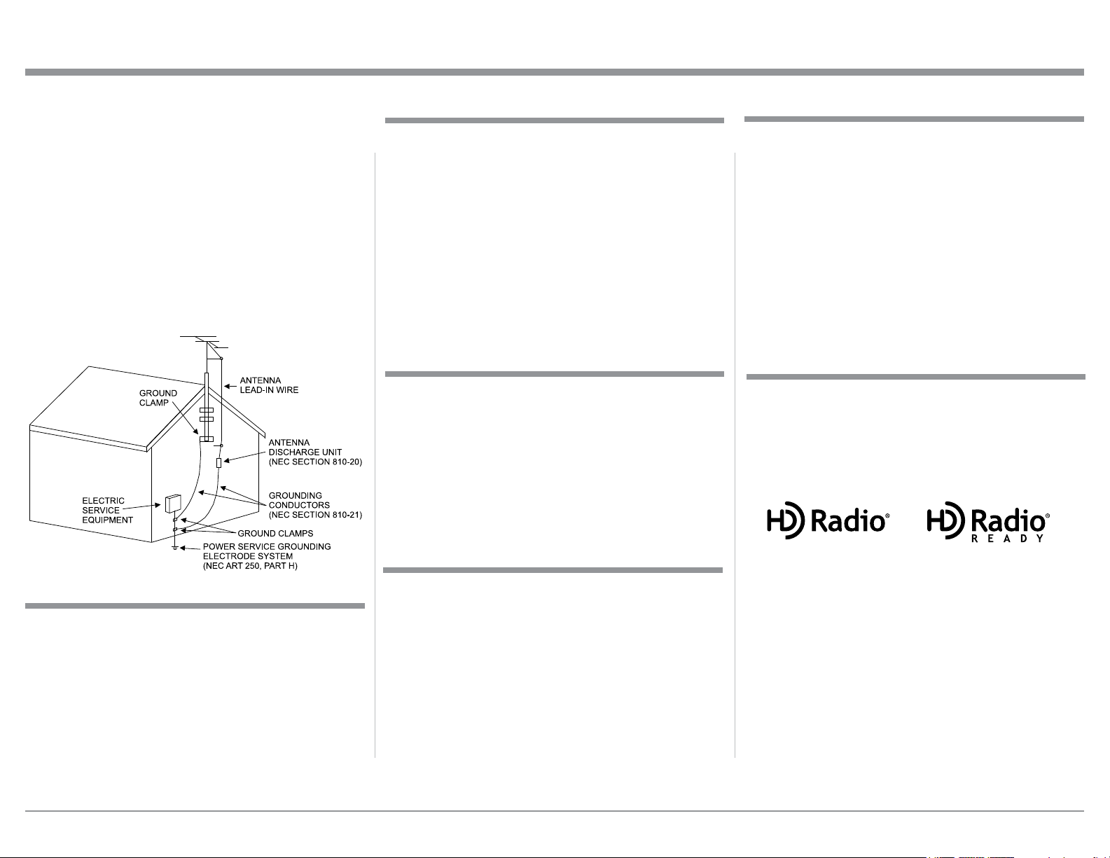
Outdoor Antenna Grounding
If an outside antenna or cable system is connected to the
product, be sure the antenna or cable system is grounded
so as to provide some protection against voltage surges
and built-up static charge. Article 810 of the National
Electrical Code, ANSI/NFPA 70, provides information
with regards to proper grounding of the mast and supporting structure, grounding of the lead-in wire to an
antenna discharge unit, and size of ground conductors,
location of antenna-discharge unit, connection to ground
electrodes and requirements for the grounding electrode.
Example of antenna grounding as perNational
Electrical Code, ANSI/NFPA 70
Important Information
This Owner’s Manual covers the McIntosh MA6700
Integrated Amplifier and the McIntosh MAC6700
Receiver. The Preamplifer and Power Amplifier Circurity is identical in both models.
The MA6700 Integrated Amplifier allows for an
optional Tuner Module to be installed at any time. The
MAC6700 Receiver comes with the Tuner Module
already installed from the factory.
When the information contained in this Owner’s
Manual refers to both models, MA6700 (with or with-
out the Tuner Model installed) and MAC6700, it will
be refered to as MA/MAC6700.
Customer Service
If it is determined that your McIntosh product is in
need of repair, you can return it to your Dealer. You
can also return it to the McIntosh Laboratory Service
Department. For assistance on factory repair return
procedure, contact the McIntosh Service Department
at:
McIntosh Laboratory, Inc.
2 Chambers Street
Binghamton, New York 13903
Phone: 607-723-3515
Fax: 607-723-1917
Thank You
Your decision to own this McIntosh MA6700 Integrated Amplifier or MAC 6700 Receiver ranks you
at the very top among discriminating music listeners.
You now have the best. The McIntosh dedication to
precision performance assures many years of musical
enjoyment.
Please take a short time to read the information in
this manual. We want you to be as familiar as possible with all the features and functions of your new
McIntosh.
Please Take A Moment
The serial number, purchase date and McIntosh Dealer
name are important to you for possible insurance
claim or future service. The spaces below have been
provided for you to record that information:
Serial Number: _______________________________
Purchase Date: _______________________________
Dealer Name: ________________________________
Technical Assistance
If at any time you have questions about your McIntosh
product, contact your McIntosh Dealer who is familiar
with your McIntosh equipment and any other brands
that may be part of your system. If you or your Dealer
wish additional help concerning a suspected problem,
you can receive technical assistance for all McIntosh
products at:
McIntosh Laboratory, Inc.
2 Chambers Street
Binghamton, New York 13903
Phone: 607-723-3512
Fax: 607-724-0549
Trademark and License Information
The McIntosh MA/MAC6700 and TM2 Tuner Module
incorporates copyright protected technology that is
protected by U.S. patents and other intellectual property rights. The MA6700 with optional TM2 Tuner
Module and the MAC6700 with TM2 Tuner Module
uses the following Technologies:
HD Radio™, HD Radio Ready™, and the HD
Radio Ready logo are proprietary trademarks
of iBiquity Digital Corporation.
HD Radio Technology manufactured under
license from iBiquity Digital Corporation. U.S.
and Foreign Patents. HD Radio™ and the
HD, HD Radio, and “Arc” logos are proprietary trademarks of iBiquity Digital Corp.
Copyright 2012, 2013 © by McIntosh Laboratory, Inc.
3

Table of Contents
Safety Instructions ............................................................ 2-3
Thank You and Important Information ............................... 3
Please Take a Moment, Technical Assistance .................... 3
Customer Service, Trademark and License Information .... 3
Table of Contents ................................................................. 4
General Information .........................................................4 -5
Connector and Cable Information ....................................... 5
Introduction ......................................................................... 6
Amplifier Performance Features .........................................6
Tuner Module Performance Features .................................. 7
Dimensions .......................................................................... 8
Installation ........................................................................... 9
Connections:
Amplifier/Receiver Rear Panel Connections .................... 10
(Separate Sheet) ...........................................................Mc1A
Tuner Module and RAA2 Antenna Connections .............. 11
Connecting Antennas (Separate Sheet) ..................... Mc1B
Connecting Components ................................................... 12
Connection Diagrams (Separate Sheet) .................Mc2A/2B
Passthru Connections ........................................................ 13
Connecting Loudspeakers ............................................ 14-15
Connecting for Bi-Amplification ...................................... 16
Remote Control and Front Panel:
Remote Control Push-buttons ........................................... 18
How to use the Remote Control .........................................19
Front Panel Displays, Controls,
Push-buttons and Jack ....................................................... 20
Setup Mode:
How to Operate the Setup Mode ....................................... 21
Default Settings .......................................................... 21
Fi r mware Ve r sio n ....................................................... 22
Source Input Reassigment .......................................... 23
Source Input Renaming .............................................. 24
Passthru ...................................................................... 24
Power Control Triggers 1 and 2 .................................. 24
Comm Port Baud Rate ................................................25
Remote Control Codes ............................................... 26
Power Mode ................................................................ 26
TM2 Tuner Module Firmware Version ...................... 27
TM2 Tuner Module Clear Presets .............................. 27
TM3 Tuner Module Firmware Version ...................... 28
TM3 Tuner Module Clear Presets .............................. 28
TM3 Tuner Regions .................................................... 29
Amplifier Operation:
How to Operate the MA/MAC6700 .................................. 30
Power On/Off ............................................................. 30
Source Selection ......................................................... 30
Volume Control ..........................................................30
Trim Functions:
Balance, Bass, Treble ........................................ 31
Trim Level and Tone Control ............................32
Mono/Stereo Mode and Phono Adjustments .... 33
Display Brightness and Digital Audio Display 33
Meter Backlight and Tuner Control .................. 34
Tuner Text and Tuner Blend Mode ................... 35
Tone Bypass, Trim, Mute ........................................... 35
Headphone Jack and Power Output Meters................36
Power Guard and How to Make a Recording .............36
Using a Separate Power Amplifier ............................. 36
Using Output 2 and Passthru ...................................... 37
USB Input Operation with a Computer ...................... 37
Reset of Microprocessors ........................................... 37
Resetting the MA/MAC6700 to default settings ....... 37
TM2 and TM3 Tuner Operation:
Operating the TM2 and TM3 Tuner .................................. 39
AM or FM Band Selection ......................................... 39
Manual Tuning ........................................................... 39
Preset Tuning .............................................................. 39
Creating Presets ...................................................40
Clearing Presets...................................................40
Automatic Tuning ....................................................... 40
Direct Access Tuning ................................................. 41
Stereo/Mono Mode ..................................................... 41
Text information ......................................................... 41
HD Radio Reception .................................................. 41
Manual HD Radio Program Selection .............. 442
Selecting HD Radio Program Preset .................. 40
Specifications ....................................................... 43-46
Packing Instructions ................................................. 47
General Information
1. For additional connection information, refer to the
owner’s manual(s) for any component(s) connected
to the MA/MAC6700.
2. Apply AC Power to the MA/MAC6700 and other
McIntosh Component(s) only after all the system
components are connected together. Failure to do
so may cause a malfunction of system operations as
the Microprocessor’s Circuitry inside the components is active when AC Power is applied.
3. The MA/MAC6700 includes an Auto Off Power
Save Feature and the default setting is enabled.
For additional information including how to disable
it, refer to page 26.
4. The type and availability of the optional Tuner
Module for the MA6700 (sold separately) and the
factory installed Tuner Module in the MAC6700
varies from country to country. Contact your McIntosh Dealer for additional information.
5. When Power Amplifier Protection Circuitry of
the MA/MAC6700 has activated, the Front Panel
Power Guard LEDs are illuminated continuously
and the sound will be muted.
6. When the Power Transformer has overheated due
to improper ventilation and/or high ambient operating temperature, AC Power is removed from
the MA/MAC6700. Normal operation will resume
when the operating temperature is in a safe range
again.
7. For the best performance and safety, it is important
to always match the impedance of the Loudspeaker
to the Power Amplifier connections. Refer to pages
14 thru 16.
Note: The impedance of a Loudspeaker actually var-
ies as the Loudspeaker reproduces different
frequencies. As a result, the nominal impedance
rating of the Loudspeaker (usually measured at
a midrange frequency) might not always agree
4
General Information, Connector and Cable Information
with the impedance of the Loudspeaker at low
frequencies where the greatest amount of power
is required. Contact the Loudspeaker Manufacturer for additional information about the actual
impedance of the Loudspeaker before connecting
it to the McIntosh MA/MAC6700.
8. The MA/MAC6700 Remote Control is capable of
operating other components. For additional information go to www.mcintoshlabs.com.
9. The IR Input, with a 1/8 inch mini phone jack, is
configured for non-McIntosh IR sensors such as
a Xantech Model HL85BK Kit. Use a Connection
Block such as a Xantech Model ZC21 when two or
more IR sensors need to be connected to the MA/
MAC6700. The signal from a connected External
IR Sensor will have priority over the signal from
the Front Panel IR Sensor.
10. When discarding the unit, comply with local rules
or regulations. Batteries should never be
thrown away or incinerated but disposed
of in accordance with the local regulations concerning battery disposal.
11. For additional information on the MA/MAC6700
and other McIntosh Products please visit the McIntosh Web Site at www.mcintoshlabs.com.
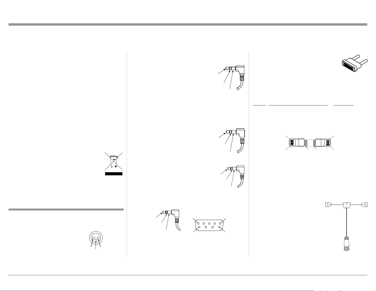
Connector and Cable Information
XLR Connectors
Below is the Pin configuration for the XLR Balanced
Input Connectors on the MA/MAC6700. Refer to the
diagram for connection:
PIN 1: Shield/Ground
PIN 2: + Output
PIN 3: - Output
PIN 1
PIN 3
PIN 2
Power Control and Trigger Connectors
The Power Control Trigger Output Jacks send and
Passthru Input Jack receives Power
On/Off Signals (+12 volt/0 volt)
when connected to other McIntosh
Components. An additional connection is for controlling the illumination of the Power Output Meters
Main, Trig 1&2
and Pass-Thru
Power
Control
Meter
Illumination
Control
Ground
on McIntosh Power Amplifiers. A
3.5mm stereo mini phone plug is used for connection
to the Power Control, Trigger and Passthru Outputs.
Data Port Connectors
The Data Out Ports send Remote Control Signals to
Source Components. A 3.5mm stereo
mini phone plug is used for connection.
IR IN Port Connectors
Data
Signal
N/C
Data
Ground
The IR IN Port also uses a 3.5mm stereo mini phone
plug and allows the connection of
other brand IR Receivers to the MA/
MAC6700.
IR Data
Control
N/C
Ground
RS232-C Data Port Cable
The RS232 Data Cable is a 3.5mm stereo mini phone
plug to a sub minature DB 9 connector:
DB9
Data In
(DB9-pin2)
Data Out
(DB9-pin3)
Ground
(DB9-pin5)
(male connector)
PIN 1
PIN 6
PIN 5
PIN 9
McIntosh Plug-In Jumper Connector
The MA/MAC6700 utilizes a phono style Plug-In
Jumper to connect the Preamplifier
Output to the Power Amplifier Input, one
Jumper for each channel.
Note: The Jumper Connector is available
from the McIntosh Parts Department:
McIntosh Jumper Connector Part No. 117781
RAA2 Cable Connector
Pin No. Wire Color Pin No. Wire Color
1. White/Orange 5. White/Blue
2. Orange 6. Green
3. White/Green 7. White/Brown
4. Blue 8. Brown
*Cable outer shield
Pin 8
Pin 1
*Cable outer shield
Pin 1
Pin 8
Note: The RAA2 Connecting Cable is available from the
McIntosh Parts Department:
RAA2 Antenna Cable Part No. 171844
Twenty foot, shielded 8 conductor, with a shielded
RJ45 connector on each end.
FM Dipole Antenna
The MAC6700 Tuner Module or the addition of the
optional Tuner Module for the
MA6700 require the connection of an external Antenna for
FM reception. A “FM Dipole
Antenna” is available from the
McIntosh Parts Department:
FM Dipole Antenna Part
No. 173033
5

Introduction
Now you can take advantage of traditional McIntosh
standards of excellence in the MA6700 Integrated
Amplifier or MAC6700 Receiver. The Power Amplifier section of the MA/MAC6700, with a power output
of 200 watts per channel, will drive a pair of quality
Loudspeakers to a high level of performance.
The flexible Preamplifier section provides connec-
tions for various input sources and may also be used to
drive an external Power Amplifier(s).
The MAC6700 tuner circuitry delivers the same
exceptional performance as a stand-alone McIntosh
Tuner. The MA6700 has provisions for adding an
optional McIntosh AM/FM Tuner Module. The Tuner
Module can be installed by your McIntosh Service
Dealer at any time, usually while you wait.
The MA/MAC6700 reproduction is sonically
transparent and absolutely accurate. The McIntosh
Sound is “The Sound of the Music Itself.”
Amplifier Performance Features
• Power Output with Patented Autoformer
The MA/MAC6700 consists of a 200 watts per channel stereo Power Amplifier with less than 0.005%
distortion. The McIntosh designed and manufactured
Autoformer allows connection of 2, 4 or 8 ohm Loudspeakers. The Power Amplifier uses ThermalTrak1
Output Transistors for lower distortion and cool operation.
• Power Guard
The patented McIntosh Power Guard circuit prevents
amplifier clipping and protects your valuable Loudspeakers.
1
ThermalTrak™ and ON Semiconductor are trademarks of Semi-
conductor Components Industries, LLC
• Sentry Monitor and Thermal Protection
McIntosh Sentry Monitor power output stage protection circuits ensure the MA/MAC6700 will have a
long and trouble free operating life. Built-in Thermal
Protection Circuits guard against overheating.
• Electronic Switching and Balanced Connections
The Preamplifier uses Logic Circuits controlling
Electromagnetic Switches on all inputs and operating functions for reliable, noiseless, distortion free
switching. There is a Balanced Input for connection of
source components.
• Digital Audio Inputs
The MA/MAC6700 has Coaxial, Optical and USB
Digital Inputs to Decode PCM Signals from an
external source. The MA/MAC6700 Up Samples the
Digital Signal to 192kHz with 32Bit resolution before
the Digital to Analog process begins.
• Moving Coil and Moving Magnet Phono Inputs
The MA/MAC6700 contains two different precision
Phono Preamplifier Circuits. One for low output Moving Coil Phono Cartridges with selectable resistance
loading, the other is for Moving Magnet Cartridges.
Both circuits use the latest designs to provide the
lowest possible noise and distortion. The RIAA Correction Equalization Circuitry utilizes close tolerance
resistors and capacitors for an extremely flat frequency response.
• Multifunction Fluorescent Display
The Front Panel Display indicates source selection,
volume levels, tone adjustments and setup functions.
• Illuminated Power Meters
The Illuminated Power Output Watt Meters on the
MA/MAC6700 are peak responding, and indicate the
power output of the amplifier.
• PassThru Mode
The Automatic PassThru Mode allows the MA/
MAC6700 to become part of a Multichannel Sound
System for DVD-Audio, SACD and Home Theater
Movies.
• Power Control and Remote Control
The Power Control Output connection provides convenient Turn-On/Off of McIntosh Source Components.
The Data Ports together with the supplied Remote
Control provide control of McIntosh Source Components connected to the MA/MAC6700.
• Special Power Supply
The large Power Transformer, multiple filter capacitors with 120 Joules of Energy Storage and regulated
Power Supply ensures stable noise free operation even
though the power line varies.
• McIntosh Custom Binding Posts
McIntosh Patented gold plated output terminals deliver
high current output. They accept large diameter wire
and spade lugs. Banana plugs may also be used only in
the United States and Canada.
• Fiber Optic Solid State Front Panel Illumination
The even Illumination of the Front Panel is accomplished by the combination of custom designed Fiber
Optic Light Diffusers and extra long life Light Emit-
ting Diodes (LEDs). The glass Front Panel ensures the
pristine beauty of the MA/MAC6700 will be retained
for many years.
6

Connector Information, Introduction, Amplifier Performance Features and Tuner Modules Performance Features
TM2 Tuner Module Performance Features
• Reception
The TM2 Tuner Module with HD Radio Technology
allows for the reception of high quality FM and AM
Radio Broadcasts in regions where available.
Digital, CD-quality sound. HD Radio Technology
enables local radio stations to broadcast a clean digital
signal. AM sounds like today’s FM and FM sounds
like a CD.
Adjacent to traditional main stations are extra local
FM channels. These HD2/HD3 Channels provide new,
original music as well as deep cuts into traditional
genre.
Program Service Data: Contributes to the superior
user experience of HD Radio Technology. Presents
song name, artist, station IDs, HD2/HD3 Channel
Guide, and other relevant data streams.
• Special FM RF Circuitry
The Tuner Module RF Circuitry receives strong local
FM Station Signals without distortion and receives
even the weakest of FM Signals with low noise.
• High Dynamic Range IF FM Circuitry
The all important IF circuitry in the Tuner Module
provides dynamic bandwidth control optimizing
performance at all times with varying reception conditions.
• RAA2 External AM Antenna
The RAA2 External AM Antenna provides the perfect
match to the Tuner Module AM Circuitry. The 20 foot
(6 meter) connection cable allows placement of the
AM Antenna away from electronic equipment which
can produce RF Interference to weak AM signals.
• Preset Stations and Permanent Memory
Twenty AM and Twenty FM station presets make it
easy to listen to your favorite stations. Station Presets and Function Modes are retained in Permanent
Memory even when AC power is switched Off.
• Multifunction Fluorescent Display
The Front Panel Display indicates Station Frequency,
Signal Strength, Stored Station Presets and Tuner
Setup Functions.
TM3 Tuner Module Performance Features
• Reception
In those regions where HD Radio Technology is not
available, the TM3 Tuner Module provides superb
reception of conventional FM and AM Radio Broadcasts.
• Special FM RF Circuitry
The Tuner Module RF Circuitry receives strong local
FM Station Signals without distortion and receives
even the weakest of FM Signals with low noise.
• High Dynamic Range IF FM Circuitry
The all important IF circuitry in the Tuner Module
provides dynamic bandwidth control optimizing
performance at all times with varying reception conditions.
• Information Service
With this optional tuner module installed in the
MA6700 and with the MAC6700, the Front Panel
Display can display various text information from the
Broadcast Station1. This text information may include
the Station Call Sign, Music Genre, Artist Name and
Song Title.
• Preset Stations and Permanent Memory
Twenty AM and Twenty FM station presets make it
easy to listen to your favorite stations. Station Presets and Function Modes are retained in Permanent
Memory even when AC power is switched Off.
• RAA2 External AM Antenna
The RAA2 External AM Antenna provides the perfect
match to the Tuner Module AM Circuitry. The 20 foot
(6 meter) connection cable allows placement of the
AM Antenna away from electronic equipment which
can produce RF Interference to weak AM signals.
• Multifunction Fluorescent Display
The Front Panel Display indicates Station Frequency,
Signal Strength, Stored Station Presets and Tuner
Setup Functions.
1
The display of text information is dependent on the Broadcast
Station transmitted signal, the text information language and
the Broadcast Station country of origin. The Tuner Module supports English Language Alphabet Characters.
7
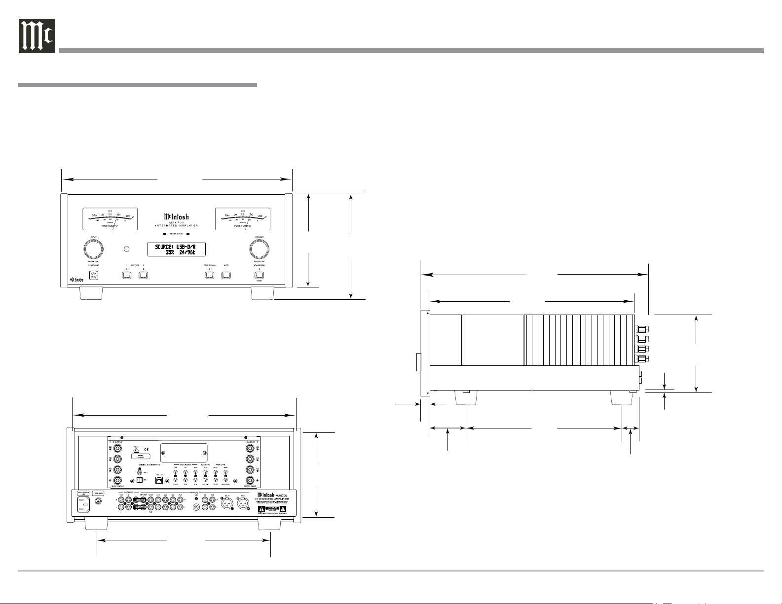
Dimensions
The following dimensions can assist in determining
the best location for your MA/MAC6700. There is
additional information on the next page pertaining to
installing the MA/MAC6700 into cabinets.
Front View of the MA/MAC6700
17-1/2"
44.5cm
Dimensions
Rear View of the MA/MAC6700
16-1/16"
40.8cm
7 -1/8"
18.1cm
6"
15.2cm
7 -5/8"
19.4cm
29/32"
1.8cm
1-5/8"
4.1cm
Side View of the MA/MAC6700
18-3/4"
47.6cm
16-1/2"
41.9cm
13"
33cm
1"
2.5cm
3/16"
0.5cm
6-1/4"
15.9cm
12-3/16"
31cm
8
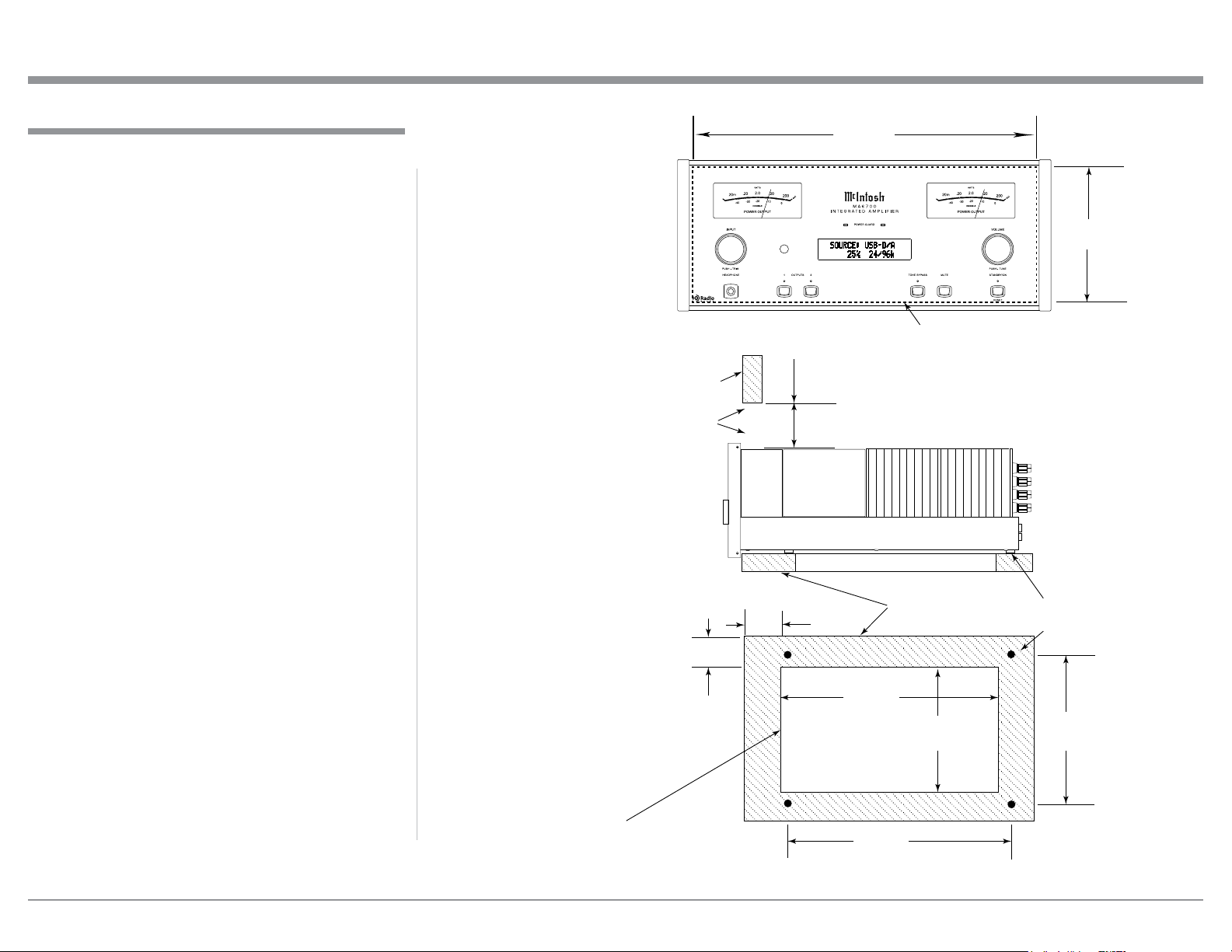
Installation
Installation
The MA/MAC6700 can be placed upright on a table
or shelf, standing on its four feet. It also can be custom
installed in a piece of furniture or cabinet of your
choice. The four feet may be removed from the bottom
of the MA/MAC6700 when it is custom installed as
outlined below. The four feet together with the mounting screws should be retained for possible future use
if the MA/MAC6700 is removed from the custom
installation and used free standing. The required panel
cutout, ventilation cutout and unit dimensions are
shown.
Always provide adequate ventilation for your MA/
MAC6700. Cool operation ensures the longest possible operating life for any electronic instrument. Do not
install the MA/MAC6700 directly above a heat generating component such as a high powered amplifier. If
all the components are installed in a single cabinet, a
quiet running ventilation fan can be a definite asset in
maintaining all the system components at the coolest
possible operating temperature.
A custom cabinet installation should provide the
following minimum spacing dimensions for cool
operation.
Allow at least 6 inches (15.24cm) above the top, 2
inches (5.08cm) below the bottom and 2 inch (5.1cm)
on each side of the Integrated Amplifier, so that air-
flow is not obstructed. Allow 20 inches (50.8cm) depth
behind the front panel. Allow 1-7/6 inch (3.66cm) in
front of the mounting panel for knob clearance. Be
sure to cut out a ventilation hole in the mounting shelf
according to the dimensions in the drawing.
MA/MAC6700 Front Panel
Custom Cabinet Cutout
Opening
for Ventilation
MA/MAC6700 Side View
in Custom Cabinet
MA/MAC6700 Bottom View
in Custom Cabinet
Cabinet
Front
Panel
2"
5.1cm
6"
15.2cm
17-1/16"
43.34cm
Cutout Opening for Custom Mounting
Cutout Opening for Ventilation
Support
1"
2.5cm
Shelf
14-1/2"
36.8cm
Cutout
Opening
for
Ventilation
13"
33cm
6 -5/8"
16.83cm
Chassis
Spacers
15-1/16"
38.3cm
Note: Center the cutout Horizontally
on the unit. For purposes of
clarity, the above illustration
is not drawn to scale.
13-5/16"
33.8cm
9
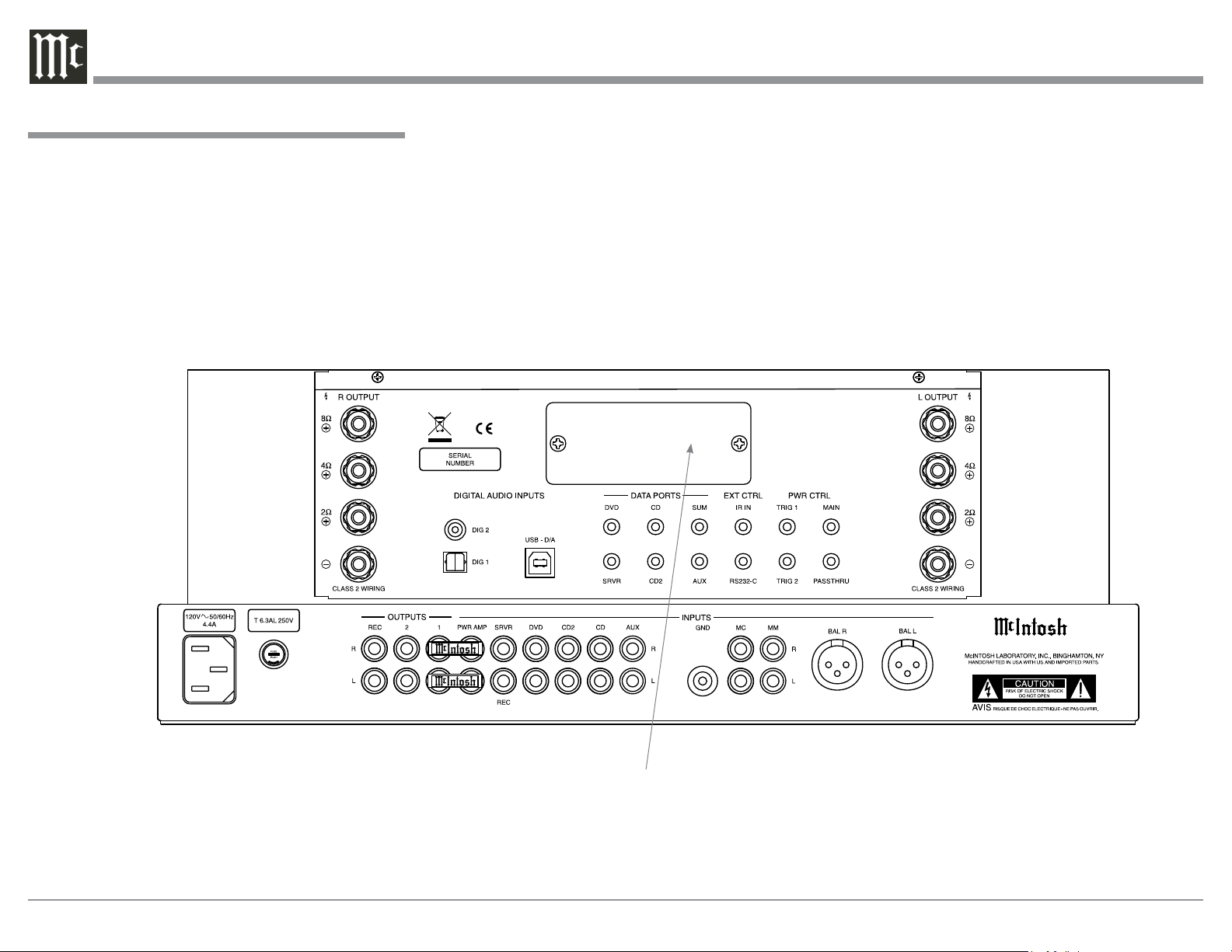
Rear Panel Connections
The identification of Rear Panel Connections for the
MA6700 Integrated Amplifier and MAC6700 Receiver are located on a separate folded sheet contained in
the Owner’s Manual Packet.
Refer to separate sheet “Mc1A” for the Rear Panel
Connections and the next page for information on
McIntosh Tuner Modules for the MA/MAC6700 .
MA6700 Integrated Amplifer and MAC6700 Receiver Rear Panel
MA6700 and MAC6700 Rear Panel Connections
10
MA6700 / MAC6700
Reserved for the installation
of optional Tuner Module
for the MA6700. A Tuner
Module is factory installed
in the MAC6700.
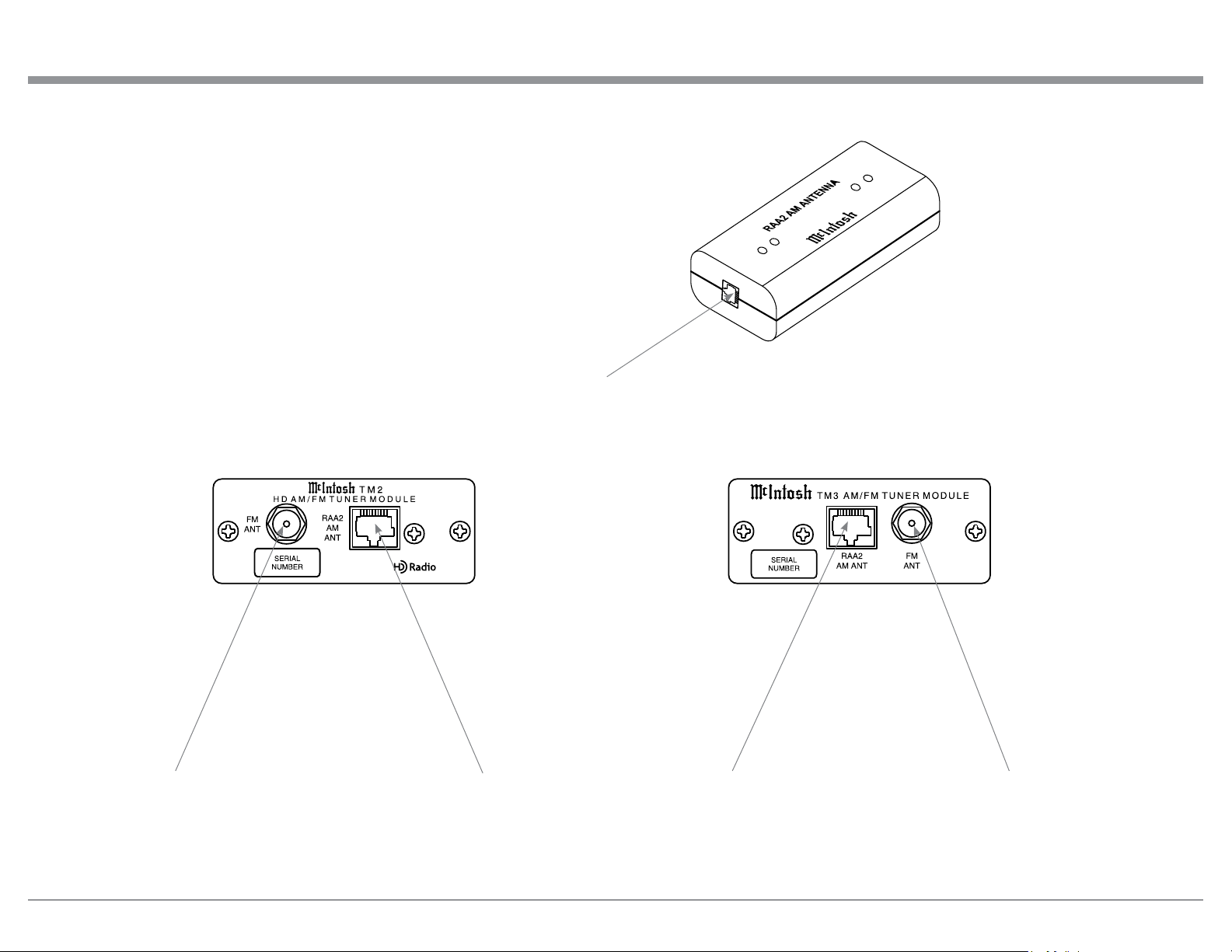
AM ANT (Antenna) connector
to a McIntosh Tuner Module
Tuner Modules and RAA2 Rear Panel Connections
Connection for external FM Antenna Connection for McIntosh RAA2 AM external antenna
Connection for external FM Antenna
11

Connecting Components
The MA/MAC6700 has the ability to automatically
switch power On/Off to McIntosh Source Compo-
nents via the Power Control (Trigger) connections.
The Data Port Connections allow for the remote
operation of basic functions using the MA/MAC6700
Remote Control. With an external sensor connected
to the MA/MAC6700, remote control operation of the
system is possible from another room and/or when the
MA/MAC6700 is located in a cabinet with the doors
closed.
If the optional Tuner Module is to be installed into
the MA6700 (the MAC6700 Tuner Module is factory
installed) please proceed at this time to the installation procedure located on the separate folded sheet
“Mc1B”.
The connection instructions below, together
with the MA/MAC6700 Input and Output Connection Diagrams located on the separate folded sheet
“Mc2A/2B”, are an example of a typical audio
system. Your system may vary from this, however the
actual components would be connected in a similar
manner. For additional information refer to “Connector and Cable Information” on page 5.
Note: Source components may be connected to the
MA/MAC6700 Balanced Inputs or Digital Inputs
instead of Unbalanced Inputs. Refer to Setup
“Reassigning Inputs” to activate them on page
22.
Power Control Connections:
1. Connect a Control Cable from the MA/MAC6700
PWR CTRL (Power Control) MAIN Jack to the
Power Control In on the Turntable.
2. Connect a Control Cable from the McIntosh Turntable Power Control Out Jack to the Audio/Video
Player Power Control In Jack.
3. Connect a Control Cable from the Audio/Video
Player Power Control Out Jack to the SACD/CD
Player Power Control In Jack.
4. Optionally connect a Control Cable from the MA/
MAC6700 PWR CTRL (Power Control) TRIG
(Trigger) 2 Jack to the Power Amplifier (Secondary Room) Power Control In Jack.
Note: The default setting for the TRIG 2 Jack is
“MAIN”. Refer to Setup “Power Control Triggers 1 and 2” on page 24 to change TRIG 2 setting to “OUTPUT 2”.
5. Connect any additional McIntosh Components in a
similar manner, as outlined in steps 1 thru 3.
Data Control Connections:
6. Connect a Control Cable from the MA/MAC6700
CD DATA PORT Jack to the SACD/CD Player
Data In Jack.
7. Connect a Control Cable from the MA/MAC6700
DVD DATA PORT Jack to the Audio/Video
Player Data In Jack.
8. Connect any additional McIntosh Components in
a similar manner, as outlined in steps 6 thru 7.
Sensor Connection:
9. Optionally, connect the cable with stereo mini
plug coming from the compatible External Sensor
to the EXT CTRL (External Control) IR IN Jack
on the MA/MAC6700. Refer to page 5 “General
Information, note 7” for additional information.
Audio Connections:
10. Connect Balanced Cables from the MA/MAC6700
BAL (Balanced) L & R Connectors to the SACD/
CD Player Fixed Audio Output Balanced Connectors.
11. Connect Audio Cables from the MA/MAC6700
DVD INPUT Jacks to the Audio/Video Player
Output Jacks.
Connecting Components
12. Connect the Audio Cables coming from the Turntable to the MA/MAC6700 MC (for a Moving Coil
Cartridge) or MM (for a Moving Magnet Cartidge)
INPUT Jacks.
13. Optionally, connect Audio Cables from the MA/
MAC6700 OUTPUT 2 Jacks to the Power Ampli-
fier (Secondary) Input Jacks.
14. Connect any additional Components in a similar
manner, as outlined in steps 10 thru 13.
Optional Digital Audio Connections:
15. Connect a Coaxial Cable from the MA/MAC6700
DIG (Digital) 1 Digital Audio Input Jack to the
Digital Out Coaxial Jack on the Audio/Video
Player.
16. Connect an Optical Cable from the MA/MAC6700
DIG (Digital) 2 Digital Audio Input connector to
the Digital Audio Out Optical Connector on the
SACD/CD Player.
Optional USB Connection:
17. Connect a USB cable with (type A to type B) connectors from the MA/MAC6700 USB D/A Digital
Audio Input to an available USB connector.
Ground Connections:
18. Connect the Ground Cable coming from the Turntable to the MA/MAC6700 GND Binding Post.
Notes: 1. If the MA/MAC6700 is part of a Home Theater
System, proceed to “PassThru” connection on
page 13.
2. When the MA/MAC6700 will used together
with a separate Power Amplifier for Bi-Amplification of a Loudspeaker System, proceed
page 16.
12
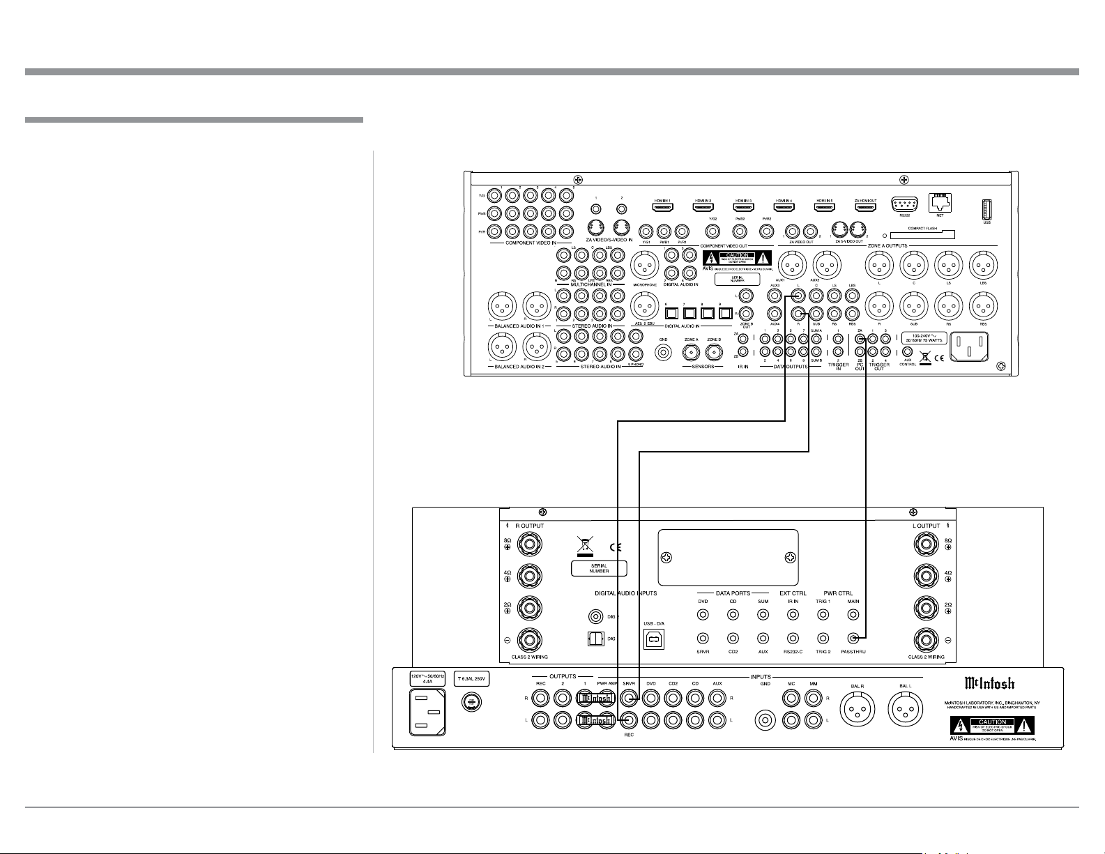
Passthru Connections
The MA/MAC6700 can be part of a Multichannel
Sound System for SACD, DVD-Audio and Home
Theater. The Right and Left Front Channels from an
Audio/Video Control Center can “Passthru” the MA/
MAC6700. In the following example the SRVR Input
will become the “Passthru” input:
1. Connect Audio Cables from the A/V Control
Center Front Left and Right Channel Outputs to
the MA/MAC6700 SRVR Input Left and RightJacks.
2. Connect a Control Cable from the A/V Control
Center ZA (Zone A) PC (Power Control) Output
to the MA/MAC6700 PWR CTRL (Power Con-
trol) PASSTHRU Input Jack.
Note: Refer to Setup “Passthru” on page 24 to assign
the SRVR Input as the “Passthru” Input.
3. Proceed to “Connecting Loudspeaker” on
Page 14.
Passthru Connections
A/V Control Center
MA6700 / MAC6700
13
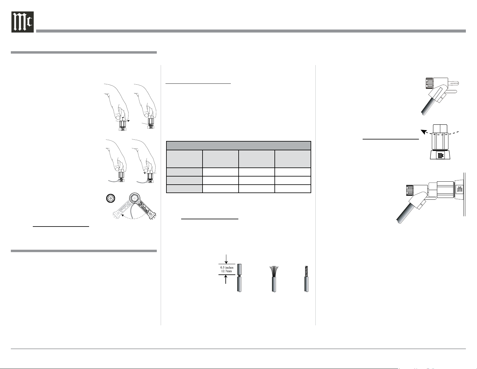
Output Terminals
When connecting the Loudspeaker Hookup Cables to
the MA/MAC6700 Amplifier Output Terminals please
follow the steps below:
1. Rotate the top of the Output Terminal Post counterclockwise until an opening
appears. Refer to gures A and
B.
2. Insert the Loudspeaker hookup
cable into the Output Terminal
Post opening or the cable spade
lug around the center post of
Figu re A
Opening
Figu re B
the Output Terminal. Refer to
gure C.
3. Rotate the top of the Output
Terminal Post clockwise until it
is nger tight. Refer to gure D.
4. Place the supplied McIntosh
Figu re C Figu re D
Wrench over the top of the Output Terminal and rotate it one
quarter of a turn (90° ) to secure
the Loudspeaker Cable Connection. Do not over tighten. Refer
Figu re E
to gure E.
How to Connect Loudspeakers
Caution: Do not connect the AC Power Cord to the MA/
MAC6700 Rear Panel until after the Loudspeaker Connections are made. Failure to
observe this could result in Electric Shock.
The connection instructions below, together with the
MA/MAC6700 Connection Diagram located on the
separate folded sheet “Mc2B”, is an example of a typical audio system. Your system may vary from this,
however the actual components would be connected in
a similar manner. For additional information refer to
“Connector and Cable Information” on page 5.
The McIntosh MA/MAC6700 Power Amplifier Circuitry is designed for Loudspeakers with an
impedance of 2 ohms, 4 ohms or 8 ohms. Connect a
single Loudspeaker only to the Right and Left Output
Ter m i na l s .
When connecting Loudspeakers to the MA/
MAC6700 it is very important to use cables of adequate size, so there is little to no power loss in the
cables. The size is specified in Gauge Numbers or
AWG (American Wire Gauge). The smaller the Gauge
number, the larger the wire size:
Loudspeaker Cable Distance vs Wire Gauge Guide
Loudspeaker
Impedance
2 Ohms
4 Ohms
8 Ohms
25 feet
(7.62 meters)
or less
12AWG 10AWG 8AWG
14AWG 12AWG 10AWG
16AWG 14AWG 12AWG
50 feet
(15.24 meters)
or less
100 fe et
(30. 48 meter s)
or less
1. Prepare the Loudspeaker Hookup Cable for attachment to the MA/MAC6700 Power Amplifier:
Bare wire cable ends:
Carefully remove sufficient insulation from the
cable ends, refer to figures F, G & H. If the cable
is stranded, carefully twist the strands together
as tightly as possible.
Figure F
Notes: 1. If desired, the twisted ends can be tinned
with solder to keep the strands together.
2. The prepared bare wire cable ends may be
inserted into spade lug connectors.
3. Banana plugs are for use in the United
States and Canada only.
Figure G
Figure H
Banana Plugs are for use in the United States and
Canada only:
2. Attach the previously prepared bare wire cable ends
into the banana plugs and secure
the connections. Refer to figure I.
3. Rotate the Output Terminal Post
clockwise until it is nger tight.
Refer to gure J. Then using the
Figure I
McIntosh Wrench, rotate the top of
the Output Terminal one quarter of
a turn (90° ). Do not over tighten.
Refer to gure E.
4. Referring to figure K, connect
the Loudspeaker hookup cables
Figure J
with banana plugs into the hole at
the top of the terminal
to the MA/MAC6700
Negative Output Terminal and Positive Output
Terminal indentified as
2Ω (ohms), 4Ω (ohms)
Figure K
or 8Ω (ohms) connection
to match the impedance of the Loudspeaker, being
careful to observe the correct polarities.
Note: The illustration located on the separate
folded sheet “Mc2B” is for connection to an
8Ω (ohms) Loudspeaker.
If the Loudspeaker’s impedance is in-between
the available connections, use the nearest lower
impedance connection. Refer to “General Information” Note 7 on page 4 for additional information.
WARNING: Loudspeaker terminals are hazard-
ous live and present a risk of electric
shock. For additional instruction on
making Loudspeaker Connections contact your McIntosh Dealer or McIntosh Technical Support.
14
5. Connect the MA/MAC6700 power cord to an active AC outlet.
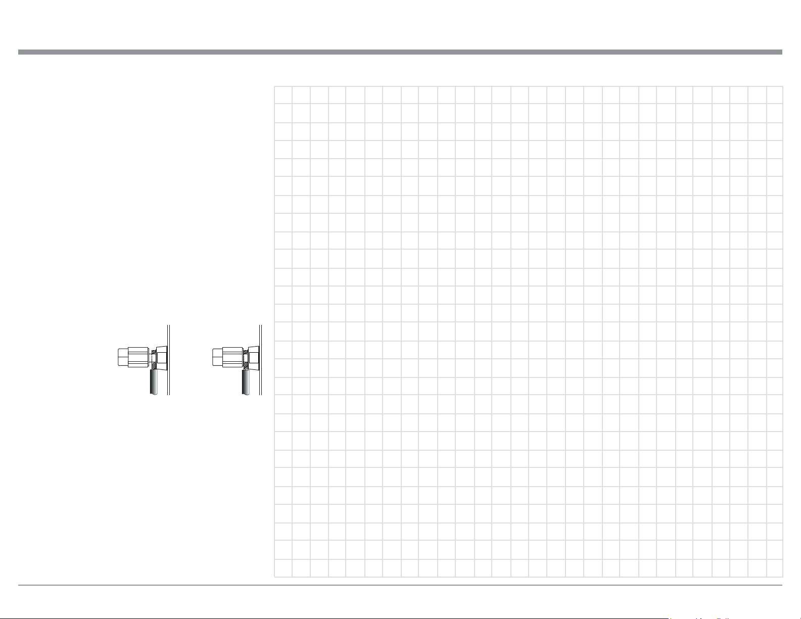
Spade Lug or Wire Connections:
6. Connect the Loudspeaker hookup cables to the
MA/MAC6700 Negative Output Terminal and
Positive Output Terminal indentified as 2Ω
(ohms), 4Ω (ohms) or 8Ω (ohms) connection to
match the impedance of the Loudspeaker, being
careful to observe the correct polarities. Insert
the spade lug connector or prepared section of the
cable end into the terminal side access hole, and
tighten the terminal cap until the cable is firmly
clamped into the terminals so the lugs or wire cannot slip out. Refer to fgures L and M.
Note: The illustration located on the separate folded
sheet “Mc2B” is for connection to an 8Ω
(ohms) Loudspeaker.
Connecting Loudspeakers
Figure L
Figure M
If the Loudspeaker’s impedance is in-between the
available connections, use the nearest lower impedance connection. Refer to “General Information” Note 7 on page 4 for additional information.
WARNING: Loudspeaker terminals are hazard-
ous live and present a risk of electric
shock. For additional instruction on
making Loudspeaker Connections contact your McIntosh Dealer or McIntosh Technical Support.
7. Connect the MA/MAC6700 power cord to an active AC outlet.
15
 Loading...