

McIntosh MA-6200 Owners manual
THE MA
6200
INTEGRATED AMPLIFIER
Reading Time: 40 Minutes
Price: $2.00

VARIOUS REGULATORY AGENCIES REQUIRE THAT WE BRING THE FOLLOWING INFORMATION TO YOUR ATTENTION. PLEASE READ IT CAREFULLY.
WARNING: TO PREVENT FIRE OR SHOCK
HAZARD, DO NOT EXPOSE THIS UNIT TO
RAIN OR MOISTURE.
The Mclntosh you have purchased is a Model MA
6200. It has a serial number located on the rear panel
of the chassis. Record that serial number here:
Serial Number
The model, serial number and purchase date are
important to you for any future service. Record the
purchase date here:
Purchase Date
Upon application, Mclntosh Laboratory provides a
Three-Year Service Contract. Your Mclntosh
authorized Service Agency can expedite repairs
when you provide the Service Contract with the instrument for repair. To assist, record your Service
Contract number here:
Service Contract Number

Your MA 6200 Integrated Amplifier
will give you many years of pleasant and
satisfactory performance. If you
have any questions, please contact:
CUSTOMER SERVICE
Mclntosh Laboratory Inc.
2 Chambers Street
Binghamton, New York 13903-9990
Phone: 607-723-3512
Take Advantage of 3 years
of Contract Service ...
Fill in the Application NOW.
MclNTOSH THREE YEAR SERVICE CONTRACT
An application for A THREE YEAR SERVICE CONTRACT is included with this manual.
Contents
HOW TO INSTALL... 2
HOW TO CONNECT... 4
THE FRONT PANEL CONTROLS
AND HOW TO USE THEM... 8
PERFORMANCE LIMITS . . .12
PERFORMANCE CHARTS . . .13,14
TECHNICAL DESCRIPTION .. .15
BLOCK DIAGRAM...17
The terms of the contract are:
1. Mclntosh will provide all parts, materials
and labor needed to return the measured
performance of the instrument to the
original performance limits. The SERVICE CONTRACT does not cover any
shipping costs to and from the authorized service agency or the factory.
2. Any Mclntosh authorized service agency
will repair Mclntosh instruments at nor-
mal service rates. To receive service
under the terms of the SERVICE CON-
TRACT, the SERVICE CONTRACT CER-
TIFICATE must be presented when the
instrument is taken to the service agency.
3. Always have service done by a Mclntosh
authorized service agency. If the instru-
ment is modified or damaged as a result
of unauthorized repair, the SERVICE
CONTRACT will be cancelled. Damage
by improper use or mishandling is not
covered by the SERVICE CONTRACT.
4. The SERVICE CONTRACT is issued to
you as the original purchaser. To protect
you from misrepresentation, this contract cannot be transferred to a second
owner.
5. To receive the SERVICE CONTRACT,
your purchase must be made from a
Mclntosh franchised dealer.
6. Your completely filled in application for
SERVICE CONTRACT must be postmarked within 30 days of the date of purchase
of the instrument.
7. To receive the SERVICE CONTRACT, all
information on the application must be
filled in. The SERVICE CONTRACT will
be issued when the completely filled in
application is received by Mclntosh
Laboratory Inc. in Binghamton, New York.
Copyright 1979 © by Mclntosh Laboratory Inc.
1
The PANLOC system of installing equipment con-
veniently and securely is a product of Mclntosh
research. By depressing the two PANLOC buttons
on the front panel, the instrument slide can be locked firmly in place or it can be unlocked so that the
chassis can slide forward, giving you easy access to
the top and rear panels.
The trouble-free life of an electronic instrument is
greatly extended by providing sufficient ventilation
to prevent the buildup of high internal temperatures
that cause deterioration. Allow enough clearance so
that cool air can enter at the bottom of the cabinet
and be vented from the top. With adequate ventilation the instrument can be mounted in any position.
The recommended minimum space for installation
is 15 inches (38.1 cm) deep, 17 inches (43.2 cm) wide,
and 6 inches (15.2 cm) high.
To install the instrument in a Mclntosh cabinet,
follow the instructions that are enclosed with the
cabinet. For any other type of installation follow
these instructions:
1. Open the carton and remove the PANLOC
brackets, hardware package, and mounting
template from the carton. Remove the MA 6200 from
its plastic bag and place it upside down on the shipping pallet; unscrew the four plastic feet from the
bottom of the chassis.
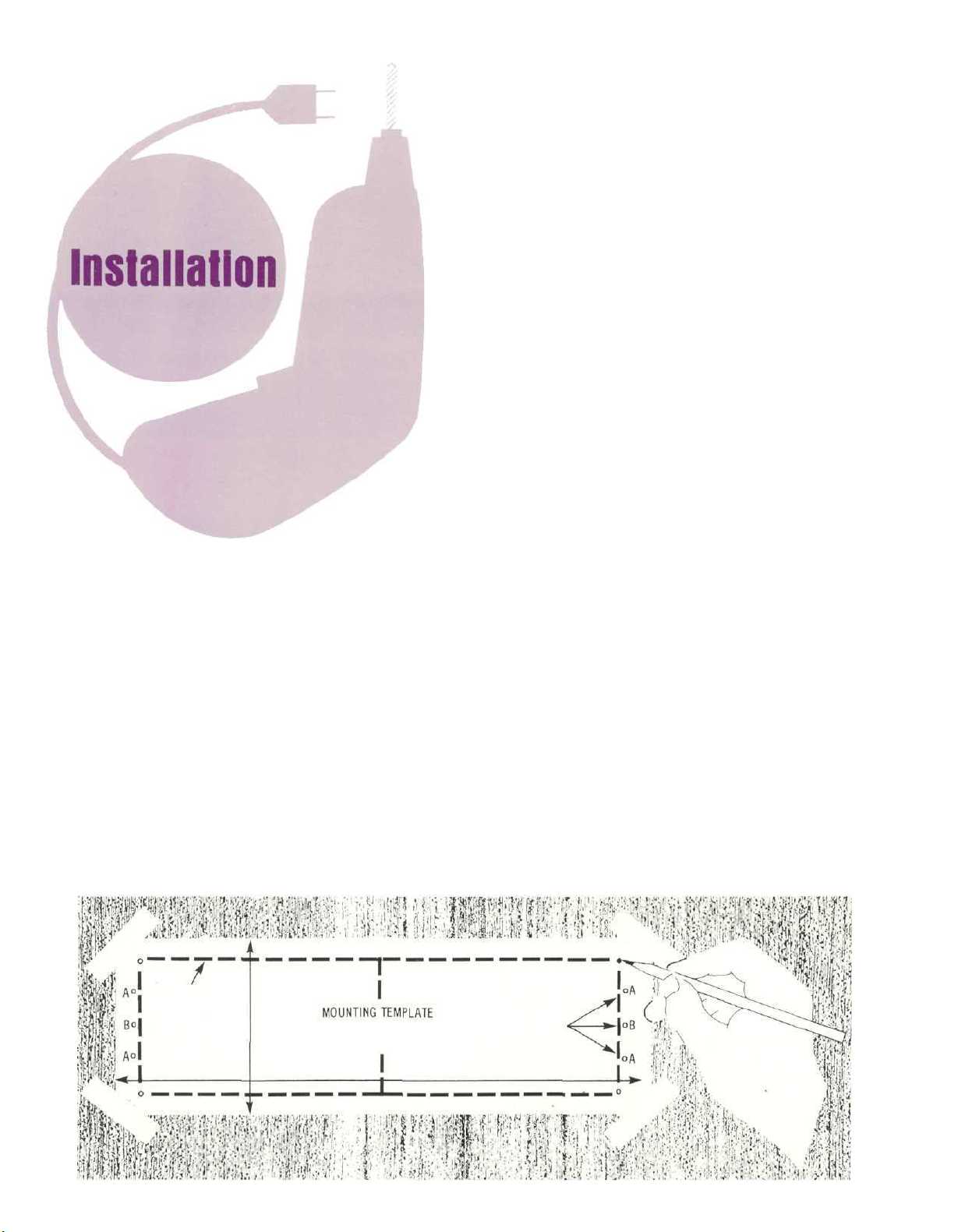
2. Mark the cabinet panel.
Place the mounting template in the position on the
cabinet panel where the instrument is to be installed, and tape it in place. The broken lines that represent the outline of the rectangular cutout also represent the outside dimensions of the chassis. Make
sure these lines clear shelves, partitions, or any
equipment. With the template in place, first mark the
six A and B holes and the four small holes that
locate the corners of the cutout. Then, join the four
corner markings with pencil lines, using the edge of
the template as a straightedge.
3. Drill Holes
Use a drill with a 3/16 inch bit held perpendicular to
the panel and drill the six A and B holes. Then, using
a drill bit slightly wider than the tip of your saw
blade, drill one hole at each of two diagonally op-
posite corners. The holes should barely touch the inside edge of the penciled outline. Before taking the
next step, make sure that the six A and B holes have
been drilled.
4. Saw the Panel Cutout
Saw carefully on the inside of the penciled lines.
First make the two long cuts and then the two short
cuts. After the rectangular opening has been cut out,
use a file to square the corners and smooth any ir-
regularities in the cut edges.
2

5. Install Mounting Strips
In the hardware package you will find two mounting
strips and two sets of machine screws. For panels
that are less than ½ inch thick, use the ¾ inch
screws; for panels that are more than ½ inch thick,
use the 1¼ inch screws.
Starting at the right-hand side of the panel, insert
a screw of the proper length into the center hole in
the panel, marked B on the template. On the back of
the panel, align a mounting strip with the holes in
the panel and tighten the screw until the screwhead
is pulled into the wood.
Repeat this procedure to attach the mounting
strip to the left side of the panel.
6. Attach PANLOC Brackets
Using two screws of the proper length in the A holes
on each side, attach the PANLOC brackets to the
cabinet panel; the short flange is mounted against
the front (face) of the cabinet panel. The screws
pass through the PANLOC bracket flange, the
cabinet panel, and then through the mounting strips
previously mounted.
7. Install the Instrument
Guide the AC power cord through the panel opening
to the back of the cabinet; then, slide the instrument
into the opening carefully so that the rails on the
bottom of each side of the chassis engage the
tracks on the mounting brackets. Continue to slide
the instrument into the cabinet until it is stopped by
the adjust position latches. Press the latches inward, this permits the instrument to slide into the
cabinet until its front panel is flush with the cabinet
panel. Depress the PANLOC buttons at the lower left
and right corners of the instrument panel to lock the
unit firmly in the cabinet. Depressing the PANLOC
buttons again will unlock the instrument so that it
can slide forward to the adjust position; if you press
inward on the adjust position latches then you can
remove the instrument from the cabinet.
3

How to Connect
CONNECTING TURNTABLE TO PHONO 1 AND 2
Connect the cable from the "left" channel of the
turntable into the L PHONO 1 INPUT jack. Connect
the "right" channel into the R PHONO 1 INPUT jack.
Connect a second turntable in the same manner
to the PHONO 2 INPUT jacks. Shorting plugs are
shipped in the PHONO 2 INPUT jacks to eliminate
noise if a second turntable is not used. Remove
these shorting plugs when connecting the second
turntable. Keep them for possible future use. DO
NOT plug the shorting plugs into an output jack as
this may prevent operation of the MA 6200.
GROUND CONNECTION
A single ground post is provided. Grounds for turntables, record changers, tape decks, etc. are to be
connected to this post. The left and right program
cables and the ground wire from that source should
be wound or twisted together. To avoid hum make
sure the ground wire does not make any connections to the shields of the left and right program
cables between the program source and the MA
6200.
CONNECTING A STEREO TUNER AND AUX 1 AND 2
Connect the cable from the "left" channel tuner
output to the L TUNER INPUT jack.
Connect the cable from the "right" channel tuner
output to the R TUNER INPUT jack
AUX—Any high level program source such as a
tuner, a TV set or a tape recorder can be connected
to the AUX 1 and 2 INPUT jacks. The connecting procedure is the same as for the tuner input.
CONNECTING TAPE RECORDERS
To Record:
Connect a cable from the L TAPE 1 OUTPUT jack
to the left high level input of the tape recorder. Con-
nect a cable from the R TAPE 1 OUTPUT jack to the
right high level input of the tape recorder.
Connect a second recorder in the same manner to
the TAPE 2 OUTPUT jacks.
To Playback/Monitor:
Connect a cable from the left channel output of a
tape recorder to the L TAPE 1 INPUT jack. Connect a
cable from the right channel output of a tape
recorder to the R TAPE 1 INPUT jack.
Connect a second recorder in the same manner to
the TAPE 2 INPUT jacks.
CONNECTING AC POWER
The MA 6200 AC power cord is to be plugged into
a 120 volt 50/60 Hz wall outlet.
There are two types of AC power outlets on the
back panel of the MA 6200; three black, and two
green.
The green AC power outlets are on at all times.
Plug the AC power cables from the turntable into the
green TURNTABLE power outlets on the rear panel.
The three black outlets are switched on and off
when the amplifier is turned on or off. These are in-
tended for equalizers and other accessories.
The POWER ON pushbutton shares AC power
control, with the AC power switch on a turntable,
through a current detecting switch circuit. On the
rear panel the TURNTABLE AUTO/MANUAL switch
selects the mode of operation.
When the switch is in the AUTO position and a
turntable plugged into one of the green AC power
outlets, the AC power to the receiver and to the
black AC power outlets can be controlled by the
4
 Loading...