


MX-5 1997
1997 Mazda MX-5 Miata
1997 Mazda MX-5 Miata
GENERATOR & REGULATOR 1997 STARTING & CHARGING SYSTEMS Mazda - Generators & Regulators
GENERATOR & REGULATOR 1997 STARTING & CHARGING SYSTEMS Mazda - Generators & Regulators
GENERATOR & REGULATOR
1997 STARTING & CHARGING SYSTEMS Mazda - Generators & Regulators
DESCRIPTION & OPERATION
Generator is a conventional 3-phase, self-rectifying type with 6 diodes (3 positive and 3 negative) that rectify
current. Internal regulator is solid-state type.
ADJUSTMENTS
BELT DEFLECTION
Measure belt deflection in center of longest pulley-to-pulley span. See BELT DEFLECTION
SPECIFICATIONS table. If belt deflection is not as specified, adjust as necessary.
BELT DEFLECTION SPECIFICATIONS
Application
(1)
Deflection - In. (mm)
New Belt 0.22-0.28 (5.5-7.0)
Used Belt 0.24-0.30 (6.0-7.5)
(1)
With 22 lbs. (10 kg) applied to belt.
TROUBLE SHOOTING
NOTE: See TROUBLE SHOOTING article in GENERAL INFORMATION.
TROUBLE SHOOTING PRECAUTIONS
Observe the following precautions when trouble shooting or testing charging system:
Obtain code number and deactivate audio anti-theft system before disconnecting battery (if equipped).
DO NOT reverse battery cable connections. Rectifier will be damaged.
DO NOT use high voltage type testers.
Battery voltage should always exist at generator terminal "B".
DO NOT ground generator terminal "L" while engine is running.
DO NOT start engine with connector disconnected from generator terminals "L" and "S".
DO NOT apply battery voltage to terminal "L".
ON-VEHICLE TESTING
* PLEASE READ FIRST *
1997 Mazda MX-5 Miata
GENERATOR & REGULATOR 1997 STARTING & CHARGING SYSTEMS Mazda - Generators & Regulators
NOTE: Check generator wiring harness connections and drive belt tension. Battery
must be fully charged before testing. Wait at least 30 seconds after starting
engine before measuring system voltage.
CAUTION: Ensure generator terminal "B" does not contact ground.
GENERATOR OUTPUT
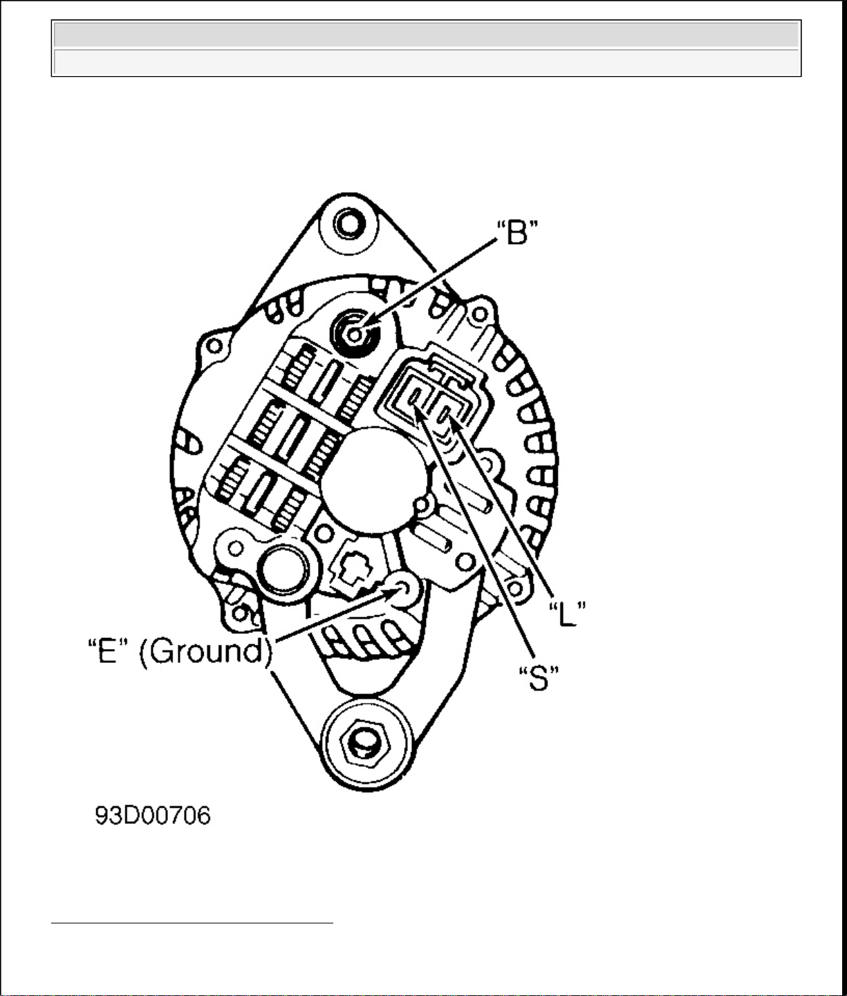
1. Connect an ammeter (100-amp minimum) in-line between generator terminal "B" connector and terminal
"B" of wiring harness connector. See Fig. 1
. Turn headlights and all accessories on. Depress brake pedal.
Operate engine at 2500-3000 RPM.
2. Measure and record generator output. See GENERATOR MAXIMUM RATED OUTPUT table. If
amperage is as specified, go to next step. If amperage is not as specified, repair or replace generator.
3. Turn off headlights and all accessories. Release brake pedal. Operate engine at 2500-3000 RPM and
measure amperage under no-load condition. No-load amperage should be 5 amps or greater. If amperage
is as specified, go to next step. If amperage is not as specified, repair or replace generator.
4. Operate engine at 2500-3000 RPM. Measure voltage between ground and terminals "S" and "L". If 14.1-
14.7 volts does not exist, repair or replace generator. If 14.1-14.7 volts exists, generator output is okay.
GENERATOR MAXIMUM RATED OUTPUT
Application Amps
A/T 70
M/T 65
1997 Mazda MX-5 Miata
GENERATOR & REGULATOR 1997 STARTING & CHARGING SYSTEMS Mazda - Generators & Regulators
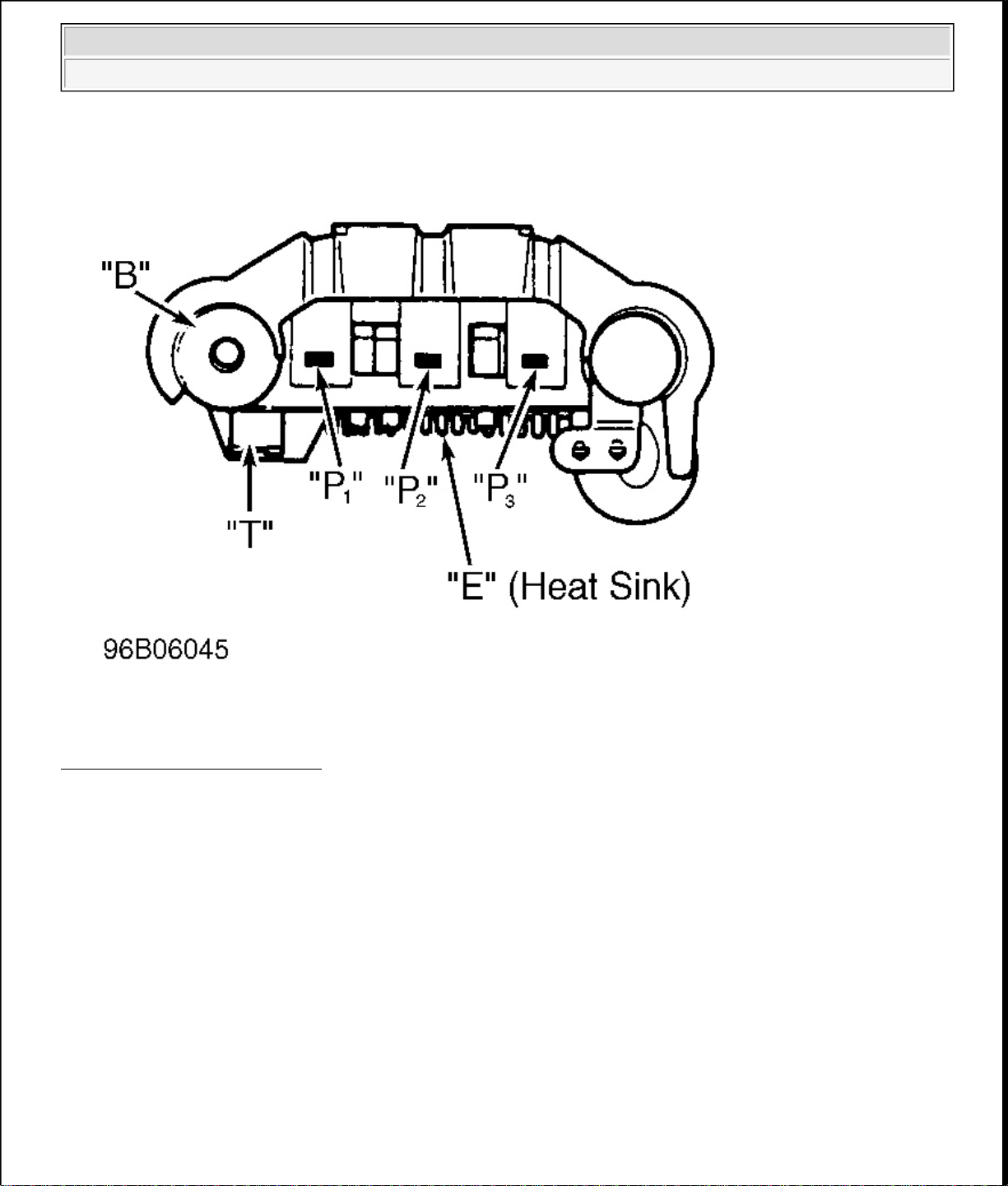
Fig. 1: Identifying Generator Terminals
Courtesy of MAZDA MOTORS CORP.
BENCH TESTING
1997 Mazda MX-5 Miata
GENERATOR & REGULATOR 1997 STARTING & CHARGING SYSTEMS Mazda - Generators & Regulators
RECTIFIER/DIODE ASSEMBLY
1. Using an ohmmeter, check continuity of each diode in both directions (polarity). See Fig. 2 thru Fig. 4 . If
diode shows high resistance in one direction and low resistance in other direction, diode is okay.
2. If diode shows low resistance in both directions, diode is shorted. If diode shows high resistance in both
directions, diode is open. If any diode is defective, replace rectifier assembly.
ROTOR & SLIP RINGS
Measure resistance between rotor slip ring contacts. See Fig. 5 thru Fig. 9 . If resistance is not within
specification, replace rotor. See ROTOR RESISTANCE SPECIFICATIONS table. Check continuity
between individual slip rings and rotor core/shaft. If continuity exists, replace rotor.
ROTOR RESISTANCE SPECIFICATIONS
Application
(1)
Ohms
Miata 3.5-4.5
(1)
If continuity does not exist, replace rotor.
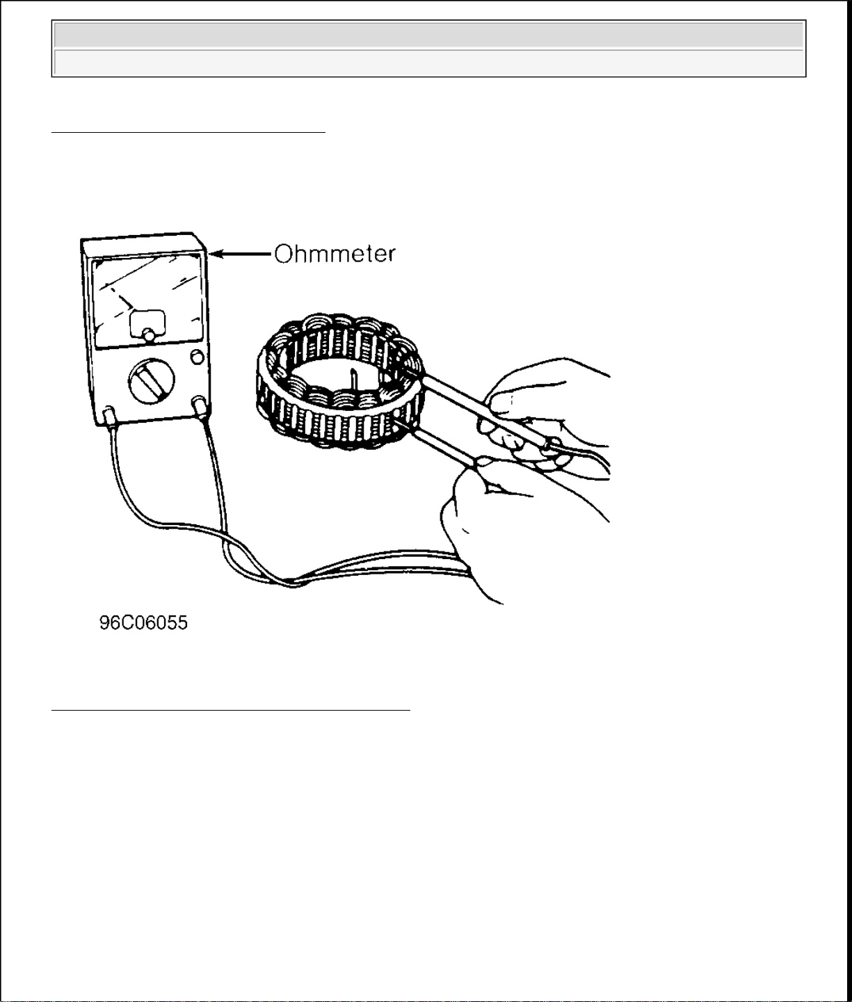
STATOR
Check continuity between stator coil leads and stator core. See Fig. 5 thru Fig. 9 . If continuity exists, replace
stator. Check continuity between leads of stator coil. If continuity does not exist, replace stator.
BRUSHES
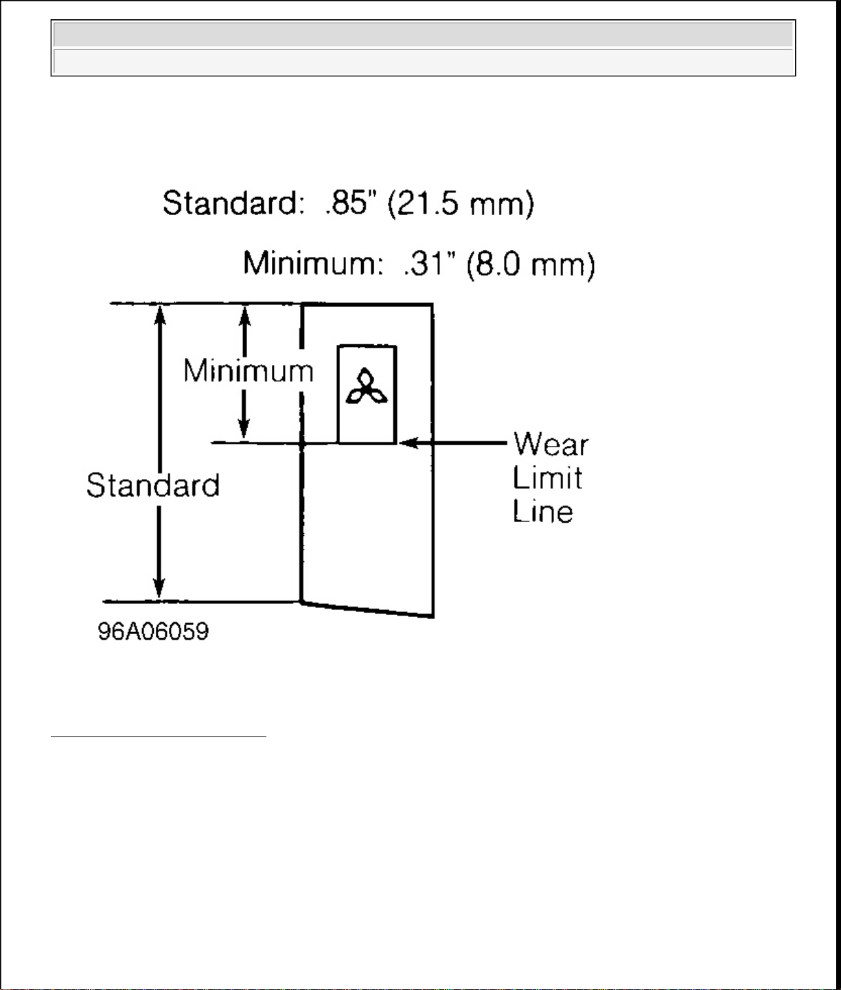
Replace brushes if worn to limit line. See Fig. 5 thru Fig. 9 . Replace brush springs if corroded. For brush
replacement procedure, see OVERHAUL .
1997 Mazda MX-5 Miata
GENERATOR & REGULATOR 1997 STARTING & CHARGING SYSTEMS Mazda - Generators & Regulators
Fig. 2: Testing Rectifier Diodes
Courtesy of MAZDA MOTORS CORP.
1997 Mazda MX-5 Miata
GENERATOR & REGULATOR 1997 STARTING & CHARGING SYSTEMS Mazda - Generators & Regulators
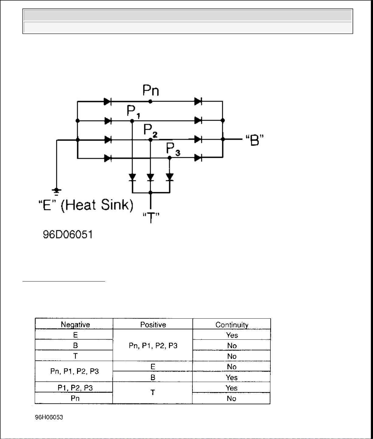
Fig. 3: Rectifier Schematic
Courtesy of MAZDA MOTORS CORP.
1997 Mazda MX-5 Miata
GENERATOR & REGULATOR 1997 STARTING & CHARGING SYSTEMS Mazda - Generators & Regulators
Fig. 4: Rectifier Continuity Test Chart
Courtesy of MAZDA MOTORS CORP.
Fig. 5: Testing Generator Stator, Rotor & Brushes
Courtesy of MAZDA MOTORS CORP.
1997 Mazda MX-5 Miata
GENERATOR & REGULATOR 1997 STARTING & CHARGING SYSTEMS Mazda - Generators & Regulators
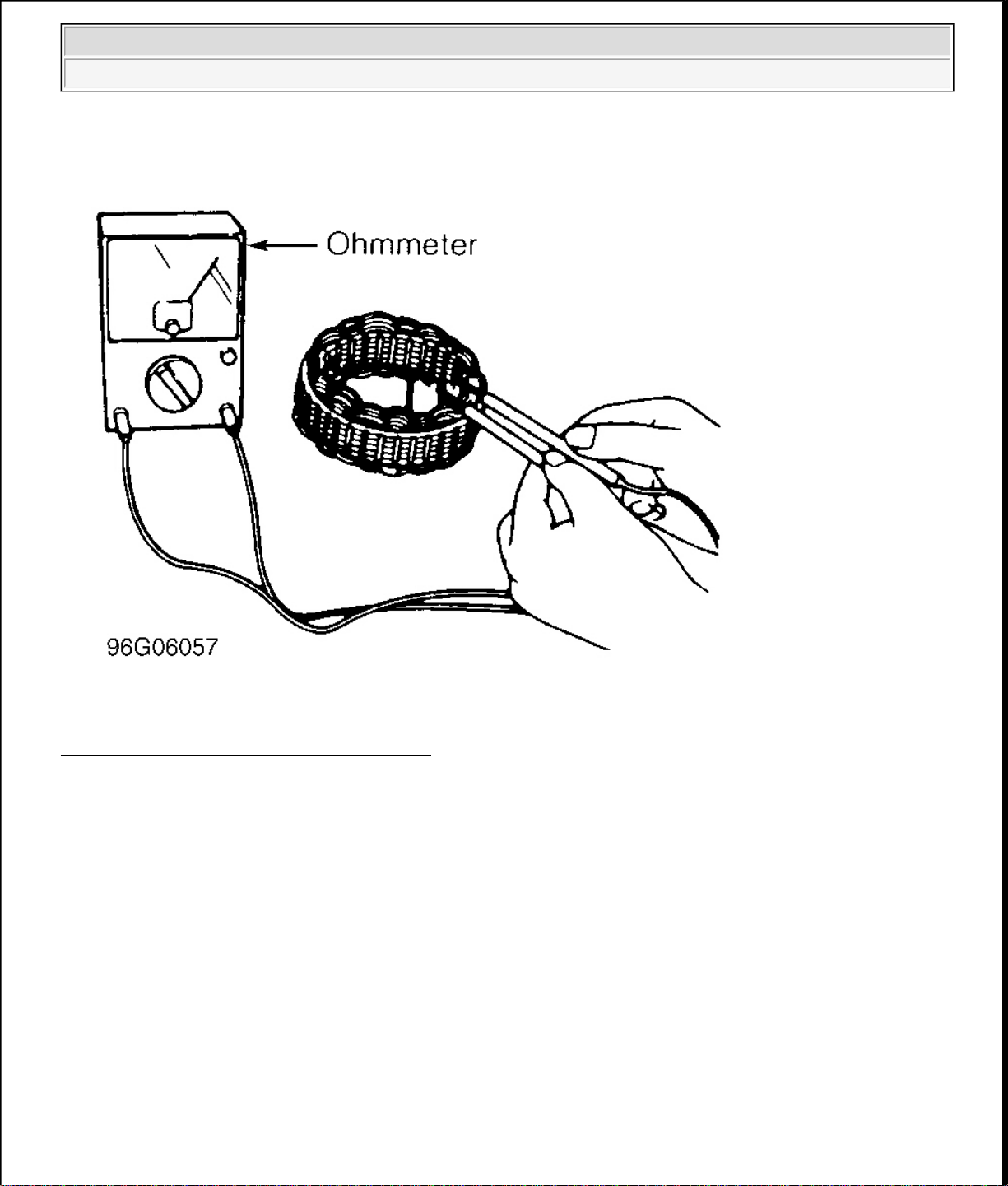
Fig. 6: Checking Stator Winding Continuity
Courtesy of MAZDA MOTORS CORP.
1997 Mazda MX-5 Miata
GENERATOR & REGULATOR 1997 STARTING & CHARGING SYSTEMS Mazda - Generators & Regulators
Fig. 7: Measuring Brush Wear
Courtesy of MAZDA MOTORS CORP.

1997 Mazda MX-5 Miata
GENERATOR & REGULATOR 1997 STARTING & CHARGING SYSTEMS Mazda - Generators & Regulators
Fig. 8: Checking Rotor For Shorts
Courtesy of MAZDA MOTORS CORP.
Fig. 9: Checking Rotor Resistance
Courtesy of MAZDA MOTORS CORP.
1997 Mazda MX-5 Miata
GENERATOR & REGULATOR 1997 STARTING & CHARGING SYSTEMS Mazda - Generators & Regulators
OVERHAUL
DISASSEMBLY
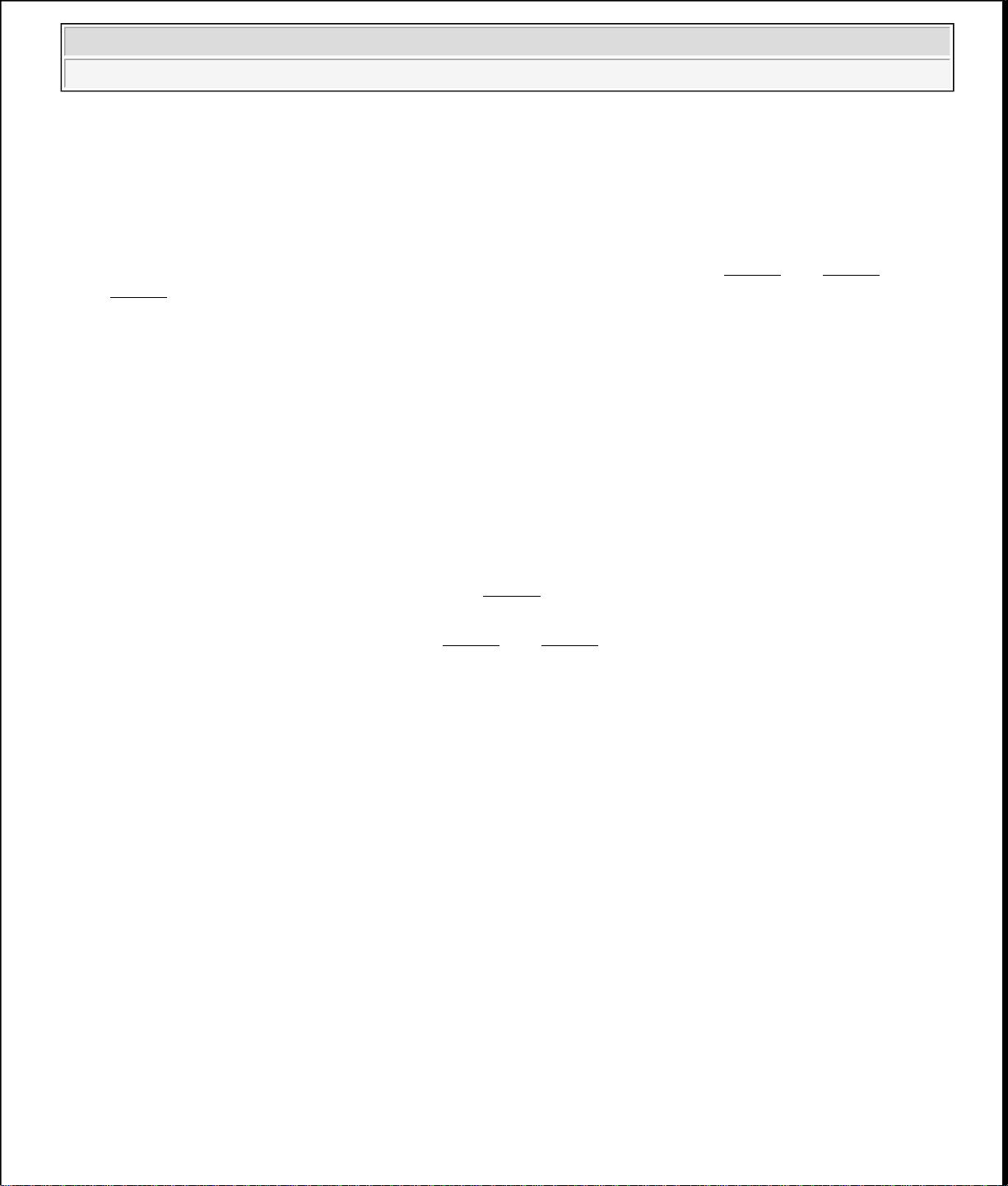
1. Place a 200-watt soldering iron against rear bearing for 3-4 minutes to heat rear cover to 122-140°F (5060°C). Carefully separate front case and rotor from rear cover and stator. See Fig. 10 thru Fig. 15 and
Fig. 17 .
2. Position rotor in vise. Remove pulley. Disassemble pulley, rotor and front case. Remove front bearing
from front case. Using a bearing puller, remove rear bearing.
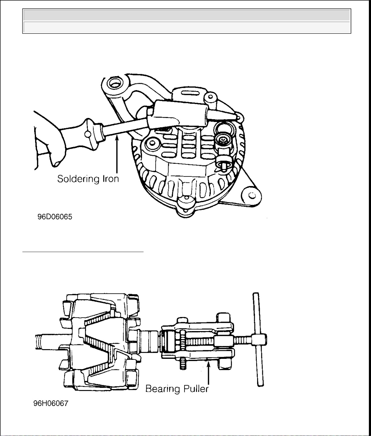
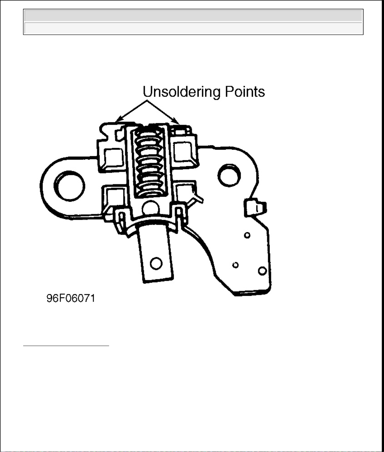
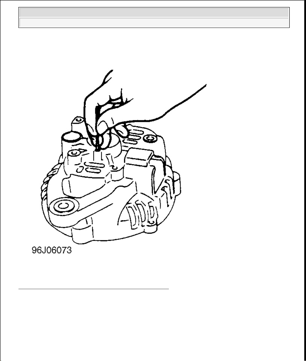
3. Remove "B" terminal nut and bushing from rear cover. Remove screws from brush holder and rectifier.
Separate rear cover and stator. When unsoldering rectifier and stator leads, disconnect as quickly as
possible (5 seconds maximum) to avoid damage to rectifier. To remove brushes from holder, unsolder
pigtail from terminal.
REASSEMBLY
Brush Installation
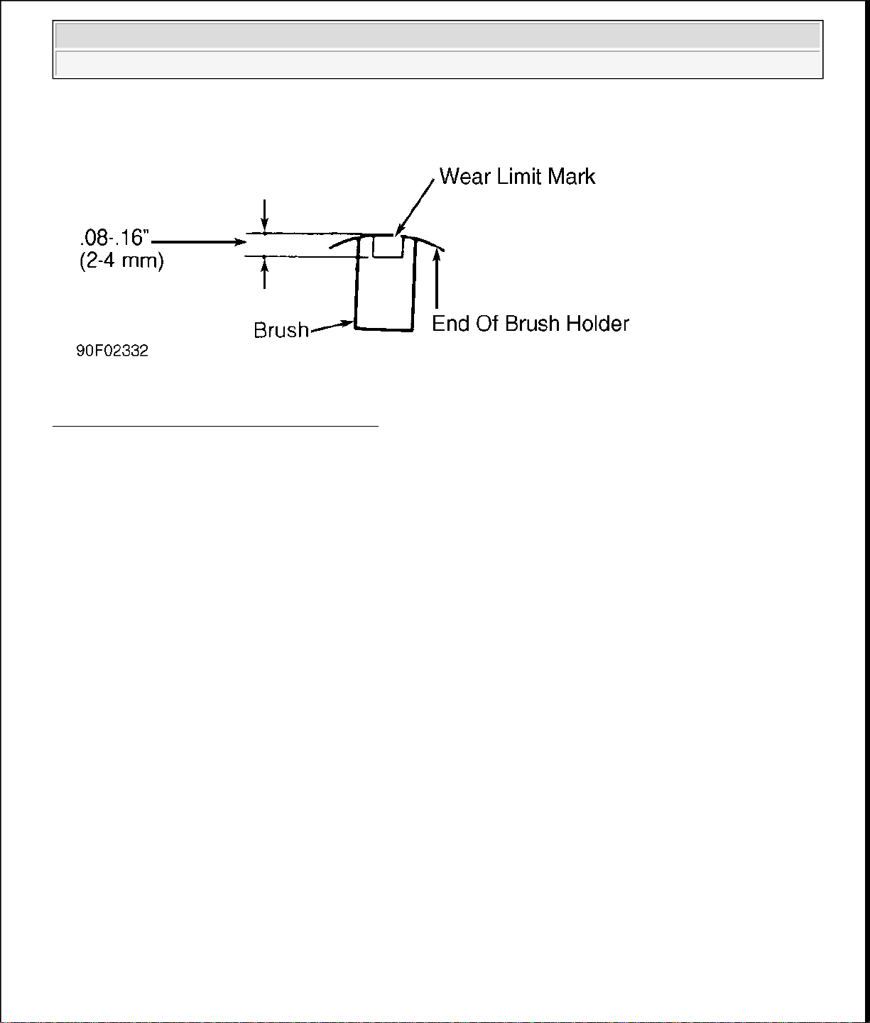
1. Install brush and spring into holder. Allow brush to extend out of holder until wear limit line extends .08.16"(2-4 mm) beyond end of brush holder. See Fig. 16 . Solder pigtail onto brush holder.
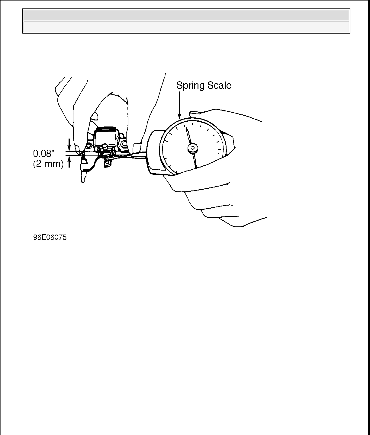
2. Insert spring and brush into brush holder. Using a spring scale, pull brush into holder until end of brush
protrudes .08" (2.0 mm) from holder. See Fig. 10 thru Fig. 15 . Note reading on spring scale. Replace
spring if tension is not 5.6-15.5 ozs. (160-440 g).
1997 Mazda MX-5 Miata
GENERATOR & REGULATOR 1997 STARTING & CHARGING SYSTEMS Mazda - Generators & Regulators
Fig. 10: Heating Rear Bearing Housing
Courtesy of MAZDA MOTORS CORP.
1997 Mazda MX-5 Miata
GENERATOR & REGULATOR 1997 STARTING & CHARGING SYSTEMS Mazda - Generators & Regulators
Fig. 11: Removing Rear Bearing
Courtesy of MAZDA MOTORS CORP.
Fig. 12: Unsoldering Rectifier From Regulator
Courtesy of MAZDA MOTORS CORP.
1997 Mazda MX-5 Miata
GENERATOR & REGULATOR 1997 STARTING & CHARGING SYSTEMS Mazda - Generators & Regulators
Fig. 13: Replacing Brushes
Courtesy of MAZDA MOTORS CORP.
1997 Mazda MX-5 Miata
GENERATOR & REGULATOR 1997 STARTING & CHARGING SYSTEMS Mazda - Generators & Regulators
Fig. 14: Measuring Brush Spring Tension
Courtesy of MAZDA MOTORS CORP.
1997 Mazda MX-5 Miata
GENERATOR & REGULATOR 1997 STARTING & CHARGING SYSTEMS Mazda - Generators & Regulators
Fig. 15: Inserting Wire To Retain Brushes For Reassembly
Courtesy of MAZDA MOTORS CORP.
1997 Mazda MX-5 Miata
GENERATOR & REGULATOR 1997 STARTING & CHARGING SYSTEMS Mazda - Generators & Regulators
Fig. 16: Measuring Installed Depth Of Brush
Courtesy of MAZDA MOTORS CORP.
1997 Mazda MX-5 Miata
GENERATOR & REGULATOR 1997 STARTING & CHARGING SYSTEMS Mazda - Generators & Regulators
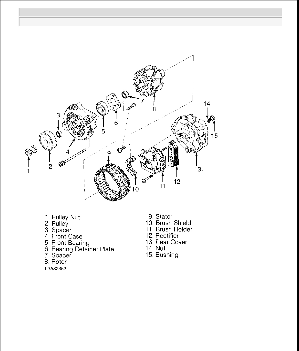
Fig. 17: Exploded View Of Generator
Courtesy of MAZDA MOTORS CORP.
WIRING DIAGRAMS
1997 Mazda MX-5 Miata
GENERATOR & REGULATOR 1997 STARTING & CHARGING SYSTEMS Mazda - Generators & Regulators

1997 Mazda MX-5 Miata
GENERATOR & REGULATOR 1997 STARTING & CHARGING SYSTEMS Mazda - Generators & Regulators
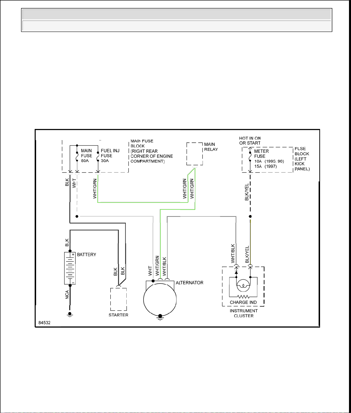
Fig. 18: Charging System Wiring Diagram
1997 Mazda MX-5 Miata
1997 Mazda MX-5 Miata
CLUTCH 1997-98 CLUTCHES Mazda - RWD
CLUTCH 1997-98 CLUTCHES Mazda - RWD
CLUTCH
1997-98 CLUTCHES Mazda - RWD
DESCRIPTION
All models use a hydraulically operated clutch. On all models except Miata, the clutch release bearing and
clutch release cylinder are combined into a single unit. No routine adjustments are necessary on B2300, B2500,
B3000 and B4000 models.
ADJUSTMENTS
CLUTCH PEDAL FREE PLAY
Miata
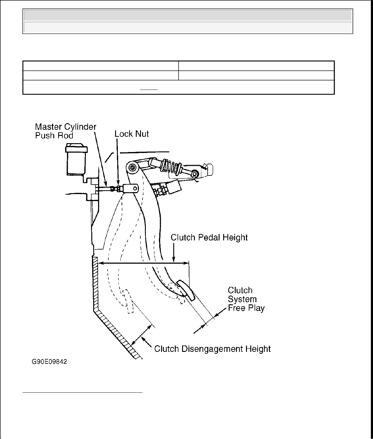
Measure clutch pedal free play. See Fig. 1 . See CLUTCH PEDAL FREE PLAY table. If free play is not
within specification, inspect hydraulic and mechanical system components. If adjustment is required, loosen
lock nut and rotate master cylinder push rod to obtain specified free play. Tighten lock nut.
CLUTCH PEDAL FREE PLAY
(1)
Application In. (mm)
Miata 0.2-0.5 (5-13)
(1)
See Fig. 1 .
CLUTCH PEDAL HEIGHT
Miata
Measure clutch pedal height from bulkhead to front side of pedal pad. See Fig. 1 . See CLUTCH PEDAL
HEIGHT table.
CLUTCH PEDAL HEIGHT
(1)
Application In. (mm)
Miata 6.89-7.28 (175-185)
(1)
Measure to carpet on bulkhead. See Fig. 1 .
CLUTCH DISENGAGEMENT HEIGHT
Miata
Measure clutch disengagement height, where clutch disengages, from pedal pad to bulkhead. See Fig. 1 . See
CLUTCH DISENGAGEMENT HEIGHT (MINIMUM)
table.
1997 Mazda MX-5 Miata
CLUTCH 1997-98 CLUTCHES Mazda - RWD
CLUTCH DISENGAGEMENT HEIGHT (MINIMUM)
(1)
Application In. (mm)
Miata 2.68 (68)
(1)
Measure to carpet on bulkhead. See Fig. 1 .
Fig. 1: Adjusting Clutch Pedal (Miata)
Courtesy of MAZDA MOTORS CORP.
HYDRAULIC SYSTEM BLEEDING
B2300, B2500, B3000 & B4000

1997 Mazda MX-5 Miata
CLUTCH 1997-98 CLUTCHES Mazda - RWD
1. Using Clutch Disconnect Tool (T88T-70522-A), disconnect hydraulic line at transmission. See Fig. 2 .
Clean reservoir cap area. Fill reservoir with DOT 3 brake fluid. Maintain fluid level in reservoir during
bleeding procedure.
2. Using small screwdriver, press and hold internal mechanism of male coupler to open valve. While
holding valve open, have an assistant slowly press and hold clutch pedal to floor.
3. Remove screwdriver to allow valve to close. Release clutch pedal. Refill reservoir.
4. Repeat steps 2) and 3). Install reservoir cap. Reconnect hydraulic line. Tug hydraulic line lightly to verify
secure connection.
5. As rapidly as possible, operate clutch pedal for full 5-10 strokes. Wait 3 minutes. Repeat this step at least
3 more times.
6. Loosen bleed screw, located next to release cylinder connection. Have an assistant press and hold clutch
pedal. Tighten bleed screw. Release pedal. Refill reservoir. Check clutch operation.
Fig. 2: Removing Hydraulic Line (B2300, B2500, B3000 & B4000)
Courtesy of MAZDA MOTORS CORP.
Miata
1. Remove bleeder screw cap located at clutch release cylinder. Install vinyl hose onto bleeder screw.
1997 Mazda MX-5 Miata
CLUTCH 1997-98 CLUTCHES Mazda - RWD
Submerge other end of hose in container of brake fluid.
2. Fill reservoir with DOT 3 brake fluid. Have an assistant press and release clutch pedal several times, then
hold pedal down. With pedal pressed, loosen bleeder screw to let air and fluid escape.
3. Repeat step 2) until no more air bubbles emerge from hose. Tighten bleeder screw. Fill reservoir. Operate
clutch while inspecting for leaks. Check clutch and brake operation.
REMOVAL & INSTALLATION
CLUTCH ASSEMBLY
Removal (B2300, B2500, B3000 & B4000)
1. Disconnect negative battery cable. Shift transmission into Neutral. Remove gearshift lever. Raise and
support vehicle. Mark drive shaft flanges for installation reference. Remove drive shaft. Using Clutch
Disconnect Tool (T88T-70522-A), disconnect hydraulic line at transmission. See Fig. 2 . Plug hydraulic
line to prevent contamination. Disconnect wiring at transmission.
2. Remove starter. Remove exhaust components as necessary for clearance. On 4WD models, remove skid
plate and transfer case. On all models, secure transmission jack under transmission. Remove transmission
mount-to-crossmember nuts and bolts.
3. Remove nuts securing crossmember to frame side rails, and remove crossmember. Lower transmission
enough to gain access to transmission-to-engine block bolts. Remove transmission-to-engine block bolts.
Remove transmission.
4. If clutch parts are going to be reused, mark clutch cover and flywheel for reassembly reference. Loosen
pressure plate bolts evenly in crisscross pattern until springs are not under tension. Remove clutch cover
and clutch disc.
Inspection (B2300, B2500, B3000 & B4000)
1. Inspect disc for loose rivets, worn or defective springs, excessive wear, or oil contamination. Inspect
flywheel and clutch cover for burns, scoring, or grooves.
2. Measure flywheel and clutch cover runout. Resurface or replace flywheel and clutch cover if beyond
specification. See CLUTCH RUNOUT (MAXIMUM) table.
3. Measure clutch disc runout. Replace disc if it is not to specification. See CLUTCH RUNOUT
(MAXIMUM) table. Inspect disc hub and input shaft splines for excessive wear. Hub must slide
smoothly on input shaft splines.
4. Inspect pilot bearing for wear. Apply inward pressure while rotating pilot bearing. If bearing sticks or has
excessive resistance, replace bearing. Check for tight fit in crankshaft. Replace as necessary. Inspect
release bearing for smooth operation, wear, damage, or looseness. Replace bearing as necessary.
CLUTCH RUNOUT (MAXIMUM)
Application In. (mm)
Disc 0.028 (0.7)
Flywheel 0.008 (0.20)
1997 Mazda MX-5 Miata
CLUTCH 1997-98 CLUTCHES Mazda - RWD
Installation (B2300, B2500, B3000 & B4000)
1. Lightly coat input shaft splines, release bearing, and fork contact areas with molybdenum disulfide
grease. Align clutch cover dowel holes with flywheel dowels. Tighten clutch cover bolts evenly in a
crisscross pattern to specification. See TORQUE SPECIFICATIONS
.
2. Raise transmission into position. Install and tighten transmission-to-engine block bolts. See TORQUE
SPECIFICATIONS . Install crossmember.
3. On 4WD models, install NEW transfer case gasket. Install transfer case. Tighten transfer case bolts to
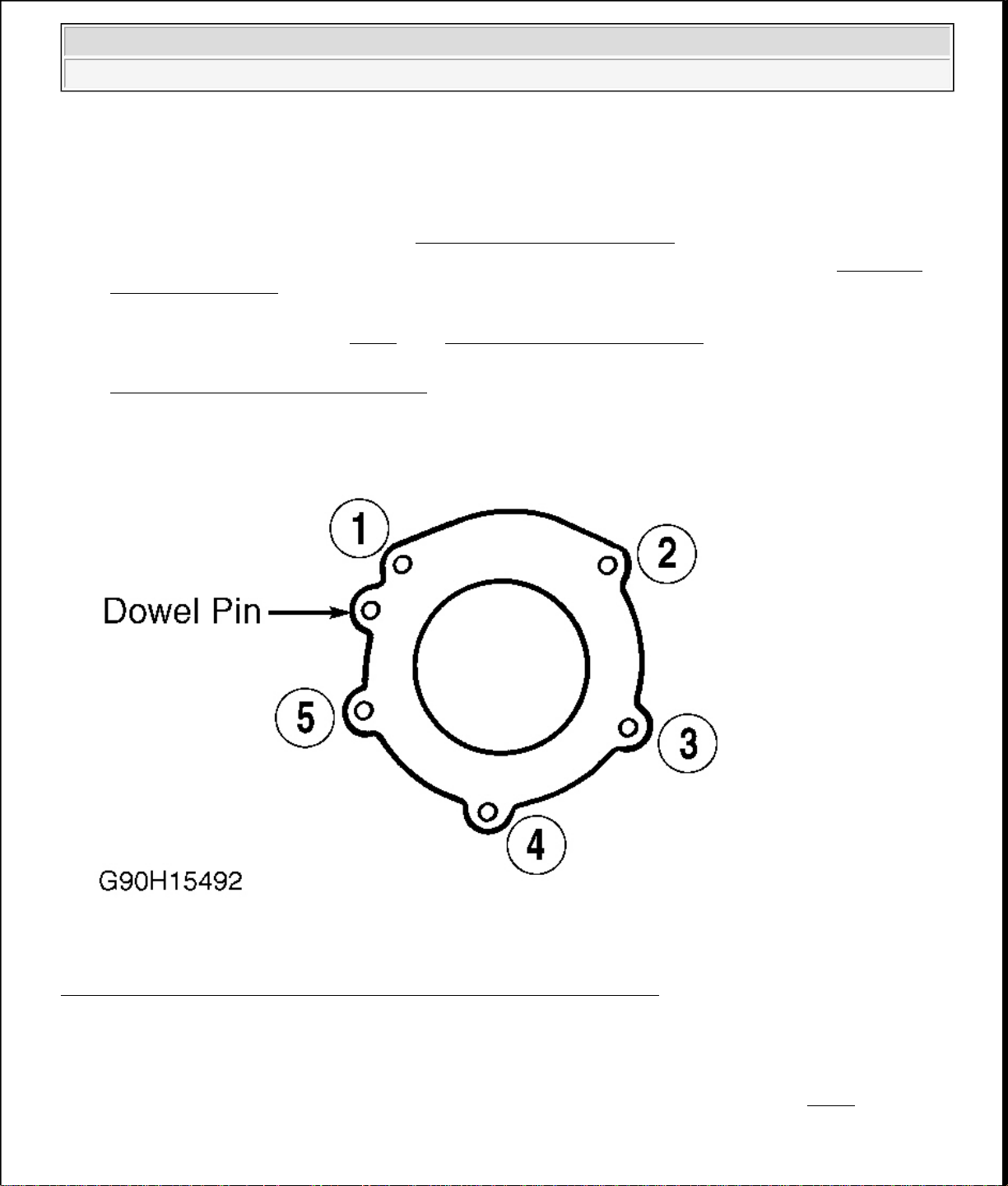
specification is sequence. See Fig. 3 . See TORQUE SPECIFICATIONS .
4. On all models, to complete installation, reverse removal procedure. Bleed hydraulic clutch system. See
HYDRAULIC SYSTEM BLEEDING under ADJUSTMENTS.
Fig. 3: Tightening Transfer Case Bolts (B2300, B2500, B3000 & B4000)
Courtesy of MAZDA MOTORS CORP.
Removal (Miata)
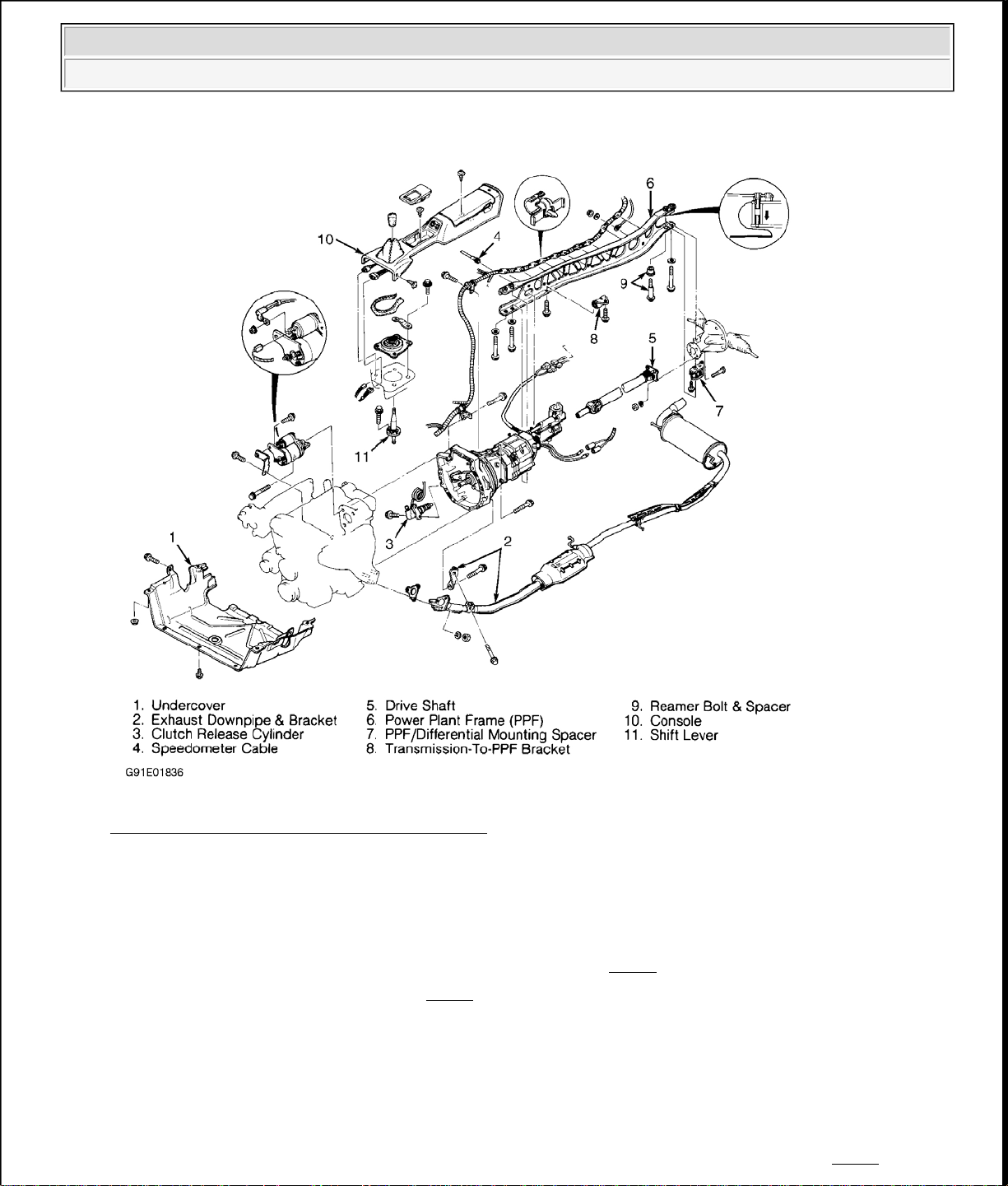
1. Disconnect negative battery cable. Remove gearshift knob, console, and shift lever. See Fig. 4 . Raise and
support vehicle. Remove engine undercover. Disconnect exhaust pipe from manifold. Mark drive shaft
flanges for installation reference. Remove drive shaft.
y
1997 Mazda MX-5 Miata
CLUTCH 1997-98 CLUTCHES Mazda - RWD
Fig. 4: Exploded View Of Drive Line (Miata)
Courtesy of MAZDA MOTORS CORP.
2. Remove clutch release cylinder. Remove starter. Disconnect speedometer cable from transmission. Note
locations, and disconnect wiring harness from Power Plant Frame (PPF).
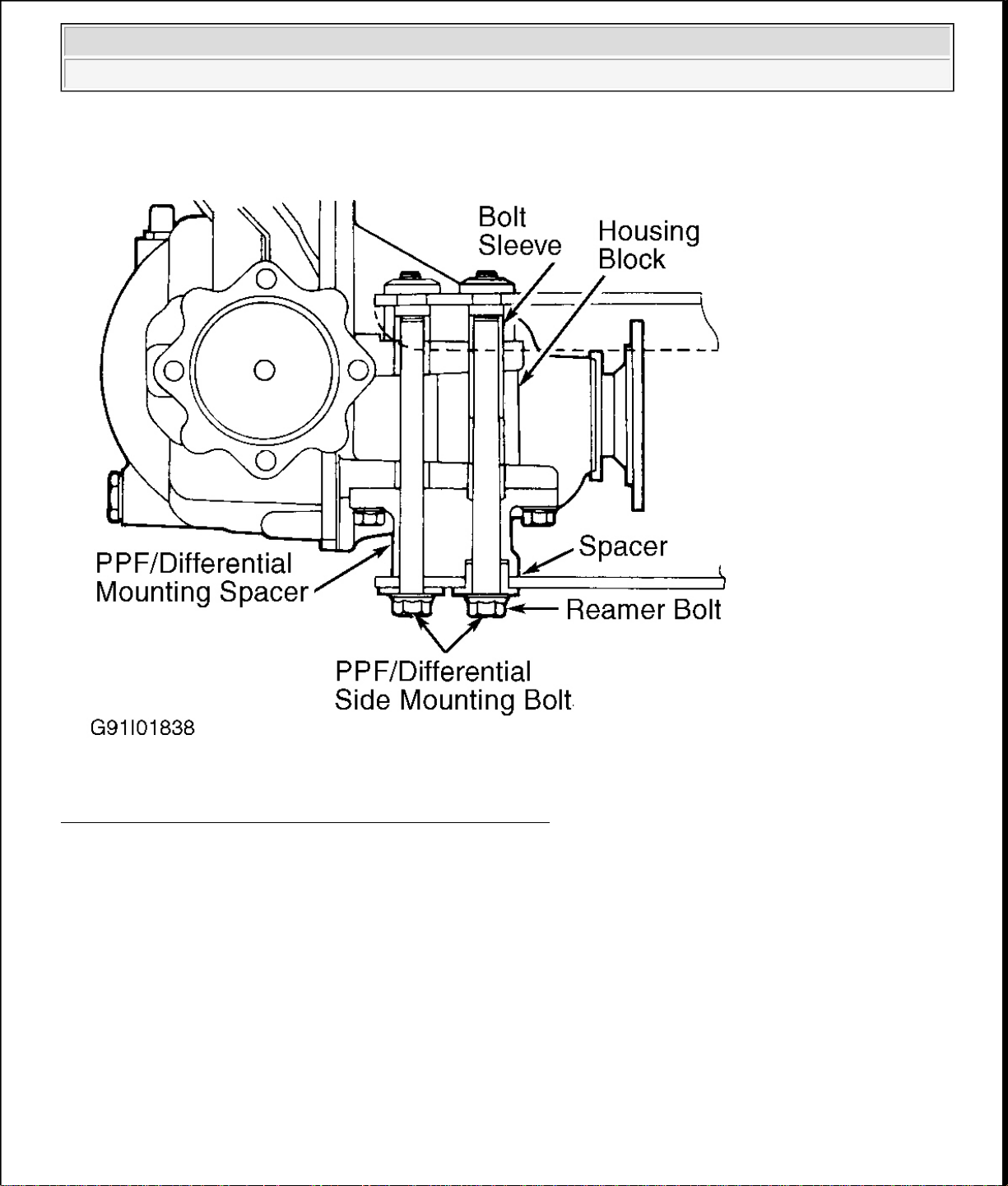
3. Remove PPF bracket from rear transmission extension housing. Remove PPF-to-differential side bolts.
Pry out spacer. Remove PPF/differential mounting spacer. See Fig. 5
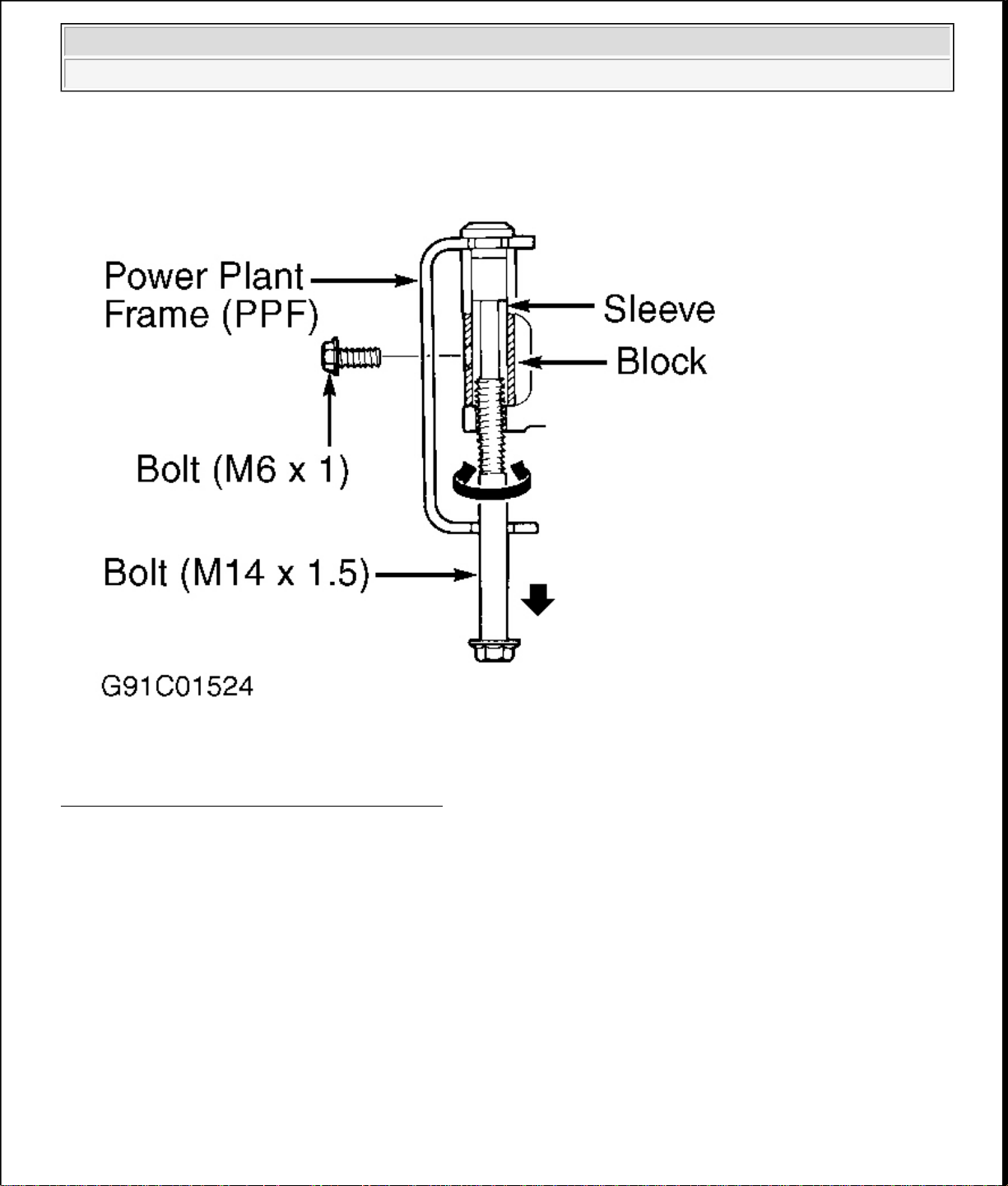
4. Thread M14 X 1.5 bolt into sleeve. See Fig. 6
. Twist bolt side to side while pulling it downward. Thread
.
M6 X 1 bolt into hole in housing block to hold sleeve. Remove long bolt. Remove short bolt.
NOTE: Do not remove spacers attached to top of Power Plant Frame (PPF). If they
are removed, replace PPF.
5. Remove PPF side bolts. Remove PPF. Remove transmission-to-engine block bolts. Remove transmission.
Remove clutch cover bolts evenl
in crisscross pattern. Remove clutch cover and disc. See Fig. 7 .
1997 Mazda MX-5 Miata
CLUTCH 1997-98 CLUTCHES Mazda - RWD
Fig. 5: Installing & Removing Power Plant Frame (Miata)
Courtesy of MAZDA MOTORS CORP.
1997 Mazda MX-5 Miata
CLUTCH 1997-98 CLUTCHES Mazda - RWD
Fig. 6: Removing Reamer Bolt Sleeve (Miata)
Courtesy of MAZDA MOTORS CORP.
1997 Mazda MX-5 Miata
CLUTCH 1997-98 CLUTCHES Mazda - RWD
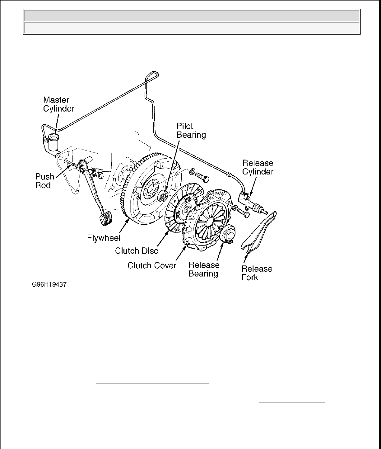
Fig. 7: Exploded View Of Clutch Assembly (Typical)
Courtesy of MAZDA MOTORS CORP.
Inspection (Miata)
1. Inspect disc for loose rivets, worn springs, excessive wear, or oil contamination. Inspect flywheel and
clutch cover for burns, scoring, or grooves.
2. Measure flywheel and clutch cover runout. Resurface or replace flywheel and clutch cover if beyond
specification. See CLUTCH RUNOUT (MAXIMUM)
table. If flywheel ring gear is replaced, ensure
chamfer on flywheel teeth faces engine.
3. Measure clutch disc runout. Replace disc if it is not to specification. See CLUTCH RUNOUT
(MAXIMUM) table. Inspect disc hub and input shaft splines for excessive wear. Hub must slide
smoothly on input shaft splines.
4. Inspect pilot bearing for wear. Apply inward pressure while rotating pilot bearing. If bearing sticks or has
excessive resistance, replace bearing. Check for tight fit in crankshaft. Replace as necessary. Inspect
release bearing for smooth operation, wear, damage, or looseness. Replace bearing as necessary.
1997 Mazda MX-5 Miata
CLUTCH 1997-98 CLUTCHES Mazda - RWD
Installation (Miata)
1. Lightly coat input shaft splines, release bearing, and fork contact areas with molybdenum disulfide
grease. Align clutch cover dowel holes with flywheel dowels. Tighten clutch cover bolts evenly in a
crisscross pattern to specification. See TORQUE SPECIFICATIONS
.
2. Place a wooden block on jack, and position jack under front of oil pan. Raise front of engine to ease
transmission installation. Install transmission. Tighten transmission-to-engine block bolts to specification.
See TORQUE SPECIFICATIONS . Place jack (from front of engine) under transmission.
3. Raise transmission until level with engine. Position Power Plant Frame (PPF) in place. Install
PPF/differential mounting spacer, and tighten bolts to 27-38 ft. lbs. (37-51 N.m). Install and tighten PPF
side mounting bolts.
NOTE: Front PPF-to-differential side mounting bolt is the reamer bolt, used to
align frame.
4. Install sleeve into PPF housing block. Install spacer and bolts. Install reamer bolt into front hole, and
tighten bolt. See Fig. 5 .
5. Install transmission-to-PPF bracket. Install remaining PPF bolts, and tighten to specification. See
TORQUE SPECIFICATIONS . To complete installation, reverse removal procedure.
RELEASE BEARING & FORK
Removal (B2300, B2500, B3000 & B4000)
With transmission removed, twist release bearing and carrier assembly until preload spring pushes bearing
assembly from slave cylinder. See Fig. 8 .
NOTE: Use only lithium base grease on release bearing. DO NOT use petroleum base
lubricants.
Installation
Lubricate bearing bore and bearing carrier with NIGI No. 2 (lithium base) grease. Push release bearing
assembly onto clutch slave cylinder.
 Loading...