


Maytag MEDE301Y, MEDE201Y, MGDB400V, MGDB700V, MGDB800V Product Dimensions
...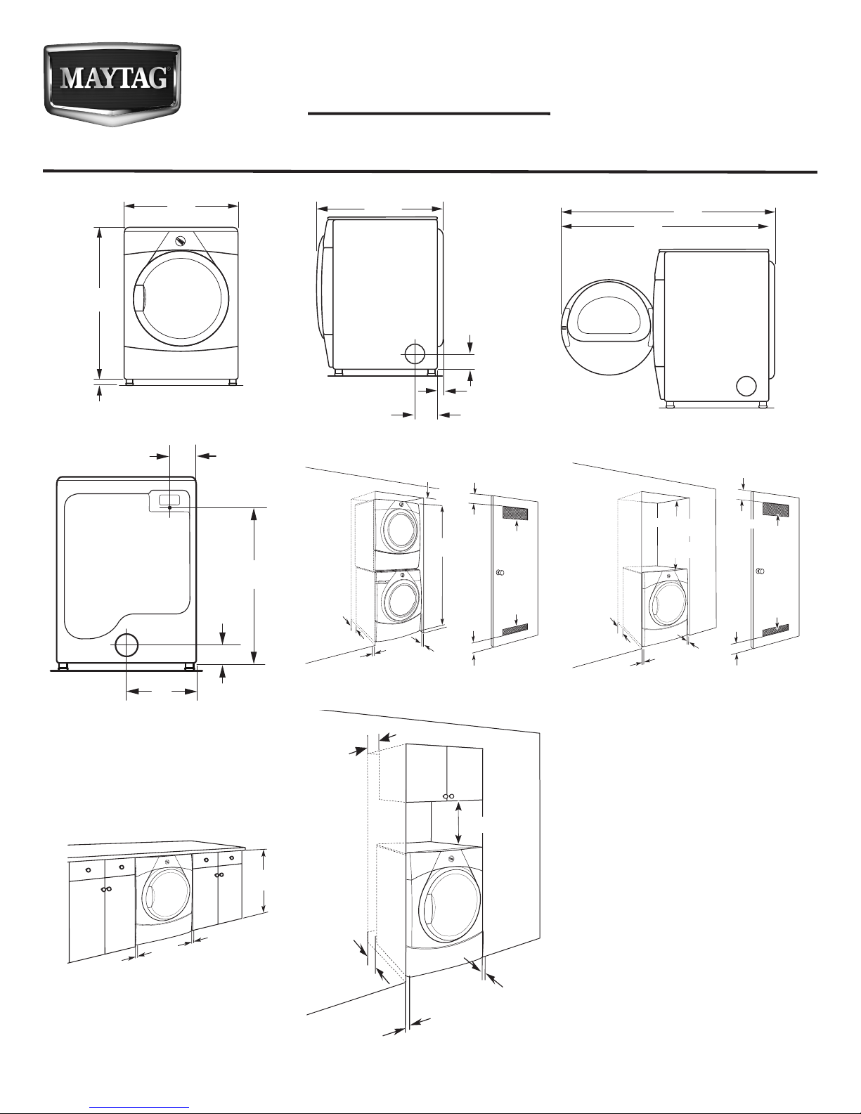
Electric Dryer
27"
29"
PRODUCT MODEL NUMBERS
MEDE200X, MEDE201Y, MEDE250X,
MEDE251Y, MEDE301Y
DRYER DIMENSIONS
Front view:
Back view:
3
/8"
35
(899 mm)
1"
(25 mm)
Electric
(686 mm)
14"
(358 mm)
(159 mm)
3
(89 mm)
1
6
1
/2"
/4"
28
(715 mm)
Side view:
1
/8"
NOTE: Most installations require a minimum
5" (102 mm) clearance behind the dryer for
the exhaust vent with elbow. See “Venting
Requirements”.
Custom under counter installation (dryer only):
39" min.
1"
(25 mm)
(25 mm)
(990 mm)
1"
NOTE: Some models not recommended for
undercounter installation.
Door open view:
(736 mm)
Left or
right side
exhaust
7
6
/8"
(174 mm)
1
/2"
3
(89 mm)
5
1
/8"
(41 mm)
471/8"
(1197 mm)
1
/8"
48
(1238 mm)
Closet Installation (stacked washer and dryer): Closet installation (dryer only):
6"
(152 mm)
71"
(1803 mm)
1
5
/2"
(140 mm)
1"
(25 mm)
1"
(25 mm)
Cabinet installation (dryer only):
3"
(76 mm)
3"
(76 mm)
48 in.
(310 cm2)
24 in.
(155 cm2)
2
2
4"
(102 mm)
Spacing for recessed area or closet
34" recommended
(864 mm)
18" min.
(457 mm)
1"
(25 mm)
1"
(25 mm)
(76 mm)
3"
(76 mm)
installation
All dimensions show recommended spacing
7"
(178 mm)
allowed, with tested spacing of 0" (0 mm)
clearance on sides and rear.
■ Additional spacing should be considered
for ease of installation and servicing.
18"
(460 mm)
■ Additional clearances might be required
for wall, door, and oor moldings.
■ Additional spacing should be considered
on all sides of the dryer to reduce noise
transfer.
■ For closet installation, with a door,
minimum ventilation openings in the top
and bottom of the door are required.
Louvered doors with equivalent
4"
(102 mm)
ventilitation openings are acceptable.
■ Companion appliance spacing should
also be considered.
■ No other fuel-burning appliance may be
installed in the same
closet as the dryer.
1"
(25 mm)
1"
(25 mm)
3"
48 in.
(310 cm2)
24 in.
(155 cm2)
2
2
W10443041B
05/2012
INSTALLATION REQUIREMENTS
ELECTRICAL REQUIREMENTS
To supply the required 3 or 4 wire, single phase, 120/240 volt, 60 Hz, AC only electrical supply (or 3 or 4 wire, 120/208 volt electrical
supply, if specied on the serial/rating plate) on a separate 30-amp circuit, fused on both sides of the line. Connect to an individual
branch circuit. Do not have a fuse in the neutral or grounding circuit
WATER (STEAM MODELS ONLY) REQUIREMENTS
The dryer must be connected to the cold water faucet using new inlet hoses. Do not use old hoses. Do not overtighten.
Damage to the coupling can result.
VENTING REQUIREMENTS
Exhaust venting: Exhaust your dryer to the outside. 4" (102 mm)
diameter vent is required. Rigid or exible metal exhaust vent
must be used. Do not use plastic or metal foil vet. Exhaust hood
must be at least 12" (305 mm) from the ground or any object that
may be in the path of the exhaust.
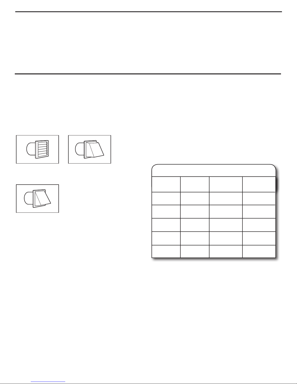
Exhaust hoods:
Recommended Styles:
Louvered Hood
Acceptable Style:
Angled Hood
Box Hood
Determine vent length and elbows needed for best
drying performance:
■ Use following Vent System Chart to determine type of vent
material and hood combinations acceptable to use.
NOTE: Do not use vent runs longer than those specied
in Vent System Chart. Exhaust systems longer than those
specied will:
■ Shorten life of dryer.
■ Reduce performance, resulting in longer drying times
and increased energy usage.
The “Vent System Charts” provide venting requirements that
will help achieve best drying performance.
Standard Vent System Chart
Number of
90° elbows
0
1
Type
of vent
Rigid metal
Rigid metal
Box/louvered
hoods
64 ft. (20 m)
54 ft. (16.5 m)
Angled
hoods
58 ft. (17.7 m)
48 ft. (14.6 m)
Determine vent path:
■ Select route that will provide straightest and most direct
path outdoors.
■ Plan installation to use fewest number of elbows and turns.
■ When using elbows or making turns, allow as much room
as possible.
■ Bend vent gradually to avoid kinking.
■ Use as few 90° turns as possible.
Because Whirlpool Corporation policy includes a continuous commitment to improve Dimensions are for planning purposes only. For complete details, see Installation
our products, we reserve the right to change materials and specications without notice. Instructions packed with product. Specications subject to change without notice.
2
3
4
NOTE: Side and bottom exhaust installations have a 90° turn
inside the dryer. To determine maximum exhaust length, add
one 90° turn to the chart.
Rigid metal
Rigid metal
Rigid metal
44 ft. (13.4 m)
35 ft. (10.7 m)
27 ft. (8.2 m)
38 ft. (11.6 m)
29 ft. (8.8 m)
21 ft. (6.4 m)
 Loading...