


INSTALLATION INSTRUCTIONS
(original instructions)
Commercial Washer
Models MAT20CSAGW, MAT20MNAGW, MAT20PDAGW, and MAT20PNAGW
INSTRUCTIONS D’INSTALLATION
(Instructions d’origine)
Lave-Linge commercial
Modèles MAT20CSAGW, MAT20MNAGW, MAT20PDAGW et MAT20PNAGW
INSTRUCCIONES DE INSTALACIÓN
(Instrucciones originales)
Lavadora Comercial
Modelos MAT20CSAGW, MAT20MNAGW, MAT20PDAGW y MAT20PNAGW
ISTRUZIONI D’INSTALLAZIONE
(Istruzioni originali)
Lavatrice Commerciale
Modellos MAT20CSAGW, MAT20MNAGW, MAT20PDAGW e MAT20PNAGW
W10837717A |
www.maytagcommerciallaundry.com |
|
|
TABLE OF CONTENTS
. |
Page |
Washer Safety.......................................................................... |
3 |
FOR OWNER |
|
General Use Instructions......................................................... |
4 |
Typical Full Load Sizes............................................................ |
4 |
Transporting Your Washer....................................................... |
5 |
If You Need Assistance or Service......................................... |
5 |
FOR MAYTAG AUTHORIZED SERVICE PERSON |
|
Tools & Parts............................................................................. |
6 |
Alternate Parts & Accessories................................................ |
6 |
Dimensions............................................................................... |
7 |
Location Requirements........................................................... |
8 |
Installation Instructions........................................................... |
9 |
Level Washer.......................................................................... |
10 |
Connect Drain Hose............................................................... |
11 |
Drain System.......................................................................... |
12 |
Connect Inlet Hoses.............................................................. |
13 |
Electrical Requirements........................................................ |
14 |
Complete Installation............................................................. |
15 |
Installing Coin Slide and Coin Box....................................... |
15 |
Electronic Controls Set-Up Instructions |
|
(PD & PN Models)................................................................... |
16 |
Washer Disposal.................................................................... |
20 |
Warranty.................................................................................. |
21 |
MODEL NOMENCLATURE:
MAT – Maytag |
MN – Timer Non-Pay |
20 – Model Type Number |
PD – Coin Drop |
CS – Coin Slide |
PN – Electronic Non-Pay |
|
|
ÍNDICE
. |
|
|
Página |
Seguridad de la lavadora........................................................ |
|
42 |
|
PARA EL PROPIETARIO |
|
|
|
Instrucciones del uso general................................................ |
|
43 |
|
Tamaños de cargas típicas de volumen completo.............. |
43 |
||
Transporte de la lavadora....................................................... |
|
44 |
|
Si necesita asistencia o servicio........................................... |
|
44 |
|
PARA EL PERSONAL DE SERVICIO AUTORIZADO |
|||
DE MAYTAG |
|
|
|
Herramientas y piezas............................................................ |
|
45 |
|
Piezas y accesorios alternativos........................................... |
|
45 |
|
Dimensiones............................................................................ |
|
46 |
|
Requisitos de ubicación......................................................... |
|
47 |
|
Instrucciones de instalación.................................................. |
|
48 |
|
Nivelación de la lavadora....................................................... |
|
49 |
|
Conexión de la manguera de desagüe................................. |
50 |
||
Sistema de desagüe............................................................... |
|
51 |
|
Conexión de las mangueras de entrada............................... |
52 |
||
Requisitos eléctricos.............................................................. |
|
53 |
|
Complete la instalación ......................................................... |
|
54 |
|
Instalación del tragamonedas y la caja de monedas.......... |
54 |
||
Instrucciones para programar los controles |
|
||
electrónicos (Modelos PD y PN)............................................ |
|
55 |
|
Eliminación de la lavadora..................................................... |
|
60 |
|
Garantía................................................................................... |
|
61 |
|
NOMENCLATURA DEL MODELO: |
|
||
|
|
|
|
MAT – Maytag |
|
MN – Temporizador |
|
20 – Número de tipo de |
|
operado sin monedas |
|
modelo |
|
PD – Depósito de monedas |
|
CS – Tragamonedas |
|
PN – Operado sin monedas |
|
|
|
electrónico |
|
TABLE DES MATIÈRES
|
|
|
Page |
|
Sécurité du lave-linge............................................................ |
|
22 |
||
POUR LE PROPRIÉTAIRE |
|
|
||
Instructions de l’utilisation général...................................... |
23 |
|||
Taille typique des charges complètes.................................. |
23 |
|||
Transport du lave-linge.......................................................... |
|
24 |
||
Si vous avez besoin d’assistance ou service...................... |
24 |
|||
POUR LE PERSONNEL D’ENTRETIEN AUTORISÉ |
||||
PAR MAYTAG |
|
|
|
|
Outillage et pièces................................................................. |
|
25 |
||
Pièces supplémentaires et accessoires.............................. |
25 |
|||
Dimensions............................................................................. |
|
26 |
||
Exigences d’emplacement.................................................... |
|
27 |
||
Instructions d’installation...................................................... |
|
28 |
||
Établissement de l’aplomb du lave-linge............................. |
29 |
|||
Raccordement du tuyau de vidange.................................... |
30 |
|||
Système de vidange............................................................... |
|
31 |
||
Raccordement des tuyaux d’arrivée d’eau.......................... |
32 |
|||
Spécifications électriques..................................................... |
|
33 |
||
Achever l’installation............................................................. |
|
34 |
||
Installation de la glissière et de la boîte à monnaie............ |
34 |
|||
Instructions de paramétrage des commandes |
|
|
||
électroniques (Modèles PD et PN)........................................ |
35 |
|||
Élimination du lave-linge....................................................... |
|
40 |
||
Garantie.................................................................................. |
|
41 |
||
NOMENCLATURE DES MODÈLES : |
|
|
||
|
|
|
|
|
MAT – Maytag |
|
MN – Minuterie non payant |
||
20 – ## (p. ex. 25) Numéro |
|
PD – Chute de pièce |
|
|
de type du modèle |
|
PN – Non payant électronique |
||
CS – Glissière à pièces |
|
|
|
|
|
|
|
|
|
SOMMARIO |
|
|
|
|
. |
|
|
Pagina |
|
Sicurezza della lavatrice........................................................ |
|
62 |
||
PER IL PROPRIETARIO |
|
|
|
|
Istruzioni del uso generale.................................................... |
|
63 |
||
Dimensioni tipiche a carico completo................................. |
63 |
|||
Transporto della lavatrice...................................................... |
|
64 |
||
Se avete bisogno dell’assistenza o servizio........................ |
64 |
|||
PER IL PERSONALE DI ASSISTENZA |
|
|
||
AUTORIZZATO MAYTAG |
|
|
||
Attrezzi e componenti............................................................ |
|
65 |
||
Parti e accessori alternativi.................................................. |
|
65 |
||
Dimensioni.............................................................................. |
|
66 |
||
Requisiti di posizionamento.................................................. |
|
67 |
||
Istruzioni d’installazione........................................................ |
|
68 |
||
Livellamento della lavatrice.................................................. |
|
69 |
||
Connessione del tubo di scarico.......................................... |
70 |
|||
Sistema di scarico.................................................................. |
|
71 |
||
Collegare i tubi d’ingresso.................................................... |
|
72 |
||
Requisiti elettrici.................................................................... |
|
73 |
||
Completamento dell’installazione........................................ |
74 |
|||
Installazione dello scivolo monete e della gettoniera........ |
74 |
|||
Istruzioni di configurazione dei comandi elettronici |
|
|
||
(Modelli PD e PN)................................................................... |
|
75 |
||
L’eliminazione della lavatrice................................................ |
|
79 |
||
Garanzia.................................................................................. |
|
80 |
||
NOMENCLATURA DI MODELLO: |
|
|
||
|
|
|
|
|
MAT – Maytag |
|
MN – Temporizzatore |
|
|
20 – Numero di Tipo |
|
non a gettoni |
|
|
di modello |
|
PD – Imbuto monete |
|
|
CS – Scivolo gettoni |
|
PN – Non a gettoni |
|
|
|
|
elettroniche |
|
|
2
WASHER SAFETY
NOTE: Washer installation and service must be performed by a Whirlpool authorized service person.
IMPORTANT SAFETY INSTRUCTIONS
WARNING: To reduce the risk of fire, electric shock, or injury to persons when using the washer, follow basic precautions, including the following:
ν Read all instructions before using the |
. |
|
washer. |
||
|
νDo not wash articles that have been previously cleaned in, washed in, soaked in, or spotted with petrol, dry-cleaning solvents, or other flammable or explosive substances as they give off vapours that could ignite or explode.
νDo not add petrol, dry-cleaning solvents, or other flammable or explosive substances to the wash water. These substances give off vapours that could ignite or explode.
νUnder certain conditions, hydrogen gas may be produced in a hot water system that has not been used for 2 weeks or more. HYDROGEN GAS IS EXPLOSIVE. If the hot water system has not been used for such a period, before using the washer, turn on all hot water taps and let the water flow from each for several minutes. This will release any accumulated hydrogen gas. As the gas is flammable, do not smoke or use an open flame during this time.
νThe appliance must be disconnected from its power source during service and when
replacing parts. The power cord plug should be visible at all times once disconnected to verify that power remains removed.
νThis appliance is not intended for use by children or by persons with reduced physical, sensory, or mental capabilities, or lack of experience and knowledge, unless they have been given supervision or instructions concerning safe use of the appliance by persons responsible for their safety. Such persons must also understand the possible hazards involved during use.
νThe appliance can be used by children age 8 years and above and persons with reduced physical, sensory, or mental capabilities, or lack of experience and knowledge if they have been given supervision or instructions concerning safe use of the washer, and if they understand the hazards involved.
νChildren of less than 3 years should be kept away unless continuously supervised.
νThis appliance is intended to be used in household and similar applications such as staff kitchen areas, shops, offices, other working environments, farm houses. It can also be used by clients in hotels, motels, other residential type environments, bed and breakfast type environments, areas for communal use in blocks of flats, or in launderettes.
SAVE THESE INSTRUCTIONS
3

ν No washer can completey remove oil. Do not |
ν Do not install or store the washer where it will be |
|
dry anything that has ever had any type of oil |
exposed to the weather. |
|
on it (including cooking oils). Doing so can result |
ν Do not tamper with controls. |
|
in death, explosion, or fire. |
ν After installation, access to mains plug or |
|
ν It is recommended that fiberglass items not |
||
mains supply via a double-pole switch must |
||
be washed in coin-operated washers. If these |
be maintained at all times in order to ensure |
|
items are washed in the washer, run the washer |
immediate deactivation of the washer in case |
|
through a complete cycle to rinse away any |
of emergency. |
|
residue that might be left in the washer. |
ν Do not repair or replace any part of the washer |
|
ν Cleaning and user maintenance by children must |
||
or attempt any servicing unless specifically |
||
be supervised. |
recommended in this manual. You must also |
|
ν Do not allow children to play on, in, or with |
understand these instructions and have the |
|
the washer. Close supervision of children is |
skills to carry them out. |
|
necessary when the washer is used near children. |
ν See “Electrical Requirements” for grounding |
|
ν Before the washer is removed from service or |
instructions. |
|
discarded, remove the door or lid. |
|
ν Do not reach into the washer if the basket, tub, or agitator is moving.
SAVE THESE INSTRUCTIONS
GENERAL USE INSTRUCTIONS
νWater pressure of 138–690 kPa (20–100 psi) is needed for operation of the washer.
νUse new hoses supplied with the washer. Do not reuse old hoses.
νIf the supply cord is damaged, it must be replaced by the manufacturer, its service agent, or similarly qualified persons in order to avoid a hazard.
TYPICAL FULL LOAD SIZES
Load Type |
Loading Suggestion |
Load Type |
Loading Suggestion |
|
|
|
|
Mixed Load |
3 double sheets |
Heavy Work Clothes |
3 pair pants |
|
4 pillowcases |
|
3 shirts |
|
6 pair shorts |
|
1 coverall |
|
8 T-shirts |
|
4 pair jeans |
|
2 shirts |
|
1 overall |
|
2 blouses |
|
|
|
8 handkerchiefs |
|
|
|
|
|
|
Permanent Press |
2 double or 1 king size sheet |
Knits |
3 blouses |
|
1 tablecloth |
|
4 slacks |
|
1 dress |
|
6 shirts |
|
1 blouse |
|
4 tops |
|
2 slacks |
|
4 dresses |
|
3 shirts |
|
|
|
2 pillowcases |
|
|
|
|
|
|
4

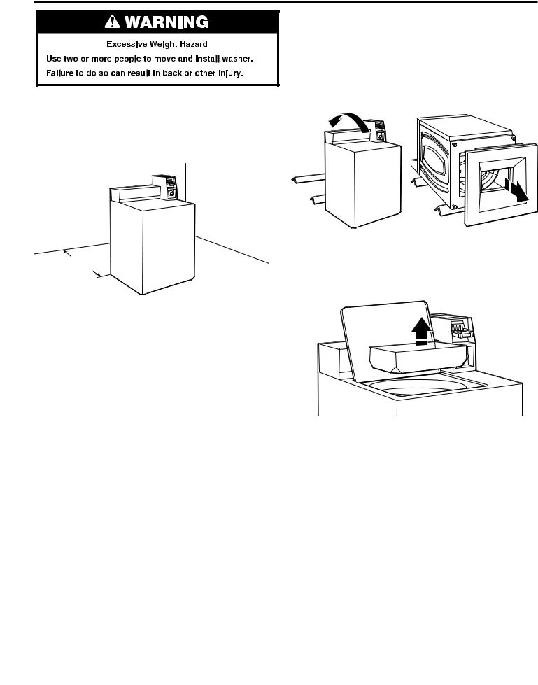
TRANSPORTING YOUR WASHER
νShut off both water faucets. Disconnect and drain water inlet hoses.
νDisconnect drain from drain system and drain any remaining water into a pan or bucket. Disconnect drain hose from back of washer.
νUnplug power cord.
νPlace inlet hoses and drain hose inside washer basket.
νDrape power cord over edge and into washer basket.
νPlace packing tray from original shipping materials back inside washer and reuse shipping base to support the motor and tub. If you do not have original packaging, place heavy blankets
or towels above basket, between the washer top and the tub ring. Close lid and place tape over lip and down the front of the washer. Keep lid taped until washer is moved to new location.
IF YOU NEED ASSISTANCE OR SERVICE
Your installation may require additional parts. To order, please contact your authorised commercial laundry distributor from whom you purchased your washer or an authorised service company.
You will need the washer model number and serial number. Both numbers can be found on the serial-rating plate located on the washer.
IF YOU NEED SERVICE:
Contact your authorized Maytag® Commercial Laundry distributor. To locate your authorized Maytag® Commercial Laundry distributor, visit www.MaytagCommercialLaundry.com.
For written correspondence:
Maytag® Commercial Laundry Service Department
2000 N M 63
Benton Harbor, Michigan 49022-2632 USA
5
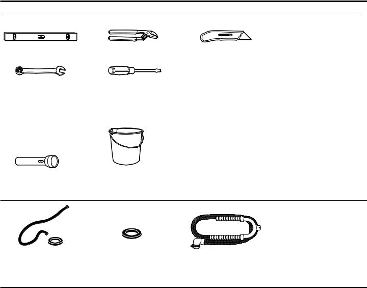
TOOLS & PARTS
Tools Needed:
Level |
Pliers |
Utility Knife |
14 mm (9/16") |
Flat-Blade Screwdriver |
Open-End Wrench |
|
or Adjustable Wrench |
|
Optional tools:
Flashlight |
Bucket |
Parts Supplied:
|
|
|
Drain Hose with Clamp, |
Water Inlet Hoses (2) |
Inlet Hose Washers (4) |
||
|
|
|
U-Form, and Cable Tie |
ALTERNATE PARTS & ACCESSORIES
Your installation may require additional parts. To order, please contact the dealer from whom you purchased your washer or an authorised service company.
If You Have: |
You Will Need: |
|
|
Overhead sewer |
Standard 76 L (20 gal.) 990 mm |
|
(39") tall drain tub or utility sink, |
|
sump pump, and connectors |
|
(available from local plumbing |
|
suppliers) |
25 mm (1") standpipe |
51 mm (2") diameter to |
|
25 mm (1") diameter Standpipe |
|
Adapter Part Number 3363920, |
|
Connector Kit Part Number |
|
285835 |
|
|
Lint clogged drain |
Drain Protector Part Number |
|
367031, Connector Kit Part |
|
Number 285835 |
|
|
Floor drain system |
Siphon Break Part Number |
|
285320, Connector Kit (x2) Part |
|
Number 285835, Extension Drain |
|
Hose Part Number 285863 |
|
|
If You Have: |
|
You Will Need: |
|
|
|
Water faucets beyond |
|
2 longer water fill hoses: |
reach of fill hoses |
|
1.8 m (6 ft.) 90° bend hose |
|
|
Part Number 76314, 3.0 m (10 ft.) |
|
|
Part Number 350008 |
|
|
|
|
|
Inlet hoses are sold as a pair |
|
|
in kit W10575888 |
|
|
|
|
Accessories |
|
|
|
|
If You Have: |
|
You Will Need: |
|
|
|
|
|
Washer Drip Trays |
|
|
Part Number 8212526 |
|
|
|
|
|
Fabric Softener Dispenser Kit |
|
|
Part Number 63594 |
|
|
|
Drain beyond the reach |
|
1.2 m (4 ft.) Drain Hose Extension |
of drain hose |
|
Part Number DRNEXT4 |
|
|
|
6
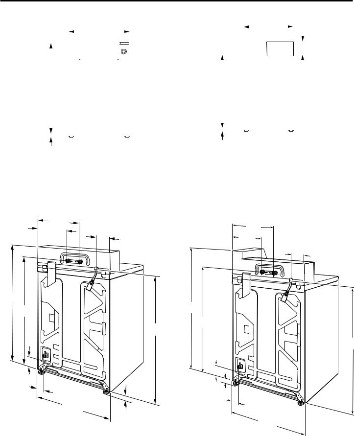
DIMENSIONS
|
|
Front View |
|
|
|
|
|
|
|
Side View |
|
|
|
|
||||||||||||||||||||||
|
|
|
|
|
|
|
|
|
686 mm |
|
|
|
|
|
|
|
|
|
|
|
|
|
|
686 mm |
|
|
|
|
|
|
|
|||||
|
|
|
|
|
|
|
|
|
|
|
|
|
|
|
|
|
|
|
|
|
|
|
|
|
|
|
|
|
|
|||||||
|
|
|
|
|
|
|
|
|
|
|
|
|
|
|
|
|
|
|
|
|
|
|
|
|
|
|
|
|||||||||
|
|
|
|
|
|
(27") |
|
|
|
|
|
|
|
|
(27") |
|
|
|
|
|
|
|
Non-coin-operated |
|||||||||||||
|
|
|
|
|
|
|
|
|
|
|
|
|
|
|
|
|
|
|
|
|
||||||||||||||||
|
|
|
|
|
|
|
|
|
|
|
|
|
|
|
|
|
|
|
|
|
|
|
|
|
|
|
|
|
|
|
|
|
|
|
|
models: |
|
|
|
|
|
|
|
|
|
|
|
|
|
|
|
|
|
|
|
|
|
|
|
|
|
|
|
|
|
|
|
|
|
|
|
|
|
|
|
|
|
|
|
|
|
|
|
|
|
|
|
|
|
|
|
|
|
|
|
|
|
|
|
|
|
|
|
|
|
|
|
|
210 mm159 mm (61⁄4") |
|
|
|
|
|
|
|
|
|
|
|
|
|
|
|
|
|
|
|
|
|
|
|
|
|
|
|
|
|
|
|
|
|
|
||||
|
|
|
|
|
|
|
|
|
|
|
|
|
|
|
|
|
|
|
|
|
|
|
|
|
|
|
|
|
|
|
|
|
( |
81/4" |
||
|
|
|
|
|
|
|
|
|
|
|
|
|
|
|
|
|
|
|
|
|
|
|
|
|
|
|
|
|
|
|
|
|
||||
|
|
|
|
|
|
|
|
|
|
|
|
|
|
|
|
|
|
|
|
|
|
|
|
|
|
|
|
|
|
|
|
|
Coin-operated |
|||
|
|
|
|
|
|
|
|
|
|
|
|
|
|
|
|
|
|
|
|
|
|
|
|
|
|
|
|
|
|
|
|
|
) |
|||
|
|
|
|
|
|
|
|
|
|
|
|
|
|
|
|
|
|
|
|
|
|
|
|
|
|
|
|
|
|
|
|
|
|
|
|
models: |
|
|
|
|
|
|
|
|
|
|
|
|
|
|
|
|
|
|
|
|
|
|
|
|
|
|
|
|
|
|
|
|
|
|
|
|
210 mm (91⁄4") |
|
|
|
|
|
|
|
|
|
|
|
|
|
|
|
|
|
|
|
|
|
|
|
|
|
|
|
|
|
|
|
|
|
|
|
|
|
|
|
|
|
|
|
|
|
|
|
|
|
|
|
|
|
|
|
|
|
|
|
|
|
|
|
|
|
|
|
|
|
|
|
|
|
|
|
|
|
|
|
|
|
|
|
|
|
|
|
|
|
|
|
|
|
|
|
|
|
|
|
|
|
|
|
||||||||
|
|
|
|
|
|
|
|
|
|
|
|
|
|
|
|
|
|
921 mm |
|
|
|
|
|
|
|
|||||||||||
1.080 m |
|
|
|
|
|
|
|
|
|
|
|
|
|
|
|
|
|
|||||||||||||||||||
|
|
|
|
|
|
|
|
|
(361 |
/4") |
|
|
|
|
|
|
|
|
|
|
|
|
|
|
|
|
||||||||||
(421/2") |
|
|
|
|
|
|
|
|
|
|
|
|
|
|
|
|
|
|
|
|
|
|
|
|
|
|
|
|
||||||||
|
|
|
|
|
|
|
|
|
|
|
|
|
|
|
|
|
|
|
|
|
|
|
|
|
|
|
|
|
|
|
|
|
||||
|
|
|
|
|
|
|
|
|
|
|
|
|
|
|
|
|
|
|
|
|
|
|
|
|
|
|
|
|
|
|
|
|
|
|
|
|
|
|
|
|
|
|
|
|
|
|
|
|
|
|
|
|
|
|
|
|
|
|
|
|
|
|
|
|
|
|
|
|
|
|
|
|
|
|
|
|
|
|
|
|
|
|
|
|
|
|
|
|
|
|
|
|
|
|
|
|
|
|
|
|
|
|
|
|
|
|
|
|
|
|
25 mm
25 mm (1")
(1")
|
|
Back View |
|
Non-coin-operated models |
Coin-operated models |
|
406 mm |
406 mm |
267 mm |
(16") |
(16") |
(101/2") |
|
267 mm |
|
140 mm |
(101/2") |
|
(51/2") |
140 mm |
|
|
|
|
|
(51/2") |
1.080 m |
|
|
(421/2") |
1.130 m |
|
946 mm |
||
(441/2") |
||
(371/4") |
946 mm |
|
933 mm |
(371/4") |
|
(363/4") |
|
171 mm (63/4")
171 mm (63/4")
108 mm |
|
25 mm |
|
(41/2") |
|
(1") |
108 mm |
686 mm |
25 mm |
|
(41/4") |
(27") |
|
|
|
|
(1") |
|
686 mm |
|
|
|
|
|
|
|
(27") |
933 mm (363/4")
7
LOCATION REQUIREMENTS
Selecting the proper location for your washer improves performance and minimizes noise and possible washer “walk.”
Your washer can be installed in a basement, laundry room, or recessed area. See “Drain System.”
Companion appliance location requirements should also be considered.
IMPORTANT: Do not install or store the washer where it will be exposed to the weather. Do not store or operate the washer in temperatures at or below 0°C (32°F). Some water can remain in the washer and can cause damage in low temperatures. Proper installation is your responsibility.
You will need:
νA water heater set to 49°C (120°F).
νAn earthed electrical outlet located within 1.2 m (4 ft.) of power cord on back of washer. See “Electrical Requirements.”
νHot and cold water faucets located within 1.2 m (4 ft.) of hot and cold water fill valves on washer, and water pressure
of 138–690 kPa (20–100 psi). A pressure reduction valve should be used in the supply line where inlet pressure entering the building exceeds 690 kPa (100 psi) to avoid damage to the washer mixing valve.
νSingle washer installations require 300 mm (12") minimum risers to provide an air cushion and avoid noise and damage to valves.
νA level floor with maximum slope of 25 mm (1") under entire washer. Installing on carpet is not recommended.
νFloor must support washer’s total weight (with water and load) of 143 kgs (315 lbs).
νA floor drain under the bulkhead. Prefabricated bulkheads with electrical outlets, water inlet lines, and drain facilities should be used only where local codes permit.
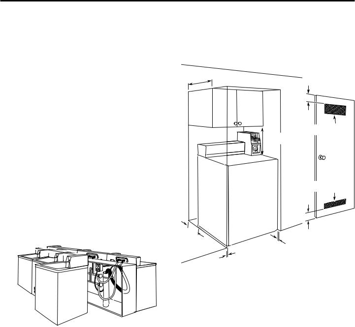
Recessed Area or Closet Installation
This washer may be installed in a recessed area or closet. The installation dimensions shown are the minimum spaces
allowable. Additional spacing should be considered for ease of installation and servicing. Companion appliance spacing should be considered.
Minimum installation spacing
356 mm |
|
(14" max.) |
76 mm |
m |
(3"/3") |
x.) |
|
310 cm2
40657 mm (48 inch2/48 inch2)
(186")
155 cm2
(24 inch2/24 inch2)
m
|
76 mm |
127 mm |
(3"/3") |
|
|
(5") |
25 mm |
|
(1") |
25 mm |
|
(1") |
|
8
INSTALLATION INSTRUCTIONS
It is necessary to remove all shipping materials for proper operation and to avoid excessive noise from washer.
1.Move washer to within 1.2 m (4 ft.) of its final location; it must be in a fully upright position.
NOTE: To avoid floor damage, set washer onto cardboard before moving it and make sure lid is taped shut.
1,2. m
(48")
2.To avoid damaging floor, place cardboard supports from shipping carton on floor behind washer. Tip washer back and place on cardboard supports. Remove shipping base. Set washer upright.
IMPORTANT: Removing shipping base is necessary for proper operation. If your washer includes a sound shield, please refer to the instructions included with the sound shield to install it at this time.
NOTE: Keep shipping base in case you need to move washer later.
3.Remove tape from washer lid, open lid, and remove cardboard packing tray from tub. Be sure to remove all parts from tray.
NOTE: Tray must be removed prior to plugging the washer into an outlet. Keep tray in case you need to move washer later.
9
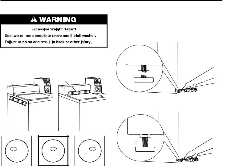
LEVEL WASHER
IMPORTANT: Level washer properly to reduce excess noise and vibration.
1.Move the washer to its final location. Place a level on top edges of washer. Use side seam as a guide to check levelness of sides. Check levelness of front using lid, as shown. Rock washer back and forth to make sure all 4 feet make solid contact with floor.
Placelevel here |
Place level heree |
2.Use a 14 mm or 9/16" open-end or adjustable wrench to turn jam nuts clockwise on feet until they are about 13 mm (1/2") from the washer cabinet. Then turn the leveling foot clockwise to lower the washer or counterclockwise to raise the washer. Recheck levelness of washer and repeat as needed.
HELPFUL TIP: You may want to prop up front of washer about 102 mm (4") with a wood block or similar object that will support weight of washer.
Jam nut 


3.When washer is level, use a 14 mm or 9/16" open-end or adjustable wrench to turn jam nuts counterclockwise on leveling feet tightly against washer cabinet.
Jam nut |
|
|
|
|
|
|
|
|
|
|
|
Not Level |
|
LEVEL |
|
Not Level |
||||||
10
CONNECT DRAIN HOSE
Proper routing of the drain hose avoids damage to your floor due to water leakage.
Remove drain hose from the washer basket
1.Remove cap from the washer drain port on the back of the washer.
2.If clamp is not already in place on elbow end of drain hose, slide it over end as shown.
3.Squeeze clamp with pliers and slide elbow end of drain hose onto washer drain port and secure with clamp.
4.The washer drain system can be installed using a floor drain, wall standpipe, floor standpipe, or laundry tub.
5.Place hose into standpipe (shown in picture) or over side of laundry tub.
IMPORTANT:
νDrain hose is not to exceed 203 mm (8") into drain pipe; do not force excess hose into standpipe or lay on bottom of laundry tub. Drain hose form must be used.
νIt is the responsibility of the installer to install and secure the drain hose into the provided plumbing/drain in a manner that will avoid the drain hose coming out of,
or leaking from, the plumbing/drain.
Drain hose form
2038"mm
(203(8")mm)
6.For floor drain installations, you will need to remove the drain hose form from the end of the drain hose. You may need additional parts with separate directions. See “Tools and Parts.”
7.The floor drain system requires a siphon break that may be purchased separately. The siphon break (Part Number 285320) must be a minimum of 710 mm (28") from the bottom of the washer. Additional hoses might be needed.
710 mm (28")
11
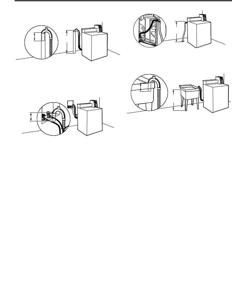
DRAIN SYSTEM
Drain system can be installed using a floor drain, wall standpipe, floor standpipe, or laundry tub. Select method you need.
Floor standpipe drain system
990 mm  (39")
(39") 
203 mm  (8")
(8") 
Minimum diameter for a standpipe drain: 51 mm (2"). Minimum carry-away capacity: 38 L (10 gal.) per minute. Top of standpipe must be at least 990 mm (39") high; install no higher than
2.44 m (96") from bottom of washer.
Wall standpipe drain system
203 mm (8")
See requirements for floor standpipe drain system.
Floor drain system
710 mm (28")
Floor drain system requires a Siphon Break Kit (Part Number 285320). Minimum siphon break: 710 mm (28") from bottom of washer. Additional hoses may be needed.
Laundry tub drain system
203 mm |
|
(8") |
990 mm |
|
(39") |
Minimum capacity: 76 L (20 gal.). The top of the laundry tub must be at least 990 mm (39") above floor.
12
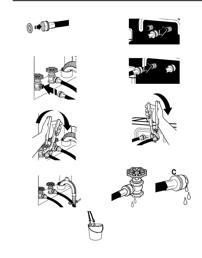
CONNECT INLET HOSES
Insert new hose washers (supplied) into each end of the inlet hoses. Firmly seat the washers in the couplings.
NOTE: Use new hoses supplied with the washer. Do not reuse old hoses.
Connect Inlet Hoses to Washer
1.Attach cold water hose to cold water inlet valve marked with a blue ring. Screw coupling by hand until it is snug.
Washer Coupling
Connect Inlet Hoses to Water Faucets
1.Attach hose to hot water faucet. Screw on coupling until it is seated on washer. Repeat process for cold water.
2.Use pliers to tighten the couplings an additional two-thirds turn.
IMPORTANT: Do not overtighten or use tape or sealants on valve when attaching to faucets or washer. Damage can result.
3. Secure drain hose to inlet hose with zip strap.
Clear Water Lines
ν Run water through both faucets and inlet hoses, into a laundry tub, drainpipe, or bucket to get rid of particles in the water lines that might clog the inlet valve screens.
νCheck the temperature of the water to make sure that the hot water hose is connected to the hot water faucet and that the cold water hose is connected to the cold water faucet.
2.Attach hot water hose to hot water inlet valve marked with a red ring. Screw coupling by hand until it is snug.
3. Use pliers to tighten couplings an additional two-thirds turn.
NOTE: Do not overtighten. Damage to the valve can result.
4.Turn on water faucets to check for leaks. A small amount of water may enter washer. It will drain later.
NOTE: Replace inlet hoses after 5 years of use to reduce the risk of hose failure. Record hose installation or replacement dates on the hoses for future reference.
Periodically inspect and replace hoses if bulges, kinks, cuts, wear, or leaks are found.
13
ELECTRICAL REQUIREMENTS
νA 220–240 volt, 50 Hz., AC-only, 10-amp, fused electric supply is required. A time-delay fuse or circuit breaker is recommended. It is recommended that a separate circuit serving only this appliance be provided.
νAfter installation, access to mains plug or disconnection from mains supply via a double-pole switch must be ensured at all times in order to ensure immediate deactivation of the washer in case of emergency.
νThis washer is equipped with a power supply cord having an earthing plug. The plug should be accessible for disconnection from the supply.
νIf the supply cord is damaged, it must be replaced by the manufacturer, its service agent, or similarly qualified persons in order to avoid a hazard.
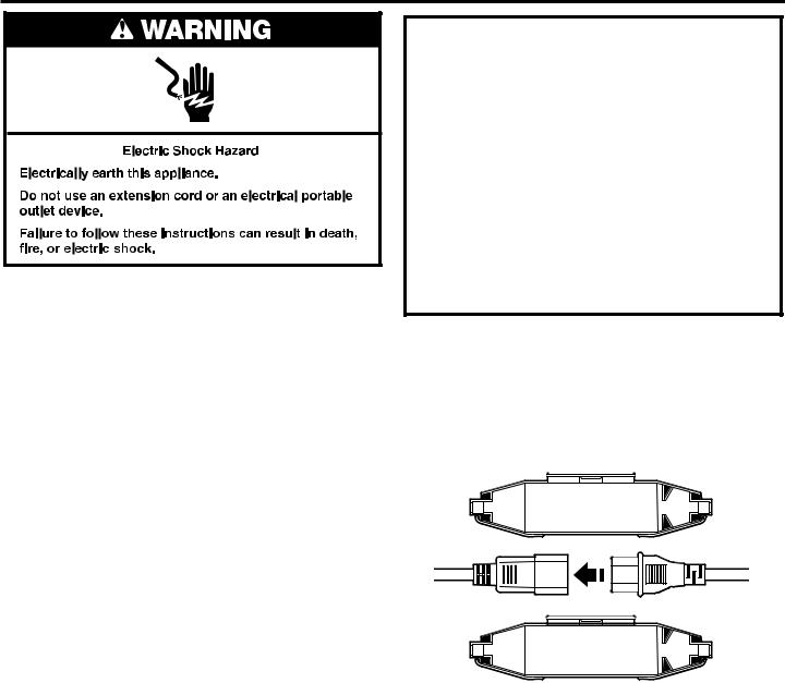
EARTHING INSTRUCTIONS
This washer must be earthed. In the event of a malfunction or breakdown, earthing will reduce the risk of electric shock by providing a path of least resistance for electric current. This washer is equipped with a cord having an equipment-earthing conductor and an earthing plug. The plug must be plugged into an appropriate outlet that is properly installed and earthed in accordance with all local codes and ordinances.
WARNING: Improper connection of the equipmentearthing conductor can result in a risk of electric shock. Check with a qualified electrician or serviceman if you are in doubt as to whether the appliance is properly earthed.
Do not modify the plug provided with the appliance – if it will not fit the outlet, have a proper outlet installed by a qualified electrician.
Using the universal cord included with this washer:
This washer is equipped with a universal cord with interchangeable plugs.
1.To use the universal cord, select the plug end that fits your electrical outlet, and plug it into the adapter on the supply cord.
2.Secure the plug end in place on the cord by aligning the 2 cover halves over the cord adapter and clipping them together.
14
COMPLETE INSTALLATION
θCheck electrical requirements. Be sure that you have the correct electrical supply and the recommended earthing method.
θCheck that all parts are now installed. If there is an extra part, go back through steps to see what was skipped.
θCheck that you have all of your tools.
θCheck that shipping materials were completely removed from washer.
θDispose of/recycle all packaging materials.
θCheck that the water faucets are on.
θCheck for leaks around faucets and inlet hoses.
θRemovewasher. film from console and any tape remaining on
θPlug into an earthed outlet or connect power.
θCheck that circuit breaker is not tripped or fuse is not blown.
θStart washer using the payment system (if available) to check that the wash cycle completes without an error code or water leak.
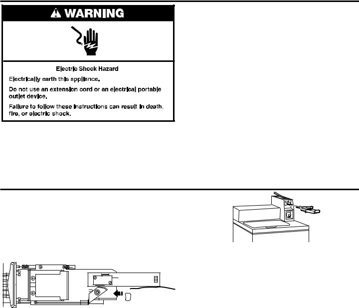
INSTALLING COIN SLIDE AND COIN BOX
The coin slide mechanism, service door lock and key, and coin box lock and key are not included with some models but can be obtained from the usual industry sources.
Remove the service door of the meter case by lifting it up at the back. Install the money-accepting device. (Refer to manufacturer’s instructions for proper installation.)
An earthing connection is needed for the coin slide, which
can be made by connecting the available harness (W10846503) to the coin slide.
 Earthing
connection
Install a lock and cam on the meter case service door. Install the coin vault with lock and key in the meter case opening.
For Free Vend, an OPL kit can be purchased from Whirlpool. Whirlpool part number W10222023.
15
ELECTRONIC CONTROLS SET-UP INSTRUCTIONS (PD & PN MODELS)
Basic Operation of Commercial Washer
■■ For additional information, see www.MaytagCommercialLaundry.com.
IMPORTANT
Electrostatic Discharge (ESD)
Sensitive Electronics
ESD problems are present everywhere. ESD may damage or weaken the electronic control assembly. The new control
assembly may appear to work well after repair is finished, but failure may occur at a later date due to ESD stress.
■■ Use an anti-static wrist strap. Connect wrist strap to green ground connection point or unpainted metal in the washer.
-OR-
Touch your finger repeatedly to a green earth connection point or unpainted metal in the washer.
■■ Before removing the part from its package, touch the anti-static bag to a green earth connection point or unpainted metal in the washer.
■■ Avoid touching electronic parts or terminal contacts; handle electronic control assembly by edges only.
■■ When repackaging failed electronic control assembly in anti-static bag, observe above instructions.
GENERAL INFORMATION
Blank Display
This condition indicates the washer is inoperative.
‘0 Minutes’ showing in display
This condition indicates the washer cannot be operated. Coins dropped or debit inputs during this condition will be stored in escrow but cannot be used until normal operation is restored by opening and closing the door. If a door switch fails, it must be replaced before normal operation can be restored.
Cold Start (initial use)
Washer is programmed at the factory as follows:
■■ POWERWASH = 12 min agitation NORMAL = 9 min agitation DELICATES = 6 min agitation NORMAL ECO = 8 min agitation
■■ NORMAL = 1 rinse and 2 minutes of rinse agitation POWERWASH = 1 deep rinse with spin-out DELICATES = 1 deep rinse with spin-out NORMAL ECO = 1 spray rinse
■■ NORMAL = $2.00 DELICATES = $1.75 POWERWASH = $2.50 NORMAL ECO = $1.75
Warm Start (after power failure)
After a delay of up to 8 seconds, the washer is restored to
the portion of the cycle that existed at time of the power failure. To continue the cycle, press START/PAUSE.
Free Cycles
This is established by setting the cycle price to zero. When this happens, ‘SELECT CYCLE’ will appear and cycle price will show 0.00.
Display
After the washer has been installed and plugged in, the display will show ‘SYnC’ for a few seconds, then ‘0 MINUTES’. Once the washer has been plugged in and the washer lid opened and closed, the display will show the price. In washers set for free cycles, the display will flash ‘SELECT CYCLE’, and will display ‘PRICE 0.00’.
|
CYCLES |
OPTIONS |
| <![if ! IE]> <![endif]>WATER |
POWERWASH |
TEMPERATURE |
NORMAL |
SOIL LEVEL |
|
| <![if ! IE]> <![endif]>DEEP |
|
|
|
DELICATES |
EXTRA RINSE |
|
NORMAL |
|
|
ECO |
|
16
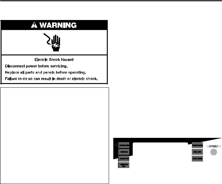
ELECTRONIC CONTROLS SET-UP INSTRUCTIONS
Control Set-Up Procedures
IMPORTANT: Read all instructions before operating.
The top three key pads on the left side, the top key pad on the right side, and the digital display are used to set up the controls. The display can contain 4 numbers and/or letters and a decimal point. These are used to indicate the set-up codes and related code values available for use in programming the washer.
How to use the key pads to program the controls
1.The POWERWASH key pad is used to adjust the values associated with set-up codes. Pressing the key pad will increment the value.
Rapid adjustment is possible by holding the key pad down.
2.The NORMAL key pad will advance you through the set-up codes. Pressing the key pad will advance you to the next available set-up code. Holding the key pad down
will automatically advance through the set-up codes at a rate of one (1) per second.
3.The DELICATES key pad is used to select or deselect options.
4.The TEMPERATURE key pad is used to decrease set-up code value.
Start Operating Setup
■■ PD Models: Insert access door key, turn, and lift to remove access door.
■■ PR models set for free vend: Refer to bottom of page 17 for entering operating setup.
IMPORTANT: The console must not be opened unless power is first removed from the washer. To access connector AA1:
gUnplug washer or disconnect power.
gOpen console, disconnect plug on AA1, close console.
gPlug in washer or reconnect power.
The washer is now in the set-up mode.
Before proceeding, it is worth noting that, despite all of the options available, an owner can simply choose to uncrate a new commercial washer, hook it up, plug it in, and have a unit that operates.
Set-Up Codes
■■ The NORMAL key pad will advance from code to code. ■■ The POWERWASH key pad will increase the code value. ■■ The DELICATES key pad will select or deselect options.
■■ The TEMPERATURE key pad will decrease the code value.
The set-up code is indicated by the one or two left-hand characters. The set-up code value is indicated by the two or three right-hand characters.
CODE |
EXPLANATION |
6.07DELICATES Regular Cycle Vend Price - Increase or decrease
DELICATES between 0 and 200 by pressing the POWERWASH or TEMPERATURE key pad. Factory preset for 7 coins = $1.75.
6.07NORMAL ECO Regular Cycle Vend Price - Increase or
NORMAL |
decrease between 0 and 200 by pressing the POWERWASH |
ECO |
or TEMPERATURE key pad. Factory preset for 7 coins = $1.75. |
6.07POWERWASH Regular Cycle Vend Price - Increase or
POWERWASH decrease between 0 and 200 by pressing the POWERWASH or TEMPERATURE key pad. Factory preset for 7 coins = $1.75.
6.08NORMAL Regular Cycle Vend Price - Increase or decrease
NORMAL between 0 and 200 by pressing the POWERWASH or TEMPERATURE key pad. Factory preset for 8 coins = $2.00.
gPress the NORMAL key pad once to advance to next code.
7.00ADDITIONAL WASH TIME
7.00This is the number of minutes that can be added to a Wash Cycle.
Choose from 00-05 minutes by pressing the POWERWASH key pad.
gPress the NORMAL key pad once to advance to next code.
8.00ADDITIONAL RINSE TIME
8.00This is the number of minutes that can be added to a RINSE Cycle. Choose from 00-05 minutes by pressing the POWERWASH key pad.
gPress the NORMAL key pad once to advance to next code.
9.00CYCLE COUNTER OPTION
This option is either SELECTED ‘ON’ or NOT SELECTED ‘OFF’.
9.00Not Selected ‘OFF’.
9.0C |
Selected ‘ON’ and not able to be deselected. |
|
Press the DELICATES key pad 3 consecutive times to select ‘ON’. |
|
Once selected ‘ON’ it cannot be deselected. |
gPress the NORMAL key pad once to advance to next code.
1.00MONEY COUNTER OPTION
This option is either SELECTED ‘ON’ or NOT SELECTED ‘OFF’.
1.00Not Selected ‘OFF’.
1.0C |
Selected ‘ON’. |
|
Press the DELICATES key pad 3 consecutive times to select ‘ON’ |
|
and 3 consecutive times to remove (Not Selected ‘OFF’.) Counter |
|
resets by going from ‘OFF’ to ‘ON’. |
|
|
1.C0 |
Selected ‘ON’ and not able to be deselected. |
|
To select ‘ON’ and not able to be deselected, first select ‘ON’, |
|
then within 2 seconds press the DELICATES key pad twice, |
|
the POWERWASH key pad once, and exit the set-up mode. |
gPress the NORMAL key pad once to advance to next code.
2.00SPECIAL PRICING OPTION
This option is either SELECTED ‘ON’ or NOT SELECTED ‘OFF’.
2.00Not Selected ‘OFF’.
2.SP |
Selected ‘ON’. Press the DELICATES key pad once for this |
|
selection. |
If SPECIAL PRICING OPTION is selected, there is access to codes ‘3.’ through ‘9.’.
NOTE: An external battery needs to be added to keep the clock running during periods of power outages.
gPress the NORMAL key pad once to advance to next code.
17
ELECTRONIC CONTROLS SET-UP INSTRUCTIONS
CODE |
EXPLANATION |
|
|
OPTIONS TO USE IF SPECIAL PRICING IS SELECTED:
3.07DELICATES Special Cycle Vend Price - Increase or decrease
DELICATES between 0 and 200 by pressing the POWERWASH or TEMPERATURE key pad. Factory preset for 7 coins = $1.75.
3.07NORMAL ECO Special Cycle Vend Price - Increase between 0
NORMAL ECO and 200 by pressing the POWERWASH or decrease by pressing the TEMPERATURE key pad. Factory preset for 7 coins = $1.75.
3.07POWERWASH Special Cycle Vend Price - Increase or
POWERWASH decrease between 0 and 200 by pressing the POWERWASH or TEMPERATURE key pad. Factory preset for 7 coins = $1.75.
3.08NORMAL Special Cycle Vend Price - Increase or decrease
NORMAL between 0 and 200 by pressing the POWERWASH or TEMPERATURE key pad. Factory preset for 8 coins = $2.00.
gPress the NORMAL key pad once to advance to next code.
5.00TIME-OF-DAY CLOCK, MINUTES
5.00This is the TIME-OF-DAY CLOCK, minute setting; select between 0 and 59 minutes by pressing the POWERWASH or TEMPERATURE key pad.
gPress the NORMAL key pad once to advance to next code.
6.00TIME-OF-DAY CLOCK, HOURS NOTE: Uses military time or 24 hr. clock.
6.00This is the TIME-OF-DAY CLOCK, hour setting; select between 0 and 23 hours by pressing the POWERWASH or TEMPERATURE key pad.
gPress the NORMAL key pad once to advance to next code.
7.00SPECIAL PRICE START HOUR
NOTE: Uses military time or 24 hr. clock.
7.00This is the start hour; select between 0 and 23 hours by pressing the POWERWASH or TEMPERATURE key pad.
gPress the NORMAL key pad once to advance to next code.
8.00SPECIAL PRICE STOP HOUR
NOTE: Uses military time or 24 hr. clock.
8.00This is the stop hour; select between 0 and 23 hours by pressing the POWERWASH or TEMPERATURE key pad.
gPress the NORMAL key pad once to advance to next code.
9.00SPECIAL PRICE DAY
9.10This represents the day of the week and whether special pricing is selected for that day. A number followed by ‘0’ indicates no selection that particular day (9.10). A number followed by an ‘S’ indicates selected for that day (9.1S).
Days of the week (1-7) can be chosen by pressing the POWERWASH key pad. Press the POWERWASH key pad once to select special pricing for each day chosen.
When exiting set-up code ‘9’, the display must show current day of week:
DISPLAY |
DAY OF WEEK |
CODE (selected) |
|
10 |
Day 1 = Sunday |
1S |
|
20 |
Day 2 = Monday |
2S |
|
30 |
Day 3 = Tuesday |
3S |
|
40 |
Day 4 |
= Wednesday |
4S |
50 |
Day 5 |
= Thursday |
5S |
60 |
Day 6 |
= Friday |
6S |
70 |
Day 7 |
= Saturday |
7S |
gPress the NORMAL key pad once to advance to next code.
18
CODE |
EXPLANATION |
|
|
A.00 |
VAULT VIEWING OPTION |
|
This option is either SELECTED ‘ON’ or NOT SELECTED ‘OFF’. |
|
|
A.00 |
Not Selected ‘OFF’. |
|
|
A.SC |
Selected ‘ON’. Press the DELICATES key pad once for this |
|
selection. When selected, the money and/or cycle counts will be |
|
viewable (depending on what is selected) when the coin box is |
|
removed. |
|
|
gPress the NORMAL key pad once to advance to next code.
b.05 |
VALUE OF COIN 1 |
|
|
b.05 |
This represents the value of coin 1 in number of 5% increments |
|
of the larger coin value. 5 x 5% = 25%. |
|
By pressing the POWERWASH or TEMPERATURE key pad, |
|
there is the option of between 1 and 199 for the quantity of 5% |
|
increments. |
|
|
gPress the NORMAL key pad once to advance to next code.
C.20 |
VALUE OF COIN 2 |
|
|
C.20 |
This represents the value of coin 2 in number of 5% increments |
|
of the larger coin value. 2 x 5% = 100%. |
|
By pressing the POWERWASH or TEMPERATURE key pad, |
|
there is the option of between 1 and 199 for the quantity of 5% |
|
increments. |
|
|
gPress the NORMAL key pad once to advance to next code.
d.00 |
COIN SLIDE OPTION |
|
This option is either SELECTED ‘ON’ or NOT SELECTED ‘OFF’. |
|
|
d.00 |
Not Selected ‘OFF’. |
|
|
d.CS |
Selected ‘ON’. Press the DELICATES key pad 3 consecutive times |
|
for this selection. |
|
When coin slide mode is selected, set ‘b.’ equal to value of slide |
|
in 5% increments. Set Step 6 (regular cycle price) and Step 3 |
|
(special cycle price) to number of slide operations. If the installer |
|
sets up ‘CS’ on a coin drop model, it will not register coins. |
|
|
gPress the NORMAL key pad once to advance to next code.
E.00 |
ADD COINS OPTION |
|
This option is either SELECTED ‘ON’ or NOT SELECTED ‘OFF’. |
|
This option causes the customer display to show the number |
|
of coins (coin 1) to enter, rather than the monetary amount. |
|
|
E.00 |
Not Selected ‘OFF’. |
|
|
E.AC |
Selected ‘ON’. Press the DELICATES key pad 3 consecutive times |
|
for this selection. |
|
|
gPress the NORMAL key pad once to advance to next code.
H.00 |
COLD Temperature Upgrade Price - Increase or decrease |
COLD |
between 0 and 200 by pressing the POWERWASH or |
|
TEMPERATURE key pad. Factory preset for 0 coins = $0.00. |
H.00 |
COOL Temperature Upgrade Price - Increase or decrease |
COOL |
between 0 and 200 by pressing the POWERWASH or |
|
TEMPERATURE key pad. Factory preset for 1 coins = $0.25. |
|
|
H.00 |
WARM Temperature Upgrade Price - Increase or decrease |
WARM |
between 0 and 200 by pressing the POWERWASH or |
|
TEMPERATURE key pad. Factory preset for 2 coins = $0.50. |
|
|
H.00 |
HOT Temperature Upgrade Price - Increase or decrease between |
HOT |
0 and 200 by pressing the POWERWASH or TEMPERATURE key |
|
pad. Factory preset for 3 coins = $0.75. |
|
|
H.00 |
HEAVY SOIL LEVEL Upgrade Price - Increase or decrease |
HEAVY |
between 0 and 200 by pressing the POWERWASH or |
|
TEMPERATURE key pad. Factory preset for 1 coins = $0.25. |
|
|
ELECTRONIC CONTROLS SET-UP INSTRUCTIONS
CODE |
EXPLANATION |
|
|
H.00 |
EXTRA RINSE Upgrade Price - Increase or decrease between 0 |
EXTRA |
and 200 by pressing the POWERWASH or TEMPERATURE key |
RINSE |
pad. Factory preset for 1 coins = $0.25. |
|
|
|
|
gPress the NORMAL key pad once to advance to next code.
J.Cd |
COIN/DEBIT OPTION |
|
|
J.Cd |
Both coin & debit selected. |
|
|
J.C_ |
Coins selected, debit disabled. Press the DELICATES key pad |
|
3 times for this selection. |
|
|
J._d |
Debit Card selected, coins disabled. Press the DELICATES key |
|
pad 3 times for this selection. |
|
|
J.Ed |
Enhanced Debit is self-selected when a Generation 2 card reader |
|
is installed in the washer. The Ed option cannot be manually |
|
selected or deselected. |
|
|
gPress the NORMAL key pad once to advance to next code.
L.00 |
PRICE SUPPRESSION OPTION |
|
This option causes the customer display to show ‘ADD’ or |
|
‘AVAILABLE’ rather than the amount of money to add. (Used |
|
mainly in debit installations.) |
|
|
L.00 |
Not Selected ‘OFF’. |
|
|
L.PS |
Selected ‘ON’. Press the DELICATES key pad once for this |
|
selection. |
gPress the NORMAL key pad once to advance to next code.
n. CE |
CLEAR ESCROW OPTION |
|
When selected, money held in escrow for 30 minutes without |
|
further escrow or cycle activity will be cleared. |
|
|
n. CE |
Selected ‘ON’. |
|
|
n. 00 |
Not selected ‘OFF’. Press the DELICATES key pad once to |
|
deselect this selection. |
|
|
gPress the NORMAL key pad once to advance to next code.
U.00 |
COIN (HUNDREDTH) INCREMENT OFFSET |
|
|
U.00 |
For use with card reader applications only. |
|
|
gPress the NORMAL key pad once to advance to next code.
A3.03 NORMAL Cycle Settings. Allows the owner to select the cycle default options of Water Temperature, Soil Level, and Extra Rinse.
See Table 1 for specific settings. Normal is set to 03 from the factory.
A4.01 DELICATES Cycle Settings. Allows the owner to select the cycle default options of Water Temperature, Soil Level, and Extra Rinse.
See Table 1 for specific settings. Delicates is set to 01 from the factory.
A5.1C POWERWASH Cycle Settings. Allows the owner to select the cycle default options of Water Temperature, Soil Level, and Extra Rinse.
See Table 1 for specific settings. Powerwash is set to 1C from the factory.
A6.03 NORMAL ECO Cycle Settings. Allows the owner to select the cycle default options of Water Temperature, Soil Level, and Extra Rinse.
See Table 1 for specific settings. Normal Eco is set to 03 from the factory.
If cycle counter (9.0C) is selected, the following is true:
1 xx Number of cycles in THOUSANDS. |
1 02 |
= 2,000 |
|
2xxx Number of cycles in ONES. |
2225 |
= 225 |
|
|
|
|
|
|
TOTAL CYCLES |
= 2,225 |
|
This is “VIEW ONLY” and cannot be cleared.
Press the NORMAL key pad once to advance to next code.
If money counter (1.0C or 1.C0) is selected, the following is true:
3 xx Number in THOUSANDS. 4xxx Number in ONES.
5 xx Number of HUNDRETHS.
END OF SET-UP PROCEDURES
EXIT FROM SET-UP MODE
■■ PD Models: Reinstall access door.
If preferred, just wait through 2 minutes of inactivity. All settings will be saved and the display will revert to Select Cycle screen.
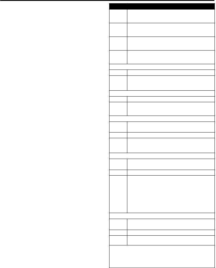
Table 1
A3, A4, |
Extra |
Soil Level |
Water |
A3, A4, |
Extra |
Soil Level |
Water |
A5, A6 |
Rinse |
(Heavy-On, |
Temp |
A5, A6 |
Rinse |
(Heavy-On, |
Temp |
|
|
Normal-Off) |
|
|
|
Normal-Off) |
|
|
|
|
|
|
|
|
|
00 |
Off |
Off |
Tap |
10 |
On |
Off |
Tap |
|
|
|
Cold |
|
|
|
Cold |
|
|
|
|
|
|
|
|
01 |
Off |
Off |
Cold |
11 |
On |
Off |
Cold |
|
|
|
|
|
|
|
|
02 |
Off |
Off |
Cool |
12 |
On |
Off |
Cool |
|
|
|
|
|
|
|
|
03 |
Off |
Off |
Warm |
13 |
On |
Off |
Warm |
|
|
|
|
|
|
|
|
04 |
Off |
Off |
Hot |
14 |
On |
Off |
Hot |
|
|
|
|
|
|
|
|
08 |
Off |
On |
Tap |
18 |
On |
On |
Tap |
|
|
|
Cold |
|
|
|
Cold |
|
|
|
|
|
|
|
|
09 |
Off |
On |
Cold |
19 |
On |
On |
Cold |
|
|
|
|
|
|
|
|
A |
Off |
On |
Cool |
1A |
On |
On |
Cool |
|
|
|
|
|
|
|
|
B |
Off |
On |
Warm |
1B |
On |
On |
Warm |
|
|
|
|
|
|
|
|
C |
Off |
On |
Hot |
1C |
On |
On |
Hot |
|
|
|
|
|
|
|
|
Technician Service Access Code
This method is only available on PR washers set to free vend (6 00).
To enter service mode:
Press the POWERWASH, EXTRA RINSE, TEMPERATURE, and DELICATES key pads within 10 seconds.
To exit service mode:
Wait 2 minutes without touching any key pads (without diagnostic modes running)
or
Power down the washer, then reapply power.
NOTE: If a service cycle is in progress upon exiting service mode, the cycle will complete normally with cycle status information displayed. The display will resume normal customer operation mode when the cycle ends.
19

WASHER DISPOSAL
This appliance is marked according to the European directive 2012/19/EU on Waste Electrical and Electronic Equipment (WEEE).
By ensuring this product is disposed of correctly, you will help avoid potential negative consequences for the environment and human health, which could otherwise be caused by inappropriate waste handling of this product.
The symbol on the product, or on the documents accompanying the product, indicates that this appliance may not be treated as household waste. Instead it shall be handed over to the applicable collection point for the recycling of electrical and electronic equipment.
Disposal must be carried out in accordance with local environmental regulations for waste disposal.
For more detailed information about treatment, recovery and recycling of this product, please contact your local city ofƒce, your household waste disposal service or the shop where you purchased the product.
20
MAYTAG® COMMERCIAL LAUNDRY
LIMITED WARRANTY
IF YOU NEED SERVICE:
Contact your authorized Maytag® Commercial Laundry distributor. To locate your authorized Maytag® Commercial Laundry distributor, visit www.MaytagCommercialLaundry.com.
For written correspondence:
Maytag® Commercial Laundry Service Department
2000 N M 63
Benton Harbor, Michigan 49022-2632 USA
|
FIVE YEAR LIMITED WARRANTY |
WHAT IS COVERED |
WHAT IS NOT COVERED |
FIVE YEAR LIMITED WARRANTY |
1. All other costs including labor, transportation, shipping, or custom duties for |
(PARTS ONLY — LABOR NOT INCLUDED) |
covered parts. |
For the first five years from the original date of purchase, when this commercial appliance is installed, maintained, and operated according to the instructions attached to or furnished with the product, Maytag brand of Whirlpool Corporation (hereafter “Maytag”) will pay for factory specified replacement parts to correct defects in materials or workmanship that existed when this commercial appliance was purchased. This limited warranty does not include labor.
YOUR SOLE AND EXCLUSIVE REMEDY UNDER THIS LIMITED WARRANTY SHALL BE PRODUCT REPAIR AS PROVIDED HEREIN. Maytag recommends that you use an “authorized” service provider to diagnose and repair your Commercial Laundry product.
Maytag will not be responsible under this warranty to provide additional replacement parts as a result of incorrect diagnosis or repair by an “unauthorized” service company. Except in the European Union, this limited warranty is valid only when the commercial appliance is used in the country in which it was purchased. This limited warranty is effective from the date of the original consumer purchase. Proof
of original purchase date is required to obtain service under this limited warranty.
2.Factory specified replacement parts if this commercial appliance is used for other than normal, commercial use or when it is used in a manner that is inconsistent to published user or operator instructions and/or installation instructions.
3.Service calls to correct the installation of your commercial appliance, to instruct you on how to use your commercial appliance, to replace or repair house fuses, or to correct external wiring or plumbing.
4.Service calls to repair or replace appliance light bulbs, air filters, or water filters. Consumable parts are excluded from warranty coverage.
5.Damage resulting from improper handling of product during delivery, theft, accident, alteration, misuse, abuse, fire, flood, acts of God, improper installation, installation not in accordance with local electrical or plumbing codes, or use of products not approved by Maytag.
6.Pick up and delivery. This commercial appliance is designed to be repaired on location.
7.Repairs to parts or systems resulting from unauthorized modifications made to the commercial appliance.
8.The removal and reinstallation of your commercial appliance if it is installed in an inaccessible location or is not installed in accordance with published installation instructions.
9.Damage resulting from exposure to chemicals.
10.Changes to the building, room, or location needed in order to make the commercial appliance operate correctly.
11.Factory specified replacement parts on commercial appliances with original model/serial numbers that have been removed, altered, or cannot be easily determined.
12.Discoloration, rust, or oxidation of stainless steel surfaces.
13.Factory specified replacement parts as a result of incorrect diagnosis or repair by an “unauthorized” service company.
The cost of repair or replacement under these excluded circumstances shall be borne by the customer.
DISCLAIMER OF IMPLIED WARRANTIES
IMPLIED WARRANTIES, INCLUDING ANY IMPLIED WARRANTY OF MERCHANTABILITY OR IMPLIED WARRANTY OF FITNESS FOR A PARTICULAR PURPOSE, ARE LIMITED TO FIVE YEARS OR THE SHORTEST PERIOD ALLOWED BY LAW. Some locations may not allow limitations on the duration of implied warranties of merchantability or fitness, so this limitation may not apply to you. This warranty gives you specific legal rights, and you also may have other rights that vary.
DISCLAIMER OF REPRESENTATIONS OUTSIDE OF WARRANTY
Maytag makes no representations about the quality, durability, or need for service or repair of this major appliance other than the representations contained in this Warranty. If you want a longer or more comprehensive warranty than the limited warranty that comes with this major appliance, you should ask your retailer about buying an extended warranty. The benefits to you given by this warranty are in addition to other rights and remedies available to you under a law in relation to the goods or service to which this warranty relates. Please contact Maytag for further information on warranty terms.
LIMITATION OF REMEDIES; EXCLUSION OF INCIDENTAL AND CONSEQUENTIAL DAMAGES
YOUR SOLE AND EXCLUSIVE REMEDY UNDER THIS LIMITED WARRANTY SHALL BE PRODUCT REPAIR AS PROVIDED HEREIN. MAYTAG SHALL NOT BE LIABLE FOR INCIDENTAL OR CONSEQUENTIAL DAMAGES. Some locations do not allow the
exclusion or limitation of incidental or consequential damages, so these limitations and exclusions may not apply to you. This warranty gives you specific legal rights, and you also may have other rights that vary by location.
01/17
21

SÉCURITÉ DU LAVE-LINGE
REMARQUE : L'installation et la maintenance doivent être réalisées par un technicien agréé par Whirlpool.
IMPORTANTES INSTRUCTIONS DE SECURITE
AVERTISSEMENT : Afin de réduire le risque d’incendie, de choc électeiue ou de blessures corporellles lors de l’utilisation du lave-linge, il convient d’observer certaines précautions fondamentales, notamment :
νLire toutes les instructions avant d’utiliser . le lave-linge.
νNe pas laver des articles qui ont été précédemment nettoyés, lavés, trempés ou tachés avec de l’essence, un solvant pour nettoyage à sec ou d’autres substances inflammables ou explosives; ces substances dégagent des vapeurs qui pourraient s’enflammer ou provoquer une explosion.
νNe pas ajouter d’essence, de solvant pour nettoyage à sec ou d’autre substance inflammable ou explosive à l’eau de lavage; ces substances dégagent des vapeurs qui pourraient s’enflammer ou provoquer une explosion.
νDans certains conditions, un circuit d’eau chaude qui n’a pas été utilisé depuis 2 semaines ou plus peut contenir de l’hydrogène. L’HYDROGENE EST UN GAZ EXPLOSIF.
Si le circuit d’eau chaude est resté inutilisé pendant une telle période, ouvrir tous les robinets d’eau chaude et laisser l’eau s’écouler pendant plusieurs minutes avant d’utiliser
le lave-linge. Ceci permettra l’évacuation de toute accumulation d’hydrogène. Le gaz est inflammable : ne pas fumer ou utiliser une flamme nue durant cette période.
νL’appareil doit être débranché de sa source de courant électrique durant les interventions de service et le remplacement des pièces. Après son débranchement, la fiche du cordon d’alimentation doit rester bien visible pendant toute la durée de l’intervention afin de s’assurer que l’appareil n’est pas sous tension.
νCet appareil ne convient pas à une utilisation par des enfants ou par des personnes à capacités physiques, sensorielles ou mentales réduites, ou dépourvues d’expérience et de connaissances, à moins qu’elles ne soient placées sous supervision ou qu’elles aient reçu des instructions concernant l’utilisation sécuritaire de l’appareil par une personne responsable de leur sécurité. De telles personnes doivent aussi comprendre les risques possibles qu’implique l’utilisation.
νCet appareil peut être utilisé par des enfants
àpartir de 8 ans et des personnes dont les capacités physiques, sensorielles ou mentales sont réduites ou des personnes manquant d’expérience et de connaissances, mais uniquement si ces enfants et personnes sont placés sous la surveillance d’une personne responsable ou ont reçu des instructions sur l’utilisation en toute sécurité de l’appareil.
νLes enfants de moins de 3 ans doivent être tenus
àdistance de l’appareil ou être surveillés en permanence.
CONSERVER CES INSTRUCTIONS
22

νCet appareil est conçu pour un usage domestique et des utilisations similaires telles que les suivantes : espace cuisine du personnel dans les magasins, bureaux et autres environnements de travail ; fermes ; par les clients dans les hôtels, les motels et
les autres environnements de type résidentiel ; dans les environnements de type chambres d’hôtes, zones communes dans les immeubles d’appartements ou dans des laveries.
νAucun lave-linge ne peut complètement enlever l’huile. Ne pas faire sécher des articles qui ont été salis par tout genre d’huile (y compris les huiles de cuisson). Le nonrespect de ces instructions peut causer
un décès, une explosion ou un incendie.
νIl est recommandé de ne pas laver d’articles en fibre de verre dans un lave-linge payante. Si on lave ces articles dans le lave-linge, faire fonctionner un programme complet pour rincer les éventuels résidus restés dans le lave-linge.
νLes enfants qui effectuent le nettoyage et l’entretien doivent être supervisés.
νNe pas laisser des enfants jouer sur,
à l’intérieur de ou avec le lave-linge. Bien surveiller les enfants lorsque le lave-linge est utilisé à proximité d’enfants.
νAvant que le lave-linge ne soit mis hors service ou mis au rebut, enlever la porte ou le couvercle.
νNe pas mettre la main dans le lave-linge si le panier, la cuve ou l’agitateur sont en mouvement.
νNe pas installer au entreposer le lave-linge dans un endroit où il serait exposé aux intempéries.
νNe pas effectuer d’intervention non autorisée sur les commandes.
νAprès l’installation, l’accès à la prise secteur ou l’alimentation secteur via un interrupteur bipolaire doit être maintenu à tout moment pour assurer une désactivation immédiate du lave-linge en cas d’urgence.
νNe pas réparer ou au remplacer un composant quelconque du lave-linge, ni entreprendre une opération de service, si ce n’est spécifiquement recommandé dans ce manuel. Il est alors essential que la personne concernée comprenne ces instructions et soit compétente pour les exécuter.
νPour les instructions de liaison à la terre, voir “Spécifications électriques”.
CONSERVER CES INSTRUCTIONS
INSTRUCTIONS DE L’UTILISATION GÉNÉRAL
νLa pression de l’eau doit être de 138 à 690 kPa (20 à 100 lb/po2) pour le fonctionnement du lave-linge.
νUtiliser les tuyaux fournis avec le nouvel appareil ; ne pas réutiliser celui de l’appareil précédent.
νSi le cordon d’alimentation est endommagé, il doit être remplacé par le fabricant, son technicien d’entretien ou des personnes présentant une qualification similaire pour éviter tout risque.
TAILLE TYPIQUE DES CHARGES COMPLÈTES
Type de charge |
Suggestion de chargement |
Type de charge |
Suggestion de chargement |
|
|
|
|
Charge mixte |
3 draps (lit à 2 places) |
Vêtements de travail très sales |
3 pantalons |
|
4 taies d’oreiller |
|
3 chemises |
|
6 shorts |
|
1 combinaison |
|
8 T-shirts |
|
4 jeans |
|
2 chemises |
|
1 salopette |
|
2 chemisiers |
|
|
|
8 mouchoirs |
|
|
Pressage permanent |
2 draps (lit à 2 places) ou |
Tricots |
3 chemisiers |
|
1 drap (lit très grand) |
|
4 pantalons |
|
1 nappe |
|
6 chemises |
|
1 robe |
|
4 tricots |
|
1 chemisier |
|
4 robes |
|
2 pantalons |
|
|
|
3 chemises |
|
|
|
2 taies d’oreiller |
|
|
23

TRANSPORT DU LAVE-LINGE
νFermer les deux robinets d’eau. Débrancher et vidanger les tuyaux d’arrivée d’eau.
νDéconnecter le tuyau d’évacuation du système de vidange et vider l’eau qui reste dans un bac ou un seau. Déconnecter le tuyau d’évacuation de l’arrière du lave-linge.
νDébrancher le cordon d’alimentation.
νPlacer les tuyaux d’arrivée d’eau et le tuyau d’évacuation dans le panier du lave-linge.
νFaire passer le cordon d’alimentation par dessus le bord et le mettre dans le panier du lave-linge.
νReplacer le support d’emballage issu du matériel d’expédition d’origine à l’intérieur du lave-linge et réutiliser la base d’expédition pour soutenir le moteur et la cuve. Si vous n’avez plus l’emballage d’origine, placer des couvertures lourdes
ou des serviettes au-dessus du panier, entre le sommet du lave-linge et le pourtour de la cuve. Fermer le couvercle et placer du ruban adhésif sur le couvercle et jusqu’à la partie inférieure avant du lave-linge. Laisser le couvercle fermé par l’adhésif jusqu’à ce que le lave-linge soit installé à son nouvel emplacement.
SI VOUS AVEZ BESOIN D’ASSISTANCE OU SERVICE
Il se peut que l’installation nécessite des pièces supplémentaires. Contacter le revendeur autorisé d’appareils de buanderie à usage commercial où le lave-linge a été acheté ou un service d’entretien agréé.
Lors de votre appel, vous aurez besoin du numéro de modèle et de série du lave-linge. Ces deux numéros figurent sur la plaque signalétique située sur le lave-linge.
POUR CONTACTER LE SERVICE APRÈS-VENTE :
Adressez-vous à votre distributeur Maytag® Commercial Laundry agréé. Pour identifier le distributeur Maytag® Commercial Laundry agréé le plus proche, consultez le site Internet www.MaytagCommercialLaundry.com.
Pour écrire au service après-vente, utilisez cette adresse :
Maytag® Commercial Laundry Service Department
2000 N M 63
Benton Harbor, Michigan 49022-2632, États-Unis
24
 Loading...