


COMMERCIAL WASHER INSTALLATION INSTRUCTIONS
220–240-VOLT, 50-HZ MODELS
INSTRUCTIONS D’INSTALLATION
DU LAVE-LINGE COMMERCIAL
MODÈLES 220–240 V, 50 HZ
LAVADORA COMERCIAL INSTRUCCIONES DE INSTALACIÓN
MODELOS DE 220 Y 240 VOLTIOS, 50 HZ
LAVATRICE COMMERCIALE ISTRUZIONI D’INSTALLAZIONE
MODELLI A 220-240 V, 50 HZ
MAT14PD
W10045627A
www.maytagcommerciallaundry.com

Table of Contents
WASHER SAFETY...................................................................... |
3 |
INSTALLATION INSTRUCTIONS.............................................. |
6 |
WASHER DISPOSAL................................................................. |
3 |
Remove Shipping Strap....................................................... |
6 |
INSTALLATION REQUIREMENTS............................................ |
4 |
Connect the Hoses.............................................................. |
6 |
Tools and Parts.................................................................... |
4 |
Level the Washer................................................................. |
7 |
Location Requirements........................................................ |
4 |
Complete Installation ........................................................... |
8 |
Drain System....................................................................... |
5 |
Operating Tips ..................................................................... |
8 |
Electrical Requirements....................................................... |
5 |
ELECTRONIC CONTROLS SETUP............................................ |
9 |
|
|
WARRANTY.............................................................................. |
13 |
Table des matières
SECURITE DU LAVE-LINGE................................................... |
14 |
ÉLIMINATION DU LAVE-LINGE.............................................. |
14 |
EXIGENCES D’INSTALLATION............................................... |
15 |
Outillage et pièces............................................................. |
15 |
Exigences d’emplacement................................................ |
15 |
Système de vidange.......................................................... |
16 |
Spécifications électriques.................................................. |
16 |
INSTRUCTIONS D’INSTALLATION......................................... |
17 |
Enlever la sangle d’expédition........................................... |
17 |
Raccordement des tuyaux................................................. |
17 |
Réglage de l’aplomb du lave-linge.................................... |
18 |
Achever l’installation........................................................... |
19 |
Conseils d’utilisation .......................................................... |
19 |
PARAMÉTRAGE DES COMMANDES ÉLECTRONIQUES...... |
20 |
GARANTIE................................................................................. |
25 |
Índice
SEGURIDAD DE LA LAVADORA............................................. |
26 |
ELIMINACIÓN DE LA LAVADORA.......................................... |
26 |
REQUISITOS DE INSTALACIÓN............................................. |
27 |
Piezas y herramientas........................................................ |
27 |
Requisitos de ubicación.................................................... |
27 |
Sistema de desagüe.......................................................... |
28 |
Requisitos eléctricos.......................................................... |
28 |
INSTRUCCIONES DE INSTALACIÓN..................................... |
29 |
Cómo quitar la correa de embalaje................................... |
29 |
Conecte las mangueras..................................................... |
29 |
Nivelación de la lavadora................................................... |
30 |
Complete la instalación ..................................................... |
31 |
Consejos para el funcionamiento....................................... |
31 |
PROGRAMACIÓN DE LOS CONTROLES |
|
ELECTRÓNICOS....................................................................... |
32 |
GARANTIA................................................................................. |
37 |
Sommario
SICUREZZA DELLA LAVATRICE............................................ |
38 |
L’ELIMINAZIONE DELLA LAVATRICE.................................... |
38 |
REQUISITI D’INSTALLAZIONE............................................... |
39 |
Attrezzi e componenti........................................................ |
39 |
Requisiti di posizionamento............................................... |
39 |
Sistema di scarico............................................................. |
40 |
Requisiti elettrici................................................................ |
40 |
ISTRUZIONI D’INSTALLAZIONE............................................ |
41 |
Rimozione delle fascette d’imballaggio............................. |
41 |
Collegamento dei tubi........................................................ |
41 |
Livellamento della lavatrice................................................ |
42 |
Installazione completa ....................................................... |
43 |
Suggerimenti operativi ....................................................... |
43 |
CONFIGURAZIONE DEI CONTROLLI ELETTRONICI............ |
44 |
GARANZIA................................................................................ |
52 |
2

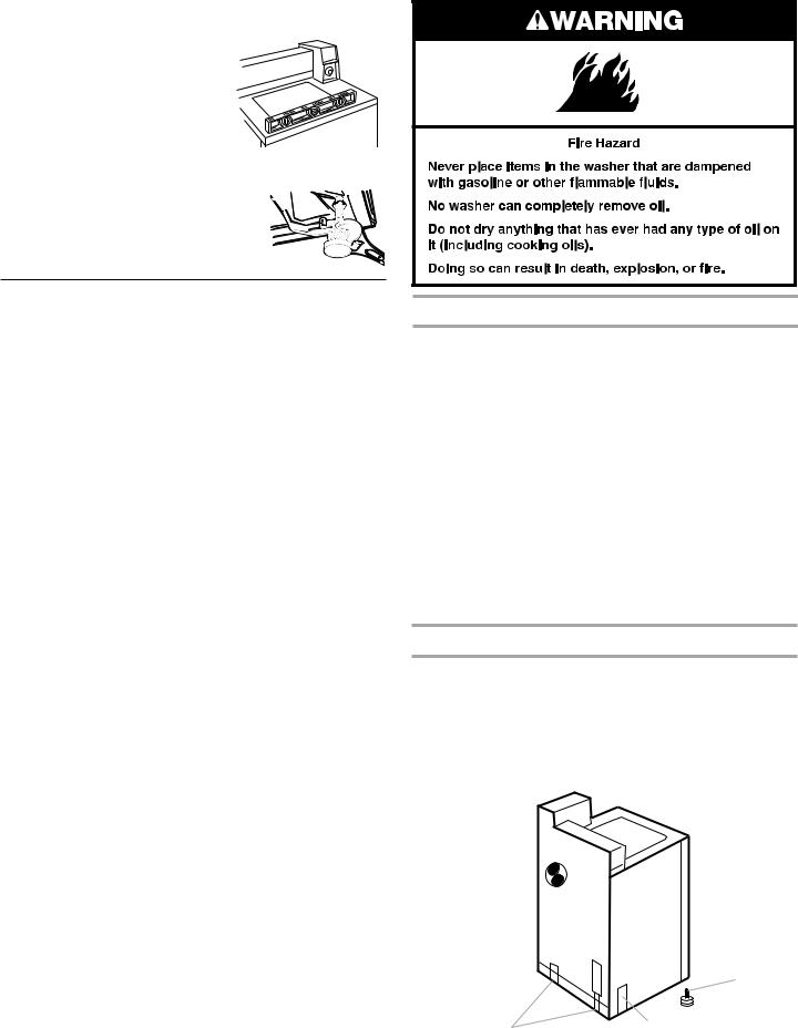
WASHER SAFETY
WASHER DISPOSAL
3

INSTALLATION REQUIREMENTS
Tools and Parts
Gather the required tools and parts before starting installation.
Tools needed
ν Level |
ν Flat-blade screwdriver |
ν Utility knife |
ν Pliers |
ν Scissors |
ν Bucket |
ν200 mm (8") or 250 mm (10") adjustable wrench
Parts supplied
Remove parts bag from washer. Check that all parts were included.
ν |
1 |
Hose clamp |
ν 2 Front-leveling legs |
|
ν |
2 |
Inlet hoses |
with nuts |
|
ν 1 Drain hose |
||||
ν |
4 |
Flat water hose washers |
||
|
|
ν Hose adapter |
||
|
|
|
||
|
|
|||
Technical |
Clothes |
|||
Specifications: |
Capacity: |
|||
|
|
|||
220 – 240 V, 50 Hz. AC |
MAT14PD: 5.9 Kg Max. |
|||
|
|
|||
650 Watts |
|
|||
|
|
|
|
|
|
|
|
|
|
Location Requirements
IMPORTANT: Do not install or store the washer where it will be exposed to the weather. Do not store or operate the washer in temperatures at or below 0°C (32°F). Some water can remain in the washer and can cause damage in low temperatures.
Proper installation is your responsibility.
You will need:
νA water heater set to deliver 60°C (140°F) water to the washer.
νAn earthed electrical outlet located within 1.2 m (4 ft) of where the power cord is attached to the back of the washer. See “Electrical Requirements.”
νHot and cold water taps located within 1.2 m (4 ft) of the back of the washer, and provide water pressure of 69–690 kPa (10–100 psi). A pressure reduction valve should be used in the supply line where inlet pressure entering the building exceeds 690 kPa (100 psi) to prevent damage to the washer mixing valve.
νA level floor with a maximum slope of 25 mm (1") under entire washer.
νA sturdy floor to support the washer weight (washer, water, and load) of 143 kgs (315 lbs).
νA 300 mm (12") minimum riser to provide an air cushion and prevent noise and damage to valves for a single washer installation.
νA floor drain should be provided under the bulkhead. Prefabricated bulkheads with electrical outlets, water supply lines, and drain facilities should be used only where local codes permit.
NOTE: Front access to the pump area is available by removing No. T20 TORX®† security screws and then removing the front panel.
®† Torx is a registered trademark of Saturn Fasteners, Inc.
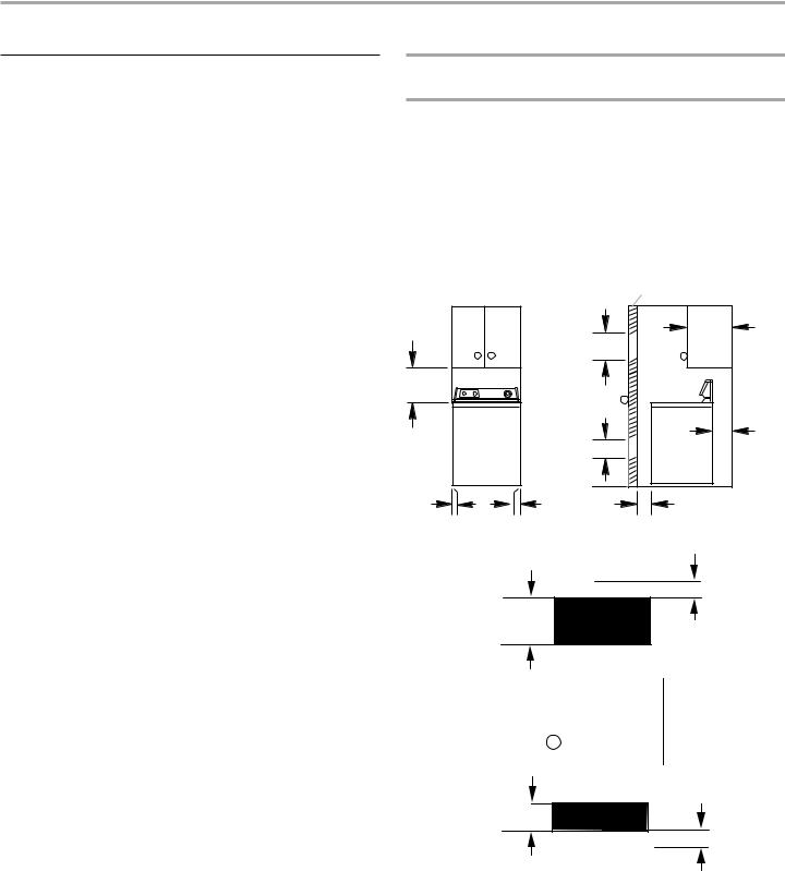
Recessed Area and Closet Installation Instructions
This washer may be installed in a recessed area or closet.
The installation spacing is in inches and is the minimum allowable. Additional spacing should be considered for ease of installation, servicing, and compliance with local codes and ordinances.
If closet door is installed, the minimum unobstructed air openings in the top and bottom are required. Louvered doors with equivalent air openings are acceptable.
Closet door
|
3.10 m2 |
356 mm |
|
|
(14") max. |
||
|
(48 in2)* |
|
|
432 mm |
|
|
|
(17") |
|
|
|
|
1.55 m2 |
102 mm |
|
|
(4") min. |
||
|
(24 in2)* |
|
|
0 mm |
0 mm |
|
|
(0") |
25 mm (1") min. |
||
(0") |
|||
|
|
Recessed front view |
Closet side view |
3.10 m2
48 in.2
(310(48cmin2))*
2 76 mm
3" (76(3")mm)
Front |
Closet |
View |
door |
|
|
763"mm
(76(3")mm)
24 in1..552 m2
(155 (24cm2in) 2)*
*Opening is the minimum for a closet door.
Louvered doors with equivalent air openings are acceptable.
νAdditional spacing should be considered for the ease of installation and servicing.
νAdditional clearances may be required for wall, door, and floor mouldings.
νAdditional spacing of 25 mm (1") on all sides of the washer is recommended to reduce noise transfer.
νCompanion spacing should also be considered.
4

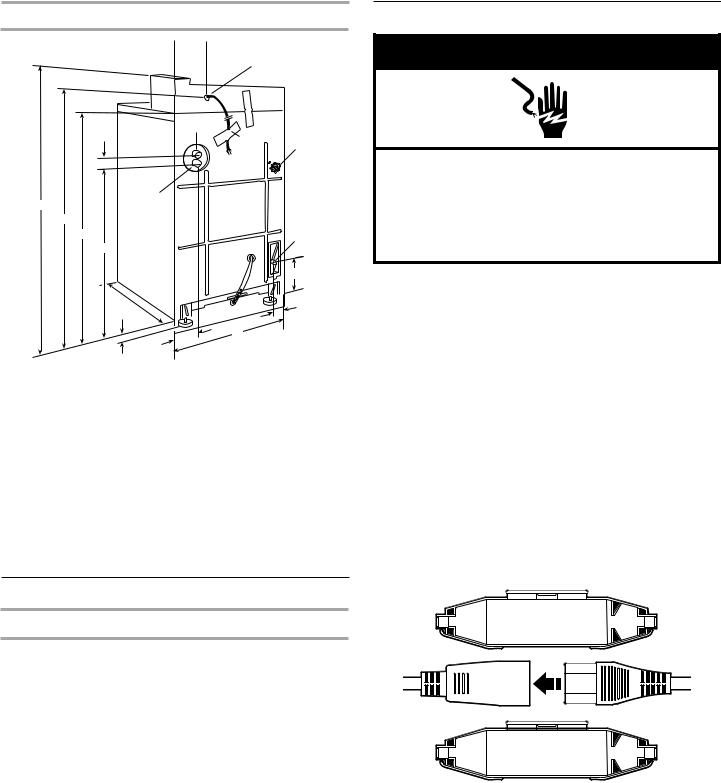
Product Dimensions
|
|
|
H |
|
|
|
|
|
I |
|
D |
|
Cold |
K |
|
|
|
||
|
|
|
|
|
|
|
|
|
J |
|
|
|
|
Hot |
|
A |
G |
|
|
|
|
|
|
|
|
B |
|
|
|
|
C |
|
|
O |
|
E |
|
|
|
|
|
|
|
|
|
|
|
|
P |
|
|
F |
|
|
|
|
|
M |
L |
|
|
|
|
|
|
|
N |
|
|
A. |
1.09 m (43") |
I. |
Power supply cord |
|
B. |
970 mm (381⁄8") |
J. |
Drain hose connector |
|
C. |
890 mm (35") |
K. |
Label |
|
D. |
38 mm (11⁄2") |
L. |
685 mm (27") |
|
E. |
705 mm (273⁄4") |
M. |
133 mm (51⁄4") |
|
F. |
650 mm (251⁄2") |
N. |
25 mm (1") |
|
G. |
Water inlets |
O. |
Water level switch and shaft |
|
H. |
180 mm (7") |
P. |
127 mm (5") |
|
Drain System
Standpipe Drain System
The standpipe drain requires a minimum diameter standpipe of 50 mm (2"). The minimum carry-away capacity can be no less than 64 L (17 gal.) per minute.
The top of the standpipe must be at least 990 mm (39") high and no higher than 1.83 m (72") from the bottom of the washer.
Electrical Requirements
νA 220–240 volt, 50 Hz., AC only, 10-amp, fused electric supply is required. A time-delay fuse or circuit breaker
is recommended. It is recommended that a separate circuit serving only this appliance be provided.
νThis washer is equipped with a power supply cord having an earthing plug. The plug should be accessible for disconnection from the supply.
νIf the supply cord is damaged, it must be replaced by the manufacturer, its service agent, or similarly qualified persons in order to avoid a hazard.
Using the universal cord included with this washer:
This washer is equipped with a universal cord with interchangeable mains plugs.
1. Select the appropriate mains plug assembly from those supplied and attach it to the mains cord connector.
2. Snap the 2 halves of the cord lock together over the connector to retain it in position.
5

Recommended Earthing Method
EARTHING INSTRUCTIONS
This washer must be earthed. In the event of a malfunction or breakdown, earthing will reduce the risk of electric shock by providing a path of least resistance for electric current. This washer is equipped with a cord having an equipment-earthing conductor and an earthing plug. The plug must be plugged into an appropriate outlet that is properly installed and earthed in accordance with all local codes and ordinances.
WARNING: Improper connection of the equipmentearthing conductor can result in a risk of electric shock. Check with a qualified electrician or serviceman if you are in doubt as to whether the appliance is properly earthed.
Do not modify the plug provided with the appliance – if it will not fit the outlet, have a proper outlet installed by a qualified electrician.
INSTALLATION INSTRUCTIONS
Remove Shipping Strap
 WARNING
Excessive Weight Hazard
Use two or more people to move and install washer. Failure to do so can result in back or other injury.
1.Remove tape that covers the shipping strap. Pull to completely remove the shipping strap with 2 cotter pins from the inside of the washer.
A
B
A.Shipping tape
B.Shipping strap
2.Pull firmly to remove the end of shipping strap from the back of the washer. The shipping strap plug must be completely removed from the washer for the self-leveling legs to be released.
Save the shipping strap for later use.
Connect the Hoses
Proper connection of the drain hose avoids damage to your floors due to water leakage. Read and follow these instructions.
Connect the inlet hose
1.The washer must be connected to the water taps using the new inlet hoses supplied with the washer. Do not re-use old hoses. Insert new flat washers (supplied) into each end of the inlet hoses. Firmly seat the washers in the couplings.
BA
A.Coupling
B.Washer
6

2. Attach hose to bottom inlet valve opening first.
A
B 


A.Cold water inlet valve
B.Hot water inlet valve
3.Attach second hose to top inlet. Tighten couplings by hand; then use pliers to make an additional two-thirds turn.
NOTE: Inlet valve threads are plastic. Do not strip or cross-thread.
Connect the drain hose
NOTE: Slide washer onto cardboard or hardboard before moving across floor.
1.Move washer close to final position.
2.Put “hook” end of drain hose into laundry tub or standpipe.
3.Estimate the length of drain hose needed when washer is in final position. Hose must be cut exactly to length so “hook” end is held tightly over edge of standpipe.
If drain hose is too long, cut straight end of hose. (Do not cut the “hook” shaped end of the drain hose.)
NOTE: Do not force excess length of drain hose down the standpipe. This could cause siphoning.
4. Place the hose clamp over the washer drain connector. Push the drain hose onto the washer connector. Use pliers to open clamp and slide clamp over drain hose. Check for good fit.
5.Measure and mark a point approximately 406 mm (16") from the plug end of the shipping strap. Cut shipping strap at this point.
406 mm (16")
6.Check that hose is not twisted or kinked and is securely in place.
Put “hook” end of drain hose into standpipe. Tightly wrap the shipping strap around the standpipe. Push plug into the nearest hole in the shipping strap.
Connect the inlet hoses to the water taps
1.Before attaching water inlet hoses to the water taps, run water through both taps into a bucket. This will get rid of particles in water lines that might clog hoses. Mark which is the hot water tap.
2.Install a black plastic tap adapter on each inlet hose.
3.Attach bottom hose (inlet marked “H”) to hot water taps. Tighten coupling to taps by hand.
4.Attach top hose (inlet marked “C”) to cold water taps. Tighten coupling to taps by hand.
5.Use pliers to make an additional two-thirds turn to each coupling.
Level the Washer
Install the front leveling feet
1.Stack two corner posts on top of each other. Tilt washer backward and insert corner posts 76 mm (3") in from one side of washer as shown. Repeat with other corner posts on other side of washer.
2.Use the leveling legs and nuts from parts package. Screw nut down to within 13 mm (1/2") from base.
A
B
C
A.13 mm (1/2")
B.Base
C.Nut
3.Insert legs into correct holes at each front corner of washer until nuts touch washer. Do not tighten nuts until the washer is leveled.
4.Tilt washer backward and
remove corner posts. Gently lower washer to floor.
5. Move washer to its permanent location. Remove cardboard or hardboard from under washer.
7
Level the washer |
|
Operating Tips |
|
|
|
1.Tilt washer forward, raising rear legs 25 mm (1") off of floor. To adjust rear self-leveling legs, gently lower washer to floor.
2. Check levelness of the washer by placing a carpenter’s level on top of the washer, first side to side; then front to back.
3.If washer is not level, adjust the front legs up or down. Make final check with level.
4. When washer is level, use a wrench to turn the nuts on front legs up tightly
against washer base. If nuts are not tight against washer base, the washer may vibrate.
Complete Installation
1.Check the electrical requirements. Be sure that you have the correct electrical supply and the recommended earthing method.
2.Check that all parts are now installed. If there is an extra part, go back through the steps to see which step was skipped.
3.Turn on water taps and check for leaks. Tighten couplings if there is leaking. Do not overtighten; this could cause damage to the taps.
4.Be sure you have all of your tools.
5.Check that the shipping strap was removed from the back of the washer and used to secure the drain hose. If entire strap is not removed, washer may vibrate and be noisy.
6.Plug power supply cord into an earthed outlet.
NOTE: On some models, during factory testing, the timer is advanced partially into the cycle, causing the start button to be depressed. Allow timer to advance to the end of the cycle. When the cycle is complete, the timer will reset and the start button will return to the start position. If the timer is not allowed to advance to the end of the first cycle and reset, the wash load will not be completed.
Checklist for washer operation
Check the following if the washer is not operating properly:
1.Power supply cord is plugged in.
2.Circuit breaker is not tripped or fuse is not blown.
3.Timer has been advanced to start of a cycle.
4.Water taps are turned on.
5.Inlet and drain hoses are not kinked.
6.Washer lid is closed.
7.Inlet valve can freeze if not protected from the weather.
8.Suds level. Excess suds will slow the spin and cause poor rinsing. Operate the washer through a complete cycle with no detergent. Use less detergent or a controlled suds type detergent in future loads.
If you need assistance:
Contact your authorized Maytag® Commercial Laundry distributor. To locate your authorized Maytag® Commercial Laundry distributor, or for web inquiries, visit www.MaytagCommercialLaundry.com.
When you call, you will need the washer model number and serial number. Both numbers can be found on the model/ serial-rating plate located under the lid.
8
Typical full load sizes
Load Type |
Loading |
Load Type |
Loading |
|
Suggestion |
|
Suggestion |
|
|
|
|
Mixed Load |
3 double sheets |
Heavy Work |
3 pair pants |
|
4 pillowcases |
Clothes |
3 shirts |
|
6 pair shorts |
|
1 coverall |
|
8 T-shirts |
|
4 pair jeans |
|
2 shirts |
|
1 overall |
|
2 blouses |
|
|
|
8 handkerchiefs |
|
|
|
|
|
|
Permanent |
2 double or |
Knits |
3 blouses |
Press |
1 king-size sheet |
|
4 slacks |
|
1 tablecloth |
|
6 shirts |
|
1 dress |
|
4 tops |
|
1 blouse |
|
4 dresses |
|
2 slacks |
|
|
|
3 shirts |
|
|
|
2 pillowcases |
|
|
|
|
|
|
Moving the washer to a new location
νRemove the front legs from the base of the washer.
νPlace both rear leveling legs in the upper position and tape securely.
νApply tape to the side and bottom of the cabinet near the rear.
νOpen washer lid and wedge a blanket between the tub ring and the cabinet top to restrict the tub movement.
Front legs
Rear legs |
Tape 2 sides. |

ELECTRONIC CONTROLS SETUP
BASIC OPERATION OF COMMERCIAL WASHER
νFor additional information, see www.MaytagCommercialLaundry.com.
νThis tech sheet is not valid for models prior to series MAT14.
IMPORTANT
Electrostatic Discharge (ESD)
Sensitive Electronics
ESD problems are present everywhere. ESD may damage or weaken the electronic control assembly. The new control assembly may appear to work well after repair is finished, but failure may occur at a later date due to ESD stress.
νUse an anti-static wrist strap. Connect wrist strap
to green ground connection point or unpainted metal in the appliance
-OR-
Touch your finger repeatedly to a green ground connection point or unpainted metal in the appliance.
νBefore removing the part from its package, touch the antistatic bag to a green ground connection point or unpainted metal in the appliance.
νAvoid touching electronic parts or terminal contacts; handle electronic control assembly by edges only.
νWhen repackaging failed electronic control assembly in antistatic bag, observe above instructions.
GENERAL USER INFORMATION
Blank display
This condition indicates the appliance is inoperative. Enter set-up mode to view diagnostic code.
“0 Minutes” showing in display
This condition indicates the appliance cannot be operated. Coins dropped or debit inputs during this condition will be stored in escrow but cannot be used until normal operation is restored by opening and closing the door. If a door switch fails, it must be replaced before normal operation can be restored.
Cold Start (initial first use)
Washer is programmed at the factory as follows:
ν11-minute wash period
ν1 rinse and 2 minutes of rinse agitation
ν$1.75 wash price (PD Models).
ν$0.00 wash price (PR Models).
Warm Start (after power failure)
After a delay of up to 8 seconds, the washer is restored to the state that existed at time of the power failure.
Free Cycles
This is established by setting the cycle price to zero. When this happens, “SELECT CYCLE” will appear rather than a cycle price.
Debit Card Ready
This washer is debit card “cable” ready. It will accept a variety of debit card systems, but does NOT come with a debit card reader. Refer to the debit card reader manufacturer for proper washer set-up. In models converted to a Generation 1 debit card system, debit pulses represent the equivalent of one coin (coin 1).
Display
After the washer has been installed and plugged in, the display will show “0 MINUTES.” Once the washer has been plugged in and the washer door opened and closed, the display will show the price. In washers set for free cycles, the display will flash “SELECT CYCLE.”
0 MINUTES
PRICE 2.00
9

CONTROL SET-UP PROCEDURES
IMPORTANT: Read all instructions before operating.
The lower fabric setting key pads and the digital display are used to set up the controls. The display can contain 4 numbers and/or letters and a decimal point. These are used to indicate the set-up codes and related code values available for use in programming the washer.
How to use the key pads to p;rogram the controls
1.The LOWER LEFT key pad is used to adjust the values associated with set-up codes. Pressing the key pad will increment the value. Rapid ajustment is possible by holding down the key pad.
2.The LOWER MIDDLE key pad will advance you through the set-up codes. Pressing the key pad will advance you to the next available set-up code. Holding down the key pad will automatically advance through the set-up codes at a rate of one (1) per second.
3.The LOWER RIGHT key pad is used to select or deselect options.
Start Operating Set-Up
νPD Models: Insert access door key, turn, and lift to remove access door.
νPR Models: Once the debit card reader is installed (according to the reader manufacturer’s instructions), the set-up mode can be entered by inserting a set-up card (supplied by the reader manufacturer) into the card slot. If a manual set-up card is not available, manual set-up mode can be entered
by removing connector AA1 on the circuit board.
IMPORTANT: The console must not be opened unless power is first removed from the washer. To access connector AA1:
gUnplug washer or disconnect power.
gOpen console, disconnect plug on AA1, close console.
gPlug in washer or reconnect power.
The washer is now in the set-up mode.
NOTE: The control does not need to be set up in order for the washer to operate. These procedures are to be followed only to customize the control as desired.
SET-UP CODES
νThe LOWER MIDDLE key pad will advance from code to code.
νThe LOWER LEFT key pad will change the code value.
νThe LOWER RIGHT key pad will select or deselect options.
FOR PR MODELS: The set-up codes are the same as for the PD models, except where noted.
The set-up code is indicated by the one or two left-hand characters. The set-up code value is indicated by the two or three right-hand characters.
CODE |
EXPLANATION |
|
|
6.07REGULAR CYCLE PRICE
6.07Represents the number of coins (coin 1); may adjust from 0–39. (See VALUE OF COIN 1.) Advance from 0–39 by pressing the LOWER LEFT key pad. Factory preset for 7 coins = $1.75.
PR MODELS ONLY: Factory preset for 0 coins.
g Press the LOWER MIDDLE key pad once to advance to next code.
10
|
CODE |
EXPLANATION |
||
|
|
|
|
|
7.1 1 |
WASH LENGTH |
|||
|
|
|
|
|
7.1 1 |
This is the number of minutes for WASH. |
|||
|
|
|
|
Choose from 8–20 minutes by pressing the LOWER |
|
|
|
|
LEFT key pad. |
|
|
|
|
|
g Press the LOWER MIDDLE key pad once to advance to next code.
8.2 1 RINSE CYCLES
8.2 1 This is the length and total number of rinses. Each
rinse agitation is 1–4 minutes, with a choice of 1 or 2 rinses. The middle digit is the length of rinse agitation and the right digit is the number of rinses.
The number is changed in the following sequence (11, 21, 31, 41, 12, 22, 32, 42) by pressing the LOWER LEFT key pad.
Press the LOWER MIDDLE key pad once to advance to next code.
The DELICATES & KNITS cycle has a fixed rinse agitation length of one minute.
gPress the LOWER MIDDLE key pad once to advance to next code.
9.00CYCLE COUNTER OPTION
This option is either SELECTED “ON” or NOT
SELECTED “OFF.”
9.00Not Selected “OFF.”
9.0C Selected “ON” and not able to be deselected.
Press the LOWER RIGHT key pad 3 consecutive times to select “ON.” Once selected “ON” it cannot be deselected.
g Press the LOWER MIDDLE key pad once to advance to next code.
1.00MONEY COUNTER OPTION
This option is either SELECTED “ON” or NOT
SELECTED “OFF.”
1.00Not Selected “OFF.”
1.0C Selected “ON.”
Press the LOWER RIGHT key pad 3 consecutive times to select “ON” and 3 consecutive times to remove (Not Selected “OFF.”) Counter resets by going from “OFF” to “ON.”
1. C 0 Selected “ON” and not able to be deselected.
To select “ON” and not able to be deselected, first select “ON,” then within two seconds press the LOWER RIGHT key pad twice, the LOWER LEFT key pad once, and exit the set-up mode.
g Press the LOWER MIDDLE key pad once to advance to next code.
2.00SPECIAL PRICING OPTION
This option is either SELECTED “ON” or NOT
SELECTED “OFF.”
2.00Not Selected “OFF.”
2.5P |
Selected “ON.” Press the LOWER RIGHT key pad |
||
|
|
|
once for this selection. |
If SPECIAL PRICING OPTION is selected, you have access to codes “3.” through “9.”.
g Press the LOWER MIDDLE key pad once to advance to next code.
OPTIONS TO USE IF SPECIAL PRICING IS SELECTED:
3.0 7 SPECIAL CYCLE PRICE
3.0 7 Represents the number of quarters (coin 1): may
adjust from 0–39. (See VALUE OF COIN 1.) Advance from 0–39 by pressing the LOWER LEFT key pad. Factory preset for 7 coins = $1.75.
PR MODELS ONLY: Factory preset for 0 coins.
g Press the LOWER MIDDLE key pad once to advance to next code.
CODE |
EXPLANATION |
|
|
|
OPTIONS TO USE IF SPECIAL PRICING IS SELECTED (cont.): |
5.00TIME-OF-DAY CLOCK, MINUTES
5.00This is the TIME-OF-DAY CLOCK, minute setting;
select 0–59 minutes by pressing the LOWER LEFT key pad.
gPress the LOWER MIDDLE key pad once to advance to next code.
6.00TIME-OF-DAY CLOCK, HOURS
NOTE: Uses military time or 24 hr. clock.
6.00This is the TIME-OF-DAY CLOCK, hour setting; select 0–23 hours by pressing the LOWER LEFT key pad.
gPress the LOWER MIDDLE key pad once to advance to next code.
7.00SPECIAL PRICE START HOUR
NOTE: Uses military time or 24 hr. clock.
7.00This is the start hour, 0–23 hours. Select START HOUR by pressing the LOWER LEFT key pad.
gPress the LOWER MIDDLE key pad once to advance to next code.
8.00SPECIAL PRICE STOP HOUR
NOTE: Uses military time or 24 hr. clock.
8.00This is the stop hour; 0–23 hours. Select STOP HOUR by pressing the LOWER LEFT key pad.
gPress the LOWER MIDDLE key pad once to advance to next code.
9.10SPECIAL PRICE DAY
9.10This represents the day of the week and whether special pricing is selected for that day. A number followed by “0” indicates no selection that particular day (9.10). A number followed by an “S” indicates selected for that day (9.1S).
Days of the week (1–7) can be chosen by pressing the LOWER LEFT key pad. Press LOWER LEFT key pad once to select special pricing for each day chosen.
When exiting setup code “9.”, the display must show current day of week:
DISPLAY |
DAY OF WEEK |
CODE (selected) |
|
10 |
Day 1 = Sunday |
1S |
|
20 |
Day 2 = Monday |
2S |
|
30 |
Day 3 = Tuesday |
3S |
|
40 |
Day 4 |
= Wednesday |
4S |
50 |
Day 5 |
= Thursday |
5S |
60 |
Day 6 |
= Friday |
6S |
70 |
Day 7 |
= Saturday |
7S |
g Press the LOWER MIDDLE key pad once to advance to next code.
A.00 VAULT VIEWING OPTION
This option is either SELECTED “ON” or NOT SELECTED “OFF.”
A.00 Not Selected “OFF.”
A.SC Selected “ON.” Press LOWER RIGHT key pad once for this selection. When selected, the money and/or cycle counts will be viewable (if counting is selected) when the coin box is removed.
g Press the LOWER MIDDLE key pad once to advance to next code.
6.05VALUE OF COIN 1
6.05This represents the value of coin 1 in number of coins: 05 = $0.25.
By pressing the LOWER LEFT key pad, you have the option of 1–199 coins.
g Press the LOWER MIDDLE key pad once to advance to next code.
|
CODE |
EXPLANATION |
||
|
|
|
|
|
|
C.20 |
VALUE OF COIN 2 |
||
|
|
|
|
|
|
C.20 |
This represents the value of coin 2 in number of |
||
|
|
|
|
coins: 20 = $1.00. |
|
|
|
|
PR MODELS: Factory preset for $0.25. |
|
|
|
|
By pressing the PERMANENT PRESS key pad, you |
|
|
|
|
have the option of 1–199 coins. |
|
|
|
|
|
g Press the LOWER MIDDLE key pad once to advance to next code.
8.00COIN SLIDE OPTION
This option is either SELECTED “ON” or NOT SELECTED “OFF.”
8.00Not Selected “OFF.”
8.CS |
Selected “ON.” Press the LOWER RIGHT key pad |
||
|
|
|
3 consecutive times for this selection. |
|
|
|
When coin slide mode is selected, set “b.” equal to |
|
|
|
value of slide in coins. Set step 6 (regular cycle price) |
|
|
|
and step 3 (special cycle price) to number |
|
|
|
of slide operations. |
|
|
|
NOTE: If the installer sets up “CS” on a coin drop |
|
|
|
model, it will not register coins. |
g Press the LOWER MIDDLE key pad once to advance to next code.
E.00 ADD COINS OPTION
This option is either SELECTED “ON” or NOT SELECTED “OFF.” This option causes the customer display to show the number of coins (coin 1) to enter, rather than the dollars-and-cents amount.
E.00 Not Selected “OFF.”
E.AC Selected “ON.” Press the LOWER RIGHT key pad 3 consecutive times for this selection.
g Press the LOWER MIDDLE key pad once to advance to next code.
F.00 ENHANCED PRICING OPTION
F.00 Not Selected “OFF.”
F.CP Cycle-Based pricing enables. This option allows configuration of different prices for cold, warm, and hot water cycles. Press the LOWER RIGHT key pad for this selection.
F.S u Super Cycle pricing enabled. This option allows customers to upgrade cycles by depositing extra money. Set-up codes “H.” and “h.” will be displayed only when this option is enabled. Press the LOWER RIGHT key pad for this selection.
g Press the LOWER MIDDLE key pad once to advance to next code.
H.0 1 SUPER CYCLE UPGRADE PRICE
(Skipped unless Super Cycle pricing is enabled.)
H.0 1 This represents the number of coin 1 required to upgrade a base cycle to a super cycle. Advance from 0–39 by pressing the LOWER LEFT key pad.
g Press the LOWER MIDDLE key pad once to advance to next code.
h.0 1 SUPER CYCLE TYPE
(Skipped unless Super Cycle pricing is enabled.)
h.0 1 This represents the Super Cycle upgrade option. Press the LOWER LEFT key pad to step through upgrade options 1 through 3 as follows:
01 – enhanced wash, extra 3 minutes of wash tumble in addition to the programmed wash time.
02 – extra rinse for all cycles.
03 – both 01 and 02.
g Press the LOWER MIDDLE key pad once to advance to next code.
11

CODE |
EXPLANATION |
|
|
|
COIN/DEBIT OPTION |
|
|
|
Both coin and debit selected. |
|
|
|
Coins selected, debit disabled. Press LOWER RIGHT |
|
key pad for this selection. |
|
|
|
Debit Card selected, coins disabled. Press LOWER |
|
RIGHT key pad for this selection. |
|
|
|
Enhanced Debit is self-selected when a Generation |
|
2 card reader is installed in the washer. The “Ed” |
|
option cannot be manually selected or deselected. |
g Press the LOWER MIDDLE key pad once to advance to next code.
PRICE SUPPRESSION OPTION
This option causes the customer display to show “ADD” or “AVAILABLE” rather than the amount of money to add. (Used mainly in debit installations.)
Not Selected “OFF.”
Selected “ON.” Press the LOWER RIGHT key pad once for this selection.
g Press the LOWER MIDDLE key pad once to advance to next code.
CLEAR ESCROW OPTION
When selected,money held in escrow for 30 minutes without further escrow or cycle activity will be cleared.
Selected “ON.”
Not selected “OFF.” Press the LOWER RIGHT key pad once to deselect this selection.
g Press the LOWER MIDDLE key pad once to advance to next code.
PENNY INCREMENT OFFSET
This represents the penny increment price offset used in Generation 2 (Enhanced Debit) PR models. Choose from 0–4 pennies by pressing the LOWER LEFT key pad.
g Press the LOWER MIDDLE key pad once to advance to next code.
If cycle counter (9.0C) is selected, the following is true: |
|
||
100 |
Represents the number of cycles in HUNDREDS. |
1 02 |
= 200 |
200 |
Represents the number of cycles in ONES. |
2 25 |
= 25 |
|
|
|
|
|
TOTAL CYCLES |
= 225 |
|
This is “VIEW ONLY” and cannot be cleared.
Press the LOWER MIDDLE key pad once to advance to next code.
If money counter (1.0C or 1.C0) is selected, the following is true:
300 |
Currency amount in HUNDREDS. |
3 01 |
= 100.00 |
||
400 |
Currency amount in ONES. |
4 68 |
= |
68.00 |
|
500 |
Currency amount of CENTS. |
5 75 |
= |
.75 |
|
|
|
|
|
|
|
|
|
TOTAL |
= 168.75 |
||
END OF SET-UP PROCEDURES
EXIT FROM SET-UP MODE
νPD Models: Reinstall access door.
νPR Models:
gUnplug washer or disconnect power.
gOpen console, reinsert plug into AA1, close console.
gPlug in washer or reconnect power.
Europe
EU - DECLARATION OF CONFORMITY
CE - DECLARATION DE CONFORMITE
BAUKNECHT HAUSGERÄTE GmbH, D-73614 Schorndorf representing (représentant): WHIRLPOOL EUROPE S.r.l I-21025 COMERIO
declare under our sole responsibility that the product déclarons sous notre propre responsabilité que le produit
washing machine Maytag MAT14PD AGW
(machine à laver le linge):
to which this declaration relates is in conformity with the following standard(s) or other normative document(s)
auquel se référe cette déclaration est conforme aux normes suivantes ou autres documents normatifs
EN 60335-1:2002+A1+A2+A11+A12+A13
EN 60335-2-7:2003+A1+A2
EN 62233:2008
EN 61770:2009
EN 55014-1:2006+A1:2009
EN 55014-2:1997+Corr.1997+A1:2001+A2:2008
EN 61000-3-2:2006+A1:2009+A1:2009
EN 61000-3-11:2000
following the provisions of Directive(s): suivant les prévisions des Directives:
2006/95/EC LOW VOLTAGE DIRECTIVE (CEE Directive Basse Tension)
2004/108/EC ELECTROMAGNETIC COMPATIBILITY DIRECTIVE (CEE Directive Compatibilité Electro-magnétique)
|
represented by |
|
Schorndorf, 15.11.2011 |
Franz Hartmann |
Karl-Dieter Klingenstein |
Place and date: |
Director PDC FC EMEA |
Product Approval |
lieu et date |
|
GPO, Schorndorf |
|
Name and signature of aurthorised person |
|
Basic Type: MAT14PD AGW |
Nom et signature de la personne autorisée |
|
12

MAYTAG® COMMERCIAL SINGLE-LOADANDVENDED
MULTI-LOADWASHERAND DRYER
WARRANTY
LIMITED WARRANTY ON PARTS
For the first five years from the date of purchase, when this commercial appliance is installed, maintained and operated according to the instructions attached to or furnished with the product, Maytag brand of Whirlpool Corporation (thereafter “Maytag”) will pay for factory specified parts or original equipment manufacturer parts to correct defects in materials or workmanship. Proof of original purchase date is required to obtain service under this warranty.
ITEMS MAYTAG WILL NOT PAY FOR
1.All other costs including labor, transportation, or custom duties.
2.Service calls to correct the installation of your commercial appliance, to instruct you how to use your commercial appliance, to replace or repair fuses, or to correct external wiring or plumbing.
3.Repairs when your commercial appliance is used for other than normal, commercial use.
4.Damage resulting from improper handling of product during delivery, theft, accident, alteration, misuse, abuse, fire, flood, acts of God, improper installation, installation not in accordance with local electrical or plumbing codes, or use of products not approved by Maytag.
5.Pickup and Delivery. This commercial appliance is designed to be repaired on location.
6.Repairs to parts or systems resulting from unauthorized modifications made to the commercial appliance.
7.The removal and reinstallation of your commercial appliance if it is installed in an inaccessible location or is not installed in accordance with published installation instructions.
8.Chemical damage is excluded from all warranty coverage.
9.Changes to the building, room, or location needed in order to make the commercial appliance operate correctly.
10.Repairs made by a non-Whirlpool authorized service technician.
DISCLAIMER OF IMPLIED WARRANTIES; LIMITATIONS OF REMEDIES
CUSTOMER'S SOLE AND EXCLUSIVE REMEDY UNDER THIS LIMITED WARRANTY SHALL BE PRODUCT REPAIR AS PROVIDED HEREIN. IMPLIED WARRANTIES, INCLUDING WARRANTIES OF MERCHANTABILITY OR FITNESS FOR A PARTICULAR PURPOSE, ARE LIMITED TO ONE YEAR OR THE SHORTEST PERIOD ALLOWED BY LAW. WHIRLPOOL SHALL NOT BE LIABLE FOR INCIDENTAL OR CONSEQUENTIAL DAMAGES. SOME STATES AND PROVINCES DO NOT ALLOW THE EXCLUSION OR LIMITATION OF INCIDENTAL OR CONSEQUENTIAL DAMAGES, OR LIMITATIONS ON THE DURATION OF IMPLIED WARRANTIES OF MERCHANTABILITY OR FITNESS, SO THESE EXCLUSIONS OR LIMITATIONS MAY NOT APPLY TO YOU. THIS WARRANTY GIVES YOU SPECIFIC LEGAL RIGHTS AND YOU MAY ALSO HAVE OTHER RIGHTS, WHICH VARY FROM STATE TO STATE OR PROVINCE TO PROVINCE.
If you need service, please contact your authorized Maytag® Commercial Laundry distributor. To locate your authorized Maytag® Commercial Laundry distributor, or for web inquiries, visit www.MaytagCommercialLaundry.com.
3/10
For written correspondence:
Maytag® Commercial Laundry Service Department
2000 M-63 North
Benton Harbor, Michigan 49022 USA
13

SECURITE DU LAVE-LINGE
ÉLIMINATION DU LAVE-LINGE
14
EXIGENCES D’INSTALLATION
Outillage et pièces
Rassembler les outils et pièces nécessaires avant d’entreprendre l’installation.
Outils nécessaires
νNiveau
νCouteau utilitaire
νCiseaux
νClé à mollette de 200 mm (8") ou 250 mm (10")
Pièces fournies
νTournevis à lame plate
νPince
νSeau
Retirer les pièces du lave-linge. Vérifier la présence de toutes les pièces.
ν 1 bride de fixation |
ν 2 pieds de nivellement |
|
ν 2 tuyaux d’arrivée d’eau |
avant avec écrous |
|
ν 4 rondelles plates de |
ν 1 tuyau de vidange |
|
tuyau d’arrivée d’eau |
ν Adaptateur de tuyau |
|
|
|
|
Spécifications |
Capacité de |
|
techniques : |
vêtements : |
|
|
|
|
220 |
à 240 V, 50 Hz AC |
MAT14PD : 5,9 kg Max. |
|
|
|
650 |
Watts |
|
|
|
|
|
|
|
Exigences d’emplacement
IMPORTANT : Ne pas installer ou remiser le lave-linge dans un endroit où il sera exposé aux intempéries. Ne pas remiser ou faire fonctionner le lave-linge à des températures inférieures ou égales à 0°C (32°F). Une quantité d'eau peut demeurer dans le lave-linge et causer des dommages à des températures basses.
C’est à l’utilisateur qu’incombe la responsabilité de réaliser une installation correcte.
Il vous faudra :
νUn chauffe-eau pour fournir de l’eau à 60°C (140°F) au lave-linge.
νUne prise électrique reliée à la terre située à moins de 1,2 m (4 pi) de la prise du cordon électrique se trouvant à l’arrière du lave-linge. Voir “Spécifications électriques”.
νDes robinets d’eau chaude et d’eau froide situés à 1,2 m (4 pi) ou moins de l’arrière du lave-linge, et une pression d’eau
de 69 à 690 kPa (10 à 100 lb/po2). Lorsque la pression d’alimentation à l’entrée du bâtiment est supérieure
à690 kPa (100 lb/po2), on devrait installer une vanne de réduction de la pression pour éviter une éventuelle détérioration de la vanne de mixage du lave-linge.
νUn plancher de niveau ayant une pente maximale de 25 mm (1") sous l’ensemble du lave-linge.
νUn plancher robuste pour supporter le lave-linge dont le poids total (lave-linge, eau et charge) est de 143 kg (315 lb).
νUne colonne montante d’au moins 300 mm (12") destinée
àfournir un coussin d’air et à empêcher l’émission de bruit
et la détérioration des électrovannes lors de l’installation d’un seul lave-linge.
νUn égout au plancher doit être installé sous le module de la cloison. Les coffrages préfabriqués équipés de prises électriques, de lignes d’arrivée d’eau et conduites
d’évacuation doivent être utilisés seulement là où les codes locaux l’autorisent.
REMARQUE : On peut accéder à la zone avant de la pompe en retirant les vis de sécurité No. T20 TORX® † puis en retirant le panneau avant.
®† Torx est une marque déposée de Saturn Fasteners, Inc.
Instructions d’installation dans un encastrement ou un placard
Ce lave-linge peut être installé dans un encastrement ou un placard.
Les dimensions d’installation illustrées sont en centimètres et constituent le minimum applicable. Un espace supplémentaire peut être nécessaire pour faciliter l’installation, l’entretien et pour observer les codes et règlements locaux en vigueur.
Si une porte de placard est installée, des ouvertures d’évacuation de l’air minimales sont nécessaires dans les parties supérieure et inférieure. Les portes à claire-voie offrant des ouvertures équivalentes sont acceptables.
Porte du placard
|
3,10 m2 |
356 mm |
|
|
(14") max. |
||
|
(48 in2)* |
|
|
432 mm |
|
|
|
(17") |
|
|
|
|
1,55 m2 |
102 mm |
|
|
(4") min. |
||
|
(24 in2)* |
|
|
0 mm |
0 mm |
|
|
(0") |
25 mm (1") min. |
||
(0") |
|||
|
|
Vue encastrée de face |
Vue latérale |
du placard |
du placard |
3,10 m2
48 in.2
(310(48cmin2))*
2 76 mm
3" (76(3")mm)
Vue de |
|
|
|
Clos t |
|
Front |
|
|
face |
|
Porte |
View |
|
door |
|
|
du placard |
|
|
|
763"mm
(76(3")mm)
24 in1,55.2 m2
(155 (24cm2in) 2)*
*Dimension minimale pour une porte de placard. Les portes à claire-voie offrant des ouvertures équivalentes sont acceptables.
νUn espace supplémentaire peut être nécessaire pour faciliter l’installation et l’entretien.
νUn espace supplémentaire peut être requis pour les moulures de porte et de plancher et pour les plinthes.
νUn espace supplémentaire de 25 mm (1 po) de tous les côtés du lave-linge est recommandé pour réduire le transfert du bruit.
νIl faut aussi prendre en compte l’espace requis entre
les appareils voisins. |
15 |
Dimensions du produit
D
A
B
C
E
F
N
A.1,09 m (43 po)
B.970 mm (381⁄8 po)
C.890 mm (35 po)
D.38 mm (11⁄2 po)
E.705 mm (273⁄4 po)
F.650 mm (251⁄2 po)
G.Arrivées d’eau
H.180 mm (7 po)
 H
H 
I
Froid
K
J
 Chaud
Chaud
G
O
P
M |
L |
|
I.Cordon d’alimentation électrique
J.Connecteur du tuyau de vidange
K.Étiquette
L.685 mm (27 po)
M.133 mm (51⁄4 po)
N.25 mm (1 po)
O.Commutateur du niveau d’eau et tige de réglage
P.127 mm (5 po)
Système de vidange
Système de vidange avec tuyau de rejet à l’égout
Le système de rejet à l’égout nécessite un tuyau de diamètre minimum de 50 mm (2 po). La capacité minimum de vidange ne peut pas être inférieure à 64 L (17 gal.) par minute.
Le sommet du tuyau de rejet à l’égout doit être au moins
à 990 mm (39 po) de hauteur et au maximum à 1,83 m (72 po) de la base du lave-linge.
Spécifications électriques
 AVERTISSEMENT
Risque de choc électrique Brancher sur une prise reliée à la terre.
Ne pas utiliser un câble de rallonge ou un adaptateur.
Le non-respect de ces instructions peut causer un décès, un incendie ou un choc électrique.
νL’appareil doit être alimenté par un circuit de 220-240 V, CA seulement, 50 Hz, protégé par un fusible. On recommande d’utiliser un fusible ou un disjoncteur temporisé. Il est recommandé de raccorder le lave-linge sur un circuit distinct exclusif à cet appareil.
νCe lave-linge comporte un cordon d’alimentation électrique pour liaison à la terre. La prise doit être accessible pour pouvoir déconnecter l’appareil de l’alimentation électrique.
νSi le cordon d’alimentation est endommagé, il doit être remplacé par le fabricant, son agent de service ou toute autre personne qualifiée afin d’éviter tout danger.
À l’aide du cordon universel d’alimentation électrique fourni avec ce lave-linge :
Ce lave-linge comporte un cordon universel avec des prises principales interchangeables.
1. Sélectionner la prise principale appropriée parmi les prises fournies et la fixer au connecteur du cordon de câblage principal.
2. Enclencher les deux moitiés du système de retenue
du cordon sur le connecteur pour le maintenir en place.
16
 Loading...