

Maxdata 9000-2R user manual

Product Guide
MAXDATA PLATINUM 9000-2R Server System

2 3MAXDATA PLATINUM 90002R Server System

Contents
Important Safety Information 11
Important Safety Instructions................................................................................................................11
Wichtige Sicherheitshinweise ...............................................................................................................11
Important Safety Instructions Consignes de sécurité ...........................................................................11
Instrucciones de seguridad importantes ............................................................................................... 11
Regulatory and Certication Information ..............................................................................................11
Product Regulatory Compliance....................................................................................................... 11
Product Safety Compliance.............................................................................................................. 11
Product EMC Compliance ...............................................................................................................12
Product Regulatory Compliance Markings.......................................................................................12
Electromagnetic Compatibility Notices .................................................................................................12
Europe (CE Declaration of Conformity) ............................................................................................12
Conventions .........................................................................................................................................12
1 System Description 13
External Chassis Features .....................................................................................................................15
Chassis Front....................................................................................................................................15
Front Panel .......................................................................................................................................16
Peripheral Bay ..................................................................................................................................17
Hot-swap Hard Drive Carrier ............................................................................................................18
Removable Media Drive Bay............................................................................................................19
Power Supply Bay ........................................................................................................................... 20
Chassis Rear.................................................................................................................................... 22
Internal Chassis Features ..................................................................................................................... 23
Electronics Bay................................................................................................................................ 23
Cooling Subsystem ......................................................................................................................... 25
Power Subsystem........................................................................................................................... 27
Power Supply Modules ................................................................................................................... 27
Redundant AC Power Source Operation......................................................................................... 28
Processor Power Pods.................................................................................................................... 28
2 Board Set Description 29
Main Board ............................................................................................................................................31
Processor Sockets .......................................................................................................................... 33
Memory Subsystem........................................................................................................................ 33
SCSI Controller................................................................................................................................ 34
Network Interface Controller........................................................................................................... 34
IDE Controller.................................................................................................................................. 35
Baseboard Management Controller (BMC)..................................................................................... 35
The following is a list of the major functions of the BMC: .............................................................. 35
PCI Riser Board .................................................................................................................................... 36
SCSI Backplane Board.......................................................................................................................... 37
QLogic GEM359 SCSI Hot-swap Controller ................................................................................... 38
Front Panel Board................................................................................................................................. 39
Front Panel Board Functional Blocks............................................................................................... 39
3 Conguration Software and Utilities 41
Utilities / Drivers on Resource CD.........................................................................................................41
Running Software Utilities Directly from the Resource CD .............................................................41
Power-on Sequence and Power-on Self-Test (POST) ..................................................................... 42
Extensible Firmware Interface Boot Manager ..................................................................................... 42
The Extensible Firmware Interface (EFI) Shell ..................................................................................... 45

4 Contents
5MAXDATA PLATINUM 90002R Server System
CMOS Clear .....................................................................................................................................47
BIOS Recovery Mode ..................................................................................................................... 48
BIOS Setup........................................................................................................................................... 49
Starting Setup ................................................................................................................................. 49
Recording Your Setup Settings ....................................................................................................... 49
Navigating Setup Utility Screens..................................................................................................... 49
Setup Screens................................................................................................................................. 50
Main ................................................................................................................................................ 50
Advanced .........................................................................................................................................51
Security ........................................................................................................................................... 52
System Management...................................................................................................................... 52
Exit .................................................................................................................................................. 54
LSI Logic SCSI Utility ........................................................................................................................... 55
Launching the LSI SCSI Utility ........................................................................................................ 55
Running the LSI SCSI Utility ........................................................................................................... 55
System Maintenance Utility ................................................................................................................. 57
Remote Keyboard Navigation.......................................................................................................... 58
Local Keyboard Navigation .............................................................................................................. 58
About Box Information .................................................................................................................... 59
Server Discovery ............................................................................................................................. 60
Remote SMU Application................................................................................................................ 60
Local SMU Application.................................................................................................................... 62
Running from CD............................................................................................................................. 62
Running from the System Partition................................................................................................. 63
Shutdown SMU Application............................................................................................................ 63
Server Management Conguration Task......................................................................................... 63
LAN Channel Conguration Sub-task ............................................................................................. 64
Default LAN Conguration Settings Set by the SMU ..................................................................... 65
Access Mode .................................................................................................................................. 65
Privilege Level Limit ........................................................................................................................ 65
Enable DHCP................................................................................................................................... 65
Host IP Address .............................................................................................................................. 66
Subnet Mask ................................................................................................................................... 66
Default Gateway IP Address ........................................................................................................... 66
Default Gateway MAC Address ...................................................................................................... 66
Automatically Resolve Default Gateway MAC Address.................................................................. 66
Backup Gateway IP Address........................................................................................................... 66
Backup Gateway MAC Address...................................................................................................... 66
Automatically Resolve Backup Gateway MAC Address ................................................................. 67
LAN Alert Conguration.................................................................................................................. 67
Enable LAN Alerting........................................................................................................................ 67
SNMP Community String................................................................................................................ 67
Alert Settings .................................................................................................................................. 68
New, Edit, and Delete Buttons........................................................................................................ 68
New/Edit LAN Alert ........................................................................................................................ 68
Destination IP Address.................................................................................................................... 69
Destination MAC Address............................................................................................................... 69
Automatically Resolve Destination MAC Address .......................................................................... 69
Number of Retries........................................................................................................................... 69
Retry Interval................................................................................................................................... 69
Enable Alert Acknowledge.............................................................................................................. 69
Use Default Gateway ...................................................................................................................... 69
Serial Over LAN Conguration ........................................................................................................70
Enable Serial Over LAN....................................................................................................................70
SOL Privilege Level ..........................................................................................................................70
Number of Retries............................................................................................................................70

5MAXDATA PLATINUM 90002R Server System
Retry Interval....................................................................................................................................70
Baud Rate.........................................................................................................................................70
User Conguration Sub-task ............................................................................................................71
Enable User..................................................................................................................................... 72
Enter Username .............................................................................................................................. 72
Clear Password ............................................................................................................................... 72
Enter/Verify New Password ............................................................................................................ 72
User Privilege Level for LAN Channels ........................................................................................... 73
User Privilege Level for Serial/Modem Channel ............................................................................. 73
Platform Event Filtering (PEF) Sub-task .......................................................................................... 73
Enable PEF .......................................................................................................................................74
Enable SEL Event Messages for PEF Actions .................................................................................74
PEF Startup Delay ............................................................................................................................74
Alert Startup Delay...........................................................................................................................74
PEF Action Global Settings ..............................................................................................................74
Event Filter Settings.........................................................................................................................74
Edit Event Filter Settings................................................................................................................. 75
Enable Event Filter .......................................................................................................................... 75
Enable Alerts ...................................................................................................................................76
Policy Number Associated With This Event Filter............................................................................76
Chassis Action Associated With This Event Filter............................................................................76
Congure Policies Button.................................................................................................................76
Alert Policy Table .............................................................................................................................76
Edit Alert Policy Entry ..................................................................................................................... 78
Enable Policy Entry.......................................................................................................................... 78
Policy Number................................................................................................................................. 78
Policy Type ...................................................................................................................................... 78
Select the Destination..................................................................................................................... 79
Serial/Modem Channel Conguration Sub-task .............................................................................. 79
Default Serial/Modem Conguration Settings Set By the SMU ..................................................... 80
Connection Mode............................................................................................................................ 80
Access Mode ................................................................................................................................. 80
Privilege Level Limit .........................................................................................................................81
IPMI Messaging Communication Settings ......................................................................................81
Modem Mode Conguration............................................................................................................81
Modem Init String ............................................................................................................................81
Modem Escape Sequence.............................................................................................................. 82
Hang-up Sequence.......................................................................................................................... 82
Dial Command................................................................................................................................. 82
Ring Duration .................................................................................................................................. 82
Ring Dead Time............................................................................................................................... 82
Destination Dial Strings .................................................................................................................. 83
New, Edit, and Delete Buttons........................................................................................................ 83
New/Edit Dial String........................................................................................................................ 84
Destination Dial String..................................................................................................................... 84
Page Destination Conguration....................................................................................................... 85
Enable Paging.................................................................................................................................. 85
Page Blackout Interval..................................................................................................................... 86
Call Retry Interval ............................................................................................................................ 86
Edit Page Destination...................................................................................................................... 86
Dial String........................................................................................................................................ 86
Flow Control.................................................................................................................................... 86
Baud Rate........................................................................................................................................ 86
Stop Bits.......................................................................................................................................... 86
Data Bits.......................................................................................................................................... 87
Parity ............................................................................................................................................... 87

6 Contents
7MAXDATA PLATINUM 90002R Server System
Call Retries ...................................................................................................................................... 87
Terminal Mode Conguration.......................................................................................................... 87
Enable Terminal Mode .................................................................................................................... 87
Enable Line Editing.......................................................................................................................... 88
Delete Control ................................................................................................................................. 88
Turn BMC Echo of Received Characters On ................................................................................... 88
Enable Handshake When BMC Ready To Receive Another Message............................................ 88
Newline Output Sequence (BMC to console)................................................................................. 88
Newline Input Sequence (console to BMC).................................................................................... 88
Power Conguration Sub-task ........................................................................................................ 89
Chassis stays powered off when power is applied......................................................................... 89
Power is restored to the state that was in effect when power was lost ........................................ 89
Chassis always powers up when power is restored....................................................................... 89
SEL Viewer...................................................................................................................................... 90
Viewing Events in the SEL ...............................................................................................................91
Home Button................................................................................................................................... 92
End Button ...................................................................................................................................... 92
Previous Button............................................................................................................................... 92
Next Button..................................................................................................................................... 92
<<More Button ............................................................................................................................... 92
More>> Button ............................................................................................................................... 92
Viewing Single Events..................................................................................................................... 92
Sorting the SEL ............................................................................................................................... 92
Save Log Button.............................................................................................................................. 93
Open Log Button............................................................................................................................. 93
Clear SEL Button............................................................................................................................. 93
Properties Button ............................................................................................................................ 93
Reload Button ................................................................................................................................. 93
Display as Hex Button..................................................................................................................... 94
Display as Text Button .................................................................................................................... 94
SDR Viewer..................................................................................................................................... 94
Viewing SDRs ................................................................................................................................. 95
Close Button ................................................................................................................................... 96
Previous Button............................................................................................................................... 96
Next Button..................................................................................................................................... 96
Save To File Button ......................................................................................................................... 96
Open File Button ............................................................................................................................. 96
Properties Button ............................................................................................................................ 96
Reload Button ................................................................................................................................. 96
FRU Viewer ..................................................................................................................................... 96
Viewing FRUs.................................................................................................................................. 97
Save To File Button ......................................................................................................................... 98
Open File Button ............................................................................................................................. 98
Properties Button ............................................................................................................................ 98
Reload Button ................................................................................................................................. 99
Help Button ..................................................................................................................................... 99
Task Error Handling ......................................................................................................................... 99
Data Entry Errors............................................................................................................................. 99
Internal Errors For Which a View Can Be Generated ...................................................................... 99
Data Corruption Errors that the SMU Application can Handle ........................................................ 99
Internal Errors For Which a View Cannot Be Generated ................................................................. 99
Help............................................................................................................................................... 100
Help for the Remote SMU Application.......................................................................................... 100
ISM Front-end Help....................................................................................................................... 100
SMU Table of Contents Help ........................................................................................................ 100
Help for the Local SMU Application...............................................................................................101

7MAXDATA PLATINUM 90002R Server System
EFI Platform Diagnostic Tests .............................................................................................................102
Starting the Application..................................................................................................................102
Understanding the General User Interface ....................................................................................102
Understanding Basic Testing..........................................................................................................103
Enabling Tests For Execution .........................................................................................................103
Setting Test Options ......................................................................................................................103
Interpreting Results........................................................................................................................103
Help On Individual Tests ................................................................................................................103
Viewing System Information......................................................................................................... 104
Viewing the Test Log .................................................................................................................... 104
EFI Service Partition ........................................................................................................................... 104
Service Partition Requirements .................................................................................................... 104
Installing Service Partition Files .................................................................................................... 104
Installation Requirements.............................................................................................................. 104
Installing the Files...........................................................................................................................105
Booting from the Service Partition.................................................................................................105
Locally ............................................................................................................................................105
Console Redirection ........................................................................................................................... 106
Operation ...................................................................................................................................... 106
Keystroke Mappings.......................................................................................................................107
Limitations..................................................................................................................................... 109
Server Management Interface ...................................................................................................... 109
Sample Setup for Console Redirection ......................................................................................... 109
Server Conguration ..................................................................................................................... 109
Console Conguration.................................................................................................................... 110
Terminal Mode .................................................................................................................................... 110
Setup and Conguration................................................................................................................. 110
Connection Mechanism .................................................................................................................110
Hardware Setup .............................................................................................................................111
Conguration Using System Maintenance Utility (SMU) ............................................................... 111
Serial Channel Conguration .......................................................................................................... 111
Sample Setup for Terminal Mode ..................................................................................................111
Server Conguration ......................................................................................................................112
Console Conguration.................................................................................................................... 113
Logging Into the Terminal Mode Session ...................................................................................... 113
User Conguration .........................................................................................................................113
Security Information....................................................................................................................... 113
Terminal Mode Commands............................................................................................................ 114
Input Restrictions .......................................................................................................................... 114
Switching between Console Redirection and Terminal Mode ....................................................... 114
Syntax ............................................................................................................................................ 114
Command Length .......................................................................................................................... 114
Character Support ..........................................................................................................................114
Special Character Handling - <ESC> character.............................................................................. 114
Special Character Handling - <DEL> or <BKSP> character........................................................... 114
Special Character Handling - Line Continuation character..............................................................114
Special Character Handling - Illegal characters...............................................................................114
Hex-ASCII Command Format......................................................................................................... 115
Text Command Format ..................................................................................................................115
Terminal Mode IPMI Message Bridging ........................................................................................ 116
Shutting Down the Server...................................................................................................................123

8 Contents
9MAXDATA PLATINUM 90002R Server System
4 Technical Reference 125
System Interconnection ......................................................................................................................126
User-Accessible Interconnects............................................................................................................127
Serial Port.......................................................................................................................................127
Video Port ......................................................................................................................................128
Universal Serial Bus (USB) Interface..............................................................................................128
Ethernet Connector........................................................................................................................129
Ultra320 SCA-2 HDD Connector....................................................................................................131
External Ultra320 SCSI Connector.................................................................................................132
AC Power Input..............................................................................................................................133
Jumper Information.............................................................................................................................133
Changing Jumper Settings.............................................................................................................133
Conguring Main Board Jumpers ................................................................................................. 134
POST Error Codes and Messages 135
North and South Port 80/81 Cards......................................................................................................135
POST Codes........................................................................................................................................135
POST Codes Module Map .............................................................................................................135
Specic POST Code Modules........................................................................................................138
SAL-A Module ................................................................................................................................138
SAL-B Module ................................................................................................................................140
SAL-F Module ............................................................................................................................... 143
IA-32 Module ................................................................................................................................ 144
Recovery Port 80 Codes ............................................................................................................... 148
POST Error Codes and Messages ............................................................................................... 148
POST Beep Codes .........................................................................................................................150
Memory Test Failure ........................................................................................................................... 151
No Memory Found in the System.................................................................................................. 151
Mismatched DIMMs Within Single Row Populated ......................................................................151
Recovery Beep Codes ................................................................................................................... 151
Safety Warnings 153
WARNING: English (US) .................................................................................................................... 154
AVERTISSEMENT: Français ................................................................................................................156
WARNUNG: Deutsch ..........................................................................................................................158
AVVERTENZA: Italiano....................................................................................................................... 160
ADVERTENCIAS: Español...................................................................................................................162

9MAXDATA PLATINUM 90002R Server System
Figures
1. Server System Front ......................................................................................................................13
2. Server System Front with Bezel Installed ......................................................................................15
3. Server System Front with Bezel Removed ....................................................................................15
4. Front Panel Controls, Indicators, and Connectors..........................................................................17
5. Peripheral Bay ................................................................................................................................17
6. Hard Drive Carrier...........................................................................................................................18
7. DVD-ROM / CD-ROM Drive .........................................................................................................19
8. Power Supply Bay ......................................................................................................................... 20
9. AC Power Status LEDs ..................................................................................................................21
10. Chassis Rear Features................................................................................................................... 22
11. Electronics Bay.............................................................................................................................. 23
12. Electronics Bay (sub-assembly removed) ......................................................................................24
13. Power Bay (removed from chassis) .............................................................................................. 25
14. Cooling Subsystem Layout ........................................................................................................... 26
15. System Fan Status LED ................................................................................................................ 27
16. System Architecture Layout.......................................................................................................... 30
17. Main Board Layout ........................................................................................................................ 32
18. Location of Memory DIMMS........................................................................................................ 33
19. PCI Riser Board Layout ................................................................................................................. 36
20. SCSI Backplane Board Layout....................................................................................................... 38
21. Front Panel Board Layout.............................................................................................................. 39
22. LSI SCSI Utility Main Menu .......................................................................................................... 56
23. LSI SCSI Device Properties Screen .............................................................................................. 56
24. SMU Application About Box ......................................................................................................... 59
25. SMU Application About Box (Advanced button selected) ............................................................ 60
26. Service Partition Utilities ................................................................................................................61
27. SMU Home ................................................................................................................................... 62
28. LAN Channel Conguration .......................................................................................................... 64
29. LAN Alert Conguration................................................................................................................ 67
30. New / Edit LAN Alert .................................................................................................................... 68
31. Serial Over LAN Conguration.......................................................................................................70
32. User Conguration .........................................................................................................................71
33. Edit User Conguration ................................................................................................................. 72
34. Platform Event Filter Conguration ............................................................................................... 73
35. Event Filter Settings ...................................................................................................................... 75
36. Edit Event Filter Settings............................................................................................................... 75
37. Alert Policy Conguration.............................................................................................................. 77
38. Edit Alert Policy Entry ................................................................................................................... 78
39. Serial / Modem Channel Conguration ......................................................................................... 79
40. Modem Mode Conguration..........................................................................................................81
41. Destination Dial Settings............................................................................................................... 83
42. New / Edit Dial String .................................................................................................................... 84
43. Page Destination Conguration..................................................................................................... 85
44. Edit Page Destination .................................................................................................................... 86
45. Terminal Mode Conguration........................................................................................................ 87
46. Power Conguration ..................................................................................................................... 89
47. SEL Viewer, Hex Display Mode .....................................................................................................91
48. SDR Viewer................................................................................................................................... 95
49. FRU Viewer ................................................................................................................................... 98
50. Remote SMU Help Window (browser based) ............................................................................ 100
51. SMU Local Help Window.............................................................................................................101
52. Interconnect Block Diagram .........................................................................................................125
53. AC Power Input Connector ..........................................................................................................133

10 Contents 11MAXDATA PLATINUM 90002R Server System
Tables
1. Physical Specications ...................................................................................................................13
2. Feature Summary ...........................................................................................................................14
3. SCSI Hard Drive LED Details..........................................................................................................18
4. Boot Maintenance Menu Options ................................................................................................. 43
5. EFI Shell Commands ..................................................................................................................... 45
6. Setup Screen Navigation ............................................................................................................... 50
7. BIOS Setup Main Screen Menu Items .......................................................................................... 50
8. Processor Settings Submenu Items...............................................................................................51
9. BIOS Setup Advanced Screen Menu Items ...................................................................................51
10. BIOS Setup Security Screen Menu Items..................................................................................... 52
11. BIOS Setup System Management Screen Menu Items................................................................ 52
12. Setup Console Redirection Sub Menu Items ............................................................................... 53
13. BIOS Setup Exit Screen Menu Items............................................................................................ 54
14. Keyboard Support for Remote SMU Client ................................................................................... 58
15. Keyboard Support for Local SMU Client........................................................................................ 58
16. Common Buttons for Conguration Management Sub-tasks ....................................................... 64
17. SEL Sort Order Denitions ............................................................................................................ 92
18. SDR Type Name Format................................................................................................................ 95
19. Non-ASCII Key Mappings.............................................................................................................107
20. ASCII Key Mappings.................................................................................................................... 108
21. Terminal Mode Request to BMC.................................................................................................. 115
22. Terminal Mode Request from BMC .............................................................................................115
23. Supported BMC Combinations for IPMI Message Bridging ........................................................116
24. Terminal Mode Text Commands .................................................................................................. 116
25. Boot Option Parameters............................................................................................................... 119
26. Terminal Mode Conguration .......................................................................................................123
27. Cable and Connector Descriptions ...............................................................................................126
28. Com Connector Pinout .................................................................................................................127
29. Video Connector Pinout................................................................................................................128
30. USB Connector Pinout..................................................................................................................128
31. Ethernet Connector Pinout ...........................................................................................................129
32. Ultra320 SCA-2 Connector Pinout................................................................................................131
33. External Ultra320 SCSI Connector Pinout ....................................................................................132
34. Main Board Jumpers ................................................................................................................... 134
35. General POST Code Module Numbers for Itanium®-based Platforms .........................................136
36. SAL-A POST Codes (BSP Only) ...................................................................................................138
37. SAL-B POST Codes ......................................................................................................................140
38. SAL-F POST Codes ..................................................................................................................... 143
39. IA-32 POST Codes ...................................................................................................................... 144
40. ACPI POST Codes ........................................................................................................................147
41. SAL Runtime POST Codes...........................................................................................................147
42. Recovery POST Codes................................................................................................................ 148
43. POST Error Messages and Codes............................................................................................... 148
44. Error Beep Codes .........................................................................................................................150
45. POST Memory Beep Error Codes – Debug Port Encoding List ...................................................151
46. Recovery Mode Beep Codes .......................................................................................................151

Important Safety Information
Important Safety Instructions
Read all caution and safety statements in this document before performing any of the instructions.
Wichtige Sicherheitshinweise
Lesen Sie zunächst sämtliche Warn- und Sicherheitshinweise in diesem Dokument, bevor Sie eine
der Anweisungen ausführen.
Important Safety Instructions Consignes de sécurité
Lisez attention toutes les consignes de sécurité et les mises en garde indiquées dans ce document
avant de suivre toute instruction.
Instrucciones de seguridad importantes
Lea todas las declaraciones de seguridad y precaución de este documento antes de realizar cualquiera
de las instrucciones.
!
WARNING
Overcurrent protection: The server is designed for an AC line voltage source with up to 20 amperes of
overcurrent protection. If the power system for the equipment rack is installed on a branch circuit with
more than 20 amperes of protection, you must provide supplemental protection for the server.
!
CAUTION
Temperature: The range of temperatures in which the server operates when installed in an equipment
rack, must not go below 10 °C (50 °F) or rise above 35 °C (95 °F). Extreme uctuations in temperature
can cause a variety of problems in your server.
Ventilation: The equipment rack must provide sufcient airow to the front of the server to maintain
proper cooling. The rack must also include ventilation sufcient to exhaust a maximum of 700 W
(2500 BTU/hr) for each server. The rack selected and the ventilation provided must be suitable to the
environment in which the server will be used.
Regulatory and Certication Information
Product Regulatory Compliance
The Server System MAXDATA PLATINUM 9000-2R complies with the following safety and
electromagnetic compatibility (EMC) regulations.
Product Safety Compliance
• EN 60 950 (European Union)
• IEC60 950 (International)
• CE – Low Voltage Directive (73/23/EEC) (European Union)
12 Important Safety Information 13MAXDATA PLATINUM 90002R Server System
Product EMC Compliance
• CISPR 22 – Class A Emissions (International)
• EN55022 – Class A Emissions (CENELEC Europe)
• EN55024 – Immunity (CENELEC Europe)
• EN61000–3–2 – Harmonics (CENELEC Europe)
• EN61000–3–3 – Voltage Flicker (CENELEC Europe)
• CE – EMC Directive 89/336/EEC (CENELEC Europe)
Product Regulatory Compliance Markings
The Server System MAXDATA PLATINUM 9000-2R may be marked with the following regulatory
compliance markings.
Regulatory Compliance Country Marking
CE Mark Europe
Electromagnetic Compatibility Notices
Europe (CE Declaration of Conformity)
This product has been tested in accordance too, and complies with the Low Voltage Directive (73/23/
EEC) and EMC Directive (89/336/EEC). The product has been marked with the CE Mark to illustrate
its compliance.
Conventions
The following conventions are used in this manual:
!
WARNING
Warnings indicate conditions that, if not observed, can cause personal injury.
!
CAUTION
Cautions warn you about how to prevent damage to hardware or loss of data.
NOTE
Notes call attention to important information.
1 System Description
The MAXDATA Server System 9000-2R is a compact, high-density, rack mount server system with
support for one to two Intel® Itanium® 2 processors and 16-GB DDR SDRAM memory. The scaleable
architecture of the system supports Symmetric Multiprocessing (SMP) and a variety of operating
systems.
The server system supports several high availability features, such as hot-swap and redundant power
supply modules, hot-swap and redundant fans for cooling, and hot-swap hard drives. Serviceability
features include LED indicators for system, reset, hard drive and LAN status and system identication.
Additional features include video connector and dual USB ports accessible from the front panel. Color-
coded parts differentiate hot-swap and non-hot-swap serviceable components.
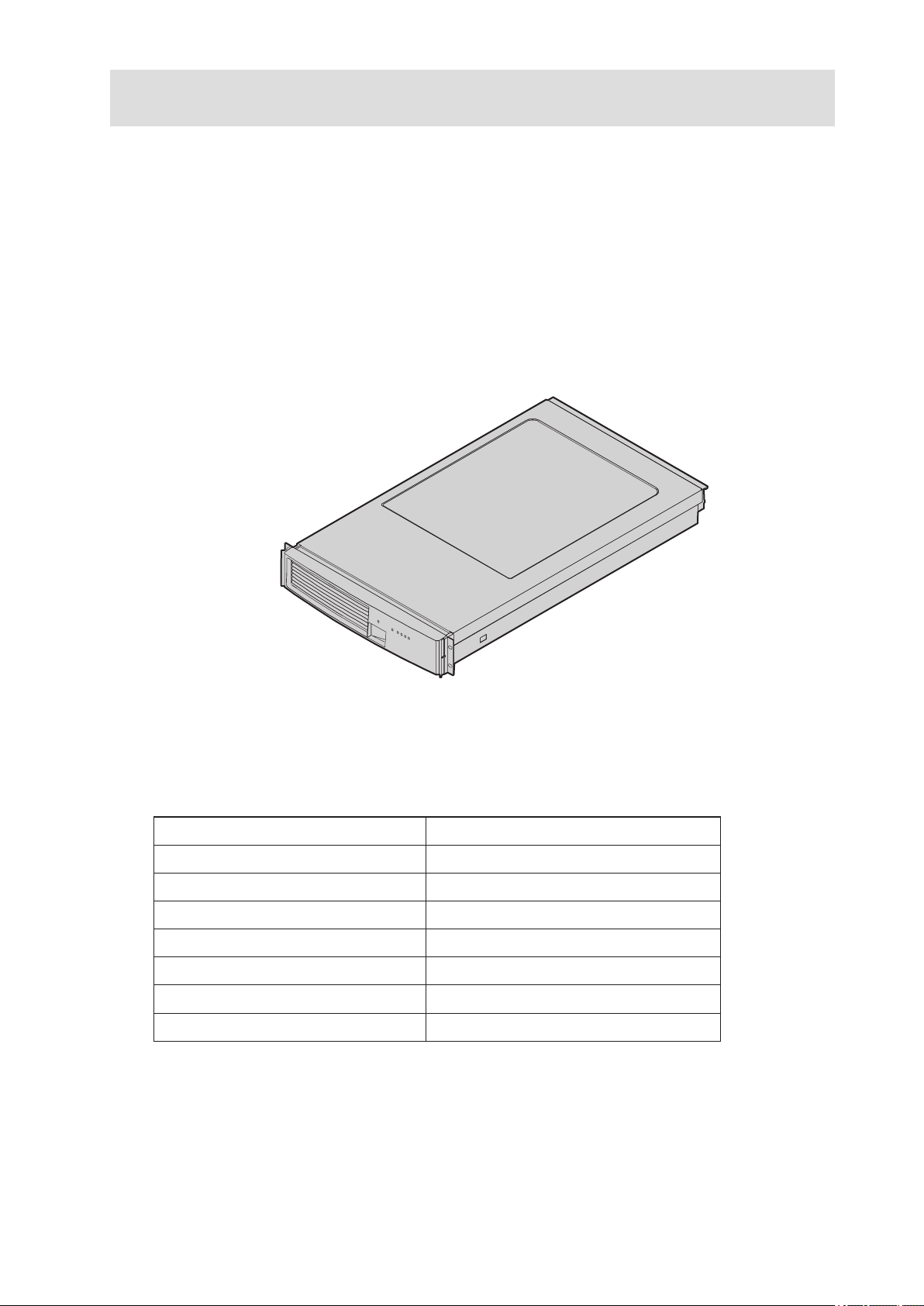
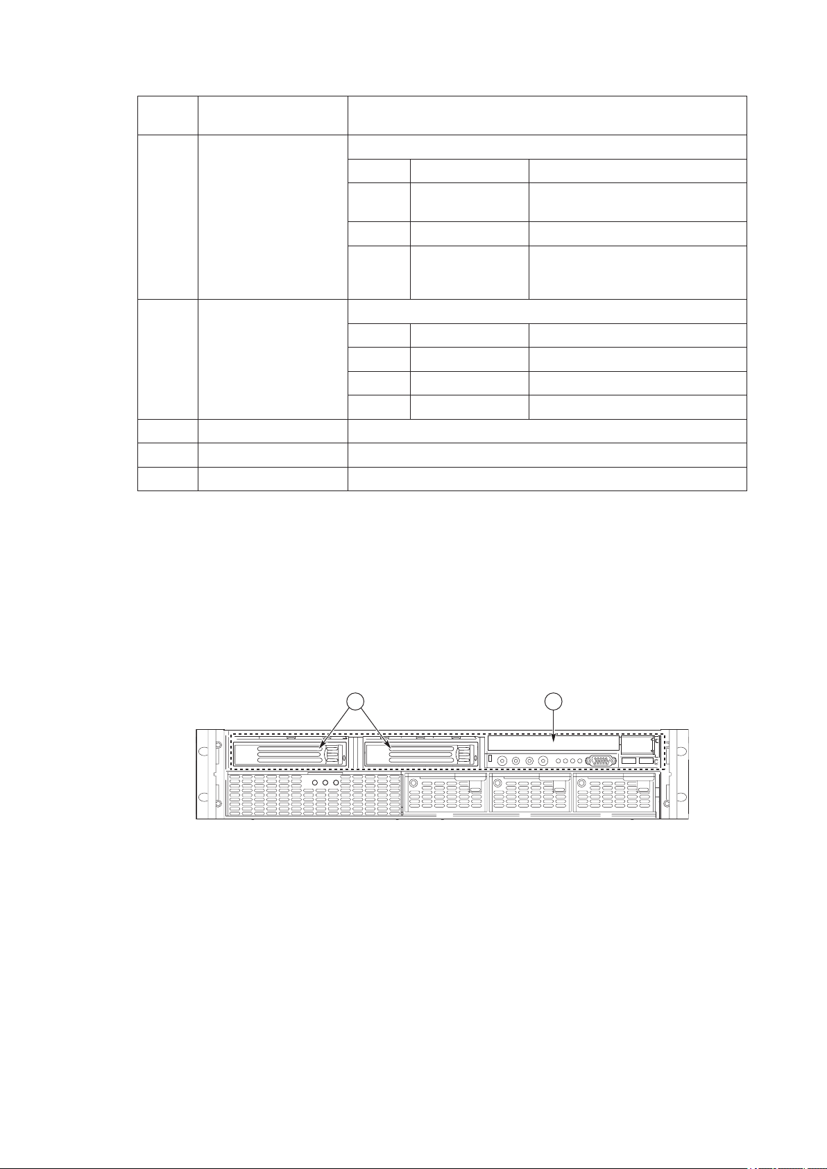
Figure 1 provides a diagram of the front and top of the server system, with the chassis cover in
place.
Figure 1. Server System Front
Table 1 provides the system dimensions and weight.
Table 1. Physical Specications
Specication Value
Height 3.4 inches (87 mm)
Width 17.7 inches (449 mm)
Depth 29.4 inches (747 mm)
Front clearance 3 inches (76 mm)
Side clearance 1 inch (25 mm)
Rear clearance 6 inches (152 mm)
Weight (note 1) 65 lbs (30 kg)
Note 1. The system weight listed above is an estimate for a fully configured system and will vary depending on the number
of peripheral devices and add-in cards as well as the number of processors and DIMMs installed in the system.

14 System Description
15MAXDATA PLATINUM 90002R Server System
Table 2 provides a list and brief description of the features of the server system.
Table 2. Feature Summary
Feature Description
Compact, high-density
system
Rack-mount server with a height of 2U (3 1/2 inches) and a depth of 28
inches
Configuration flexibility • 1-2 way capability in low profile and cost effective packaging
• Stand-alone system including external I/O slots/disk expansion as
needs grow
• Intel® Itanium® 2 processor support
• 16-GB Double Data Rate (DDR) Synchronous Dynamic Random
Access Memory (SDRAM) memory support
Serviceability • Front access to hot-swap hard drives
• Hot-swap fans
• Front access to hot-swap power supplies
• Dockable power to main board
• System power and reset status LEDs
• System ID switch on front panel and LEDs on front and back
• Color-coded parts to identify hot-swap and non-hot-swap serviceable
components
Availability • Three PCI-X slots
• Three hot-swap 350-W power supplies in a redundant (2+1)
configuration
• Dual redundant power cords (1+1) when three power supplies are
present
• Six hot-swap system fans in a redundant (5+1) configuration
• Two hot-swap 1-inch Ultra320 SCSI hard drives
Manageability • Remote management
• Emergency Management Port (EMP)
• Intelligent Platform Management Interface (IPMI) 1.5 compliant
• Wired For Management (WfM) 2.0 compliant
• Remote diagnostics support
Upgradeability and
investment protection
• Supports Intel® Itanium® 2 processors
• Field upgradeable to next generation (Montecito) processor family
• Multi-generational chassis
System-level scalability • Up to 16-GB DDR SDRAM (using 2-GB DIMMs)
• One to two Intel® Itanium® 2 processors
• External I/O (3 slots) / disk expansion
• External SCSI connector
Front panel • System Power switch and LED
• System Reset switch
• System Diagnostic Interrupt
(SDINT) switch
• System ID switch and LED
• System Status LED
• Hard Drive Fault LED
• LAN1 & LAN2 Status LEDs
• Video Connector
• Dual USB 1.1 Ports
Removable media • DVD/CDRW
• External USB floppy or key fob
15MAXDATA PLATINUM 90002R Server System
External Chassis Features
System controls and indicators are located in several places on the chassis as follows:
• Chassis front:
– Front panel: Front panel switches and LEDs
– Peripheral bay: Hard drive LEDs
– Power bay: Power Module LEDs and Power Supply LEDs
• Chassis back panel: System ID LEDs and LAN port LEDs
Each of these areas is discussed below.
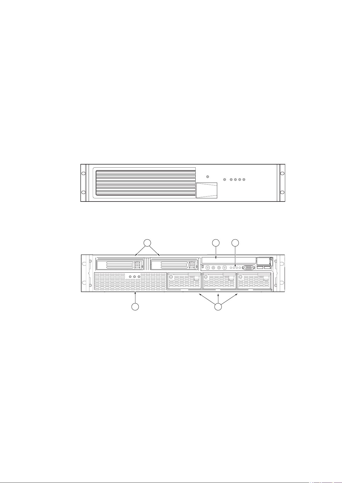
Chassis Front
The following gure shows the front of the chassis with the snap-on bezel in place. The bezel must be
removed to access the front panel switches, power supplies, SCSI drives and DVD-CDRW devices.
Figure 3 shows the front of the chassis with the bezel removed.
Figure 2. Server System Front with Bezel Installed
Figure 3. Server System Front with Bezel Removed
A. Hard drives D. Power supply modules
B. CD-ROM/DVD-ROM drive E. Power bay
C. Front panel
16 System Description
17MAXDATA PLATINUM 90002R Server System
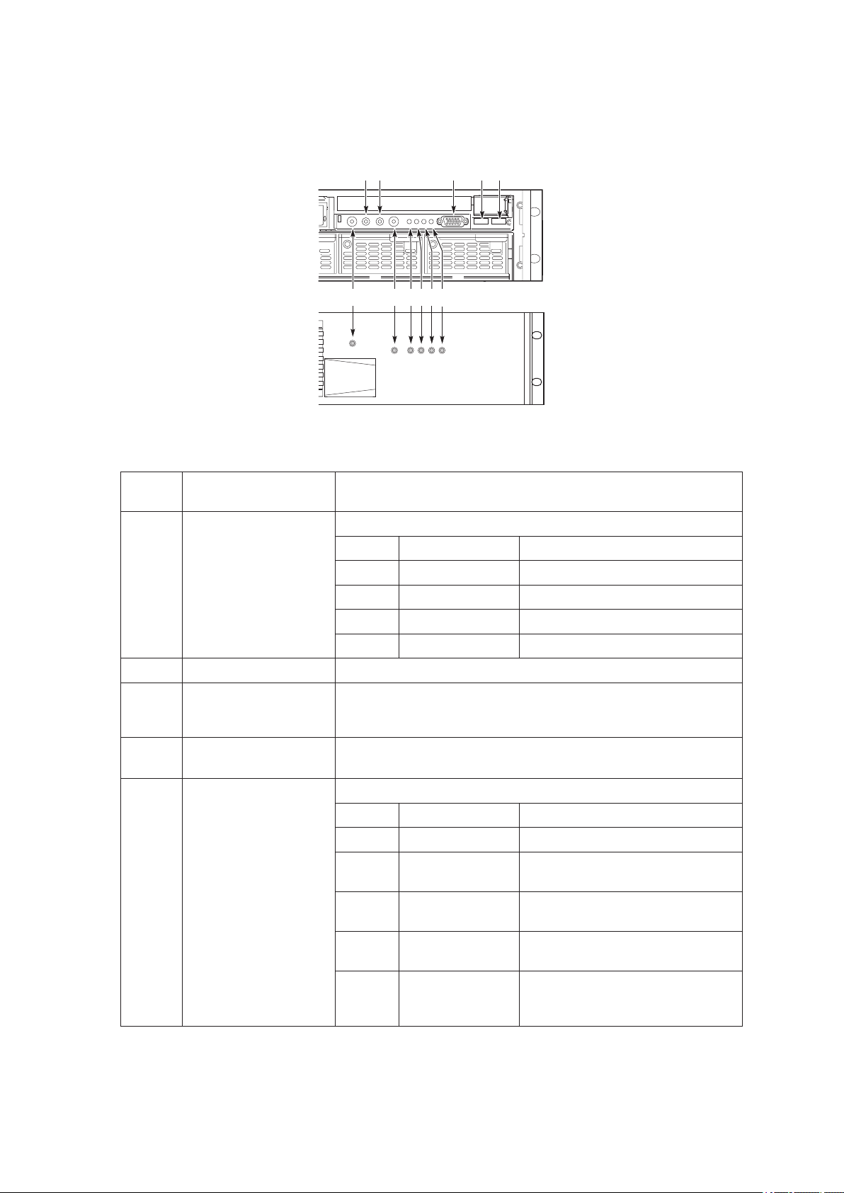
Front Panel
The front panel is located at the right side of the server system, at the front of the chassis. The front
control panel of the displays status lights for system status, hard drives, and power supplies.
Figure 4. Front Panel Controls, Indicators, and Connectors
Callout Control, Connector,
Indicator
Description
A. System Power switch
& LED
Toggles system power
LED State ACPI
Off Power off No
On Power on No
Off S5 Yes
On S0 Yes
B. System Reset switch Resets the system.
C. SDINT (System
Diagnostic Interrupt)
switch
Asserts SDINT
D. System ID switch and
LED (Blue)
System identification switch and light
E. System Status/Fault
LED (Green/Amber)
Indicates system status.
LED State Description
Off Not ready Post err/NMI Ev/CPU missing
Green,
solid
Ready No Alarms
Green,
blinking
Ready –
Degraded
CPU Fault, DIMM killed
Amber,
solid
Critical Alarm Critical of Pwr Flt, Fan, Voltage,
and Temperature failures.
Amber,
blinking
Non-Critical
Alarm
Non-Critical of redundant Pwr
Flt, redundant Fan, Voltage, and
Temperature failures.
continued
17MAXDATA PLATINUM 90002R Server System
(continued)
Callout Control, Connector,
Indicator
Description
F. Hard Drive Fault LED
(Amber)
Indicates hard drive subsystem fault status.
LED State Description
Off Drive Missing Slot Empty, Online, Prepare for
removal.
On Inactive Drive Failed
Blinking Inactive Drive Identity, Rebuild, Predictive
Fail, Rebuild Interrupt or Rebuild
on empty slot.
G, H. LAN1, LAN2 Status
LEDs (Green)
Indicates LAN activity status.
LED State Description
Off Idle
On Inactive No Access
Blinking Active Access
I. Video connector Video port, standard VGA compatible, 15-pin connector
J. USB3 connector USB port 3, 4-pin connector
H. USB4 connector USB port 2, 4-pin connector
Peripheral Bay
The peripheral bay supports up to two 1-inch hot-swap Ultra320 SCSI hard drives and one -inch
ATA-33 IDE DVD/CD-ROM drive.
The peripheral bay supports Low Voltage Differential (LVD) SCSI disk drives only. Single-Ended (SE)
SCSI devices are not supported in the peripheral bay, however SE device support is available via the
secondary external SCSI channel located at the rear of the chassis.
Figure 5. Peripheral Bay
A. Hard drives
B. CD-ROM/DVD-ROM drive
18 System Description
19MAXDATA PLATINUM 90002R Server System
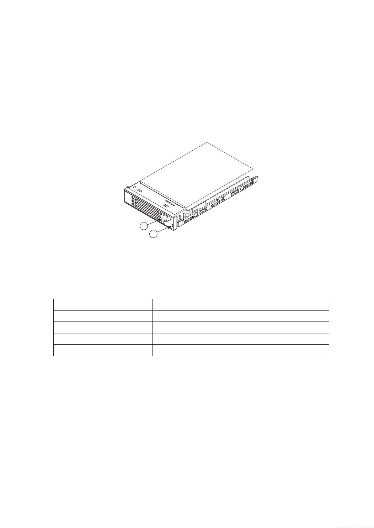
Hot-swap Hard Drive Carrier
The hot-swap hard drive carrier accepts 15,000-RPM and slower Ultra320 SCSI technology SCA-type
hard drives. The peripheral bay supports Low Voltage Differential (LVD) SCSI disk drives only. SingleEnded (SE) SCSI devices are not supported in the peripheral bay. SE drives are only supported on the
external SCSI connector. Hard drive carriers that accommodate 3.5-inch by 1.0-inch SCSI disk drives
are required as part of the hot-swap implementation. The disk drive is attached to the carrier with four
fasteners, and is retained in the chassis by a locking handle. Figure 6 shows a hard drive carrier that
has been removed from the peripheral bay. The drive is accessed by pressing the latch to release the
drive carrier door, then pulling out on the door.
The SCSI backplane board contains a dual-color LED for each hard drive. The LED can be seen at the
right edge of the carrier, as shown in the gure. The LED displays the drive status, as described in
Table 3.
A
B
Figure 6. Hard Drive Carrier
A. LED
B. Latch
Table 3. SCSI Hard Drive LED Details
Feature Description
Green, flashing Indicates the hard drive is active
Yellow/Green flashing Indicates a hard drive fault and hard drive is powered
Yellow/Blank flashing Indicates a hard drive fault and hard drive is not powered
Not illuminated Indicates no hard drive is installed in the bay
19MAXDATA PLATINUM 90002R Server System
Removable Media Drive Bay
!
CAUTION
The DVD/CD-ROM drive cannot be hot-swapped. In order to add, remove or replace a DVD/CD-ROM
drive, the system must be powered down, power sources unplugged and the top cover of the chassis
must be removed to access the DVD/CD-ROM drive area.
The slim-line DVD/CD-ROM drive is installed in a drive carrier that is inserted from the rear of the
peripheral bay. This device is not hot-swappable; you must switch off system power, remove all
power cords, open the chassis and then remove the peripheral bay to remove or install a CD-ROM
or DVD-ROM drive.
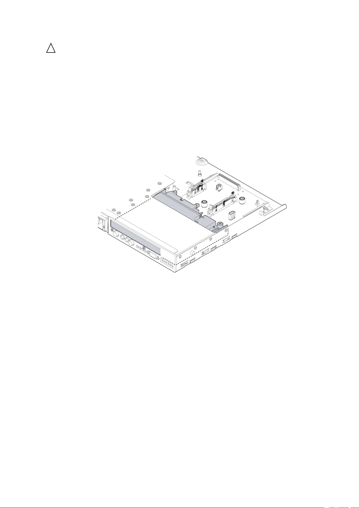
The CD-ROM/DVD-ROM drive snaps into the carrier as shown below and is secured by four raised
points. The raised points line up with the mounting holes on the sides of the drive. Two of these
mounting points are spring loaded and two are stationary.
Figure 7. DVD-ROM / CD-ROM Drive

20 System Description
21MAXDATA PLATINUM 90002R Server System
Power Supply Bay
The power supply bay, shown below, is located in the lower front of the system. Redundant power
status LED indicators are in the left portion of the power bay and three hot-swap power supply modules
dock into the three bays on the right.
Figure 8. Power Supply Bay
A. Power status LEDs
B. Power supply modules
The power subsystem can be congured as follows:
• Three power supply modules installed, (2+1) redundancy
• Two power supply modules installed, non-redundant
NOTE
The power supply modules must be populated from right to left. The left power supply module is
optional in a non-redundant conguration. If no module is installed in the left slot, a ller panel is
required for proper system cooling.
Two power supply modules are capable of handling the worst-case power requirements for a fully
congured server system. This includes two Intel® Itanium® 2 processors, 16 GB of memory, three
PCI add-in cards, two hard drives, and a DVD-ROM / CD-ROM drive.
When the system is congured with three power supply modules, the hot-swap feature allows you
to replace a failed power supply module while the system is running.
The power subsystem receives AC power through two power cords. When three power supply modules
and two power cords are installed, the system supports (1+1) power cord redundancy. This feature
allows the system to be powered by two separate AC sources. In this conguration, the system will
continue to function without interruption if one of the AC sources fails.
The AC power status LEDs in the power supply module provide information on the status of the
power sources. The LEDs are shown below, indicated by the letter “A” in the diagram. The possible
LED states are described below the diagram.
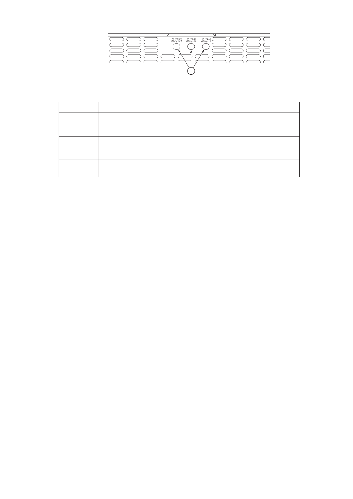
21MAXDATA PLATINUM 90002R Server System
A
Figure 9. AC Power Status LEDs
LED Description
AC1 (green) On - AC input #1 available.
Off - AC input #1 unavailable or below voltage threshold to power up the
system.
AC2 (green) On - AC input #2 available.
Off - AC input #2 unavailable or below voltage threshold to power up the
system.
ACR (green) On - redundant feature is available.
Off - redundant feature is not available
The power redundancy feature requires each of the following conditions be present.
• AC input #1 available
• AC input #2 available
• Power good signals asserted from all three power supply modules
• TS-OK signal is asserted
22 System Description
23MAXDATA PLATINUM 90002R Server System
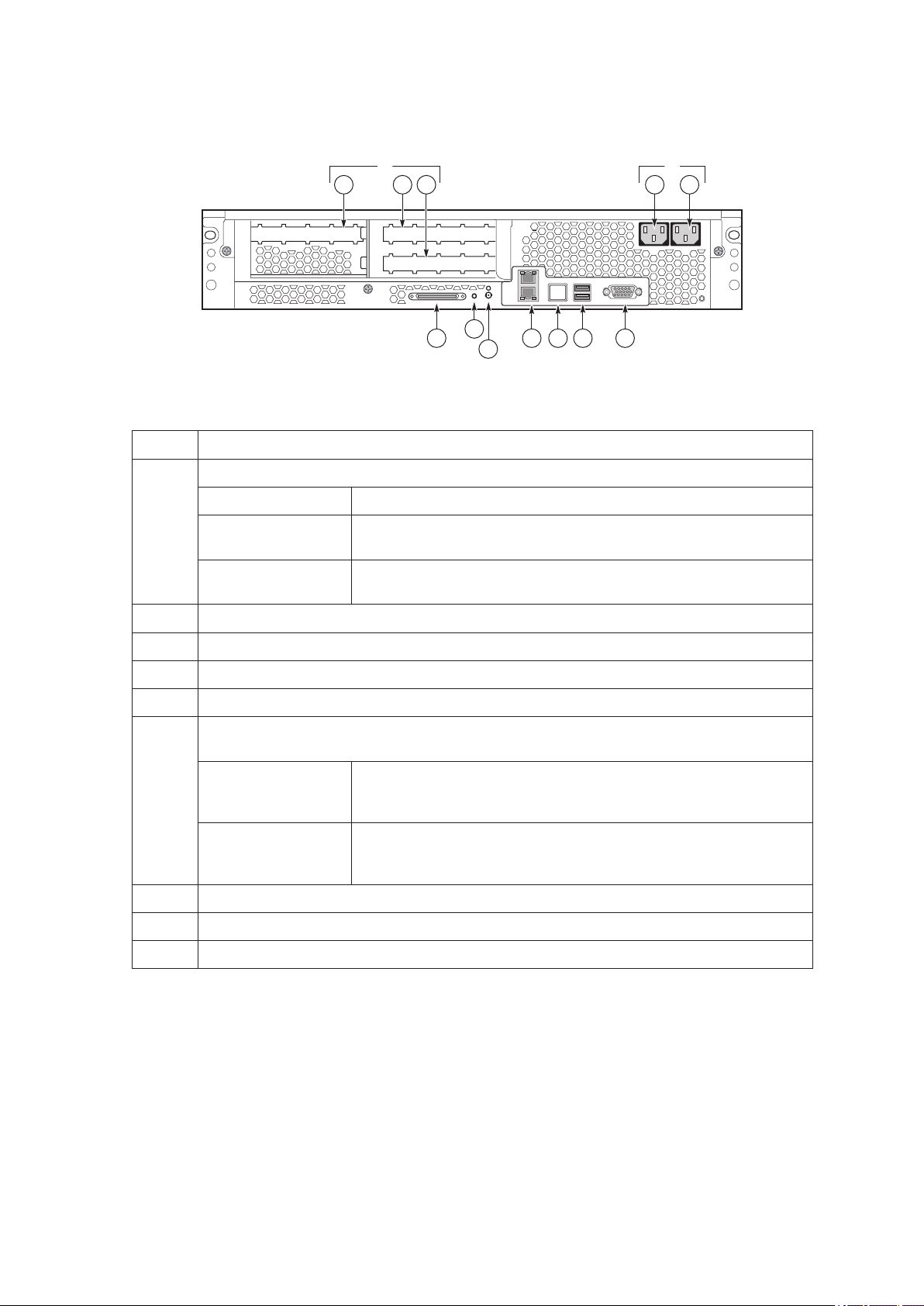
Chassis Rear
The gure below shows the rear of the system.
1 2
Figure 10. Chassis Rear Features
Callout Description
A.
Slot 2
Slot 3
PCI Slots
Slot 1 100 MHz, 64-bit PCI-X slot, full length
100 MHz, 64-bit PCIX slot, full length
133 MHz, 64-bit PCIX slot, full length
B. AC input power connectors (two)
C. External SCSI connector
1
D. System ID switch
E. System ID LED (blue)
F. Two LAN ports, RJ45 connector (LAN1 on bottom, LAN2 on top)
LAN port LEDs:
Status LED (Green) On – ethernet link is detected
Off – no ethernet connection
Blinking – ethernet link is active
Speed LED
(Green/Amber)
Off – 10 Mbps
Green On – 100 Mbps
Amber On – 1000 Mbps
G. Serial port2, RJ45 connector
H. Two USB 1.1 ports, 4-pin connectors (USB0 on bottom, USB1 on top)
I. Video port, standard VGA compatible, 15-pin connector
Notes:
1. External SCSI bus supports both LVDS and SE signals via the external SCSI connector.
2. EMP access is provided via shared serial port.
23MAXDATA PLATINUM 90002R Server System
Internal Chassis Features
!
WARNING
Only qualied technical personnel should access any internal system component. Some exposed
circuits exceed 240 VA and may cause injury if accidentally contacted.
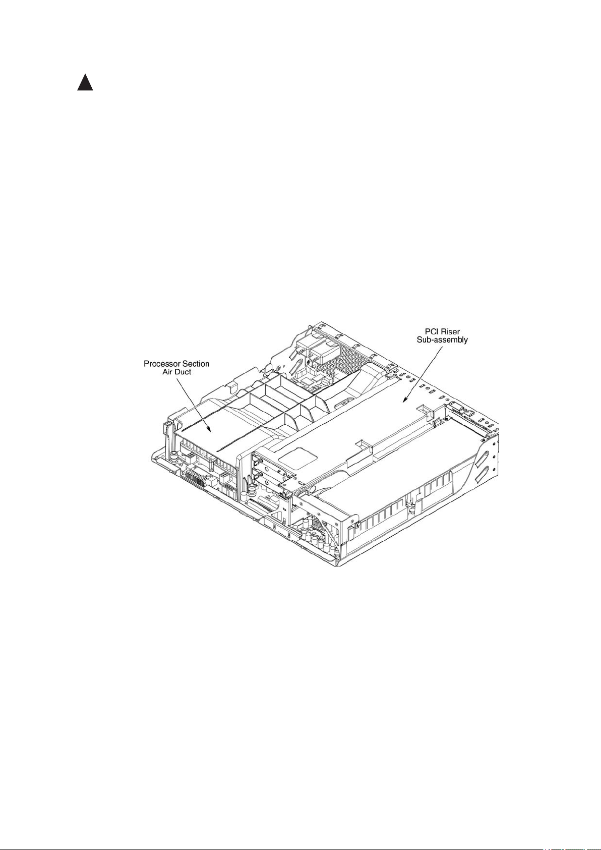
Electronics Bay
The electronics bay, shown in the two gures below, consists of the following:
• Main board
• PCI riser board
• Two processor locations and two power pod locations
• Eight DIMM slots
• Air duct for the processor area
• PCI riser bracket to support PCI riser board and PCI cards
• Connectors, switches and LEDs at the rear of the chassis (see Figure 10)
Figure 11. Electronics Bay
A. Processor air duct with processor(s) installed underneath
B. PCI riser sub-assembly with PCI cards installed
24 System Description
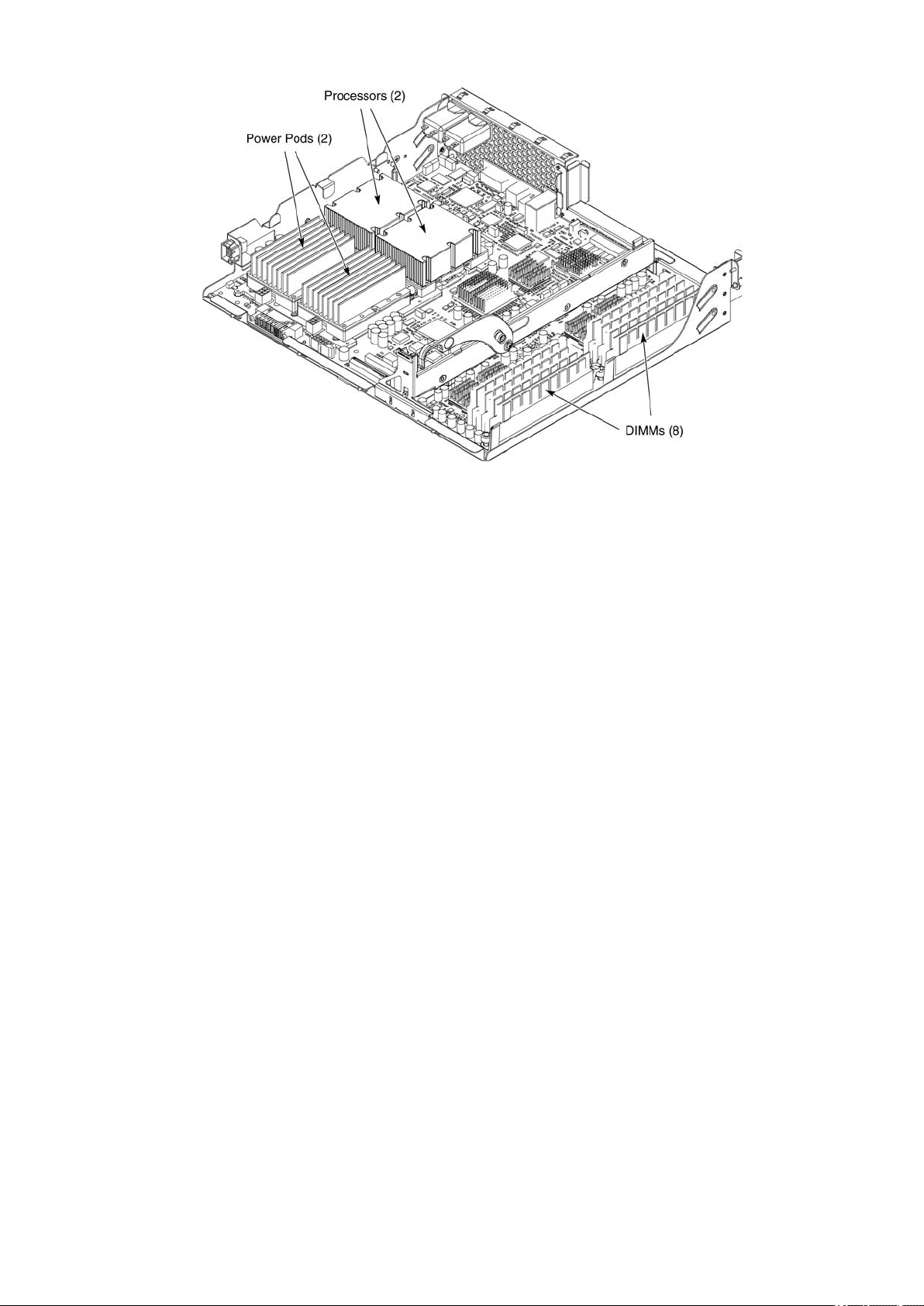
25MAXDATA PLATINUM 90002R Server System
Figure 12. Electronics Bay (sub-assembly removed)
A. Processor pods (2 shown installed)
B. Processors (2 shown installed)
C. DIMMs (8 shown installed)
25MAXDATA PLATINUM 90002R Server System
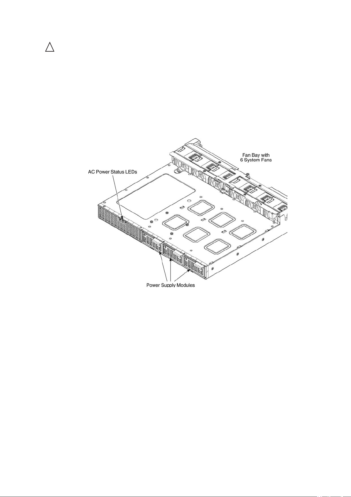
Cooling Subsystem
!
CAUTIONS
The chassis top cover must be installed and closed for proper system cooling.
Cooling components must be hot-swapped within a limited time period. This time period applies only
to the time that the cooling component is removed from the system, not from the time of failure.
The cooling subsystem consists of a hot-swap, redundant (5+1) system fan array installed in the
fan bay. The single bank of six Delta FFB0612EHE-S18Z hot-swap system fans provide the airow
necessary to cool the system components. These fans are installed in the fan bay that is located
within the power bay. The fans connect to the fan baseboard. The gure below shows the location
of the fans in the power bay.
Figure 13. Power Bay (removed from chassis)
A. AC power status LEDs (three)
B. Fan bay (six installed fans)
C. Power supply modules (three)
26 System Description
27MAXDATA PLATINUM 90002R Server System
The gure below shows the cooling subsystem layout with the airow direction indicated.
Figure 14. Cooling Subsystem Layout
The server system supports only a fully populated system fan conguration. However, the system
will continue to meet thermal specications with either a system fan or a power supply failure. The
power supply redundancy feature applies to systems with three power modules installed.
If a fan fails, system cooling is maintained and the system continues to operate while the failed fan
is being hot-swapped. All system fans have tachometer output, internal speed control, and external
Pulse Width Modulation (PWM) speed control.
A failure is detected when the RPM of a fan falls below a predetermined minimum threshold (Approx.
5000 RPM). If a system fan falls below this threshold, all fans will be boosted to operate at a higher
speed (Approx. 8500 RPM)
The fans will also be boosted to the higher speed if a power supply fails for any reason (including loss
of AC power). The fans will not be boosted if the Redundant (ACR) power supply fails. If the redundant
power supply fails, the system fans will not be affected.
When boosted, all fans remain at high speed until the failed fan or power supply is replaced. When
a fan replacement is detected by a change in state of the fan presence signal. After a failed fan is
replaced, the fans return to the lower speed and fan failure monitoring at the lower speed levels is
reactivated.
When a power supply fails and is replaced, the replacement is detected by server management.

27MAXDATA PLATINUM 90002R Server System
NOTES
Do not attempt to operate this system with less than a fully populated, six system fan
conguration.
To maintain adequate cooling for system components, the swap process must be completed in
two-minutes. This period only applies to the time that the fan or power supply is removed from the
system, not from the time of failure.
A system fan failure is indicated by the corresponding fan LED and by the Cooling Fault LED on the
front panel. The system fan LEDs are shown in the gure below. The LED is amber and turns on if
a system fan failure occurs. These LEDs can be seen only when the top cover is removed from the
chassis.
Figure 15. System Fan Status LED
A. Fan LEDs (two of six pointed out)
Power Subsystem
Power Supply Modules
The power supply modules are Server System Infrastructure (SSI) compliant, universal AC input with
Power Factor Correction (PFC) Thin Power Supplies (TPS). The power supply modules are auto-sens
over the input range of 200-240 VAC and 100-127 VAC. They are rated at 350 W each. The combined
continuous output power for all outputs has been designed such that they will not exceed 650W.
The DC output specication for the power supply is met by two power supply modules operating
in the power bay. A third power module can be inserted to enable redundancy. When operated in
parallel, the power modules share the total load currents equally within the limits specied, and meet
all performance requirements. Two power supply modules are capable of handling the worst-case
power requirements for a fully congured system: Two processors, 16 GB of memory, three PCI-X
add-in cards, two hard drives and a DVD or CD drive.
In the unlikely event that a power module fails in a redundantly paralleled group, or upon the removal
of an operational or failed supply from a redundantly paralleled group, the action will not cause DC
output transients in excess of specied limits. Conversely, adding an operational or failed supply to a
paralleled group will not cause DC output transients in excess of the limits specied.

28 System Description 29MAXDATA PLATINUM 90002R Server System
Redundant AC Power Source Operation
The power bay has two AC inlets, labeled AC1 and AC2, located at the rear of the chassis. AC1 is
connected to the inputs of power supply module PS1. AC2 is connected to module PS2 and the
redundant power module PS-Shared, through normally closed transfer switch contacts.
• If AC1 input fails or exceeds the specied voltage range, AC2 will transfer power to the two
modules located in the positions labled PS2 and PS-Shared.
• If AC2 input fails, the AC transfer switch automatically switches from AC2 to AC1. As result,
AC1 connects to the two power supply modules located in locations PS1 and PS-Shared. After
AC2 recovers, the AC transfer switch resets to its original state. This feature allows the system
to be powered by two separate AC sources. In this conguration, the system continues to
operate without interruption if one of the AC sources fails.
Processor Power Pods
Dedicated power pods supply power to each processor. The input connector of the power pod is
connected to the 12 VDC power on the main board via a short ‘Y’ cable. The output connector of the
power pod mates directly with the edge of the processor package.

2 Board Set Description
This chapter highlights the main features of the board set. The board set contains the following:
• Main board
• PCI riser board
In addition, the server contains the following system boards:
• SCSI board
• Front panel board
Major components of the board set include:
• Intel® Itanium® 2 processors
• Intel® E8870 chip set
• High-capacity DDR SDRAM memory
• High-bandwidth I/O subsystem supporting PCI and PCI-X
The gure on the following page displays a block diagram of the system and the board set within
the system.
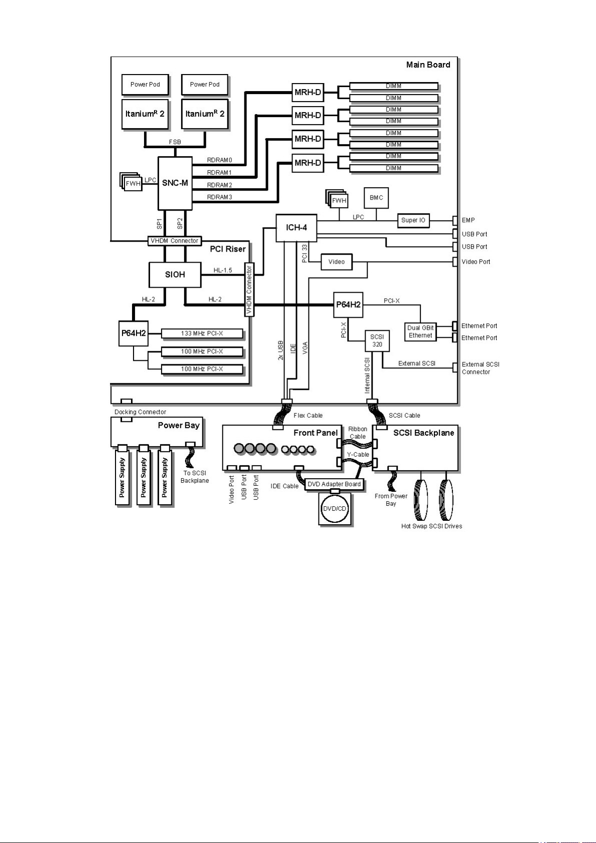
30 Board Set Description
31MAXDATA PLATINUM 90002R Server System
Figure 16. System Architecture Layout
 Loading...