

Page 1

User‘s Manual
MAXDATA PLATINUM 9000-2R Server
Page 2

2
Contents
3
MAXDATA PLATINUM 9000-2R Server
Page 3

3
MAXDATA PLATINUM 9000-2R Server
Contents
Safety Precautions 5
Safety Steps ...........................................................................................................................................5
1 Specifications and Disclaimers 7
Declaration of the Manufacturer ............................................................................................................8
Safety Compliance .................................................................................................................................8
Electromagnetic Compatibility (EMC).....................................................................................................8
Laser Compliance Notice .......................................................................................................................8
Electromagnetic Compatibility Notices (International)............................................................................8
Europe (CE Declaration of Conformity) .............................................................................................8
2 Setting up the system 9
Removing the Server from the Box........................................................................................................9
Selecting a Site.......................................................................................................................................9
Checking Power Cords.........................................................................................................................10
Connections and Controls .................................................................................................................... 11
Connecting the Monitor, Keyboard, and Mouse ..................................................................................15
Powering On the Server for the First Time .......................................................................................... 15
Mounting the DVD/CD-RW Device ......................................................................................................16
The MAXDATA PLATINUM 9000-2R Server Resource CD..................................................................17
The MAXDATA PLATINUM 9000-2R Server Product Guide ................................................................ 17
Figures
1. MAXDATA PLATINUM 9000-2R Server ............................................................................................7
2. Chassis Front View..........................................................................................................................11
3. Front View of MAXDATA PLATINUM 9000-2R Server (Shown with Bezel Removed) ..................11
4. Front Panel View ............................................................................................................................. 12
5. Chassis Back Features ................................................................................................................... 14
Tables
1. MAXDATA PLATINUM 9000-2R Server Physical Specifications.......................................................7
2. Front Panel Control and Indicator Description.................................................................................12
3. Back Panel Features........................................................................................................................14
Page 4

4
Contents
Page 5
5
MAXDATA PLATINUM 9000-2R Server
Safety Precautions
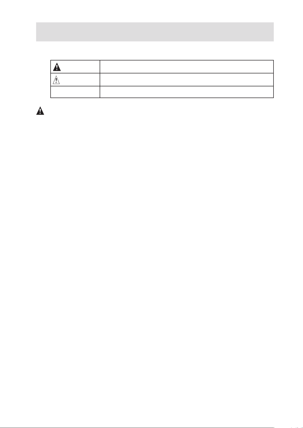
The Following safety symbols are used in this manual:
WARNING
Failure to follow these guidelines may result in personal injury or even death
CAUTION
Failure to follow these guidelines may result in damage to the system or its
components
NOTE
General usage tips
WARNINGS
The power supply in this product contains no user-serviceable parts. There may be more than one
supply in this product. Refer servicing only to qualified personnel.
Do not attempt to modify or use the supplied AC power cord if it is not the exact type required. A
product might be equipped with more than one AC power cord.
The power button on the system does not turn off all system AC power. To remove all AC power
from the system, you must unplug each AC power cord from the wall outlet or power supply.
To avoid injury from electrical and mechanical hazards, chassis covers should only be removed by
qualified service personnel.
Safety Steps
Whenever you remove the chassis covers to access the inside of the system, follow these steps:
1. Turn off all peripheral devices connected to the system.
2. Turn off the system by pressing the power button.
3. Unplug all AC power cords from the system or from wall outlets.
4. Label and disconnect all telecommunication cables and all other cables connected to
I/O connectors or ports on the back of the system.
5. Provide some electrostatic discharge (ESD) protection by wearing an anti-static wrist
strap attached to chassis ground of the system – any unpainted metal surface – when
handling components.
6. Do not operate the system with the chassis covers removed.
After you have completed the six safety steps above, remove the covers as follows:
1. To open the top back cover, push the sliding latches on the top of the cover and pull the
cover toward the back of the chassis.
2. To remove the top back cover, continue to slide the cover toward the back of the chassis
until it reaches the end-stops. Press the latch on the left rail slide and pull the cover until it
clears the chassis.
3. To remove the top front cover, loosen the two captive screws on either side of the cover,
slide the cover toward the front of the chassis until it stops, then lift the cover off.
4. Always replace the covers before operating the system.
Page 6
6
Safety Precautions
CAUTION
For proper cooling and airflow, unless hot swapping PCI cards or fans, always reinstall the chassis
covers before turning on the system. Operating the system without the covers in place can damage
system parts. To install the covers:
1. Check first to make sure you have not left loose tools or parts inside the system.
2. Check that cables, add-in boards, and other components are properly installed.
3. To replace the top back cover, slide the two bearing cages on the back top cover all
the way to the end of the slides.
4. Place the top cover on the cover slides and push the cover into place.
5. To replace the top front cover, attach the back edge of the front top cover to the chassis,
lower the front edge of the cover onto the chassis, then push the cover into place.
6. Tighten the two captive screws on either side of the cover.
7. Connect all external cables and the AC power cord(s) to the system.
WARNING
A microprocessor and heat sink might be hot if the system has been running. Also, there might be
sharp pins and edges on some board and chassis parts. Contact should be made with care. Consider
wearing protective gloves.
WARNING
Danger of explosion if the battery is incorrectly replaced. Replace only with the same or equivalent type
recommended by the equipment manufacturer. Discard used batteries according to manufacturer’s
instructions.
The system is designed to operate in a typical office environment. Choose a site that is:
• Clean and free of airborne particles (other than normal room dust).
• Well-ventilated and away from sources of heat including direct sunlight.
• Away from sources of vibration or physical shock.
• Isolated from strong electromagnetic fields produced by electrical devices.
• Protected when in regions that are susceptible to electrical storms. We recommend you
plug your system into a surge suppresser and disconnect telecommunication lines to your
modem during an electrical storm.
• Provided with a properly grounded wall outlet.
• Provided with sufficient space to access the power supply cords, because they serve as
the product’s main power disconnect.
WARNING
Servers can be too heavy for a single person to lift or move safely. Depending on the server, use two
people or a mechanical assist to lift or move the server.
Page 7
7
MAXDATA PLATINUM 9000-2R Server
1 Specifications and Disclaimers
Server Specifications
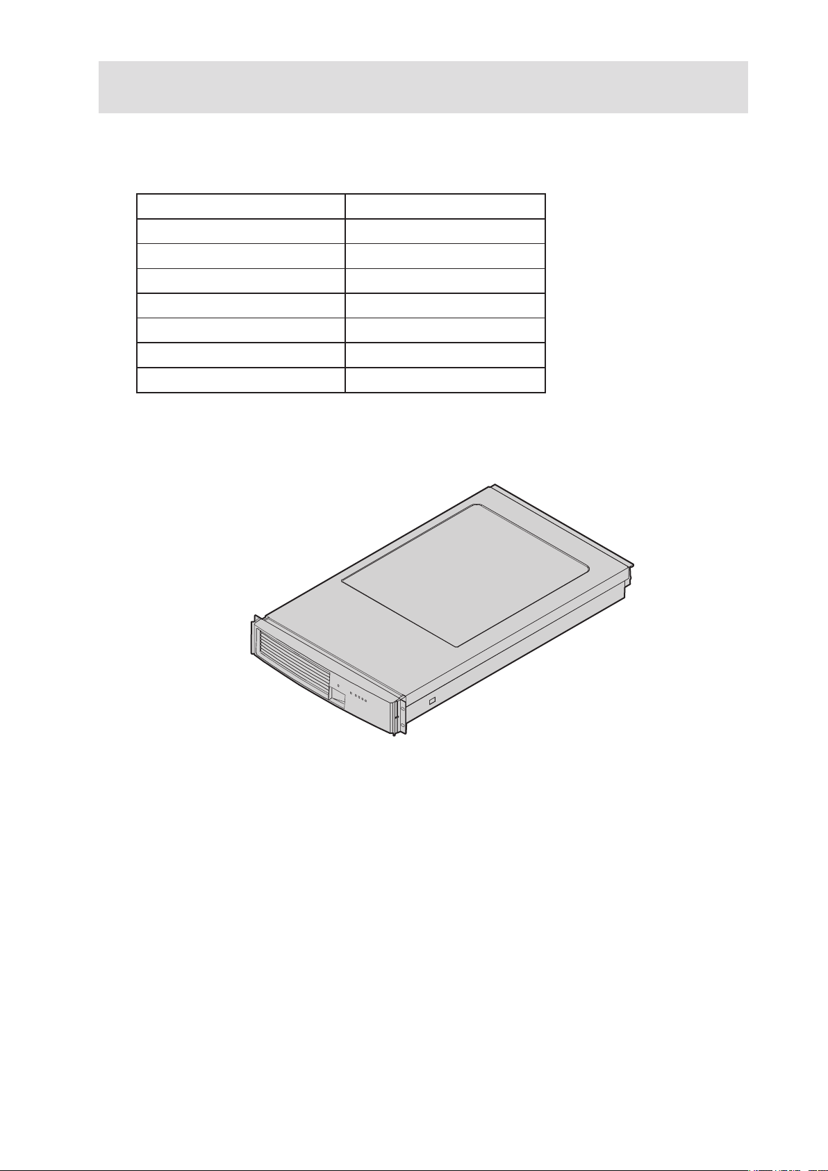
Table 1. MAXDATA PLATINUM 9000-2R Server Physical Specifications
Specification Value
Height 3.4 inches (87 mm)
Width 17.7 inches (449 mm)
Depth 29.4 inches (747 mm)
Front clearance 3 inches (76 mm)
Side clearance 1 inch (25 mm)
Rear clearance 6 inches (152 mm)
Weight 65 lbs (30 kg)
The system weight listed above is an estimate for a fully configured system and will vary depending
on number of peripheral devices and add-in cards as well as the number of processors and DIMMs
installed in the system.
Figure 1. MAXDATA PLATINUM 9000-2R Server
Page 8

8
Specifications and Disclaimers
Declaration of the Manufacturer
We hereby certify that this product is in compliance with European Union EMC Directive 89/336/EEC,
using standards EN55022 (Class A) and EN55024 and Low Voltage Directive 73/23/EEC, Standard
EN60950.
Safety Compliance
Europe
Low Voltage Directive, 73/23/EECTUV/GS to EN60950 2nd Edition with
Amendments, A1 = A2 + A3 + A4
Electromagnetic Compatibility (EMC)
Europe
EMC Directive, 89/336/EEC
• EN55022, Class A Limit, Radiated & Conducted Emissions
• EN55024, ITE Specific Immunity Standard
• EN61000-4-2, ESD Immunity
(Level 2 Contact Discharge, Level 3 Air Discharge)
• EN61000-4-3, Radiated Immunity (Level 2)
• EN61000-4-4, Electrical Fast Transient (Level 2)
• EN61000-4-5, AC Surge
• EN61000-4-6, Conducted RF
• EN61000-4-8, Power Frequency Magnetic Fields
• EN61000-4-11, Voltage Dips and Interrupts
• EN61000-3-2, Limit for Harmonic Current Emissions
• EN61000-3-3, Voltage Flicker
Laser Compliance Notice
MAXDATA products that use laser technology comply with Class 1 laser requirements.
Class 1 Laser Product
Luokan 1 Laserlaite
Klasse 1 Laser Apparat
Laser Klasse 1
NOTE
Class A device definition: If a Class A device is installed within this system, then the system is to be
considered a Class A system. In this configuration, operation of this equipment in a residential area
is likely to cause harmful interference.
Electromagnetic Compatibility Notices (International)
Europe (CE Declaration of Conformity)
This product has been tested in accordance too, and complies with the Low Voltage Directive (73/23/
EEC) and EMC Directive (89/336/EEC). The product has been marked with the CE Mark to illustrate
its compliance.
Page 9
9
MAXDATA PLATINUM 9000-2R Server
2 Setting up the system
Removing the Server from the Box
Carefully unpack the server. Be sure to use two people to lift the server. Do not attempt to lift or move
the server by the handles on the power supplies. If you need to move the server from one location
to another, use a hand-truck or other mechanical assist unit.
WARNING
Avoid injury: To avoid personal injury when unpacking the server, use only a mechanical assist unit
to lift it off the shipping pallet. The maximum server configuration weighs 30 kg.
Selecting a Site
The server operates reliably within normal office environmental limits. Select a site that meets these
criteria:
• Near a properly earthed, grounded three-pronged power outlet
– In the United States and Canada: A NEMA-compliant, 110-208V~ outlet rated for
15 amps
– In other geographic areas: A properly grounded, earthed outlet in accordance with
the local electrical authorities and electrical code of the region
• Clean and relatively free of excess dust
• Well ventilated and away from sources of heat, with the ventilating openings on the
server kept free of obstructions.
• Away from sources of vibration or physical shock
• Isolated from strong electromagnetic fields and noise caused by electrical devices such
as elevators, copy machines, air conditioners, large fans, large electric motors, radio and
TV transmitters, and high-frequency security devices
CAUTION, ESD Precautions
Electrostatic discharge (ESD) can damage disk drives, add-in boards, and other parts. This server can
withstand normal levels of environmental ESD. However, we recommend doing all procedures in
this guide only at an ESD-protected workstation. If one is not available, you can provide some ESD
protection by wearing an anti-static wrist strap attached to chassis ground of the server when handling
components (e.g., any unpainted metal surface).
CAUTION
Grounded outlet: Make sure that the power service connection is through a properly grounded outlet.
Temperature: The range of temperatures in which the server operates when installed in an equipment
rack, must not go below 5° C (41° F) or rise above 35° C (95° F). Extreme fluctuations in temperature
can cause a variety of problems in your server.
Ventilation: The equipment rack must provide sufficient airflow to the front of the server to maintain
proper cooling. The rack must also include ventilation sufficient to exhaust a maximum of 1500 W
(5,100 BTU/hr) for the server. The rack selected and the ventilation provided must be suitable to the
environment in which the server will be used.
Page 10

10
Setting up the system
11
MAXDATA PLATINUM 9000-2R Server
Checking Power Cords
WARNING
The Power button on the front control panel of the server does not completely remove AC power.
To completely remove AC power from the server, you must unplug both AC power cords from the
system or from the wall outlet. Unplugging the cords removes the +12 Volt standby power that is
present when the server is powered down.
WARNING
Do not attempt to modify or use an AC power cord that is not the exact type required. You must use
a power cord that meets the following criteria:
1. Rating: For U.S./Canada cords must be UL Listed/CSA Certified, 16/3, 75C type, VW-1,
SJT/SVT, with NEMA 5-15P or NEMA 6-15P attachment plug and IEC 320 C13 input power
connector rated 15 amps. For outside U.S./Canada cords must be flexible harmonized
(<HAR>) rated 250V, 1.0 mm minimum conductor size with IEC 320 C13 input power
connector and rated for no less than 10 amps.
2. AC Attachment Connector, wall outlet end for outside U.S./Canada: The AC wall
attachment plug should be a three conductor grounding type, rated at 125 V, 15 amps and
must be for the configuration of the specific region or country. The AC wall attachment
plug must bear at least an accepted safety agency certification mark for the specific
region or country.
3. Input Power Connector, server end: The connectors that plug into the AC receptacles
on the server must be an IEC 320, sheet C13, type female connector and are rated for
125V/250V, 15 A.
NOTES
Surge Suppressor Recommendations: In geographic regions that are susceptible to electrical storms,
we highly recommend that you plug the server into a surge suppressor.
EMI Information: For information about complying with electromagnetic interference regulations,
see “Electromagnetic Compatibility” in the MAXDATA PLATINUM 9000-2R Server System ProductGuide.
Page 11
11
MAXDATA PLATINUM 9000-2R Server
Connections and Controls
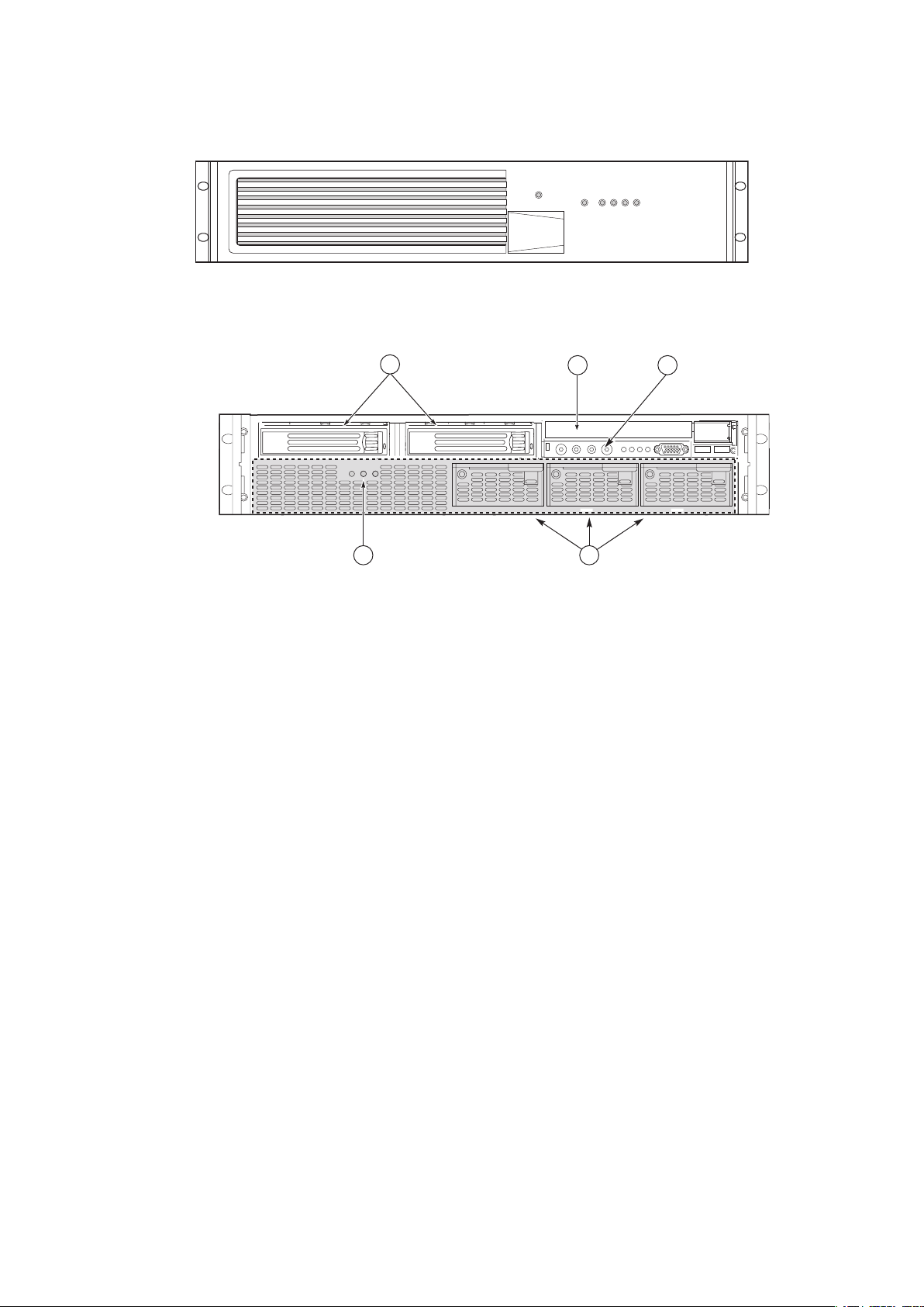
Figure 2 and Figure 3 show the chassis front view and the peripheral bay module.
Figure 2. Chassis Front View
Figure 3. Front View of MAXDATA PLATINUM 9000-2R Server
(Shown with Bezel Removed)
A.
Hard Drives
B.
CD-ROM/DVD Drive
C.
Front Panel
D.
Power Supply Modules
E.
Power Bay
Page 12
12
Setting up the system
13
MAXDATA PLATINUM 9000-2R Server
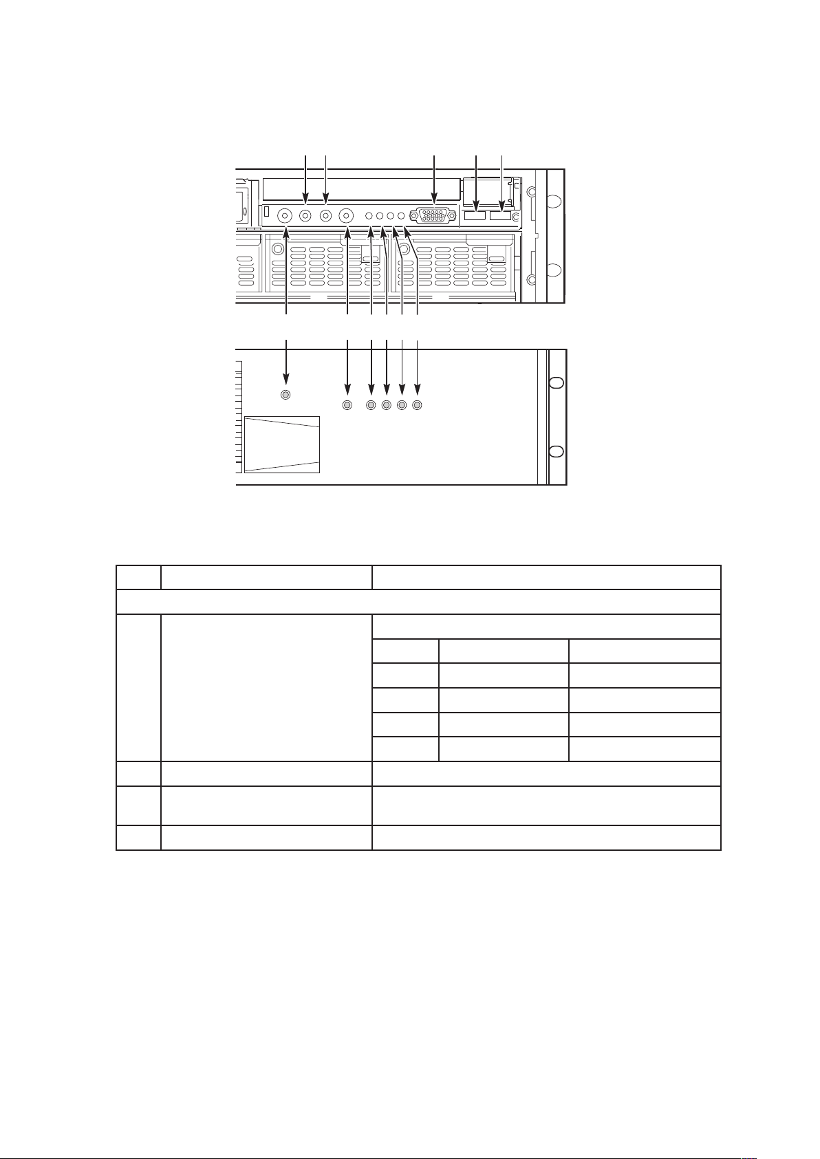
Figure 4 shows the front control panel of the Server System. The front control panel of the server
displays status lights for system status, hard drives, and power supplies.
Figure 4. Front Panel View
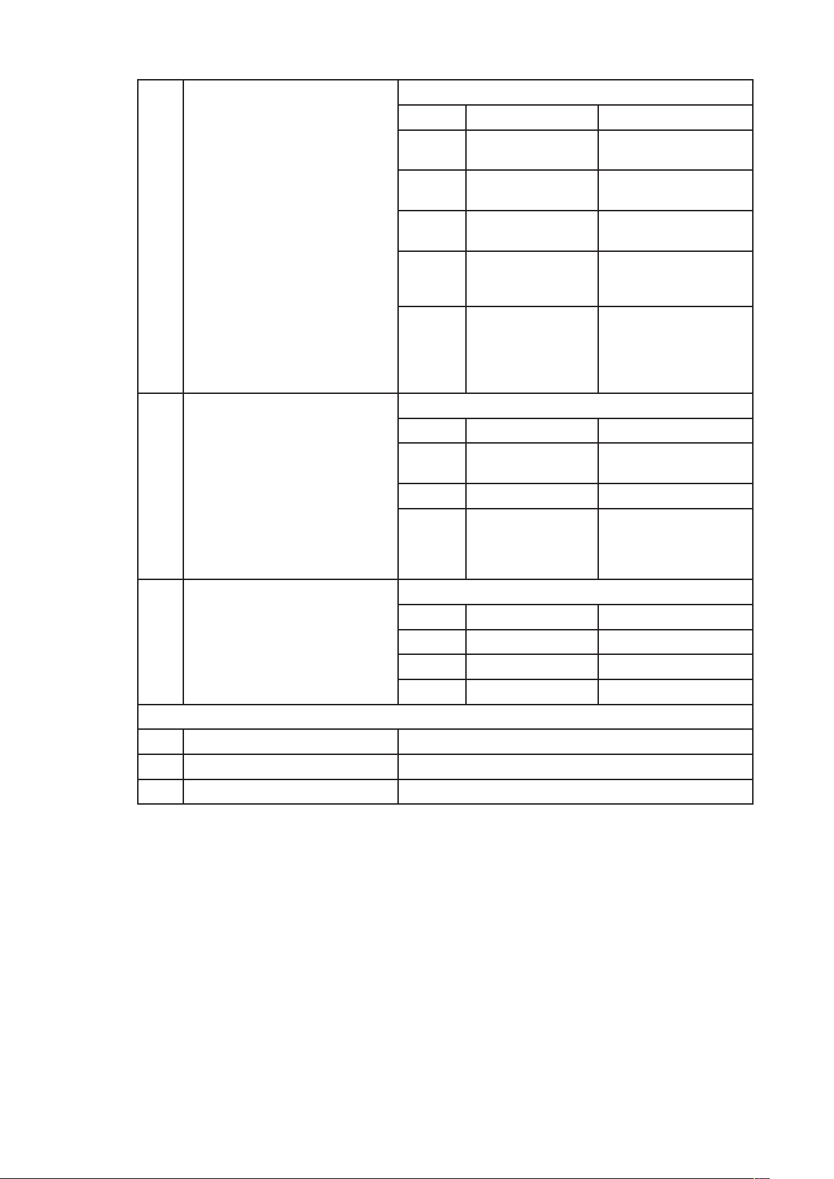
Table 2. Front Panel Control and Indicator Description
Item Feature Description
Front Panel Switches and LED Indicators
A.
System Power switch and LED Toggles system power
LED State ACPI
Off Power off No
On Power on No
Off S4 / S5 Yes
On S0 Yes
B.
System Reset switch Resets the system
C.
SDINT (System Diagnostic
Interrupt) switch
Asserts SDINT
D.
System ID switch and LED (Blue) System identification switch and light
Page 13
13
MAXDATA PLATINUM 9000-2R Server
E.
System Status/Fault LED
(Green/Amber)
Indicates system status
LED State Description
Off Not ready Post err/NMI Ev/CPU
missing
Green, OnReady No Alarms
Green,
Blinking
Ready – Degraded CPU Fault, DIMM killed
Amber, OnCritical Alarm Critical of Pwr Flt,
Fan, Voltage, and
Temperature failures.
Amber,
Blinking
Non-Critical Alarm Non-Critical of
redundant Pwr
Flt, redundant
Fan, Voltage, and
Temperature failures.
F.
Hard Drive Fault LED (Amber) Indicates Hard drive subsystem fault status
LED State Description
Off Drive Missing Slot Empty, Online,
Prepare for removal.
On Inactive Drive Failed
Blinking Drive Identity, Rebuild,
Predictive Fail, Rebuild
Interrupt or Rebuild on
empty slot.
G.,
H.
LAN1, LAN2 Status LEDs (Green) Indicates LAN activity status
LED State Description
Off Inactive No Connection or Link
On Idle Link and No Activity
Blinking Active Access / Activity
Front Panel Connectors
I.
Video connector Video port, standard VGA compatible, 15-pin connector
J.
USB3 connector USB port 3, 4-pin connector
K.
USB4 connector USB port 4, 4-pin connector
Page 14
14
Setting up the system
15
MAXDATA PLATINUM 9000-2R Server
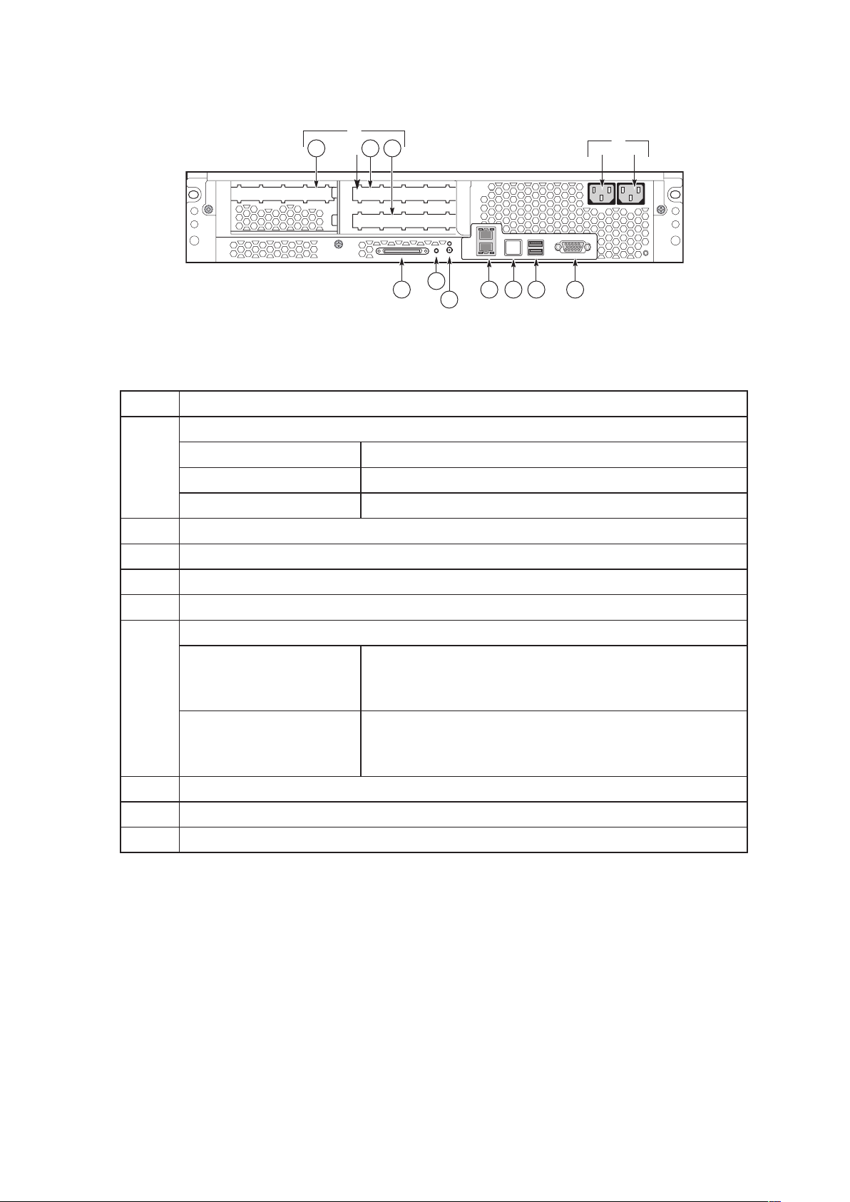
Figure 5 shows the features found on the chassis back panel.
Figure 5. Chassis Back Features
Table 3. Back Panel Features
Item Description
A.
PCI Slots
Slot 1 100 MHz, 64-bit PCI-X slot, full length
Slot 2 100 MHz, 64-bit PCI-X slot, full length
Slot 3 133 MHz, 64-bit PCI-X slot, full length
B.
Two AC input power connectors
C.
External SCSI connector1
D.
System ID switch
E.
System ID LED (blue)
F.
Two LAN ports, RJ45 connector (LAN1 on bottom, LAN2 on top) LAN port LEDs:
Green LED On – ethernet link is detected
Off – no ethernet connection
Blinking – ethernet link is active
Green/Amber dual color
LED
Ethernet speed indicator
Green On – 100 Mbps
Amber On – 1000 Mbps
G.
Serial port2, RJ45 connector
H.
Two USB 1.1 ports, 4-pin connectors (USB0 on bottom, USB1 on top)
I.
Video port, standard VGA compatible, 15-pin connector
NOTE
1. External SCSI bus supports both LVDS and SE signals via the external SCSI connector.
2. EMP access is provided via shared serial port.
Page 15

15
MAXDATA PLATINUM 9000-2R Server
Connecting the Monitor, Keyboard, and Mouse
CAUTION
Unplug server before connecting external devices, make sure the server is not plugged in or equipment
could be damaged.
Before powering on the server, you must connect these devices to the front or back of the Server
System.
1. Video monitor to the video port
2. Keyboard to a USB port
3. Mouse to a USB port
Powering On the Server for the First Time
The first time you power on the server you need to enter the BIOS Setup Utility and set the correct
date and time values. After setting these values, the server executes its Power-On Self Test (POST)
sequence and passes control to the Boot Manager. From the Boot Manager, you can mount the
DVD/CD-RW device to block zero and then load the operating system.
For information on the Boot Manager and the EFI Shell, refer to the MAXDATA PLATINUM Server
9000-2R Product Guide.
Follow these steps to power up the Server System for the first time:
1. Make sure all external devices, such as a monitor, keyboard, and mouse, have been
connected.
2. Plug the female ends of both AC power cords into the back of the chassis (B 1 and 2 in
Figure 5)
3. Plug the male ends of the server AC power cords into wall outlets (grounded, three pronged AC power outlets).
4. Power on the video monitor.
5. Press the Power button on the Front Control Panel (A in Figure 4). Pressing this button
causes the server fans to start up and POST to begin.
6. When POST displays the message: “Hit <F2> if you want to run SETUP”, enter <F2>
and the system will enter the BIOS Setup Utility. (If you see a prompt asking for a system
password, pressing the <ENTER> key will get you directly to the BIOS Setup Utility.)
NOTE
For information on how to use the BIOS Setup Utility, see the MAXDATA PLATINUM Server 9000-2R
Product Guide.
7. From the Main menu of the BIOS Setup Utility, use the arrow keys to move the cursor
down to the system date and time selections. Position the cursor over the date and time
values and enter appropriate values. Use the <tab> key to move within the date and
time fields.
8. Use the arrow key to access the Exit menu and select the item to save changes and exit
the BIOS Setup Utility. After you exit the utility, the boot procedure resumes. You can
monitor the remainder of the boot progress on the video display.
Page 16

16
Setting up the system
17
MAXDATA PLATINUM 9000-2R Server
NOTE
POST checks the drive carriers, processors, memory, keyboard, and most installed peripheral devices.
During the memory test, POST displays the amount of memory it is able to access and test. The
length of time needed to test memory depends on the amount of memory installed. POST is stored
in flash memory.
9. The AMI® BIOS banner displays the loaded versions of the BIOS, PAL, SAL, and EFI.
10. The LSI® banner appears and indicates the recognized drives. Note that a Platform
Configuration EFI based configuration utility is required to enter the LSI SCSI utility. The
LSI® SCSI utility enables you to manage and configure the server’s SCSI devices. For
information on the Platform Configuration Tool EFI utility and the screens available in
this utility, see the MAXDATA PLATINUM Server 9000-2R Product Guide.
11. POST concludes and passes control to the Boot Manager.
12. From the Boot Manager, you can use arrow keys to highlight the option that invokes the
EFI Shell, or you can highlight and select the Boot Maintenance Menu. Booting to the EFI
Shell causes the following prompt to appear:
Shell>
13. Mount the DVD/CD-RW device as block zero. For information on how to mount this
device, see “Mounting the DVD/CD-RW Device” below.
14. Boot the operating system that you want to run on the server.
Mounting the DVD/CD-RW Device
Before you can use the DVD/CD-RW device to read media, you must mount the device. Follow these
steps to mount the DVD/CD-RW device:
1. Be sure that you are in the EFI Shell. You should see the following prompt:
Shell>
2. Insert media into the DVD/CD-RW drive. The media does not need to contain files.
In order for the mount command in the next step to work, the drive must be loaded with
media.
3. At the shell prompt, enter the following command:
mount -r
The media in the DVD/CD-RW should get remapped to one of the file systems, i.e., FS0:, FS1:, FS2.
Change to the appropriate file system and enter the following command:
ls
Page 17

17
MAXDATA PLATINUM 9000-2R Server
The MAXDATA PLATINUM 9000-2R Server Resource CD
The MAXDATA PLATINUM 9000-2R Server Resource CD has the following contents: documentation
for adding drivers during Microsoft® Windows® 2003 installation on floppy-less systems, RedHat®
Advanced Server® 2.1 and SuSE® Enterprise Server 8.0 SCSI and Ethernet® drivers, System
Maintenance Utility (SMU), EFI® Platform Diagnostics, FRUSDR Loader®, Quick Start Guide (this
guide), Product Guide and Adobe® Acrobat® Reader.
The Resource CD comes with a menu driven program that can be used for the following:
1. Create a CD containing drivers for various operating systems.
2. Create a CD containing utilities, service partition and diagnostics.
3. Install EFI® Service Partition. The EFI® service partition supports remote access to
the Server System via modem or LAN for the purpose of executing configuration/setup
utilities and diagnostics.
4. Run Server System EFI-based utilities.
How to invoke the Resource CD menu:
1. Insert the Resource CD into the server’s DVD/CD-RW drive before booting to EFI Shell.
2. Boot the system into EFI Shell; the EFI CD Menu program will launch automatically.
If the EFI CD Menu program does not launch in the EFI Shell, mount and map to the CD
drive and type ‘startup’ and press <Enter> to launch the EFI CD Menu.
3. Arrow key over to the Utilities and select the utility you want to run.
The MAXDATA PLATINUM 9000-2R Server Product Guide
The MAXDATA PLATINUM 9000-2R Server Product Guide comes as a single .PDF file shipped on
the Resource CD. You can use the Adobe® Acrobat® Reader to view the product guide.
 Loading...