

Page 1

Product Guide
MAXDATA PLATINUM 9000-4R Server System
Page 2

2 3MAXDATA PLATINUM 90004R Server System
Page 3

Contents
Part I: User’s Guide 11
Regulatory Specications and Disclaimers ...........................................................................................13
Declaration of the Manufacturer or Importer ...................................................................................13
Safety Compliance ...........................................................................................................................13
Electromagnetic Compatibility (EMC) ..............................................................................................13
Electromagnetic Compatibility Notices (International) .....................................................................13
Europe (CE Declaration of Conformity) ............................................................................................13
1 System Description 15
Introduction ...........................................................................................................................................15
Chassis Description...............................................................................................................................16
External Chassis Features .................................................................................................................... 17
Chassis Front....................................................................................................................................17
Front Panel .......................................................................................................................................17
Peripheral Bay ..................................................................................................................................19
Hot-swap Hard Disk Drive Bay ........................................................................................................ 20
Removable Media Drive Bays ..........................................................................................................21
SCSI Backplane Board .....................................................................................................................21
Processor/Memory Subsystem Serviceability Status Indicators .................................................... 22
Chassis Back ................................................................................................................................... 23
Back Panel........................................................................................................................................24
Power Supply LED Indicators.......................................................................................................... 25
Chassis Top..................................................................................................................................... 26
I/O Subsystem Serviceability Indicators ......................................................................................... 26
Internal Chassis Features ..................................................................................................................... 27
Power Subsystem ........................................................................................................................... 27
Power Supply Modules ................................................................................................................... 27
Redundant AC Power Source Operation......................................................................................... 28
Plug-in DC-to-DC Converters .......................................................................................................... 28
Processor Power Pods .................................................................................................................... 28
The Power Distribution Board ......................................................................................................... 28
Cooling Subsystem ......................................................................................................................... 28
2 Board Set Description 31
System Board Set ............................................................................................................................... 32
Processor Board .............................................................................................................................. 33
Processor Overview ........................................................................................................................ 34
Memory Boards .............................................................................................................................. 34
I/O Board......................................................................................................................................... 35
I/O Riser .......................................................................................................................................... 35
Midplane Board ............................................................................................................................... 36
Front Panel Board............................................................................................................................ 36
SCSI Backplane Board .................................................................................................................... 36
Peripherals............................................................................................................................................ 36
External SCSI Connector (Optional) ................................................................................................ 36
Add-In Board Slots .......................................................................................................................... 37
Video .................................................................................................................................................... 37
SCSI Controller ..................................................................................................................................... 37
ICH4 IDE Controller.............................................................................................................................. 37
Server Management ............................................................................................................................ 38
Baseboard Management Controller (BMC)..................................................................................... 38
QLogic GEM359 SCSI Hot-swap Controller ........................................................................................ 39
Page 4

4 Contents
5MAXDATA PLATINUM 90004R Server System
3 Conguration Software and Utilities 41
Power-on Sequence and Power-on Self-Test (POST) ...........................................................................41
The Extensible Firmware Interface (EFI) Boot Manager .......................................................................41
The Extensible Firmware Interface (EFI) Shell ..................................................................................... 44
Using BIOS Setup ................................................................................................................................ 46
Starting Setup ................................................................................................................................. 46
Record Your Setup Settings ............................................................................................................ 46
Navigating Setup Utility Screens ......................................................................................................47
Primary Screens...............................................................................................................................47
Advanced.............................................................................................................................................. 49
Security ................................................................................................................................................ 50
System Management............................................................................................................................51
Exit ....................................................................................................................................................... 53
LSI SCSI Utility ..................................................................................................................................... 54
Clearing CMOS ............................................................................................................................... 60
BIOS Recovery Mode ...........................................................................................................................61
Using the SEL Viewer Utility ................................................................................................................ 62
Running the SELViewer Utility ........................................................................................................ 62
Splash Screen ................................................................................................................................. 63
Graphical User Interface.................................................................................................................. 63
Pull-Down Menu – File.................................................................................................................... 66
File Menu Item – Open ................................................................................................................... 66
File Menu Item – Save As ............................................................................................................... 67
File Menu Item – Exit ...................................................................................................................... 67
Pull-Down Menu – SEL ................................................................................................................... 67
SEL Menu Item – Reload ................................................................................................................ 68
SEL Menu Item – Properties ........................................................................................................... 68
SEL Menu Item – Clear SEL............................................................................................................ 68
SEL Menu Item – Display In Hex / Display In Text .......................................................................... 68
SEL Menu Item – Sort By ............................................................................................................... 69
Pull-Down Menu – Help .................................................................................................................. 69
Help Menu Item – General Help...................................................................................................... 69
Help Menu Item – About................................................................................................................. 69
Command Line Interface..................................................................................................................70
System Maintenance Utility ..................................................................................................................70
Remote SMU Keyboard Support......................................................................................................71
Local SMU Keyboard Support..........................................................................................................71
About Box Information .................................................................................................................... 72
SMU Application Startup and Shutdown ............................................................................................. 73
Installation of SMU Software.......................................................................................................... 73
Discovery of Servers That Support the SMU.................................................................................. 73
Connections Between SMU Applications and Core Components...................................................74
Remote.............................................................................................................................................74
Local.................................................................................................................................................74
Startup of the Remote SMU Application .........................................................................................74
Startup of the Local SMU Application............................................................................................. 77
Running from CD............................................................................................................................. 77
Running from the System Partition ................................................................................................. 78
Shutdown of the SMU Application.................................................................................................. 78
Server Management Conguration Task.............................................................................................. 78
LAN Channel Conguration Subtask............................................................................................... 79
LAN Channel Conguration Initial View .......................................................................................... 79
Access Mode .................................................................................................................................. 80
Always Available.............................................................................................................................. 80
Disabled .......................................................................................................................................... 80
Privilege Level Limit ........................................................................................................................ 80
Page 5

5MAXDATA PLATINUM 90004R Server System
Callback ........................................................................................................................................... 80
User................................................................................................................................................. 80
Operator .......................................................................................................................................... 80
Administrator................................................................................................................................... 80
Enable DHCP................................................................................................................................... 80
Host IP Address .............................................................................................................................. 80
Subnet Mask ....................................................................................................................................81
Default Gateway IP Address ............................................................................................................81
Default Gateway MAC Address .......................................................................................................81
Automatically Resolve Default Gateway MAC Address...................................................................81
Backup Gateway IP Address ............................................................................................................81
Backup Gateway MAC Address .......................................................................................................81
Automatically Resolve Backup Gateway MAC Address ..................................................................81
Default LAN Conguration Settings Set by the SMU ..................................................................... 82
Gratuitous ARPs may be enabled ................................................................................................... 82
Authentication enables are enabled ................................................................................................ 82
User-level authentication is disabled ............................................................................................... 82
LAN Alert Conguration.................................................................................................................. 82
Enable LAN Alerting........................................................................................................................ 83
SNMP Community String................................................................................................................ 83
Alert Settings .................................................................................................................................. 83
New, Edit, and Delete Buttons........................................................................................................ 84
New/Edit LAN Alert View ............................................................................................................... 84
Destination IP Address.................................................................................................................... 84
Destination MAC Address............................................................................................................... 85
Automatically Resolve Destination MAC Address .......................................................................... 85
Number of Retries........................................................................................................................... 85
Retry Interval ................................................................................................................................... 85
Enable Alert Acknowledge.............................................................................................................. 85
Use Default Gateway ..................................................................................................................... 85
Serial Over LAN Conguration View............................................................................................... 86
Enable Serial Over LAN................................................................................................................... 86
SOL Privilege Level ......................................................................................................................... 86
Number of Retries........................................................................................................................... 86
Retry Interval ................................................................................................................................... 86
Baud Rate........................................................................................................................................ 86
Default SOL Settings ...................................................................................................................... 86
User Conguration Subtask ............................................................................................................ 87
User Conguration Initial View ........................................................................................................ 87
Edit User View................................................................................................................................. 88
Enable User..................................................................................................................................... 88
Enter Username .............................................................................................................................. 88
Clear Password ............................................................................................................................... 88
Enter/Verify New Password ............................................................................................................ 89
User Privilege Level for LAN Channels ........................................................................................... 89
User Privilege Level for Serial/Modem Channel ............................................................................. 89
Platform Event Filtering (PEF) Subtask ........................................................................................... 90
PEF Conguration Initial View ......................................................................................................... 90
Enable PEF .......................................................................................................................................91
Enable SEL Event Messages for PEF Actions .................................................................................91
PEF Startup Delay ............................................................................................................................91
Alert Startup Delay...........................................................................................................................91
PEF Action Global Settings ..............................................................................................................91
Power Cycle .....................................................................................................................................91
Reset................................................................................................................................................91
Power Down ....................................................................................................................................91
Page 6

6 Contents
7MAXDATA PLATINUM 90004R Server System
Diagnostic Interrupt..........................................................................................................................91
Alert..................................................................................................................................................91
Event Filter Settings View ............................................................................................................... 92
Edit Event Filter View ...................................................................................................................... 93
Enable Event Filter .......................................................................................................................... 93
Enable Alerts .................................................................................................................................. 93
Policy Number Associated With This Event Filter........................................................................... 93
Chassis Action Associated With This Event Filter........................................................................... 93
Congure Policies Button................................................................................................................ 93
OK Button ....................................................................................................................................... 94
Cancel Button.................................................................................................................................. 94
Alert Policy Table View.................................................................................................................... 94
Edit ................................................................................................................................................. 95
Edit Alert Policy Entry View ............................................................................................................ 96
Enable Policy Entry.......................................................................................................................... 96
Policy Number ................................................................................................................................. 96
Policy Type ...................................................................................................................................... 97
Select the Destination ..................................................................................................................... 97
OK Button ....................................................................................................................................... 97
Cancel Button.................................................................................................................................. 97
Serial/Modem Channel Conguration Subtask ............................................................................... 98
Serial/Modem Channel Conguration Initial View........................................................................... 98
General Settings.............................................................................................................................. 98
Connection Mode............................................................................................................................ 98
Direct Connect Mode ...................................................................................................................... 98
Modem Mode ................................................................................................................................ 98
Access Mode ................................................................................................................................. 98
Pre-boot only................................................................................................................................... 99
Always Available.............................................................................................................................. 99
Shared ............................................................................................................................................. 99
Disabled .......................................................................................................................................... 99
Privilege Level Limit ........................................................................................................................ 99
IPMI Messaging Communication Settings ..................................................................................... 99
Flow Control.................................................................................................................................... 99
Baud Rate........................................................................................................................................ 99
Enable Data Terminal Ready (DTR) Hang-up .................................................................................. 99
Default Serial/Modem Conguration Settings Set By the SMU ..................................................... 99
Modem Mode Conguration View................................................................................................ 100
Modem Init String ......................................................................................................................... 100
Modem Escape Sequence............................................................................................................ 100
Hang-up Sequence........................................................................................................................ 100
Dial Command................................................................................................................................101
Ring Duration .................................................................................................................................101
Ring Dead Time..............................................................................................................................101
Destination Dial Strings View .........................................................................................................101
New/Edit Dial String View..............................................................................................................102
Page Destination Conguration View.............................................................................................102
Enable Paging.................................................................................................................................103
Page Blackout Interval....................................................................................................................103
Call Retry Interval ...........................................................................................................................103
Edit Page Destination View ........................................................................................................... 104
General Settings............................................................................................................................ 104
Dial String ...................................................................................................................................... 104
Flow Control.................................................................................................................................. 104
Baud Rate...................................................................................................................................... 104
Stop Bits........................................................................................................................................ 104
Data Bits ....................................................................................................................................... 104
Page 7

7MAXDATA PLATINUM 90004R Server System
Parity ............................................................................................................................................. 104
Call Retries .....................................................................................................................................105
Terminal Mode Conguration View................................................................................................105
Terminal Mode Settings .................................................................................................................105
Enable/Disable Terminal Mode ......................................................................................................105
Enable/Disable Line Editing ...........................................................................................................105
Delete Control ................................................................................................................................105
Turn BMC Echo of Received Characters On ..................................................................................105
Enable Handshake When BMC Ready To Receive Another Message.......................................... 106
Newline Output Sequence ............................................................................................................ 106
Newline Input Sequence ............................................................................................................... 106
Power Conguration Subtask........................................................................................................ 106
Power Conguration View ............................................................................................................ 106
Save Operation Success/Failure View ...........................................................................................107
Task Error Handling .............................................................................................................................107
Data Entry Errors ............................................................................................................................107
Internal Errors For Which a View Can Be Generated .....................................................................107
Data Corruption Errors That the SMU Application Can Handle..................................................... 108
Internal Errors For Which a View Cannot Be Generated .................................................................... 108
Help .................................................................................................................................................... 108
Help for the Remote SMU Application.......................................................................................... 108
Remote SMU Help Use Cases...................................................................................................... 109
ISM Front-end Help ....................................................................................................................... 109
SMU Table of Contents Help ........................................................................................................ 109
Help Buttons ................................................................................................................................. 109
Help for the Local SMU Application .................................................................................................... 110
Shutting Down the Server................................................................................................................... 111
EFI Platform Diagnostic Tests ............................................................................................................. 111
Starting the Application.................................................................................................................. 111
Understanding the General User Interface .................................................................................... 112
Understanding Basic Testing.......................................................................................................... 112
Enabling Tests For Execution .........................................................................................................112
Setting Test Options ......................................................................................................................113
Interpreting Results........................................................................................................................ 113
Getting Help On Individual Tests.................................................................................................... 113
Viewing System Information .......................................................................................................... 113
Viewing the Test Log .....................................................................................................................113
EFI Service Partition ............................................................................................................................ 114
Service Partition Requirements ..................................................................................................... 114
Installing Service Partition Files ..................................................................................................... 114
Installation Requirements............................................................................................................... 114
Installing the Files........................................................................................................................... 114
Booting the Server from the Service Partition ...............................................................................115
Locally ............................................................................................................................................115
Console Redirection ............................................................................................................................ 115
Operation ....................................................................................................................................... 115
Keystroke Mappings....................................................................................................................... 116
Limitations...................................................................................................................................... 118
Interface to Server Management ................................................................................................... 118
Sample Setup for Console Redirection ..........................................................................................119
Server Conguration ......................................................................................................................119
Console Conguration.................................................................................................................... 119
Terminal Mode Overview ....................................................................................................................120
Setup and Conguration.................................................................................................................120
Connection Mechanism .................................................................................................................120
Hardware Setup .............................................................................................................................120
Conguration Using System Maintenance Utility (SMU) ...............................................................120
Page 8

8 Contents
9MAXDATA PLATINUM 90004R Server System
Serial Channel Conguration ..........................................................................................................120
Direct Connection Mode ................................................................................................................120
Modem Connection Mode.............................................................................................................121
Sample Setup for Terminal Mode ..................................................................................................121
Server Conguration: .....................................................................................................................121
Console Conguration:...................................................................................................................122
Logging Into the Terminal Mode Session ......................................................................................122
User Conguration .........................................................................................................................122
Username and Password Restrictions ...........................................................................................122
Terminal Mode Conguration.........................................................................................................122
Line Editing.....................................................................................................................................123
Echo ...............................................................................................................................................123
Handshaking...................................................................................................................................123
Delete Control Sequence ...............................................................................................................123
Input Newline Sequence ................................................................................................................123
Output Newline Sequence .............................................................................................................123
Security Information .......................................................................................................................123
Terminal Mode Commands............................................................................................................124
Input Restrictions ...........................................................................................................................124
Syntax ............................................................................................................................................124
Command Length ..........................................................................................................................124
Character Support ..........................................................................................................................124
Special Character Handling - <ESC> character ..............................................................................124
Special Character Handling - <DEL> or <BKSP> character...........................................................124
Special Character Handling - Line Continuation character..............................................................124
Special Character Handling - Illegal characters...............................................................................124
Hex-ASCII Command Format.........................................................................................................124
Text Command Format ..................................................................................................................125
Examples........................................................................................................................................125
Terminal Mode IPMI Message Bridging ........................................................................................125
4 Hot-swapping System Components 135
Tools and Supplies Needed.................................................................................................................135
Equipment Log...............................................................................................................................135
Hot-swapping System Fans ................................................................................................................135
Hot-swapping Hard Disk Drives ..........................................................................................................137
Determining Drive Status ...............................................................................................................137
Removing a Hard Disk Drive ..........................................................................................................138
Installing a Hard Disk Drive ...........................................................................................................138
Hot-swapping Power Supplies ............................................................................................................138
Determining Power Supply Status .................................................................................................139
Removing a Power Supply .............................................................................................................140
Installing a Power Supply ...............................................................................................................141
Hot Plugging PCI Add-in Cards ...........................................................................................................142
Removing Hot-plug PCI Add-in Cards ............................................................................................142
Installing Hot-plug PCI Add-in Cards ............................................................................................. 144
5 Warnings 147
WARNING: English (USA) .................................................................................................................. 148
AVERTISSEMENTS : Français.............................................................................................................150
WARNUNG: Deutsch ..........................................................................................................................152
AVVERTENZA: Italiano ....................................................................................................................... 154
ADVERTENCIA: Español .....................................................................................................................156
6 Troubleshooting 159
Page 9

9MAXDATA PLATINUM 90004R Server System
Figures
1. MAXDATA PLATINUM 9000 -4R Server Front View .....................................................................15
2. Chassis Front View.........................................................................................................................17
3. Front Panel Controls and Indicators ...............................................................................................18
4. Peripheral Bay ................................................................................................................................19
5. Hard Disk Drive Carrier.................................................................................................................. 20
6. DVD/CD-ROM and LS-240 Drive Carriers .....................................................................................21
7. Location of Processor/Memory Subsystem Serviceability Indicators .......................................... 22
8. Chassis Back Features .................................................................................................................. 23
9. Back Panel View Showing Indicator and Switch Locations............................................................24
10. Power Supply Indicators ............................................................................................................... 25
11. I/O Subsystem Serviceability Indicators ....................................................................................... 26
12. Fan Status Indicators..................................................................................................................... 29
13. Server System Block Diagram .......................................................................................................31
14. LSI SCSI Utility Main Menu .......................................................................................................... 55
15. Adapter Properties ........................................................................................................................ 56
16. Device Properties.......................................................................................................................... 57
17. Device Properties Format Option ................................................................................................. 58
18. Device Properties Verify Option.................................................................................................... 58
19. Adapter and/or Device Properties Exit Menu ............................................................................... 59
20. SCSI Utility Exit Menu................................................................................................................... 59
21. SEL Viewer Utility Main Window.................................................................................................. 65
22. Status Box ..................................................................................................................................... 65
23. Message for Empty Event Log ..................................................................................................... 65
24. SEL Records Displayed in Hex Format ......................................................................................... 66
25. File Open Window ........................................................................................................................ 67
26. SEL Properties .............................................................................................................................. 68
27. Conrmation for Clearing SEL....................................................................................................... 68
28. Help Window ................................................................................................................................ 69
29. SMU Application About Box (Application version information)..................................................... 72
30. SMU Application About Box (Related component information).................................................... 72
31. ISM Console.................................................................................................................................. 73
32. Service Partition Connection View.................................................................................................74
33. Service Partition Utilities ............................................................................................................... 75
34. Socket Connection Error Message ................................................................................................76
35. SMU Version Compatibility Error ...................................................................................................76
36. SMU Home View .......................................................................................................................... 77
37. LAN Channel Conguration .......................................................................................................... 79
38. LAN Alerting Conguration ........................................................................................................... 83
39. New/Edit LAN Alert View ............................................................................................................. 84
40. Serial Over LAN Conguration View ............................................................................................. 86
41. User Conguration Main View ...................................................................................................... 87
42. Edit User Conguration View ........................................................................................................ 88
43. PEF Initial View ............................................................................................................................. 90
44. PEF Event Filter Settings View...................................................................................................... 92
45. Edit Event Filter Settings View...................................................................................................... 93
46. Alert Policy Conguration View..................................................................................................... 95
47. Edit Alert Policy Entry View .......................................................................................................... 96
48. Serial/Modem Channel Conguration Initial View ........................................................................ 98
49. Modem Settings ......................................................................................................................... 100
50. Modem Destination Dial Strings and Settings .............................................................................101
51. New/Edit Dial String View............................................................................................................102
52. Page Destination Conguration View ..........................................................................................103
53. Edit Page Destination Menu ....................................................................................................... 104
54. Terminal Mode Conguration Menu ............................................................................................105
55. Power Conguration Settings View ............................................................................................ 106
Page 10

10 Contents 11MAXDATA PLATINUM 90004R Server System
56. Save Operation Successful View .................................................................................................107
57. SMU Invalid Data Entry Error Example ........................................................................................107
58. Remote SMU Help Window (Browser-based) ............................................................................ 108
59. SMU Local Help Window............................................................................................................. 110
60. Opening the Back Top Cover .......................................................................................................136
61. System Fan Location and Removal ..............................................................................................137
62. Removing a Hard Disk Drive ........................................................................................................138
63. Power Supply Installation Order...................................................................................................139
64. Removing a Power Supply ...........................................................................................................140
65. Installing a Power Supply ............................................................................................................. 141
66. Removing a Hot-plug PCI Add-in Card........................................................................................ 143
67. Installing a Hot-plug PCI Add-in Card ...........................................................................................145
Tables
1. Server Physical Specications .......................................................................................................15
2. Chassis Feature Summary .............................................................................................................16
3. Front Panel Control and Indicator Description................................................................................18
4. SCSI Hard Drive LED Details ........................................................................................................ 20
5. Processor/Memory Subsystem Serviceability Indicator Details ................................................... 22
6. Power Supply LED Status Indicators ........................................................................................... 25
7. Boot Maintenance Menu Options................................................................................................. 42
8. EFI Shell Commands..................................................................................................................... 44
9. Using Setup Screens......................................................................................................................47
10. BIOS Setup Main Screen Menu Items.......................................................................................... 48
11. Processor Settings Submenu Items ............................................................................................. 48
12. BIOS Setup Advanced Screen Menu Items.................................................................................. 49
13. BIOS Setup Security Screen Menu Items..................................................................................... 50
14. BIOS Setup System Management Screen Menu Items ................................................................51
15. Setup Console Redirection Sub Menu Items................................................................................ 52
16. BIOS Setup Exit Screen Menu Items............................................................................................ 53
17. Abbreviations Used in Hex Mode Display..................................................................................... 64
18. Command Line Switches ...............................................................................................................70
19. Keyboard Support for Remote SMU Client ....................................................................................71
20. Common Buttons in SM Conguration Views .............................................................................. 79
21. Non-ASCII Key Mappings ............................................................................................................ 117
22. ASCII Key Mappings ....................................................................................................................118
23. Terminal Mode Request to BMC .................................................................................................125
24. Terminal Mode Request from BMC .............................................................................................125
25. Supported BMC Combinations for IPMI Message Bridging ........................................................126
26. Terminal Mode Text Commands ..................................................................................................126
27. Boot Option Parameters ..............................................................................................................129
28. Terminal Mode Conguration.......................................................................................................133
29. SCSI Drive Status LED Descriptions ............................................................................................137
30. Power Supply LEDs .....................................................................................................................139
31. Symptom/Cause/Solution Troubleshooting Guide.......................................................................159
Page 11

Part I: User’s Guide
1 System Description
2 Board Set Description
3 Conguration Software and Utilities
4 Hot-swapping System Components
This manual consists of two parts:
• User’s Guide describes procedures that DO NOT REQUIRE internal server access. You do not
need to be a qualified service technician to perform procedures listed in the User’s Guide.
• Service Technician’s Guide describes procedures that REQUIRE internal server access. You
must be a qualified service configuration technician to perform procedures listed in the Service
Technician’s Guide.
!
WARNING
Only a QUALIFIED SERVICE TECHNICIAN is authorized to remove the server’s covers and to access
any of the components inside the server, except as noted herein. Before removing top covers or a
modules, see “Error! Reference source not found.” and “Warnings and Cautions”.
!
WARNING
Anchor the equipment rack: The equipment rack must be anchored to an unmovable support to prevent
it from falling over when one or more servers are extended in front of the rack on slides. The anchors
must be able to withstand a force of up to 113 kg (250 lbs.). You must also consider the weight of
any other device installed in the rack. A crush hazard exists should the rack tilt forward which could
cause serious injury.
Main AC power disconnects: You are responsible for installing an AC power disconnect for the entire
rack unit. This main disconnect must be readily accessible, and it must be labeled as controlling power
to the entire unit, not just to the server(s).
Grounding the rack installation: To avoid the potential for an electrical shock hazard, you must include
a third wire safety-grounding conductor with the rack installation. If the server power cord is plugged
into an AC outlet that is part of the rack, then you must provide proper grounding for the rack itself. If
the server power cord is plugged into a wall AC outlet, the safety-grounding conductor in the power
cord provides proper grounding only for the server. You must provide additional, proper grounding for
the rack and other devices installed in it.
Overcurrent protection: The server is designed for an AC line voltage source with up to 20 amperes of
overcurrent protection. If the power system for the equipment rack is installed on a branch circuit with
more than 20 amperes of protection, you must provide supplemental protection for the server.
Page 12

12 Part I: User’s Guide
13MAXDATA PLATINUM 90004R Server System
!
WARNING – POWER CORD RATING
Do not attempt to modify or use an AC power cord that is not the exact type required. You must use
a power cord that meets the following criteria:
• Rating: For U.S./Canada cords must be UL Listed/CSA Certied, 16/3, 75C type, VW-1, SJT/SVT,
with NEMA 5-15P or NEMA 6-15P attachment plug and IEC 320 C13 input power connector
rated 15 amps. For outside U.S./Canada cords must be exible harmonized (<HAR>) rated 250
V, 1.0 mm minimum conductor size with IEC 320 C13 input power connector and rated for no
less than 10 amps.
• AC Attachment Connector, wall outlet end for outside U.S./Canada: The AC wall attachment
plug should be a three conductor grounding type, rated at 125 V, 15 amps and must be for
the configuration of the specific region or country. The AC wall attachment plug must bear at
least an accepted safety agency certification mark for the specific region or country.
• Input Power Connector, server end: The connectors that plug into the AC receptacles on the
server must be an IEC 320, sheet C13, type female connector and are rated for 125 V/250 V,
15 A.
• Cord length and flexibility: Cords must be less than 4.5 meters (14.76 feet) long.
!
CAUTION
Temperature: The range of temperatures in which the server operates when installed in an equipment
rack, must not go below 10 °C (50 °F) or rise above 35 °C (95 °F). Extreme fluctuations in temperature
can cause a variety of problems in your server.
Ventilation: The equipment rack must provide sufficient airflow to the front of the server to maintain
proper cooling. The rack must also include ventilation sufficient to exhaust a maximum of 1500 W
(5,100 BTU/hr) for the server. The rack selected and the ventilation provided must be suitable to the
environment in which the server will be used.
Page 13

13MAXDATA PLATINUM 90004R Server System
Regulatory Specications and Disclaimers
Declaration of the Manufacturer or Importer
We hereby certify that this product is in compliance with European Union EMC Directive 89/336/EEC,
using standards EN55022 (Class A) and EN55024 and Low Voltage Directive 73/23/EEC, Standard
EN60950.
Safety Compliance
Europe: Low Voltage Directive, 73/23/EECTUV/GS to EN60950 2nd Edition with
Amendments, A1 = A2 + A3 + A4
International: TUV/CB to IEC 60950 3rd Edition, EN60 950 2nd Edition + Amd 1-4,
EMKO-TSE (74-SEC) 207/94 plus international deviations
Electromagnetic Compatibility (EMC)
Europe: EMC Directive, 89/336/EEC:
• EN55022, Class A Limit, Radiated & Conducted Emissions
• EN55024, ITE Specific Immunity Standard
• EN61000-4-2, ESD Immunity (Level 2 Contact Discharge, Level 3 Air
Discharge)
• EN61000-4-3, Radiated Immunity (Level 2)
• EN61000-4-4, Electrical Fast Transient (Level 2)
• EN61000-4-5, AC Surge
• EN61000-4-6, Conducted RF
• EN61000-4-8, Power Frequency Magnetic Fields
• EN61000-4-11, Voltage Dips and Interrupts
• EN61000-3-2, Limit for Harmonic Current Emissions
• EN61000-3-3, Voltage Flicker
International: CISPR 22, Class A Limit
Electromagnetic Compatibility Notices (International)
Europe (CE Declaration of Conformity)
This product has been tested in accordance too, and complies with the Low Voltage Directive (73/23/
EEC) and EMC Directive (89/336/EEC). The product has been marked with the CE Mark to illustrate
its compliance.
Page 14

14 15MAXDATA PLATINUM 90004R Server System
Page 15
1 System Description
Introduction
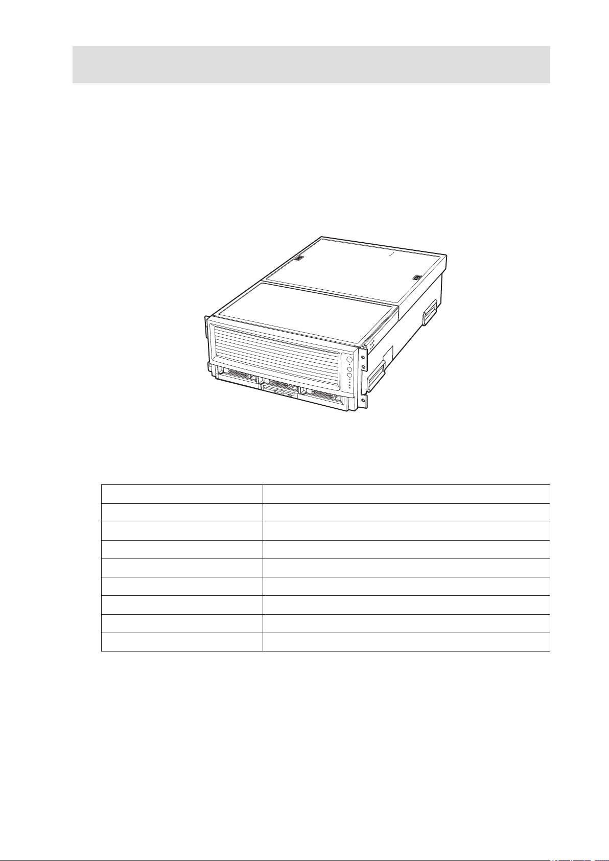
The MAXDATA PLATINUM 9000-4R as shown in Figure 1 is a compact, high-density rack-mount
server system with support for one to four Intel® Itanium® 2 processors and 32-GB DDR SDRAM
memory. The system is based on the Intel S870BN4 board set and the Intel® E8870 chipset. The
system supports hot-plug PCI and PCI-X add-in cards; hot-swap, redundant power supply modules;
hot-swap, redundant cooling fans; and hot-swap hard disk drives. The system also provides interlock
status LEDs for critical system interconnects. The system supports Symmetric Multiprocessing (SMP)
and a variety of operating systems. Table 1 presents an overview of the server system’s physical
characteristics.
Figure 1. MAXDATA PLATINUM 9000-4R Server Front View
Table 1. Server Physical Specications
Characteristic Specification
Height 178 mm (6.9 inches, 4U)
Width 445 mm (17.5 inches)
Depth 711 mm (28.0 inches)
Weight (max.) 48 kg (106 lbs)1
Required front clearance 76 mm cm (3 inches)
Required rear clearance 152 mm (6 inches)
Required side clearance 25 mm (1 inch)
Heat Dissipation 1500 W (5,100 BTU/hr)
1. The system weight listed above is an estimate for a fully configured system and will vary depending on the number of
peripheral devices and add-in cards as well as the number of processors and DIMMs installed in the system.
Page 16

16 System Description
17MAXDATA PLATINUM 90004R Server System
Chassis Description
The chassis provides a modularized processor/memory subsystem, I/O subsystem, and peripheral
bay. Other features are outlined in Table 2.
Table 2. Chassis Feature Summary
Feature Comment
Server
Configuration
• Stand-alone system including external I/O PCI slots and disk expansion as needs
grow
• Supports Intel® Itanium® 2 processors
• 32-GB Double Data Rate (DDR) Synchronous Dynamic Random Access Memory
(SDRAM) memory support with 2-GB DIMMs
Expansion
and Servicing
• Front access to hot-swap hard disk drives
• Three hot-swap 1-inch Ultra320 SCSI hard disk drives
• Rear access to hot-swap power supplies
• Two hot-swap 1200-W power supplies in a redundant (1+1, 220 V) configuration
with redundant power cords (one per power supply)
• Four top access hot-swap system fans in a redundant (3+1) configuration
• Dockable processor/memory subsystem, I/O subsystem and peripheral bay
• Dockable slim-line LS-240 and DVD/CD-ROM drives
• Interlock status indicator LEDs for major modulesEight 64-bit hot-plug PCI-X
slots
Management • Remote management through LAN or modem
• Emergency Management Port
• Intelligent Platform Management Interface (IPMI) 1.5 compliant
• Wired for Management (WfM) 2.0 compliant
• Remote diagnostics support through LAN or modem
Upgrades
• Field upgradeable to the next generation Itanium® processor family
• Multi-generational chassis
System-level
scalability
• Up to 32-GB DDR SDRAM
• One to four Intel
®
Itanium
®
2 processors
• External I/O (8 PCI slots) and disk expansion
• External SCSI connector
Page 17

17MAXDATA PLATINUM 90004R Server System
External Chassis Features
System controls and indicators are located in several places on the chassis as follows:
• Chassis front:
– Front panel: Front panel switches and LEDs
– Peripheral bay: Hard disk drive LEDs
– Processor/memory module: Subsystem serviceability LEDs
• Chassis back:
– Power supply modules (See Power Subsystem for details)
– Hot-plug Indicator Board (HPIB)
• Chassis top:
– I/O subsystem
– Fan bay (See Cooling Subsystem for details)
Each of these areas is discussed in this section.
Chassis Front
Figure 2 shows the front view of the chassis with the snap-on bezel in place. The bezel provides
access to the front panel board and the peripheral bay.
A
B
C
Figure 2. Chassis Front View
A. Bezel
B. Front Panel
C. Peripheral Bay
Front Panel
The front panel is located to the right of the processor/memory subsystem and provides user interface
for system management via switches and status indicatosr LEDs. The front panel also contains the
speaker. Figure 3 shows the control buttons and status indicators on the front panel. Table 3 describes
their features.
Page 18

18 System Description
19MAXDATA PLATINUM 90004R Server System
A
B
C
D
F
G
H
I
E
Figure 3. Front Panel Controls and Indicators
Table 3. Front Panel Control and Indicator Description
Item Feature Description
Switches
A. System ID Switch Toggle switch for blue System ID LEDs (the front panel system ID LED
is located inside the system ID switch). See E below for description of
LED operation.
B. Assert SDINT
(System Diagnostic
Interrupt) Switch
Asserts SDINT. This switch is accessible through a small opening and
requires a narrow tool to activate.
C. Reset switch Resets the system.
D. Power switch Toggles system power. A delay of ~5 seconds is required between
pressing the power switch to power down and then power up the
system.
LED Indicators
E. System ID (Blinking
or Solid Blue). The
system ID LEDs are
located inside the
system ID switch on
the front panel and
on the back panel
Identifies the system. The system ID is activated either by the system
ID switch or through server management software.
Pressing the system ID switch once turns on the LEDs solid blue.
Press the system ID switch again, the solid blue LEDs turn off.
Remove activation - LEDs turn on blinking for 4 minutes (max). The
system ID LEDs cannot be turned off by pressing the switch.
F. Main Power (Solid
or Blinking Green)
A continuously lit LED indicates the presence of DC power in the
system. The LED goes out when the power is turned off or the power
source is disrupted. Blinking Green indicates the system is in sleep
mode.
G. Power Fault (Solid
Amber)
Indicates any system power faults. Off indicates power is OK.
H. Cooling Fault (Solid
Amber)
Indicates any system cooling faults. Off indicates system
cooling is OK.
I. General Fault (Solid
amber)
Indicates a system failure. Off indicates system is OK.
Page 19
19MAXDATA PLATINUM 90004R Server System
Peripheral Bay
!
CAUTION
Removal of the LS240 and the DVD/CD drives requires removal of the peripheral bay from the chassis.
Therefore, the LS240 and the DVD/CD drives cannot be hot-swapped. Power must be removed from
the system when installing or removing these drives to avoid component damage.
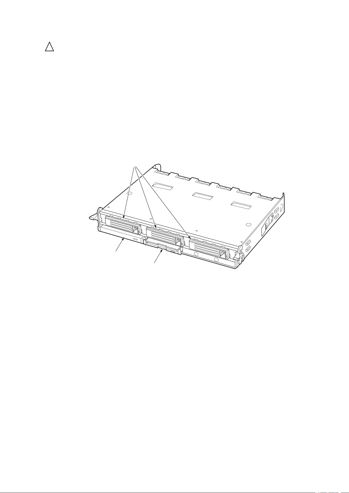
The peripheral bay consists of two sections:
• The hot-swap hard drive bay (upper section) supporting three 1-inch hot-swap Ultra320 SCSI
hard disk drives (A in Figure 4).
• The removable media drive bay (lower section) supporting:
– One -inch IDE DVD/CD-ROM (B in Figure 4)
– One -inch IDE LS-240 drive (C in Figure 4) or removable EMI Filler Panel (D in Figure 4).
A
B
C
Figure 4. Peripheral Bay
Page 20
20 System Description
21MAXDATA PLATINUM 90004R Server System
Hot-swap Hard Disk Drive Bay
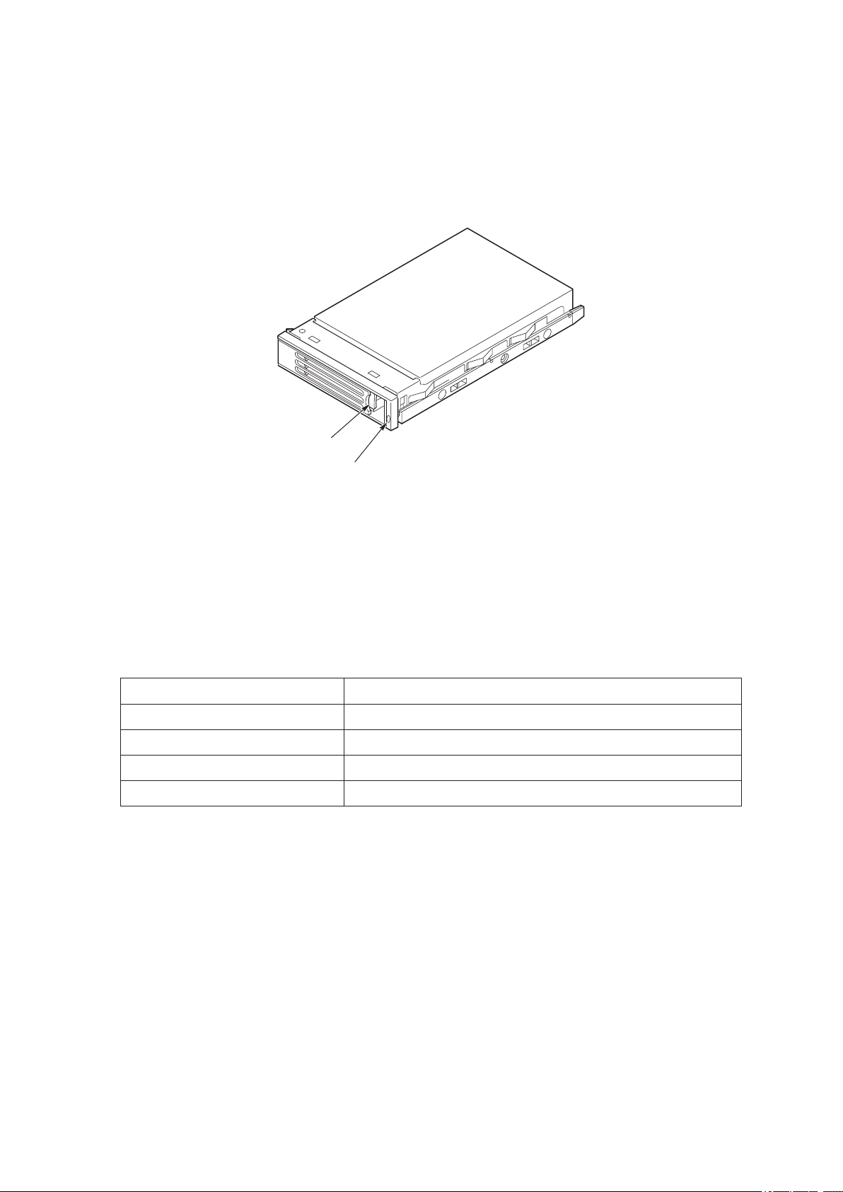
The hot-swap hard disk drive carrier (see Figure 5) is designed to accept 15,000-RPM (and slower)
Ultra320 SCSI technology SCA-type hard disk drives.
The peripheral bay is designed to support Low Voltage Differential (LVD) SCSI disk drives only. SingleEnded (SE) SCSI devices are not supported in the peripheral bay. SE drives are only supported on
the external SCSI connector.
A
B
Figure 5. Hard Disk Drive Carrier
A. Carrier latch
B. Status indicator
The carriers contain light-pipes that allow dual color LED indicators to show thsrough the bezel to
display hard disk drive status as described in Table 4.
Table 4. SCSI Hard Drive LED Details
Feature Description
Green, flashing Indicates the hard drive is active
Yellow/Green flashing Indicates a hard drive fault and hard drive is powered
Yellow/Blank flashing Indicates a hard drive fault and hard drive is not powered
Not illuminated Indicates no hard drive is installed in the bay
Page 21
21MAXDATA PLATINUM 90004R Server System
Removable Media Drive Bays
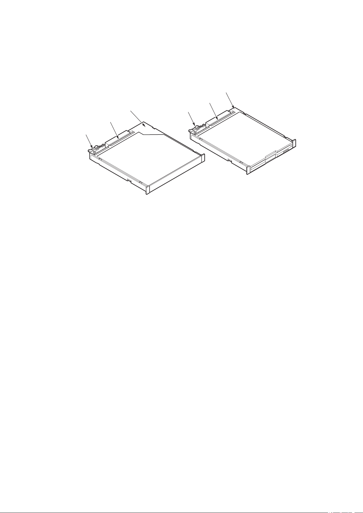
The slim-line LS-240 and DVD/CD-ROM drives and their adapter boards are installed in plastic carriers
(see Figure 6) and are inserted from the front of the removable media drive bay. You must switch off
system power and remove the peripheral bay to remove or install these drives. If the LS-240 is not
included with the server, then a ller panel must be used (see D in Figure 6).
A
C
B
A
C
B
Figure 6. DVD/CD-ROM and LS-240 Drive Carriers
DVD/CD-ROM LS-240 Floppy Disk Drive
A. Latch A. Latch
B. Adapter board with locking
connector
B. Adapter board with locking
connector
C. Plastic Carrier C. Plastic Carrier
SCSI Backplane Board
The SCSI backplane board mates with the midplane board connector. It contains three 80-pin Single
Connector Attachment (SCA)-2 connectors for hot-swap hard disk drives. The SCSI backplane board
performs the tasks associated with hot-swapping the hard disk drives and enclosure monitoring and
management. The features supported by the SCSI backplane board include the following:
• Monitoring the SCSI bus for enclosure services messages, and acting on them appropriately.
Examples of such messages include: activate a drive fault indicator; power down a drive that
has failed; and report SCSI backplane temperature.
• SAF-TE intelligent agent, which acts as proxy for “dumb” I2C devices (that have no bus
mastering capability) during intrachassis communications.
Page 22
22 System Description
23MAXDATA PLATINUM 90004R Server System
Processor/Memory Subsystem Serviceability Status Indicators
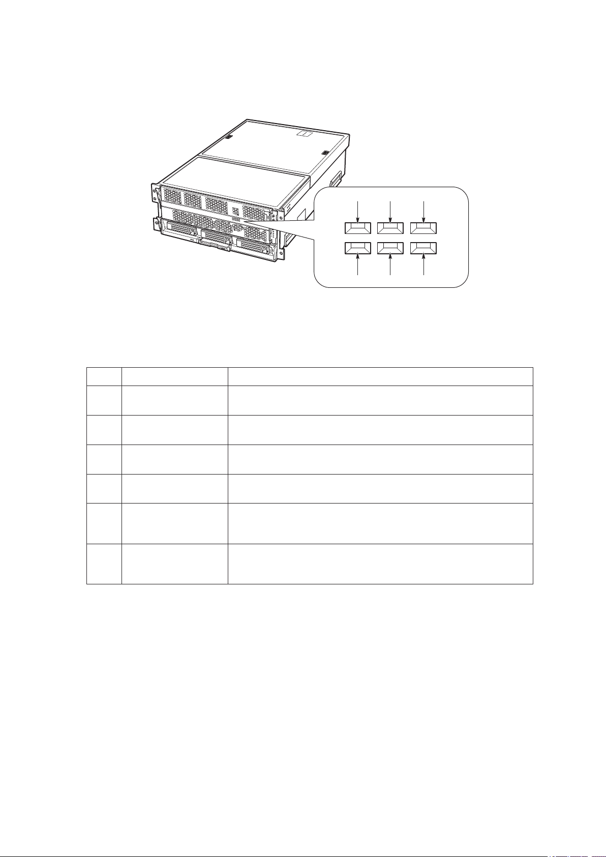
The serviceability status indicators contained in the processor/memory subsystem are shown in
Figure 7 and described in Table 5. To view these indicators, remove the front bezel.
A C E
B D F
Figure 7. Location of Processor/Memory Subsystem Serviceability Indicators
Table 5. Processor/Memory Subsystem Serviceability Indicator Details
Item Feature Description
A Processor 1
Present (green)
On – Processor 1 is present and installed properly
Off – Processor 1 not detected
B Processor 2
Present (green)
On – Processor 2 is present and installed properly
Off – Processsor 2 not detected
C Processor 3
Present (green)
On – Processor 3 is present and installed properly
Off – Processor 3 not detected
D Processor 4
Present (green)
On – Processor 4 is present and installed properly
Off – Processor 4 not detected
E Memory Board 1
Interlock to Processor
Board (green)
On – Memory board 1 is inserted properly into the processor board
Off – Memory board 1 to processor board interlock not detected
F Memory Board 2
Interlock to Processor
Board (green)
On – Memory board 2 is inserted properly into the processor board
Off – Memory board 2 to processor board interlock not detected
NOTE
Two additional LEDs (Green and Amber) and a switch appear on the left side of the processor board.
These components are not implemented in the MAXDATA PLATINUM 9000-4R Server system and
are not visible or accessible through the front bezel.
Page 23
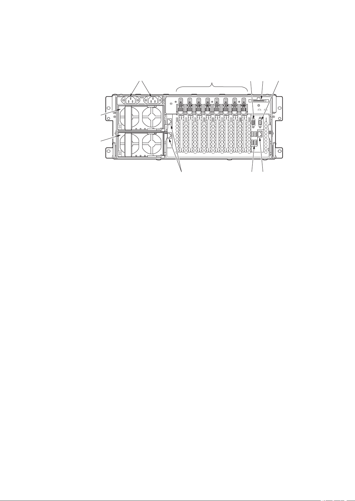
23MAXDATA PLATINUM 90004R Server System
Chassis Back
Figure 8 shows the features found on the chassis back panel including the I/O bay, the power supply
modules, and user-accessible connectors.
A C D E
FGH
I
B
J
Figure 8. Chassis Back Features
A .
AC input power connectors
B .
PCI Slots (All slots support hot-plug PCI add-in cards)
1
Slots 1 through 4 100-MHz, 64-bit PCI-X slot, half length
Slot 5 100-MHz, 64-bit PCI-X slot, full length
Slots 6 through 8 133-MHz, 64-bit PCI-X slot, full length
C .
Video port, standard VGA compatible, 15-pin connector
D .
External SCSI connector (optional)
2
E .
Serial port, 9-pin RS-232 connector
3
F .
Ethernet port, RJ45 connector
G .
Four USB ports, 4-pin connectors
H .
ICMB connectors in/out (optional
ICMB port 1, SEMCONN 6-pin connector
ICMB port 2, SEMCONN 6-pin connector
I .
Power supply 2
J .
Power supply 1
Notes: 1. PCI slots support 3.3 V signal adapter cards only.
2. External SCSI bus supports both LVDS and SE signals via the external SCSI connector.
3. Emergency Management Port (EMP) access is provided via shared serial port.
Page 24
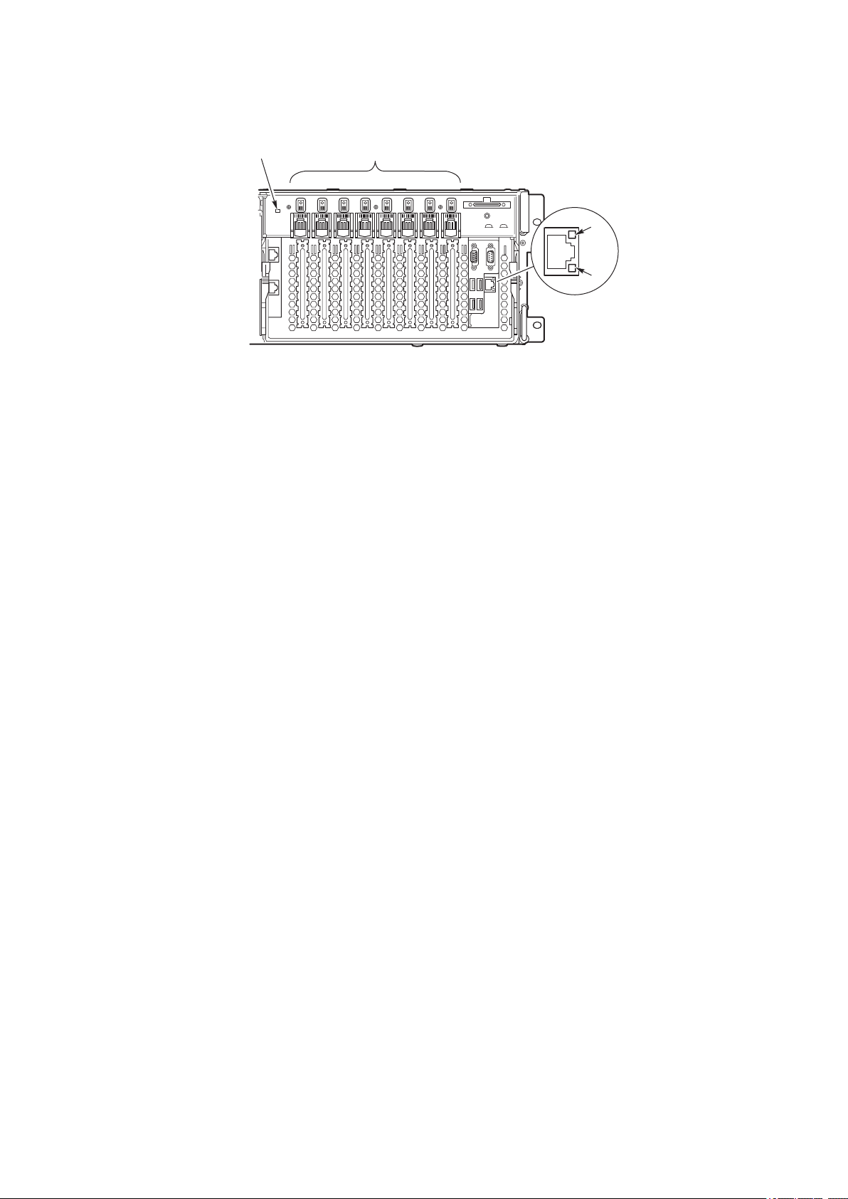
24 System Description
25MAXDATA PLATINUM 90004R Server System
Back Panel
Figure 9 shows the location of the indicators and controls found on the back panel.
A B
C
D
Figure 9. Back Panel View Showing Indicator and Switch Locations
System ID Indicator LED
A. System ID LED (blue) Identifies the system. The system ID LED is activated either
by the System ID switch on the front panel or through server
management.
Hot-plug PCI Add-in Card Switches and LEDs
B. Attention Switch Notifies PCI hot-plug system software (ACPI PHP ASL) that a PCI
hot-plug operation is about to take place.
WARNING: Verify in BIOS release notes that this feature is
supported before using the Attention button.
MRL (Manually-operated
Retention Latch) Switch
Disables power to the PCI slot if a PCI add-in card is present.
Green LED On – PCI slot is powered.
Off – PCI slot is powered down.
Amber LED On – PCI slot or card fault condition.
Ethernet Interface Status LED Indicators
C. Network Interface Status
LED (green)
Shows activity and status.
D. Network Interface Status
LED (yellow)
Shows activity and status.
Page 25

25MAXDATA PLATINUM 90004R Server System
Power Supply LED Indicators
Each power supply module has three status LEDs the location and operating conditions for which
are shown in Figure 10.
A CB
Figure 10. Power Supply Indicators
A. Power LED (green) On - indicates the presence of DC power in the system
Blinking - indicates the system is in ACPI sleep mode
Off - indicates the power is turned off or the power source is
disrupted
B. Failure LED (amber) Indicates a power supply failure
C. Predictive Failure LED (amber) Indicates a power supply failure is imminent
Table 6. Power Supply LED Status Indicators
A
(PWR)
Power Supply
(Green LED)
B
(FAIL)
Power Supply Fail
(Amber LED)
C
(PFAIL)
Predictive Failure
(Amber LED)
No AC power to all PSU OFF OFF OFF
No AC power to this PSU only or PS
failure
OFF OFF ON
AC present / Standby Output On Blinking OFF OFF
Power supply DC outputs ON and
OK
ON OFF OFF
Current limit ON OFF Blinking
Predictive failure ON Blinking/Latched OFF
NOTE
Proper system cooling requires that the power supply bay be lled either by two power supply
modules, or a power supply module and a ller panel.
Page 26

26 System Description
27MAXDATA PLATINUM 90004R Server System
Chassis Top
I/O Subsystem Serviceability Indicators
Figure 11 shows the I/O subsystem serviceability indicators. The indicators are located on the I/O board
and are visible through the system top cover via light pipes. The I/O serviceability indicators provide
system power, system reset, and interlock status for various subsystem and module connectors.
These LEDs are powered by standby voltage to provide status as long as AC power is supplied to
the system.
System In Reset
System Power Good
IO Bd/Midplane Interloc
k
IO Riser/IO Bd Interloc
k
Proc/Mem/CPU Bd Interloc
k
SCSI Bd/Midplane Interloc
k
Attention
OK
OK
OK
OK
OK
Figure 11. I/O Subsystem Serviceability Indicators
System In Reset (amber) On – system reset asserted
Off – system reset not asserted
System Power Good
(green)
On – system power within normal operational range
Off – system power failure
I/O Board to Midplane
Board Interlock (green)
On – I/O subsystem inserted properly into midplane board
Off – I/O subsystem to midplane board interlock not detected
I/O Riser to I/O Board
Interlock (green)
On – I/O riser inserted properly into I/O board
Off – I/O riser to I/O board interlock not detected
Processor/Memory/CPU
Board Interlock (green)
On – processor/memory subsystem inserted properly into midplane board
Off – processor/memory subsystem to midplane board interlock not detected
SCSI Board to Midplane
Board Interlock (green)
On – SCSI backplane board inserted properly into midplane board
Off – SCSI backplane board to midplane board interlock not detected
Page 27

27MAXDATA PLATINUM 90004R Server System
Internal Chassis Features
Power Subsystem
!
WARNING
Only qualied technical personnel should access the processor, memory, and non-hot-plug I/O
subsystem areas while the system is energized as some exposed circuits exceed 240 VA and may
cause burn injury if accidentally contacted.
The power subsystem can be congured as following:
• Two power supply modules installed, (1+1) redundancy at 220 VAC
• One power supply module installed, non-redundant at 220 VAC only
• Two power supply modules installed, non-redundant for 120 VAC
The power subsystem consists of the following:
• Power supply modules
• Plug-in DC-to-DC converters
• Power pods (located adjacent to the processors on processor board)
• The power distribution board
Power Supply Modules
The power supply modules are Server System Infrastructure (SSI) compliant, universal AC input with
Power Factor Correction (PFC) Distributed Power Supplies (DPS). The power supply modules are rated
at 1200 W over an input range of 180-264 VAC, and at 700 W over an input range of 90-132 VAC.
One power supply module connected to 220 VAC is capable of handling the worst-case power
requirements for a fully congured system: four processors, 32 GB of memory, eight PCI add-in
cards, three hard disk drives, a DVD or CD drive, and an LS-240 drive.
The power supply has two DC outputs: 48 V (main) and 12 V (standby). The 48 V main power is
distributed throughout the server and is converted locally at point-of-load using either embedded or
plug-in DC-to-DC converters.
In an N+1 conguration the 48 VDC outputs have active (forced) current sharing and 12 VDCSB outputs
have passive current sharing.
The two externally enabled outputs have the following ratings:
• +48 VDC at: 24.0 A @HI line /13.5 A @LO line
• +12 VDCSB at: 4 A @any line
Page 28

28 System Description
29MAXDATA PLATINUM 90004R Server System
Redundant AC Power Source Operation
Each power supply module requires one power cord to supply AC power to the system. When two
power supply modules and two power cords are installed, the system supports (1+1) power cord
redundancy at 220 VAC. This feature allows the system to be powered by two separate AC sources.
In this conguration, the system continues to operate without interruption if one of the AC sources
fails.
Plug-in DC-to-DC Converters
Two types of plug-in DC-to-DC converters are used in the system:
• 5 V output
• Voltage ID (VID) (2.5 or 3.3 V output)
A control bit set by the board determines output voltage on the VID DC-to-DC converters. The T-DCto-DC converters contain an LED for failure indication.
The processor board supports three VID T-DC-to-DC converters (one 3.3 V and two 2.5 V).
The I/O board supports two 5 V and two VID (3.3 V) T-DC-to-DC converters. Each T-DC-to-DC converter
powers a separate plane on the board; therefore all DC-to-DC converter slots must be populated.
Processor Power Pods
Dedicated power pods supply power to each processor. The input connector of the power pod is
connected to the 48 V power on the processor board via a short cable. The output connector of the
power pod mates directly with the processor package.
The Power Distribution Board
The power distribution board supplies 48 V main and 12 V standby power to all server system
components.
Cooling Subsystem
!
CAUTION
The chassis top cover must be installed and closed for proper system cooling. Additionally, cooling
components must be hot-swapped within a limited time period. This time period applies only to the
time that the cooling component is physically removed, not from the time of failure.
The cooling subsystem consists of a hot-swap, redundant (3+1) system fan array installed in the fan
bay, and the fans in the power supply modules. In the event of a cooling component failure, system
cooling is maintained and the system continues to operate while the component is being hot-swapped.
All system fans have tachometer output and internal speed control.
Page 29
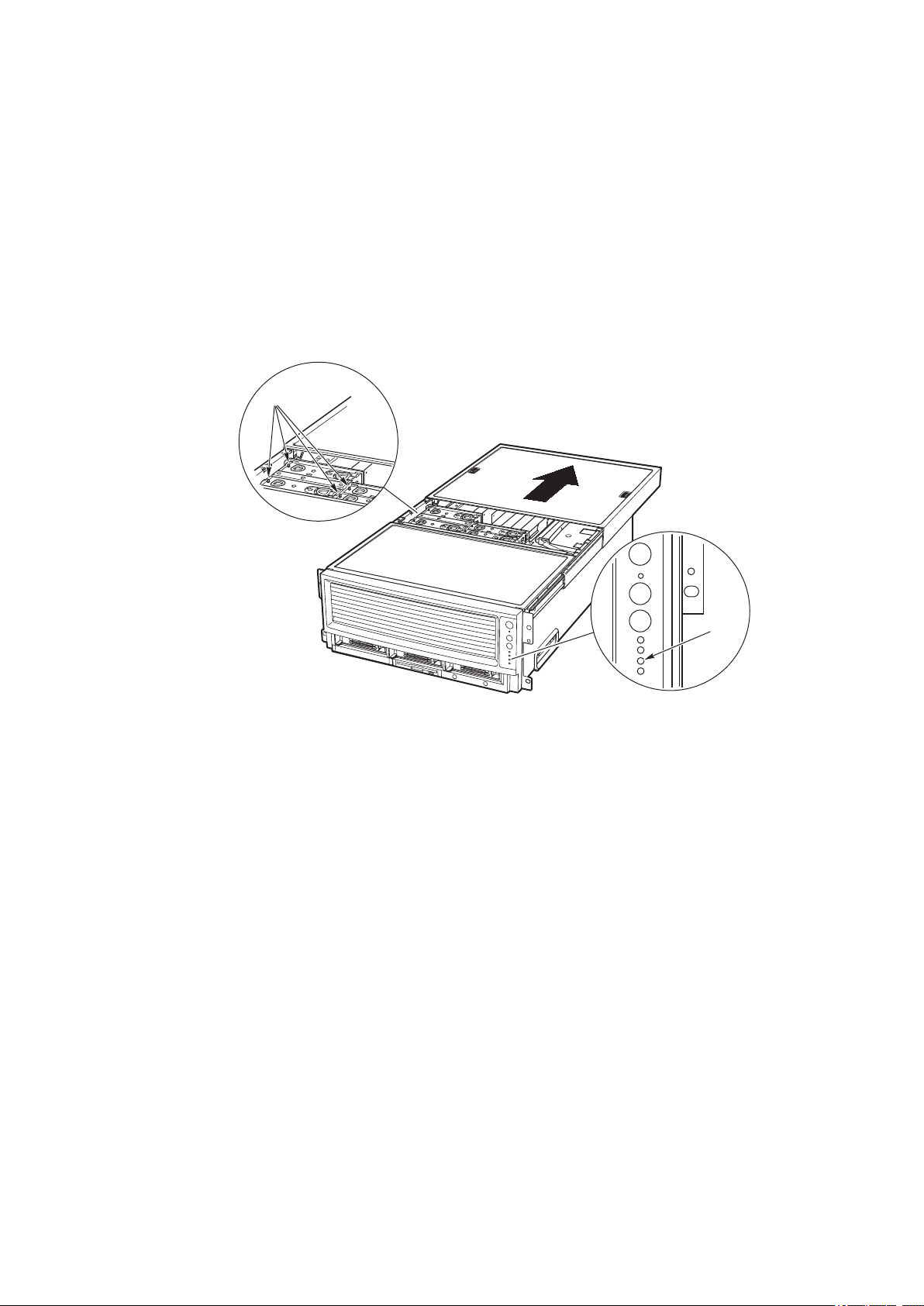
29MAXDATA PLATINUM 90004R Server System
NOTE
The server supports only a fully populated system fan conguration. All congurations are redundant
except those with only one power supply installed.
A series pair of 120 x 38 mm system fans cools the processors and part of the I/O subsystem. The
rest of the processor/memory and I/O subsystem components, hard drives and power supplies are
cooled by a series pair of 120 x 25 mm system fans along with the power supply fans. Hot-swap
system fans drop into the fan bay and interface with connectors on the I/O board.
The fan bay also contains the individual fan status indicators that can be seen when the back top
chassis cover is open. A system fan failure is indicated by two LEDs, the LED on the corresponding
fan (A in Figure 12), and the Cooling Fault LED on the front panel (B in Figure 12).
A
B
Figure 12. Fan Status Indicators
Page 30

30 31MAXDATA PLATINUM 90004R Server System
Page 31
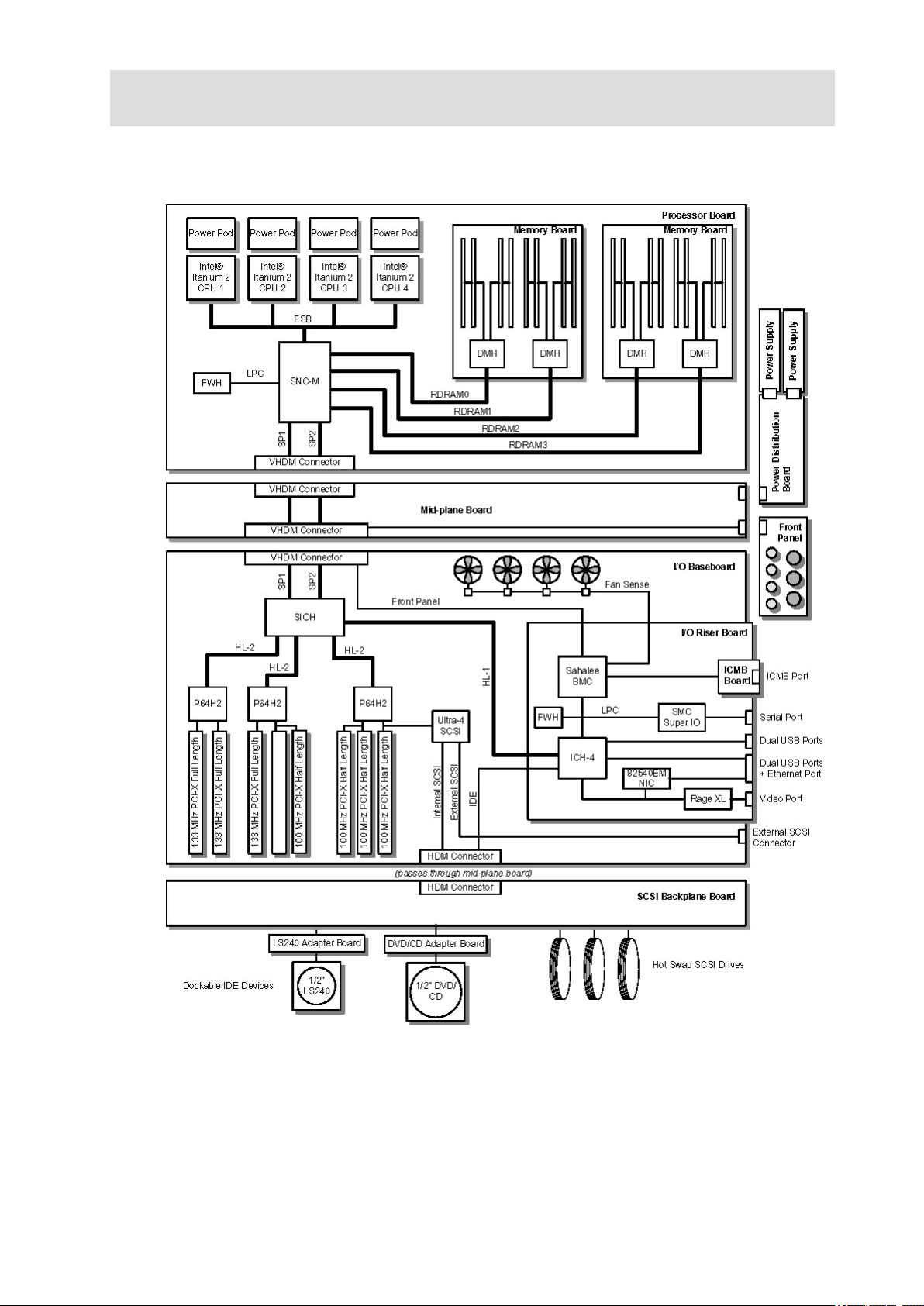
2 Board Set Description
Figure 13 displays a block diagram of the system and the board set within the system.
Figure 13. Server System Block Diagram
Page 32

32 Board Set Description
33MAXDATA PLATINUM 90004R Server System
System Board Set
This section highlights the main features of the board set. The board set contains the following:
• Processor board
• Two memory boards
• I/O board
• I/O riser card
• Midplane board
In addition, the server contains the following system boards:
• Front panel board
• SCSI backplane board
• Power distribution board
• PCI HPIB
• Peripheral adapter boards
• ICMB Board (optional)
Major components of the board set include:
• Intel® Itanium® 2 processors
• Intel® E8870 chip set
• High-capacity DDR SDRAM memory
• High-bandwidth I/O subsystem supporting PCI and PCI-X
Page 33

33MAXDATA PLATINUM 90004R Server System
Processor Board
The processor board contains sockets for installing up to four Intel® Itanium® 2 processors and supports
up to four power pods. It also accepts the memory boards.
The processor board and memory boards are installed horizontally in the processor/memory module.
The processor/memory module docks into the front of the chassis and mates with the midplane board
mounted vertically in the middle of the chassis.
The processor board supports the following:
• Sockets for up to four Intel® Itanium® 2 processors. Two of the processor sockets are mounted
on the secondary side of the processor board.
• Provision for up to four 48 V DC-to-DC converter power pods, one for each Intel® Itanium® 2
processor.
• DC-to-DC voltage converters:
– Two 48 V to 2.5 V plug-in DC-to-DC converters for DDR memory support
– One 48 V to 3.3 V plug-in DC-to-DC converter
• Embedded regulators:
– 3.3 V to 1.2 V
– 3.3 V to 1.5 V
– 3.3 V to 1.8 V
– 1.8 V to 1.3 V linear regulator
• One SNC-M component of the Intel® E8870 chip set.
• Three Firmware Hubs (FWH) for BIOS and system conguration utility (SCU) software.
• Two memory board connectors that support two Rambus channels each. One memory
connector is mounted on the secondary side of the processor board.
• One VHDM 360-pin connector for I/O connections.
• One debug port for use with an In-Target Probe (ITP) (debug only).
• Two I2C system management buses (SMBus).
• Serviceability LEDs.
NOTE
The processor board also contains a switch and two LEDs on the front left corner of the primary side
of the board that are not used in the MAXDATA PLATINUM 9000-4R Server system.
Page 34

34 Board Set Description
35MAXDATA PLATINUM 90004R Server System
Processor Overview
Each Intel® Itanium
®
2 processor plugs into a 700-pin Zero Insertion Force (ZIF) socket. Each processor
is powered by a 48 V power pod located adjacent to the processor on the processor board. Attached
to the top of each processor is a heat sink that dissipates thermal energy.
Memory Boards
The processor board is designed to support two memory boards (both of which must be installed for
the system to operate). The memory boards are installed on the primary and secondary side of the
processor board assembly.
The main components of the memory boards is described as follows:
• Eight 184-pin, DDR-SDRAM DIMM sockets support up to 16 GB of memory using eight 2 GB
DIMMs per memory board for a total of 32 GB per system.
• Two DMH (DDR Memory Hub) components of the E8870 chip set. This allows two Rambus
channels from the E8870-memory controller (SNC-M) to be extended to four DDR channels on
the memory boards. The Rambus channel supports 400 MHz operation and the DDR channels
support 100 MHz operation.
• An integrated 2.5 V to 1.25 V DC-to-DC converter provides voltage for DDR signal termination.
• I2C logic.
• Field Replaceable Unit (FRU) device ID accessed through a private I2C bus.
• Voltage/temperature sensors.
DIMMs must be installed on a memory board in groups of four (a group of four constitutes a row)
as shown in Installing DIMMs“.
!
CAUTION
DIMMs should only be installed, removed, or replaced by a technically qualied person.
!
CAUTION
The system does not support mixed-sized DIMMs or DIMMs from different vendors within the same
row.
NOTE
The BIOS automatically detects, sizes, and initializes the memory array, depending on the type,
size, and speed of the installed DIMMs. The BIOS reports memory size and allocation to the system
through conguration registers.
Page 35

35MAXDATA PLATINUM 90004R Server System
I/O Board
The I/O board is installed horizontally in the I/O bay. The I/O riser card plugs into a connector on the
I/O board. The I/O provides the following features:
• Intel® E8870 chip set with Scalability Port system interface
• Six functionally independent Peripheral Component Interconnect (PCI) bus segments
• Three hot-plug 133-MHz, 64-bit PCI-X slots
• Five hot-plug 100-MHz, 64-bit PCI-X slots
• Integrated dual channel LSI 53C1030 Ultra320 Low Voltage Differential SCSI (LVDS) controller
• I/O riser support connector for I/O interface
• On-board power conversion from 48 V bulk power
• System reset and clock generation circuits
• I2C server management interface
• Redundant hot-plug system fan interface
I/O Riser
To conserve space on the I/O board, most system I/O and server management functions have been
placed on the I/O riser card that plugs into the I/O board. The I/O connectors include video, serial,
Local Area Network (LAN), and Universal Serial Bus (USB). The I/O riser:
• Contains an IDE bus controller and connector. The IDE bus is routed to the I/O board where it is
further routed to the midplane board’s disk bay connector.
• Converts 12 V STDBY (standby) to +5 V STDBY and +3.3 V STDBY and supplies them to the I/O
board.
• Mates directly onto the I/O board and together they contain all of the I/O interfaces for the
board set.
The I/O riser provides the following features:
• One I/O Control Hub 4 (ICH4) component
– Four Universal Serial Bus (USB) ports
– One IDE interface routed through the I/O board connector
• Network Interface Card (NIC) Intel® 82540EM 10/100/1000 Ethernet controller
– Ethernet port with I2C support
• Low Pin Count (LPC) Super I/O
– One serial port
• 3 MB of ash memory
• Server management controller
• Integrated Intelligent Chassis Management Bus (ICMB)
• Integrated Rage XL video controller and memory
– Video port
– Power control - Advanced Configuration and Power Interface (ACPI)
• Speaker control
• Integrated standby voltage DC-to-DC converters generating 3.3 V standby and 5 V standby
Page 36

36 Board Set Description
37MAXDATA PLATINUM 90004R Server System
Midplane Board
The passive midplane board contains the following features:
• VHDM connectors for the processor/memory subsystem and the I/O subsystem
• An HDM connector that routes the SCSI bus, two IDE busses, and miscellaneous signals
between the I/O board and the SCSI backplane
• Routing of four scalability ports
• 48 V power distribution
• 12 V standby distribution
• 3.3 V standby distribution
• 12 V distribution from the SCSI backplane board to the I/O board and power distribution board
• Blind-mate power distribution board connector
• Blind-mate front panel connector
Front Panel Board
The front panel board contains switches, LEDs, and the speaker for system interface.
SCSI Backplane Board
The SCSI backplane board supports three LVDS hard drives. Its features include:
• Three SCA connectors for hot-swap 1-inch SCSI hard drives
• One blind-mate connector for dockable slim-line IDE LS240 device
• One blind-mate connector for dockable slim-line IDE DVD or CD device
• SCSI accessed fault-tolerant enclosures (SAF-TE) logic
• 48 V to 12 V integrated DC-to-DC converter
• 12 V to 5 V integrated DC-to-DC converter
• 5 V to 2.5 V linear regulator
Peripherals
The server connects to supported peripheral devices through interfaces located on the I/O Board.
The Super I/O on this board provides four USB ports, an Ethernet port, a serial port, an external SCSI
connector (optional), a VGA video output port, and in and out ICMB connectors (optional). .
External SCSI Connector (Optional)
An external SCSI connector is available as an option. A cable runs from the I/O board to the external
SCSI connector installed on the back panel.
The I/O board contains two Ultra320 compliant SCSI channels. One channel is used internally while
the other is for external system use. While the internal channel supports only Low Voltage Differential
(LVD) signaling, the external channel supports both LVD and SE (single-ended) signaling. With LVD
signaling, the channels can each support a maximum data rate of 320 MB/sec.
NOTE
The internal SCSI signal is routed to the midplane board’s disk bay connector to interface with internal
SCSI devices. There is an optional connector on that bus that allows an external SCSI controller to
drive the internal bus.
Page 37

37MAXDATA PLATINUM 90004R Server System
Add-In Board Slots
The I/O board has three 64-bit/133 MHz hot-plug PCI-X and ve 64-bit/100 MHz PCI-X expansion slots
contained in the following three PCI segments:
• P64H2,0 provides for PCI-X slots 1 through 3 (all 100 MHz) and the dual channel LVDS
controller
• P64H2,1 provides for PCI-X slots 4 through 6 (two 100 MHz and one 133 MHz)
• P64H2,2 provides for PCI-X slots 7 and 8 (both 133 MHz)
Video
The onboard, integrated ATI RAGE XL 64-bit SVGA chip contains an SVGA controller that is fully
compatible with industry video standards. The system comes with 8 MB of 10-nanosecond onboard
video memory.
The video controller supports pixel resolutions of up to 1600 x 1200 and up to 16.7 million colors. The
controller also provides hardware accelerated bit block transfers of data.
The SVGA controller supports analog VGA monitors (single and multiple frequency, interlaced and
noninterlaced) with a maximum vertical retrace noninterlaced frequency of 100 Hz.
The video connector is located on the I/O riser.
SCSI Controller
A LSI 53C1030 Ultra3 SCSI chip is a highly integrated bus master, dual-channel SCSI I/O processor for
SCSI initiator and target applications. The chip supports dual channel, Ultra3 (Fast-80) SCSI functionality.
This device interfaces the PCI bus to two Ultra3 SCSI buses. The 53C1030 is a fully autonomous
device, capable of managing multiple I/O operations and associated data transfers from start to nish
without host intervention. The 53C1030 provides power management feature support in accordance
with the PCI Bus Power Management Interface Specication.
ICH4 IDE Controller
The ICH4 IDE controller is a multifunction device on the I/O Board that acts as a PCI-based Fast IDE
controller. The device controls the following:
• PIO and IDE DMA/bus master operations
• Mode 4 timing
• Transfer rates up to 22 MB/sec (33 MB/sec using ultra DMA transfers)
• Buffering for PCI/IDE burst transfers
• Master/slave IDE mode
Page 38

38 Board Set Description
39MAXDATA PLATINUM 90004R Server System
Server Management
The server management features are implemented using two micro controllers: the Baseboard
Management Controller (BMC) on the I/O board and the QLogic GEM359 SCSI hot-swap controller
on the SCSI backplane board. The ICMB controller is integrated in the BMC and provides an interface
to the external ICMB via the ICMB board.
The rmware for the BMC of each micro controller is eld-upgradeable using the Firmware Update
utility. For information on the Firmware Update Utility, refer to “Running the Firmware Update Utility”
The GEM359 rmware can be updated using a separate utility.
Baseboard Management Controller (BMC)
The Baseboard Management Controller (BMC) and its associated circuitry reside on the I/O riser card.
The BMC autonomously monitors system platform management events and logs their occurrences in
the non-volatile System Event Log (SEL). This includes events such as over-temperature and over-voltage
conditions, and fan failures. The BMC can also provide the interface to the monitored information so
system management software can pole and retrieve the present status of the platform.
The BMC also provides the interface to the non-volatile ‘Sensor Data Record (SDR) Repository’.
Sensor Data Records provide a set of information that system management software can use to
automatically congure itself for the number and type of IPMI sensors (such as temperature and
voltage sensors) in the system.
The following is a list of the major functions of the BMC:
• System power control
• Platform Event Paging (PEP) / Platform Event Filtering (PEF)
• Power distribution board monitoring
• Temperature and voltage monitoring
• Fan failure monitoring
• Processor presence monitoring (no processors installed)
• Interlock monitoring
• Speaker ‘Beep’ capability on standby and when system is powered up
• Intel® Itanium® 2 processor SEEPROM interface (for processor information ROM [PIROM] and
scratch EEPROM access)
• Processor temperature monitoring
• Hot-plug PCI slot status reporting
• Processor core ratio speed setting
• Chassis general fault light control
• Chassis cooling failure light control
• Chassis power fault light control
• Chassis power light control
• Chassis ID LEDs control
• System Event Log (SEL) interface
• Sensor Data Record (SDR) repository interface
• SDR/SEL timestamp clock
• Board set FRU information interface
• Fault resilient booting
• System management watchdog timer
Page 39

39MAXDATA PLATINUM 90004R Server System
• Front panel system diagnostic-interrupt handling
• Platform Management Interruption (PMI) / System Diagnostic Interrupt (SDI) status monitor
• Event receiver
• System interface to the IPMB (via system interface ports)
• IPMI Management Controller Initialization Agent (MCIA)
• Emergency Management Port (EMP) interface
• Serial/modem and LAN alerting
In this platform, the BMC also plays the role of the chassis bridge controller, thus providing integrated
ICMB support. ICMB transports server management information between various chassis in a cluster
conguration that can contain multiple servers and peripherals.
QLogic GEM359 SCSI Hot-swap Controller
The QLogic GEM359 Hot-swap Controller resides on the SCSI backplane board. The primary functions
of the GEM359 are as follows:
• Implements the SAF-TE command set
• Controls the SCSI Hard Drive fault LEDs
• Provides a path for management information via the SCSI
• Retrieves hard disk drive fault status, SCSI backplane temperature, and fan failure information
via IPMB
• Queries the status of the power distribution board by retrieving information from the BMC
via IPMB
• Controls hard disk drive power-on and power-down, facilitating hot-swapping
Page 40

40 41MAXDATA PLATINUM 90004R Server System
Page 41

3 Conguration Software and Utilities
Power-on Sequence and Power-on Self-Test (POST)
Turning on the system causes POST to run and control to pass to the Boot Manager. From the Boot
Manager, you can choose to invoke the Extensible Firmware Interface (EFI) Shell or you can choose
to go to the Boot Maintenance Menu. For information on the EFI Shell, refer to “The Extensible
Firmware Interface (EFI) Shell”.
Follow these steps to power up the MAXDATA PLATINUM 9000-4R Server:
1. Press the power button on the front control panel. Pressing this button causes the server fans
to start up and POST to begin running. You can monitor boot progress on the video display on a
monitor attached to the system.
2. POST, which is stored in ash memory, begins running. POST checks the drive carriers,
processors, memory, keyboard, and most installed peripheral devices. During the memory test,
POST displays the amount of memory it is able to access and test. The length of time needed
to test memory depends on the amount of memory installed.
3. Video appears on the monitor attached to the system and begins to display boot progress. The
AMI BIOS banner displays the loaded versions of the BIOS, PAL, SAL, and EFI.
4. POST concludes and passes control to the boot manager.
5. From the boot manager, you can use arrow keys to highlight the option that invokes the EFI
shell operating system (if installed), or you can highlight and select the boot maintenance
menu. Selecting the boot maintenance menu lets you congure boot options and other boot
environment variables. Booting to the EFI shell causes the following prompt to appear:
Shell>
6. When you see this prompt, you can load and start an operating system.
The Extensible Firmware Interface (EFI) Boot Manager
The EFI boot manager allows you to control the server’s booting environment. Depending on how
you have congured the boot options, after the server is powered up the boot manager presents
you with different ways to bring up the system. For example, you can boot to the EFI Shell, to an
operating system located on the network or residing on media in the server, or to the Boot Maintenance
Menu.
• EFI Shell: A simple, interactive environment that allows EFI device drivers to be loaded, EFI
applications to be launched, and operating systems to be booted. The EFI shell also provides a
set of basic commands used to manage les and the system environment variables. For more
information on the EFI Shell, refer to “The Extensible Firmware Interface (EFI) Shell”.
• Boot Options: Files that you include as boot options. You add and delete boot options by using
the Boot Maintenance Menu. Each boot option species an EFI executable with possible
options. For information on the Boot Maintenance Menu options, refer to Table 7.
• Boot Maintenance Menu: A menu of items allowing you congure boot options and other boot
environment variables. Table 7 describes each menu item in the Boot Maintenance Menu.
Page 42

42 Configuration Software and Utilities
43MAXDATA PLATINUM 90004R Server System
Table 7. Boot Maintenance Menu Options
Option Description
Boot from a File Automatically adds EFI applications as boot options or allows you to
boot from a specific file.
When you choose this option, the system searches for an EFI directory
in all EFI System Partitions in the system. For each EFI directory the
system finds, it searches through that directory’s subdirectories.
Within each subdirectory, the system looks for the first file that is an
executable EFI Application. Each file that meets this criterion can be
automatically added as a boot option. In addition, legacy boot options
for A: and C: are also added if those devices are present.
Using this option, you can also launch a specific application without
adding it as a boot option. In this case the EFI Boot Manager searches
the root directories of all of the EFI System Partitions present in the
system for the specified EFI Application.
To boot from a file:
• At the menu, select Boot from a File Option with the arrow key.
• Hit the <Enter> key to select.
• Select the EFI file to boot from with the arrow key.
• Hit <Enter> to select.
Add a Boot Option Adds a boot option to the EFI Boot Manager. You specify the option by
providing the name of the EFI application. Along with the name you
can also provide either ASCII or UNICODE arguments the file might
use.
Given the EFI application name and any options, the EFI Boot
Manager searches for the executable file in the same partitions and
directories as described in “Boot from a File” option. When the file is
found, it is executed.
To add a boot option:
• At the menu, select Add Boot Option with the arrow key.
• Hit the <Enter> key to select.
• Type in the name of the EFI application to add and hit <Enter>.
• Select Save to NVRAM.
• Select Exit to return to the Boot Manager.
Delete Boot Options This feature allows you to delete a specific boot option or all boot
options.
To delete boot options:
• At the menu, select Delete Boot Option with the arrow key.
• Hit the <Enter> key to select.
• Select the boot option to delete with the arrow key.
• Hit <Enter> to select.
• Enter <Y> to confirm.
• Select Save to NVRAM.
• Select Exit to return to the Boot Manager.
Change Boot Order This feature allows you to control the relative order in which the EFI
Boot Manager attempts boot options. For help on the control key
sequences you need for this option, refer to the help menu.
To change the boot order:
• At the menu, select Change Boot Order with the arrow key.
• Select the Option to move with the arrow key.
• Hit <u> to move up in the boot order.
• Hit <d> to move down in the boot order.
• Select Save to NVRAM.
• Select Exit to return to the Boot Manager.
continued
Page 43

43MAXDATA PLATINUM 90004R Server System
Table 7. Boot Maintenance Menu Options (continued)
Option Description
Manage BootNext Setting This feature allows you to select a boot option to use one time (the
next boot operation).
To manage boot next setting:
• At the menu, select Manage Boot Next Setting with the arrow key.
• Select the Option to boot next with the arrow key.
• Hit <b> to make this option the next boot option.
• Hit <r> to reset.
• Select Save to NVRAM.
• Select Exit to return to the Boot Manager.
Set Auto Boot Timeout This feature allows you to define the value in seconds that pass
before the system automatically boots without user intervention.
Setting this value to zero disables the timeout feature.
To set auto boot timeout:
• At the menu, select Set Auto Boot Timeout with the arrow key.
• Three options are available.
• Select the Choose Value option with the arrow key and enter a
value of “0” to disable auto boot.
• Select the Delete option with the arrow key and select the Delete
setting with the arrow key and hit <Enter>.
• Choose a time out value of 65535 (0xFFFF) to allow you to press
any key while booting to EFI to disable timeout.
Select Console Output
Device
This feature allows you to select the device that the console output is
sent to.
To select the console output device:
• At the menu, select Manage Boot Next Setting with the arrow key.
• Select the Option to boot next with the arrow keyHit <b> to make
this option the next boot option.
• Hit <r> to reset.
• Select Save to NVRAM.
• Select Exit to return to the Boot Manager.
Select Console Input
Device
This feature allows you to select the device that the console receives
input from.
To select the console input device:
• At the menu, select Manage Boot Next Setting with the arrow key.
• Select the Option to boot next with the arrow key.
• Hit <b> to make this option the next boot option.
• Hit <r> to reset.
• Select Save to NVRAM.
• Select Exit to return to the Boot Manager.
Select Standard Error
Device
This feature allows you to select the standard error device.
To select the standard error device:
• At the menu, select Manage Boot Next Setting with the arrow key.
• Select the Option to boot next with the arrow key.
• Hit <b> to make this option the next boot option.
• Hit <r> to reset.
• Select Save to NVRAM.
• Select Exit to return to the Boot Manager.
Cold Reset Performs a platform-specific cold reset of the system. A cold reset
means a full platform reset.
To perform a cold reset:
• At the menu, select Set Auto Boot Timeout with the arrow key.
• Hit <Enter>.
• The system resets.
Exit Returns control to the EFI Boot Manager main menu. Selecting
this option displays the active boot devices, including a possible
integrated shell.
Page 44

44 Configuration Software and Utilities
45MAXDATA PLATINUM 90004R Server System
The Extensible Firmware Interface (EFI) Shell
The EFI Shell is an EFI application that allows other EFI applications to be launched, EFI device drivers
to be loaded, and operating systems to be booted. The combination of the EFI rmware and the
EFI Shell provides an environment that can be modied to easily adapt to many different hardware
congurations.
The EFI shell also provides a set of basic commands used to manage les and EFI NVRAM shell
and boot variables. A list of these basic commands is shown in Table 8. A more detailed description
of the commands is available on the EFI website. To obtain the document, navigate to the http:
//developer.intel.com/technology/e URL and click on the Tools hyperlink. Next, click on “EFI Sample
Implementation 1.10.14.60” to download the les to your hard drive. After downloading the sample,
locate the Microsoft® Word le named “EFI1.1ShellCommands.doc.” Descriptions of the EFI shell
commands are also available when operating in the EFI Shell by typing “help” and hitting the <Enter>
key.
In addition to the standard shell commands available in the EFI Shell, the EFI environment allows you
to create your own shell commands and EFI applications. For detailed information about the EFI Shell,
its commands, and the ability to develop within the environment, refer to the EFI Developer’s Guide.
To obtain the document, navigate to the http://developer.intel.com/technology/e URL and click on
the Tools hyperlink. Next, click on “EFI Sample Implementation Version 1.02” to download the les to
your hard drive. After downloading the sample, locate the Microsoft® Word le named “E_dg.doc”.
To develop your own shell commands, download the EFI Application Toolkit from the Tools hyperlink
on the following website:
http://developer.intel.com/technology/e
Table 8. EFI Shell Commands
Command Description
<drive_name>: Changes drives. For example, entering fs0: and pressing the
<Enter> key changes the drive to the LS-240 drive
alias [-bdv] [sname] [value] Sets or gets alias settings
attrib [-b] [+/- rhs] [file] Views or sets file attributes
bcfg -? Configures boot driver and load options in EFI NVRAM
botmaint Launches Boot Maintenance Manager
break Executes a breakpoint
cd [path] Changes the current directory
cls [background color] Clears the screen
comp file1 file2 Compares two files
connect [-r] [-c] Handle#
DeviceHandle# DriverHandle#
Binds the EFI driver to a device and starts the driver
cp [-r] file [file] ... [dest] Copies files and directories, [-r] = recursive
date [mm/dd/yyyy] Gets or sets the date
dblk device [Lba] [Blocks] Performs a hex dump of BlkIo Devices
devices [-b] [-1XXX] Displays devices
devtree [-b] [-d] Displays device tree
dh [-b] [-p prot_id] | [handle] Dumps handle information
continued
Page 45

45MAXDATA PLATINUM 90004R Server System
Table 8. EFI Shell Commands (continued)
Command Description
disconnect DeviceHandle#
[DriverHandle# [ChildHandle#]
Disconnects device from driver
dmem {address] [size] [;MMIO] Displays the contents of memory
dmpstore Dumps the variable store
drivers [-b] [-lXXX] Displays drivers
drvcfg [-c] [-lXXX] [-f] [-v] [-s] Invokes the driver configuration protocol
drvdiag [-c] [-lXXX] [-s] [-e] [-m] Invokes the driver diagnostics protocol
echo [[-on | -off] | [text] Echoes text to the standard output device or toggles script
echo
edit [filename] Opens the text editor allowing you to create or edit a file
eficompress infile outfile Compresses an EFI file
Efidecompress infile outfile Decompresses an EFI file
endfor Provides a delimiter for loop constructs (scripts only)
endif Provides a delimiter for IF THEN constructs (scripts only)
for var in <set>
goto label Makes batch file execution jump to another label
guid [-b] [sname] Dumps known guid ids
help [-b] [internal_command] Displays help information
hexedit [[-f]FileName|[-d DiskName
Offset Size]|[-m Offset Size]]
Edits in HEX mode
if [not] condition then Provides conditional constructs (scripts only)
load driver_name Loads a driver
loadbmp [-c] [-t] [-i[UGA Instance]]
file
Displays a bitmap file on the screen
loadpcirom romfile Loads a PCI option ROM
ls [-b] [dir] [dir] ... Obtains directory listings
map [-bdvr] [sname[:]] [handle] Maps sname to device path
mem [address] [size] [;MMIO] Dumps Memory or Memory Mapped IO
memmap [-b] Dumps memory map
mkdir dir [dir] Creates a new directory
mm address [Width] [;Type] [n] Memory Modify: type = Mem, MMIO, IO, PCI, [n] for non
interactive mode when inside a .nsh file
mode [col row] Sets or gets the current graphics mode
mount BlkDevice [sname[:]] Mounts a file system on a block device
mv [src…] [dst] Move one or more files/directories to destination
pause Prompts to quit or continue (scripts only)
pci [bus_dev] [func] Displays PCI device information
rconnect DeviceHandle#
[DriverHandle# [ChildHandle#]] | [-r]
Reconnects one or more drivers from a device
continued
Page 46

46 Configuration Software and Utilities
47MAXDATA PLATINUM 90004R Server System
Table 8. EFI Shell Commands (continued)
Command Description
reset [reset_string] Performs a cold reset
rm file/dir [file/dir] Removes files or directories
setsize file Sets size of a new file
stall microseconds Delays for the specified number of microseconds
time [hh:mm:ss] Gets or sets the time
type [-a] [-u] [-b] file Displays the contents of a file
ver Displays version information
vol fs [volume_label] Sets or displays a volume label
Using BIOS Setup
This section describes the BIOS Setup Utility. Use this utility to change the server conguration
defaults. You can run the utility with or without an operating system present on the server. Setup
stores most of the conguration values in battery-backed CMOS. The rest of the values are stored in
ash memory. The values take effect when you boot the server. POST uses these values to congure
the hardware. If the values and the hardware do not agree, POST generates an error message and
you must then run Setup to specify the correct conguration.
Run Setup to view or modify such server board features as:
• Serial port conguration
• Time/date (to be stored in RTC)
• IDE settings (LS-240, DVD/CD-ROM, etc.)
• SCSI BIOS
• Default CMOS settings and fail safe settings
• Password security
• Advanced chip set settings for boot up
• Information on system conguration, version, peripheral population, RAM size, and cache size
Starting Setup
To start Setup during the power-on sequence, follow these steps:
1. Press the power button on the front control panel of the server.
2. When POST shows the message “Hit <F2> if you want to run SETUP,” press <F2>. If the
server has an administrator password congured, the system prompts you to enter the
password. If the server does not have a password congured, the main screen of the BIOS
Setup Utility appears. For information on the setup screens, refer to “Primary Screens” .
Record Your Setup Settings
Before you alter any settings you should be sure that you have recorded the current values. If the
default values ever need to be restored (after a CMOS clear, for example), you must run Setup again.
Referring to recorded original settings could make your task easier.
Page 47

47MAXDATA PLATINUM 90004R Server System
Navigating Setup Utility Screens
The BIOS setup utility consists of ve primary menus. Each menu occupies a single screen and
presents a list of menu items. Some menu items are sub-menus, while others are settings that you
can change from the screen. Table 9 describes how to navigate the utility screens and menus.
Table 9. Using Setup Screens
Press To
←
Scroll left through the main menu screens
→
Scroll right through the main menu screens
ENTER Select a sub-menu item or accept a drop-down choice
TAB Select a field within a value (for example, date field)
F9 Select the default value
F10 Save your changes and exit Setup
ESC Go back to a previous screen
Scroll up through menu items or value lists
↓
Scroll down through menu items or value lists
Primary Screens
The BIOS Setup Utility uses these ve primary screens:
Main Displays the BIOS version and details on processor type, and lets you
congure the system time, date, and language. For details on this screen,
see “Main”.
Advanced Lets you congure Option ROMs, congure peripheral devices, clear the
event log, and disable POST error pauses. For details on this screen, see
“Advanced”.
Security Lets you set a password. For details on this screen, see “Security”.
System Management Lets you congure Console Redirection, Quite Boot, Serial Over LAN, and
Service Partition options. Also displays BMC and HSC rmware revisions.
For details on this screen, see “System Management”.
Exit Exits the utility with or without saving utilities and allows management of
custom settings. For details on this screen, see “Exit”.
Page 48

48 Configuration Software and Utilities
49MAXDATA PLATINUM 90004R Server System
Main
Table 10 describes the menu items available on the Main screen. Default values appear in brackets.
Table 10. BIOS Setup Main Screen Menu Items
Menu Item Default Value Description
Language [English (US)]
Spanish
Italian
French
German
Selects which language BIOS displays.
System Time HH:MM:SS Set the System Time in hour:minute:second format.
System Date MM/DD/YYYY Set the System Date in month/day/year format.
Processor
Settings
Press <Enter> to present
selection submenu
Selects the Sub-menu.
BIOS Version [bios_version_number] The currently loaded version of BIOS. You cannot
change this value. It appears for informational
purposes only.
PAL Version [PAL_version_number] The currently loaded version of PAL. You cannot change
this value. It appears for informational purposes only.
SAL Version [SAL_version_number] The currently loaded version of SAL. You cannot change
this value. It appears for informational purposes only.
FPSWA Version [FPSWA_version_num] The currently loaded version of FPSWA. You cannot
change this value. It appears for informational
purposes only.
Table 11. Processor Settings Submenu Items
Menu Item Default Value Description
Processor Retest [Disabled]
Enabled
If yes, BIOS clears historical processor status
and retests all processors on the next boot
Processor 1 CPUID N/A Reports CPUID for Processor 1
Processor 1 L1 Cache Size N/A Reports L1 Cache Size for Processor 1
Processor 1 L2 Cache Size N/A Reports L2 Cache Size for Processor 1
Processor 1 L3 Cache Size N/A Reports L3 Cache Size for Processor 1
Processor 2 CPUID N/A Reports CPUID of the Processor 2
Processor 2 L1 Cache Size N/A Reports L1 Cache Size for Processor 2
Processor 2 L2 Cache Size N/A Reports L2 Cache Size for Processor 2
Processor 2 L3 Cache Size N/A Reports L3 Cache Size for Processor 2
Processor 3 CPUID N/A Reports CPUID of the Processor 3
Processor 3 L1 Cache Size N/A Reports L1 Cache Size for Processor 3
Processor 3 L2 Cache Size N/A Reports L2 Cache Size for Processor 3
Processor 3 L3 Cache Size N/A Reports L3 Cache Size for Processor 3
Processor 4 CPUID N/A Reports CPUID for Processor 4
Processor 4 L1 Cache Size N/A Reports L1 Cache Size for Processor 4
Processor 4 L2 Cache Size N/A Reports L2 Cache Size for Processor 4
Processor 4 L3 Cache Size N/A Reports L3 Cache Size for Processor 4
Page 49

49MAXDATA PLATINUM 90004R Server System
Advanced
Table 12 describes the menu items available on the Advanced screen. Five menu items exist on this
screen. Each of these items contains sub-menus that in turn can also lead to subsequent sub-menus.
Default values appear in brackets.
Table 12. BIOS Setup Advanced Screen Menu Items
Primary
Menu Item
Sub
Menu Items Value Description
Peripheral
Configuration
Serial Port B [Auto]
Enabled
Disabled
Configures Serial Port B at boot time.
Auto Causes the server to determine the Base I/O
address and interrupt to use for the port.
Enabled Requires you to supply the Base I/O
address and the interrupt value.
Disabled Causes the server to disable the port.
Base I/O
Address
3F8
[2F8]
3E8
2E8
Determines the Base I/O Address for the port.
Interrupt IRQ3
[IRQ4]
Determines the Interrupt for the port.
Option ROM
Configuration
PCI SLOT 1
ROM
[Enabled]
Disabled
Enables Slot 1 Option ROM.
PCI SLOT 2
ROM
[Enabled]
Disabled
Enables Slot 2 Option ROM.
PCI SLOT 3
ROM
[Enabled]
Disabled
Enables Slot 3 Option ROM.
PCI SLOT 4
ROM
[Enabled]
Disabled
Enables Slot 4 Option ROM.
PCI SLOT 5
ROM
[Enabled]
Disabled
Enables Slot 5 Option ROM.
PCI SLOT 6
ROM
[Enabled]
Disabled
Enables Slot 6 Option ROM.
PCI SLOT 7
ROM
[Enabled]
Disabled
Enables Slot 7 Option ROM.
PCI SLOT 8
ROM
[Enabled]
Disabled
Enables Slot 8 Option ROM.
Event Log
Configuration
Event
Logging
[Enabled]
Disabled
Select Enabled to allow logging to System Event
Log.
Clear All
Logs
[No]
Yes
Setting to Yes will clear the System Event Log..
POST Error
Pause
[Enabled]
Disabled
Select “Disabled” if you want the system to boot
with no user intervention on critical POST errors.
Page 50

50 Configuration Software and Utilities
51MAXDATA PLATINUM 90004R Server System
Security
Table 13 describes the menu items available on the Security screen.
NOTE
With the removal of legacy keyboard and mouse support, the legacy security core has been removed.
Therefore, the security menu is briefer than on other server products. Also, the two-level password
has been replaced with a single-level password.
Table 13. BIOS Setup Security Screen Menu Items
Menu Item Default Value Description
Administrator
Password Is
[Not Installed]
Installed
Status only, you cannot modify. Once set, can be
disabled by setting to a null string, or clear password
jumper on board.
Set Password Press <Enter> When the <Enter> key is pressed, the user is prompted
for a password, press ESC key to abort. Once set, can
be disabled by setting to a null string, or clear password
jumper on board.
Note that only alpha-numeric characters are supported
for the password. Other key entries are ignored
Also the password is not case-sensitive.
Page 51

51MAXDATA PLATINUM 90004R Server System
System Management
Table 14 describes the menu items available on the System Management screen. Default values
appear in brackets.
Table 14. BIOS Setup System Management Screen Menu Items
Menu Item Default Value Description
Quiet Boot [Enabled]
Disabled
Selecting this option enables the BIOS to display the
OEM logo during POST. If disabled, the BIOS displays the
normal POST messages.
This option is hidden if the BIOS does not detect a valid
logo in the flash area reserved for this purpose.
Enabling this option disables serial redirection.
Service Boot [Disabled]
Enabled
Enabling this item allows you to boot into Service
Partition Boot mode. The item automatically resets to
“Disabled” on the next system boot.
>Console Redirection Press <Enter>
to present
selection
submenu
Selecting this option allows you to configure for console
redirection.
OS Boot Timeout [Enabled]
Disabled
5 minutes
10 minutes
15 minutes
20 minutes
Sets the time allowed for booting an OS, from media or
PXE.
BMC Revision [BMC_Rev] The currently loaded version of Baseboard Management
Controller firmware. You cannot change this value. It
appears for informational purposes only.
HSC Revision [HSC_Rev] Information field only, hidden if not detected. Displays
the Hot Swap Controller revision.
Page 52

52 Configuration Software and Utilities
53MAXDATA PLATINUM 90004R Server System
Table 15. Setup Console Redirection Sub Menu Items
Sub Menu Item Default Value Description
Serial Console
Redirection
Enabled/Disabled When enabled, Console Redirection uses only
COM2. Choosing “Disabled” completely disables
Console Redirection.
Baud Rate 9600
[19.2K]
38.4K
57.6K
115.2K
When Console Redirection is enabled, use the baud
rate specified. When EMP is sharing the COM port
as console redirection, the baud rate must be set to
19.2K to match EMP baud rate.
Flow Control No Flow Control
[CTS/RTS]
CTS/RTS + CD
XON/XOFF
No flow control.
CTS/RTS = Hardware based flow control.
CTS/RTS +CD = Hardware based + Carrier Detect
flow control. When EMP is sharing the COM port as
console redirection, the flow control must be set to
CTS/RTS or CTS/RTS+CD depending on whether a
modem is used.
Xon/Xoff = Software based flow control
Terminal Type PC-ANSI
VT100+
VT-UTF8
Select terminal type. Vt100+ only available when
English selected as the language. VT-UTF8 uses
UNICODE. PC-ANSI is the standard PC-type
terminal.
Serial Port COM2 2F8 IRQ3 Hardcoded – no selection available. Note that if
Console Redirection is enabled, then the Base
I/O address and IRQ selection of Serial Port B
(under Menu Advanced, sub-menu Peripheral
Configuration) should match this Serial Port setting
under the Console Redirection submenu.
Remote Console
Reset
Enabled/Disabled Enables remote reset via escape key sequence;
ESC R ESC r ESC R
ACPI OS Headless
Operation
Disabled
Same as BIOS
Serial Port
Used to pass information about serial redirection to
ACPI OS.
ACPI OS Baud Rate 9600
19.2k
38.4K
57.6k
115.2k
Only available when ACPI OS Headless Operation is
Same as BIOS or Serial Port.
ACPI OS Flow
Control
No Flow Control
CTS/RTS
XON / XOFF
CTS/RTS + CD
Only available when ACPI OS Headless Operation
is Same as BIOS or Serial Port . Same options as
above; these are passed to the OS.
ACPI OS Terminal
Type
PC-ANSI
VT100+
VT-UTF8
Only available when ACPI OS Headless Operation
is Same as BIOS or Serial Port . Same options as
above; these are passed to the OS.
Page 53

53MAXDATA PLATINUM 90004R Server System
Exit
Table 16 describes the menu items available on the Exit screen. Default values appear in brackets.
Table 16. BIOS Setup Exit Screen Menu Items
Menu Item Description
Exit Saving Changes Lets you exit Setup with or without saving your changes in CMOS.
Clicking on the menu item causes the system to prompt you for a Yes or
No response.
Yes Saves your changes and exits the utility.
No Discards your changes and exits the utility.
Exit Discarding
Changes
Lets you exit Setup with or without discarding your changes. Clicking
on the menu item causes the system to prompt you for a Yes or No
response.
Yes Discards your changes and exits the utility.
No Saves your changes and exits the utility.
Load Setup Defaults Lets you load Setup with factory defaults. Clicking on the menu item
causes the system to prompt you for a Yes or No response.
Yes Loads the system setup defaults.
No Aborts the action.
Save Custom Defaults
(This menu will not
be available until post
platform release)
Lets you load Setup with custom defaults. Clicking on the menu item
causes the system to prompt you for a Yes or No response.
Yes Loads setup values from a file previously saved through the Save
Custom Defaults menu item. You must specify the file name.
No Aborts the action.
Discard Changes Lets you discard the changed values you have accumulated during this
setup session. Clicking on the menu item causes the system to prompt
you for a Yes or No response.
Yes Discards the setup values for the current setup utility session.
No Aborts the action.
Page 54

54 Configuration Software and Utilities
55MAXDATA PLATINUM 90004R Server System
LSI SCSI Utility
The LSI SCSI utility allows you to congure the SCSI capabilities of the server. This conguration
utility can be accessed using an EFI-based utility provided by Intel®. This utility is available on the
Resource CD .
The EFI utility can be evoked from the EFI shell prompt with the command EFICnfg.e. From here
the SCSI drives can be congured. The utility contains help information at the bottom of each screen.
More information on this utility will be documented in a future revision of this document.
NOTE
This utility is still being dened and changes may occur in the menus shown below. Entrance into
this utility may be updated in a future revision of this document.
To run the LSI SCSI utility:
1. From the EFI Shell, run EFICnfg.e to enter the LSI Logic SCSI Utility. The following information
is displayed on your monitor:
Intel’s EFI Conguration program ver 0.6 Serial # Controller description
1. OnBoard Function0 Usb Universal Host Controller
2. OnBoard Function1 Usb Universal Host Controller
3. OnBoard Function0 LSI Logic Ultra320 SCSI Controller
4. OnBoard Function1 LSI Logic Ultra320 SCSI Controller
Please enter a serial number (Enter 0 to Exit):
2. Select the Function0 LSI Logic Ultra320 SCSI Controller’s serial number (in this case, 3) and
press <Enter>.
Page 55

55MAXDATA PLATINUM 90004R Server System
The Main Menu appears as shown in Figure 14. LSI SCSI Utility Main Menu.
LSI Logic MPT SCSI Setup Utility Version v1.00.04.00
LSI Logic Host Bus Adapters
Adapter PCI PCI PCI Rev FW MPI
Product LSI Mirror
Bus
Dev Func ID Rev Rev Control Status
<53C1030 06 02 00 > 07 01000000 0102 Basic Enabled --
F1/Shift+1
=Help Arrow Keys/H,J,K,L =Select Item +/- = Change [Item]
Esc
= Abort/Exit Home (I)/End (O) = Select Item Enter = Execute [Item]
Figure 14. LSI SCSI Utility Main Menu
To select the adapter you wish to congure, use the arrow keys to highlight the adapter then press
<Enter>. The screen clears and a message reading “Scanning for devices…” appears.
Page 56

56 Configuration Software and Utilities
57MAXDATA PLATINUM 90004R Server System
Figure 15 shows the adapter properties and its different conguration settings.
Adapter Properties
Adapter PCI PCI PCI
Bus Dev Fn
c
53C1030 06 02 00
<Device Properties
>
<M
irroring Properties> <Synchronize Whole Mirror>
Driver Support [Enabled
BIOS & OS]
Host
SCSI ID [7]
SpinupDelay (Secs) [2
]
Secondary Cluster Server [No]
Termination Contro
l [Auto]
<Restore
Defaults>
F1/Shift+1
=Help Arrow Keys/H,J,K,L =Select Item +/- = Change [Item]
Es
c
=
Abort/Exit Home (I)/End (O) = Select Item Enter = Execute [Item]
LSI Logic MPT SCSI Setup Utility Version v1.00.04.00
Figure 15. Adapter Properties
The following list shows the available options for each setting category.
Driver Support Enabled BIOS & OS or Enabled OS Only or Enabled BIOS only
or Disabled
Host SCSI ID 0 to 15
SCSI Bus Scan Order Low to High (0..Max) or High to Low (Max..0)
Spin up delay (seconds) 1 to 15
Secondary Cluster Server No or Yes
Termination Auto
The <Restore Defaults> option allows you to restore the default conguration of the SCSI adapter.
The <Device Properties> option takes you to the Device Properties menu shown in Figure 16.
Page 57

57MAXDATA PLATINUM 90004R Server System
Device Properties
SCSI Device
Identifier MB/ MT/ Data Scan Scan Luns Disconnect SCSI Queue
ID Sec
Sec Width ID >0 Timeout Tags
0
1
~
6 ESG-SHV
7 53C1030
12 Maxtor 32
0 [160] [16] [Yes] [Yes] [On] <10> [On]
8
~
11
13
14
15
Format Verify Restore Defaults
<Format> <Verify> <Defaults>
F1/Shift+1
=Help Arrow Keys/H,J,K,L =Select Item +/- = Change [Item]
Esc
= Abort/Exit Home (I)/End (O) = Select Item Enter = Execute [Item]
LSI Logic MPT SCSI Setup Utility Version v1.00.04.00
Figure 16. Device Properties
The Device Properties Menu shows options of devices attached to the adapter. It is a large menu
and requires the use of the arrow keys to move fully to the left and fully down to see all conguration
options. There are “slide bars” (not shown above) to the right and on the bottom to help dene your
location in the menu. The following list shows the available options for each setting category:
MB/Sec 320
MT/Sec 0 or 5, 10, 20, 40, 80, 160
Data Width 16 or 8
Scan ID Yes or No
Scan Luns >0 Yes or No
Disconnect On or Off
SCSI Timeout <10>
Queue Tags On or Off
Format, Verify, and Restore Defaults are all functions. They are located on the far left of the menu,
but are shown below the other conguration options in the gure above. Format and Verify takes you
to another menu, see Figure 17 and Figure 18 below. These menus give appropriate warnings and
allow you the option of continuing with the function or canceling. Restore Defaults function does not
take you another menu and does not give you the option to cancel. If you make changes and then
accidentally select the Restore Defaults function, all changes will be discarded.
Page 58

58 Configuration Software and Utilities
59MAXDATA PLATINUM 90004R Server System
Format
SCSI Device
Identifier
ID
12 Maxtor
Status
WARNING! Format
will change the sector size to 512 bytes. Format will
Pe
rmanently erase all data
on this device. Format may take hours to complete
and cannot be stopped. Hit ENTER to continue or any other key to cancel.
F1
/Shift+1
=Help Arrow Keys/H,J,K,L =Select Item +/- = Change [Item]
Esc
= Abort/Exit Home (I)/End (O) = Select Item Enter = Execute [Item]
LSI Logic MPT SCSI Setup Utility Version v1.00.04.00
Figure 17. Device Properties Format Option
Format
SCSI Device
Identifier
ID
12 Maxtor
Status
WARNING! Format
will change the sector size to 512 bytes. Format will
Pe
rmanently erase all data
on this device. Format may take hours to complete
and cannot be stopped. Hit ENTER to continue or any other key to cancel.
F1
/Shift+1
=Help Arrow Keys/H,J,K,L =Select Item +/- = Change [Item]
Esc
= Abort/Exit Home (I)/End (O) = Select Item Enter = Execute [Item]
LSI Logic MPT SCSI Setup Utility Version v1.00.04.00
Ve
ri
fy
SC
SI Device
Identifier
ID
12 Maxtor
Status
Al
l
sector
on the device will be verified. Hit ENTER to continue
or any other key to cancel
.
F1
/Shi
ft+1
=Help Arrow Keys/H,J,K,L =Select Item +/- = Change [Item]
Esc
= Abort/Exit Home (I)/End (O) = Select Item Enter = Execute [Item]
LS
I
Logic MPT SCSI
Setup Utility Version v1.00.04.00
Figure 18. Device Properties Verify Option
Page 59

59MAXDATA PLATINUM 90004R Server System
Are you sure you want to exit?
<Cancel Exit
>
Save
chance then exit this menu
Discard Changes then exit
this menu
<Exit the configuration utility>
F1/Shift+1
=Help Arrow Keys/H,J,K,L =Select Item +/- = Change [Item]
Esc
= Abort/Exit Home (I)/End (O) = Select Item Enter = Execute [Item]
LSI Logic MPT SCSI Setup Utility Version v1.00.04.00
Figure 19. Adapter and/or Device Properties Exit Menu
When exiting the Adapter Properties Menu, if any changes have been made, the Exit Menu appears
giving the following three options. Cancel Exit, Save Changes then exit, or Discard changes and exit.
Are you sure you want to exit?
<Cancel Exit
>
Save
chance then exit this menu
Discard Changes then exit
this menu
<Exit the configuration utility>
F1/Shift+1
=Help Arrow Keys/H,J,K,L =Select Item +/- = Change [Item]
Esc
= Abort/Exit Home (I)/End (O) = Select Item Enter = Execute [Item]
LSI Logic MPT SCSI Setup Utility Version v1.00.04.00
Figure 20. SCSI Utility Exit Menu
When exiting the LSI Logic MPT SCSI Setup Utility, if any changes have been made, the Exit Menu
appears giving you these options. Cancel Exit, Save Changes then exit, or Discard changes and exit.
The above menu shows the exit menu that appears if no changes have been made to the Setup Utility.
After exiting, you are returned to the EFI Shell prompt.
Page 60

60 Configuration Software and Utilities
61MAXDATA PLATINUM 90004R Server System
Clearing CMOS
!
WARNING
Make sure that the rack is anchored securely so it will not tilt forward when the server chassis is
extended. A crush hazard exists should the rack tilt forward which could cause serious injury.
You must clear CMOS after you complete the IFlash64 BIOS update. Clearing CMOS involves changing
a jumper setting on the I/O riser card, restarting the server with the new jumper setting, restoring
the jumper setting to its original position, and restarting the server a nal time.
To clear CMOS follow these steps:
(Clearing CMOS by DIP switch)
1. Power down the server by pressing and holding the power button on the front control panel.
You might have to hold the power button down for several seconds.
2. Remove standby power from the server by unplugging both power cords from the system and
removing them from the server.
3. Remove the screw that secures the non-hot-plug I/O cover over the I/O riser card and slide the
cover off.
4. Remove the I/O riser card by following the procedure described in “Removing the I/O Riser
Card”.
5. Position switch #3 on the ve-position DIP switch at location S8A1 to the ON position.
6. Replace the I/O riser card by following the procedure described in “Replacing the I/O Riser
Card”.
7. Reinstall the server’s power cords and plug them into the power source.
8. Power on the server by pressing the power button on the front control panel.
9. Wait for the message ‘NVRAM cleared by jumper’ to appear. When the options ‘Hit <F1> to
load defaults or <F2> to run SETUP or <ESC> to continue, hit <F1> to load the defaults.
After you clear CMOS, you must restore the switch setting to it’s “OFF” position and restart the server.
Follow these steps to return the switch to the default position and reboot the system.
1. Power down the system by pressing and holding the power button on the front control panel.
You might have to hold down the power button for several seconds.
2. Remove standby power from the server by unplugging both the power cords from the power
source and removing them from the server.
3. Remove the I/O riser card by following the procedure described in “Removing the I/O Riser
Card.
4. Reposition jumper switch #3 on the 5-position switch at location S8A1 so that it is in the “OFF”
position.
5. Replace the I/O riser card by following the procedure described in “Installing the I/O Riser
Card”.
6. Close and secure the rear part of the top cover.
7. Reinstall the power cords and plug them into the power source.
8. If the chassis is rack mounted, push the system back into the cabinet rack.
9. Power on the server by pressing and holding the power button on the front control panel.
Page 61

61MAXDATA PLATINUM 90004R Server System
BIOS Recovery Mode
The BIOS Recovery Mode permits re-ashing the BIOS when the ash ROM has been corrupted.
The usual sequence of events for automatic recovery is:
1. Request recovery media by repeating a low-tone beep with POST code.
2. Insert recovery media and reset the system.
3. One beep indicates recovery media valid, and ash update started.
4. Approximately two minutes later, two beeps indicate ash update complete.
5. System automatically resets and starts the new BIOS.
The BIOS Recovery Mode, when using an LS240, is initiated using the following procedure:
1. Prior to attempting recovery for the rst time, either use a previously formatted unused or a
blank LS-240 diskette.
2. Unzip the recovery image and copy the S870BN4A.REC le (S870BN4B.REC for Madison) onto
the LS-240 diskette. The le S870BN4A.rec should be the only le on the disk.
3. With the system switched off and AC power disconnected:
a. Place I/O riser toggle switch #1 to the ON position (S8A1) for forced BIOS recovery. For
toggle switch location, refer to “I/O Riser Card Settings..
b. Insert diskette in LS-240 drive.
c. Reconnect the AC power and switch server power on.
d. LS-240 diskette activity started.
e. One full beep (start load S870BN4A.REC from disk to memory).
f. Wait two minutes. No indication of LS-240 activity will be seen until two beeps are heard
that indicate the BIOS recovery has completed successfully.
g. Remove the LS-240 recovery diskette, switch system power off, and disconnect AC power.
h. Replace the I/O toggle switch #1 to the OFF position, reconnect AC power and switch the
system on per updated BIOS release notes (i.e. clear CMOS first time booting).
The BIOS Recovery Mode, when using a CD, is initiated using the following procedure:
1. Unzip the recovery image and burn the included .iso le to a blank CD. The le S870BN4A.rec
should be the only le on the disk.
2. With the system switched off and AC power disconnected:
a. Place I/O riser toggle switch #1 to the ON position (S8A1) for forced BIOS recovery. For
toggle switch location, refer to “I/O Riser Card Settings”.
b. Reconnect the AC power and switch server power on.
c. Quickly insert CD into DVD drive
d. LS-240 diskette activity should start.
e. There should be one full beep (start load SR870BN4A.REC from disk to memory).
f. Wait two minutes. No indication of LS-240 activity will be seen until two beeps are heard
that indicate the BIOS recovery has completed successfully.
g. Remove the LS-240 recovery diskette, switch system power off, and disconnect AC power.
Replace the I/O toggle switch #1 to the OFF position, reconnect AC power and switch the system
on per updated BIOS release notes (i.e., clear CMOS rst-time booting).
Page 62

62 Configuration Software and Utilities
63MAXDATA PLATINUM 90004R Server System
NOTE
The system supports BIOS recovery using CD-ROM or DVD. The recovery image should be copied
to the CD in El Torito format.
Using the SEL Viewer Utility
The System Event Log (SEL) Viewer utility is an EFI-based program (SELView.EFI) for viewing the
system event log records stored in the non-volatile server management storage device of Intel®
Itanium® 2 based servers. The MAXDATA PLATINUM 9000-4R Server supports a non-volatile storage
area for the System Event Log of 65,536 bytes (64 KB), and can hold up to 3,276 records.
NOTE
You can also run this utility directly from the Resource CD. For information, see “The MAXDATA
PLATINUM 9000-4R Server Resource CD”.
Using the SELViewer Utility, you can do the following:
• Examine all system event log entries stored in the non-volatile storage area of the server.
• Examine previously stored system event log entries from a le.
• Save the system event log entries to a le.
• Clear the System Event Log (SEL) entries from the non-volatile storage area.
• Sort the SEL records by various elds such as Timestamp, Sensor Type Number, Event
Description, and Generator ID.
• Display the SEL records in textual, interpreted, or raw hex format, as read from the server.
Running the SELViewer Utility
Follow these steps to run the SELViewer Utility:
1. Boot to the EFI Shell. For information on how to boot the server, refer to “The Extensible
Firmware Interface (EFI) Shell”.
2. Copy the following les to a removable media device or to the hard drive.
selview.e
ipmi.e
selenus.str
selenus.hlp
sel.ini
IPMIdriver.txt
selview.txt
3. Read the release notes for the SELViewer Utility (selview.txt). These release notes
may contain special instructions for running the utility.
4. Load the IPMI driver by typing the following command:
load ipmi.e
Page 63

63MAXDATA PLATINUM 90004R Server System
NOTE
The IPMI driver le name might change independently of the SELViewer Utility. Also, if you have
already loaded an IPMI driver, you do not need to load it again unless you have reset or power cycled
the system.
5. Run the utility by typing the following command at the EFI shell prompt:
Selview <Enter>
6. Use the <Tab> or <F10> key to switch between the pull down menu and the display pane.
7. Use <F5> and <F6> function keys to tab across the columns in the text mode display.
NOTE
You can nd more detailed instructions on how to use the SELViewer Utility by using the Help
menu.
Splash Screen
A splash screen is displayed when the utility is rst invoked and the splash screen le is available to the
utility at run-time. The Splash Screen for SEL Viewer is loaded from a le whose lename is determined
by looking in the SEL.INI le. The default le name, if not found in the INI le, is SELENUS.SPH. The
splash screen le is read by the utility and displayed on the screen. If this le is not a valid splash
screen le, the utility does not display it, nor does it display any error messages.
The splash screen is automatically dismissed after ve seconds, or when you press any key. “Appendix
D INI File Format” describes how OEMs, desiring to have their own splash screen, can create these
les.
Graphical User Interface
The SEL Viewer main window is shown in Figure 21. The data displays in columns as follows:
• Count of the system event being displayed. Starting with 1, and increasing by one for each
event. The title of this column is “Num.”
• Timestamp.
• Sensor type and number.
• Event description (based on IPMI Specication and BIOS EPS).
• Generator ID.
When the utility is rst invoked, it loads the SEL records from the server. The status box, shown in
Figure 22, is displayed to indicate that the SEL Viewer is loading SEL records from the server. All SEL
record information is displayed as one system event per row. The interpretation of the event, event
type, and event data is presented in the Event Description column. If there are no entries in the SEL,
a message is displayed as shown in Figure 23.
The Viewer displays the event logs in an interpreted, easy-to-understand textual form. It requires the
associated .STR and .HLP les for the current language and locale. The SEL Viewer parses the .STR
le to get the appropriate string messages that are displayed in the program. Since .STR is a Unicode
le, it allows internationalization of the SEL Viewer.
The SEL Viewer can display event logs in raw hexadecimal format as read from the server. Figure 24
shows SEL records displayed in hexadecimal format. Table 17 explains the abbreviations used in the
hexadecimal mode display.
Page 64

64 Configuration Software and Utilities
65MAXDATA PLATINUM 90004R Server System
Table 17. Abbreviations Used in Hex Mode Display
RID Record ID
RT Record Type
TS Time Stamp
GID Generator ID
ER Event Message Format Revision
ST Sensor Type
SN Sensor Number
EDIR Event Dir and Event Type
ED1 Event Data 1
ED2 Event Data 2
ED3 Event Data 3
MID Manufacturers ID (used when displaying OEM SEL records type C0h-DFh)
OEM OEM defined (used when displaying OEM SEL records type C0h-DFh and
E0h-FFh)
The SEL Viewer main window contains a display window that displays all the SEL records. It also
contains a pull-down menu, used for selecting the functions available in the SEL Viewer. You can move
between the display window and pull-down menu using the function key <F10>. From the menu,
you can use the arrow keys to move around the various menu items, and use return key to select a
particular menu item. A brief help message about the option selected from the menu is displayed at
the bottom of the SEL Viewer main window.
The display window supports arrow keys, <PgDn>, <PgUp>, <Home>, and <End> keys to pan across
the display window. It also supports the <F5> key to move forward between columns and <F6> to
move backwards.
Page 65
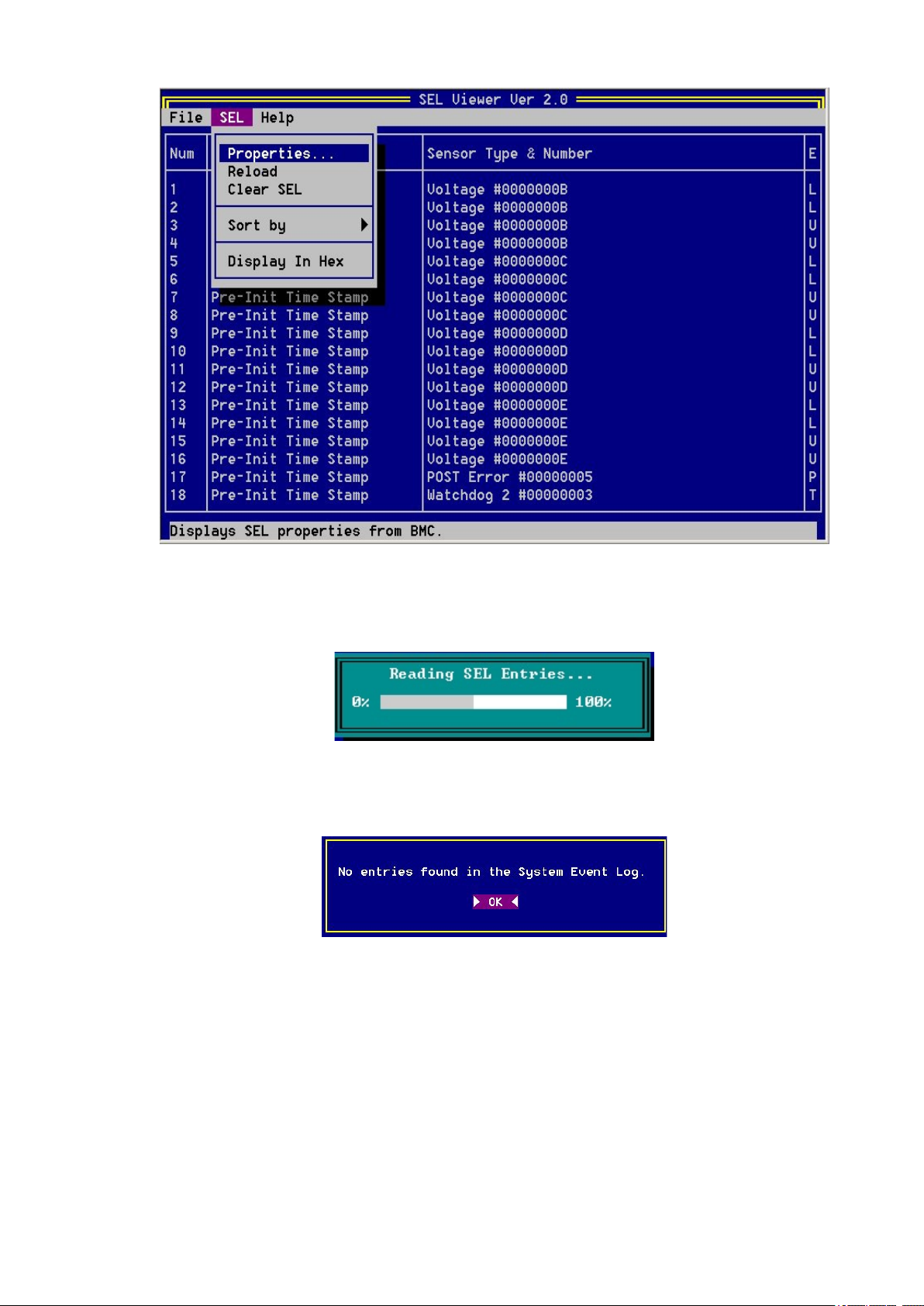
65MAXDATA PLATINUM 90004R Server System
Figure 21. SEL Viewer Utility Main Window
Figure 22. Status Box
Figure 23. Message for Empty Event Log
Page 66
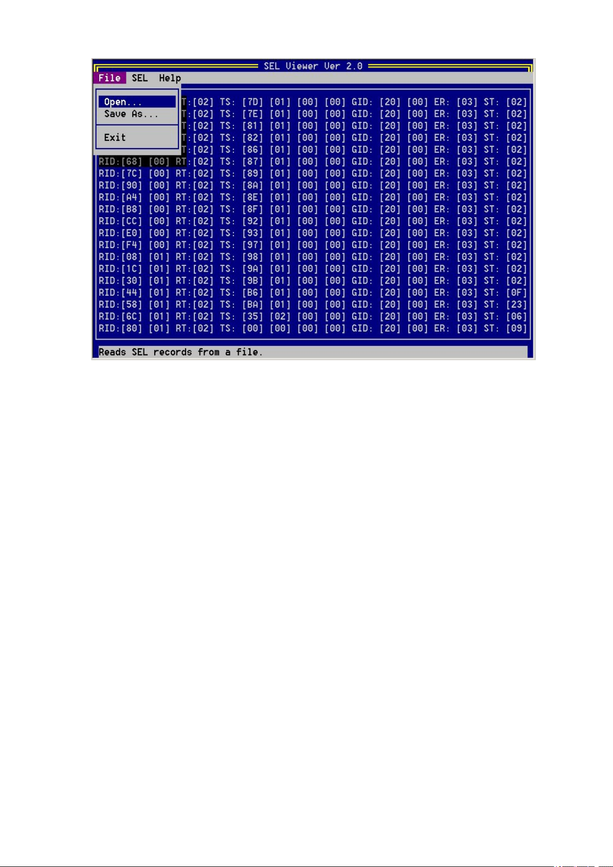
66 Configuration Software and Utilities
67MAXDATA PLATINUM 90004R Server System
Figure 24. SEL Records Displayed in Hex Format
Pull-Down Menu – File
The File pull-down menu includes options for opening and saving system event records from, and to
data les, respectively. These options are further described in the sections below.
File Menu Item – Open
This option allows you to open an existing SEL data le for viewing. Selecting this option prompts you
to specify a lename having the “.sel” le name extension. The SEL le is displayed on the original
mode that it was saved on either raw hexadecimal or interpreted format.
The Open dialog box provides you with the ability to browse drives and directories for existing les,
as shown in Figure 25. If the selected le cannot be opened, this program displays error messages
accordingly.
Page 67
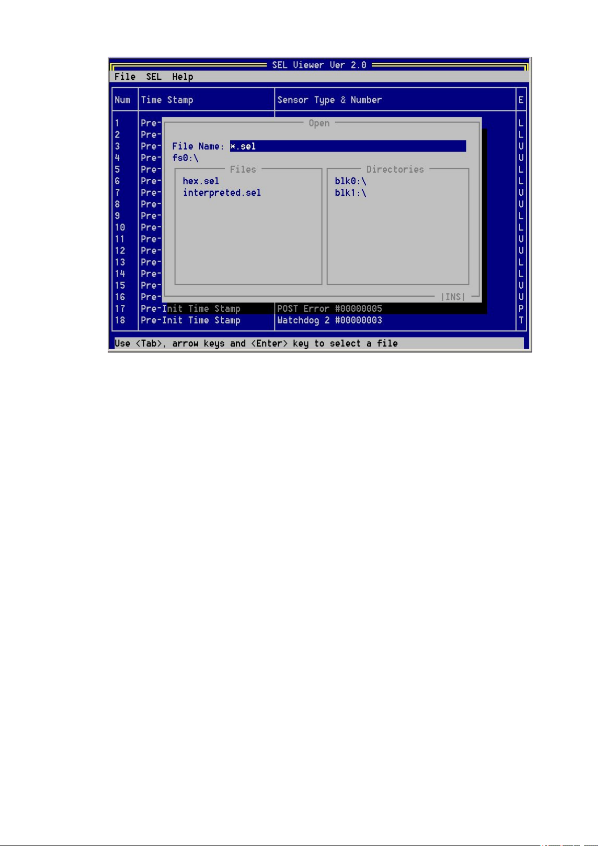
67MAXDATA PLATINUM 90004R Server System
Figure 25. File Open Window
File Menu Item – Save As
This option allows you to save the SEL data to a le, with the “.sel” le name extension, either in
interpreted text format or in raw hex format, depending on the mode in which records are currently
displayed.
The interpreted text format les contain the SEL properties in the rst lines followed by a blank line
and the column headings. The SEL le format is specied as an ASCII-readable le, with each eld
delimited to a TAB and each system event ending with a carriage return/line feed. The columns might
not line up to allow for this le to be opened by programs such as Microsoft® Excel.
The raw hex format les also contain the SEL properties in the rst lines followed by a blank line.
These les contain the SEL records in raw hexadecimal format, as read from the server. This SEL
le format is specied as an ASCII-readable le, with each system event ending with a carriage
return/line feed.
This option also provides you with the ability to select drives and directories by browsing, as shown in
Figure 25. If the SEL data cannot be saved or the le cannot be created or overwritten, the program
displays error messages accordingly.
File Menu Item – Exit
This option allows you to exit the utility.
Pull-Down Menu – SEL
The SEL pull-down menu includes options for reloading SEL entries from the server, clearing the SEL
entries, viewing SEL properties, and sorting the entries by different column elds. These options are
further described in the sections below.
Page 68
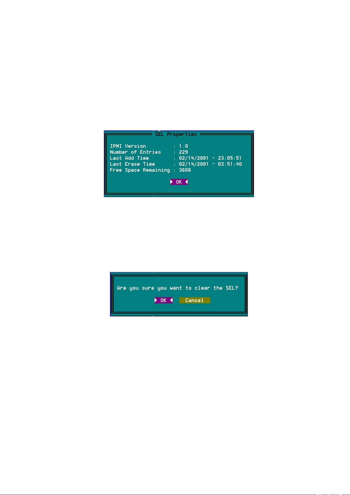
68 Configuration Software and Utilities
69MAXDATA PLATINUM 90004R Server System
SEL Menu Item – Reload
This option allows you to reload the SEL entries from the server. This operation is similar to the one
performed when the SEL Viewer is rst invoked. The records are displayed either in the hex format
or in the interpreted format, depending on the set display mode. The status box shown in Figure 22
is displayed to indicate that the SEL Viewer is loading SEL records from the server, and the message
shown in Figure 23 is displayed if the SEL is empty.
SEL Menu Item – Properties
This option allows you to view the SEL properties as shown in Figure 26. The text “Warning: System
Event Log is FULL” is displayed if the SEL is full; otherwise, the text is omitted. The “Number of
Entries” and “Free Space Remaining” are displayed as decimal values.
Figure 26. SEL Properties
SEL Menu Item – Clear SEL
This option clears the SEL entries from the non-volatile storage area of the server as well as the
entries from the main window table. A dialog message prompts you for the conrmation of clearing
the SEL, as shown in Figure 27.
Figure 27. Confirmation for Clearing SEL
SEL Menu Item – Display In Hex / Display In Text
This option allows you to toggle between the raw hexadecimal mode display and the interpreted
mode display. In hex mode display, all the SEL records are displayed in raw hex format as shown in
Figure 24. In interpreted mode display, all the SEL records are decoded and displayed in text format,
as shown in Figure 21. The menu item name toggles between “Display in hex” and “Display in text”
to allow changing from one display mode to the other. When the display mode is changed, SEL Viewer
automatically loads the SEL entries from the server, and displays it in the new display mode. Display
mode is toggled between text and hex, automatically, when the SEL entries are read from a le,
depending on whether the le contains hex data or text data.
Page 69
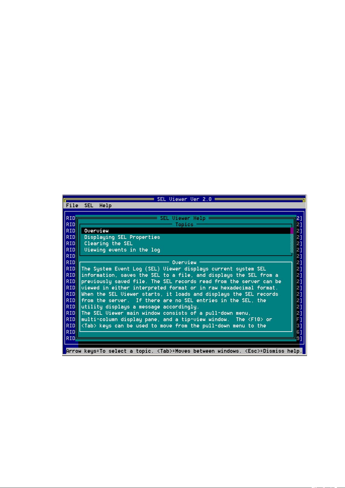
69MAXDATA PLATINUM 90004R Server System
SEL Menu Item – Sort By
This option allows the SEL entries, displayed in the SEL Viewer main window, to be sorted by different
elds. This option, when selected, presents you with a list of elds by which the entries can be sorted.
Upon choosing the appropriate eld, sorting is done by that eld.
Pull-Down Menu – Help
The help menu displays detailed information about the program usage. It also displays the utility
version information and IPMI driver version number.
Help Menu Item – General Help
This option displays a detailed description on how to use the SEL Viewer, as shown in Figure 27. The
help window is divided into two windows. The top window lists all the main topics and the bottom
one displays the description about the topic currently selected. Users can select different topics using
the arrow keys. To move between windows, use <F10> or <Tab> keys. To dismiss the help window,
press <Esc> key.
Help Menu Item – About
This option displays utility version and copyright information about this utility. It also displays the IPMI
driver version that is currently loaded.
Figure 28. Help Window
Page 70

70 Configuration Software and Utilities
71MAXDATA PLATINUM 90004R Server System
Command Line Interface
This utility parses the command line arguments and sets internal ags to control operation. Any invalid
parameters will result in a “usage” message being displayed and the program exiting with an error
code (see Appendix D).
The command line options are listed in Table 18 and are accessed with the forward slash “/” character.
The basic command line format is:
Selview [Options]
Table 18. Command Line Switches
Parameter Description
Selview The name of the utility.
[File Name] Output file name (and path) used for saving SEL entries. This option is used in
conjunction with “/save”.
/clear Clear SEL entries from the non-volatile storage area. This option can not be used
with any other option.
/save Save SEL entries to a file; entries are saved in interpreted text format by default. If
file exists, it is overwritten with the new SEL entries.
This option also requires a file name; that is, the [File Name] option.
/hex SEL entries are saved to a file in hex format instead of interpreted text format. This
option is used in conjunction with “/save”.
/h or /? Displays command line help information.
System Maintenance Utility
The System Maintenance Utility is an EFI-based program that provides the ability to view or modify
server management rmware conguration settings. The rmware conguration is maintained by the
BMC. The executable program for the SMU is named smu.e.
The SMU lets you:
• Congure serial/modem channels for remote server management over a modem or direct
serial connection.
• Congure LAN channels for remote server management over the network.
• Congure users and associated passwords that are allowed access to the channels. Users and
channels can also be assigned privilege levels to further dene who can access them.
• Congure platform events to dene what actions should take place when specic events
occur.
• Congure serial over LAN and terminal mode capabilities.
Page 71

71MAXDATA PLATINUM 90004R Server System
Remote SMU Keyboard Support
The remote SMU application requires a pointing device for operation; it does not support accelerator
keys. Other keys work as dened in Table 19.
Table 19. Keyboard Support for Remote SMU Client
KEY FUNCTION
<Enter> Pressing the <Enter> key when focus is on a button causes the action associated
with that button to occur.
<Tab> Moves focus to the next control in the tab order in the primary information pane.
<Shift><Tab> Moves focus to the previous control in the tab order.
Local SMU Keyboard Support
The local SMU application provides keyboard support as follows:
• <Tab> key – Moves input focus to the next selectable control in the currently active pane.
• <UP arrow> key – Moves input focus to the previous selectable control in the currently
active pane.
• <DOWN arrow> key – Same as the <Tab> key.
• <RIGHT arrow> key – Same as the <Tab> key.
• <LEFT arrow> key – Same as the <UP arrow> key.
• <Enter> key – If an edit box has focus, pressing the <Enter> key has the same effect as
pressing the <Tab> key. When the focus is on a task menu item, a task button, a radio button,
or a checkbox, pressing <Enter> selects the control as if the control were clicked with the left
button on a mouse. If focus is on a single-select control (combo box), pressing <Enter> has no
effect.
• <F5> key – If there is a horizontal scroll bar in the active pane, pressing <F5> scrolls the
display left.
• <F6> key – If there is a horizontal scroll bar in the active pane, pressing <F6> scrolls the
display right.
• <F7> key – If there is a vertical scroll bar in the active pane, pressing <F7> scrolls the
display up.
• <F8> key – If there is a vertical scroll bar in the active pane, pressing <F8> scrolls the
display down.
• <F10> key – Toggles the focus between the task pane and the primary information pane.
• <ESC> key – Causes exit dialog to appear; provides another way to exit the SMU.
The following also hold true when using the above keys while running the local SMU application:
• For single-select controls (combo boxes), the <UP arrow> and <DOWN arrow> keys can be
used to traverse the items in the list. To move to a different control, the <TAB>, <LEFT arrow>,
or <RIGHT arrow> key must be used.
• For a set of grouped radio buttons (only one can be chosen), the <UP arrow>, <DOWN arrow>,
<LEFT arrow>, and <RIGHT arrow> keys can be used to move between buttons in the group.
To move to a different control, the <Tab> key must be used.
• For edit box controls, the <LEFT arrow> and <RIGHT arrow> keys can be used to move the
cursor within the edit box. To move to a different control, the <Tab>, <Enter>, <UP arrow>, or
<DOWN arrow> key must be used.
Page 72
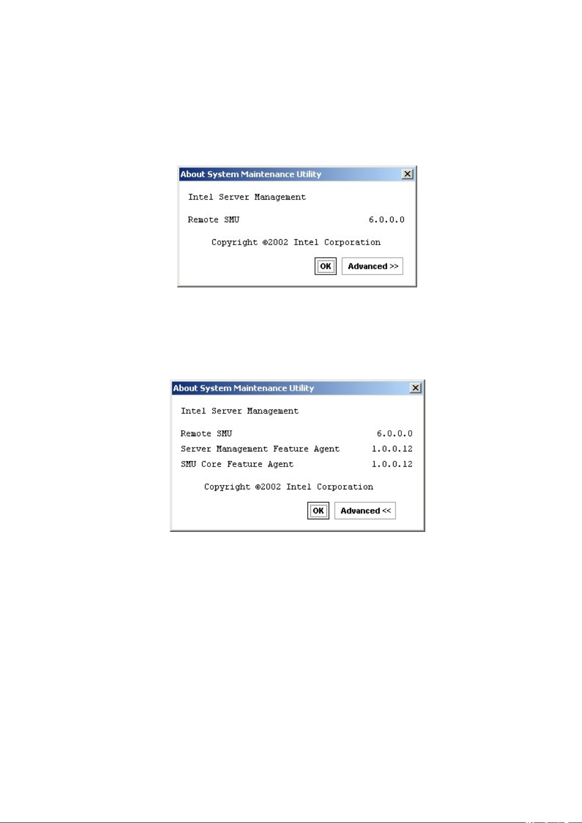
72 Configuration Software and Utilities
73MAXDATA PLATINUM 90004R Server System
About Box Information
The local and remote SMU containers both contain an “About” item in the task pane when the task
list is displayed. When About is clicked, a dialog box is displayed showing information about the SMU
application version. The information displayed consists of a set of four numbers, dened as follows: a
major feature release number; a minor platform or maintenance release number; a variant, used for
things like different operating systems or languages; and a build number. An example of the About
box display is shown in Figure 29.
Figure 29. SMU Application About Box (Application version information)
The About box also contains an Advanced button that can be used to show version information for
components related to the SMU application. An example of this dialog box is shown in Figure 30.
Figure 30. SMU Application About Box (Related component information)
Page 73
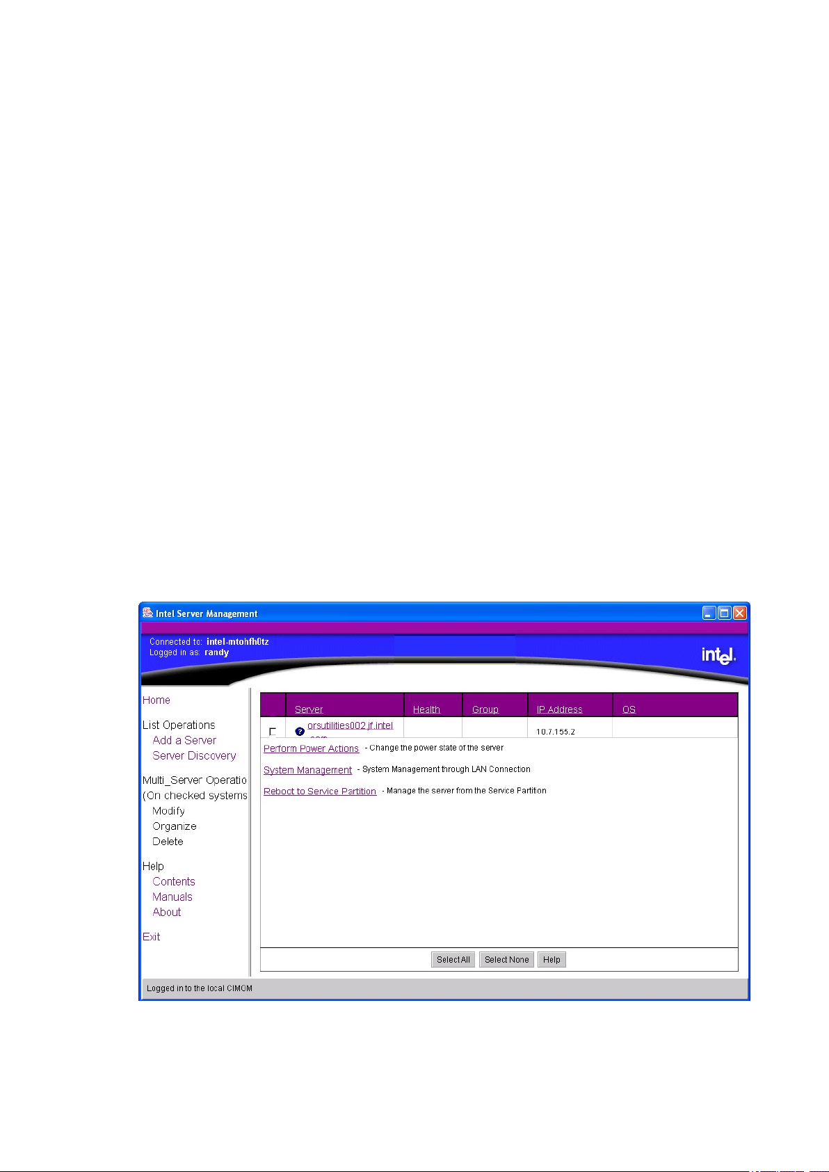
73MAXDATA PLATINUM 90004R Server System
SMU Application Startup and Shutdown
This section describes the following items:
• Installation of SMU software.
• Discovery of servers that support the SMU.
• The steps that occur when the local and remote SMU applications are started, along with
describing any user input necessary in each case.
• Determination of a connection path for a remote SMU session.
• How to shut down the local and remote SMU applications.
• Error conditions and handling during startup and shutdown.
Installation of SMU Software
The installation of the remote SMU application software is part of the ISM installation process. This
results in the SMU les being copied to a directory specied during that installation process.
The installation of the SMU core components occurs as part of the installation process for the service
partition software. The service partition software is installed using the system resource CD supplied
with the server. Note that a system partition is created and installed as part of the procedure to
install the service partition software. It is possible to run the SMU local application from a CD without
installing a service partition.
Discovery of Servers That Support the SMU
Running the remote SMU application requires that the Intel® Server Management software be installed
on the client system. When the ISM software is run, it performs a discovery of all servers that support
tools available within ISM. The discovered servers are displayed in the ISM Console. By clicking on a
server name in the table, a list of tools supported on that server is displayed. The SMU is contained
in the set of tools listed under the heading Reboot to Service Partition.
Figure 31 below shows the ISM Console with the supported tools shown for a server.
Figure 31. ISM Console
Page 74
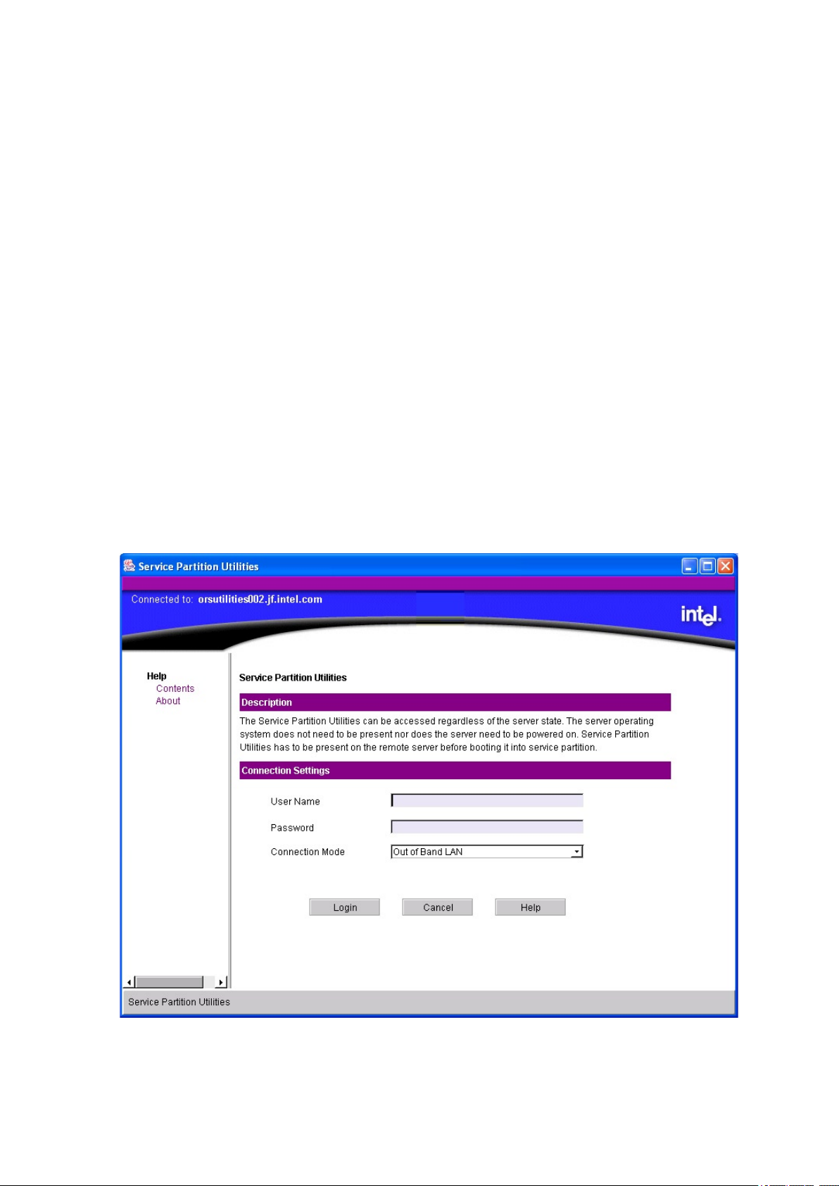
74 Configuration Software and Utilities
75MAXDATA PLATINUM 90004R Server System
Connections Between SMU Applications and Core Components
Remote
The path used to connect to a target server is dened by the ISM software based on information it
has about each server. Currently, the only supported connection path is LAN. After a connection is
established between the remote SMU application and SMU core components running on a server
over some physical medium, the application and the core components set up a socket connection to
communicate over that medium.
Local
In the local case, the local SMU application and the core components exchange XML documents
using a procedural interface. There is no socket connection between the application and the core
components.
Startup of the Remote SMU Application
The sequence of steps that occur when starting up the remote SMU application is listed below. Note
that these steps occur under the control of the ISM software, not the SMU software, so all error
handling during this time is done by the ISM software. For details on this error handling, refer to the
appropriate ISM documentation.
The user clicks the ”Reboot to Service Partition”entry in the list of tools for a server shown in the
ISM Console.
The login screen for the Service Partition Utilities then appears (see Figure 32). At this view, the
username and password for an out-of-band connection should be entered, and the Login button
clicked.
Figure 32. Service Partition Connection View
Page 75
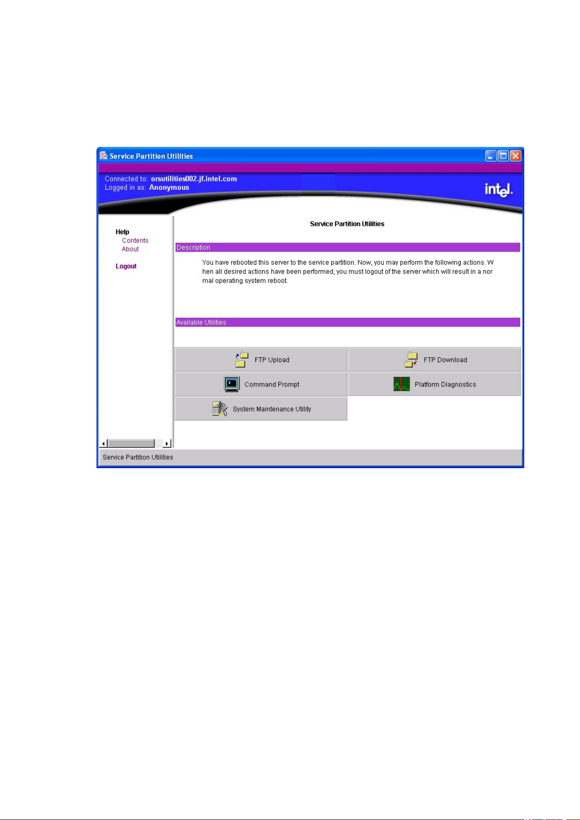
75MAXDATA PLATINUM 90004R Server System
When the server has been successfully rebooted to the service partition software, a screen appears
showing the supported service partition utilities (see Figure 33). Clicking on “System Maintenance
Utility” causes the remote SMU application to be launched. ISM passes connection information to
the SMU so the SMU can talk to the target server. Note that up to this point all errors are handled by
the ISM software, not the SMU, so the appropriate ISM document should be referenced with regard
to the types of errors that can occur and the actions taken if such errors take place.
Figure 33. Service Partition Utilities
Page 76
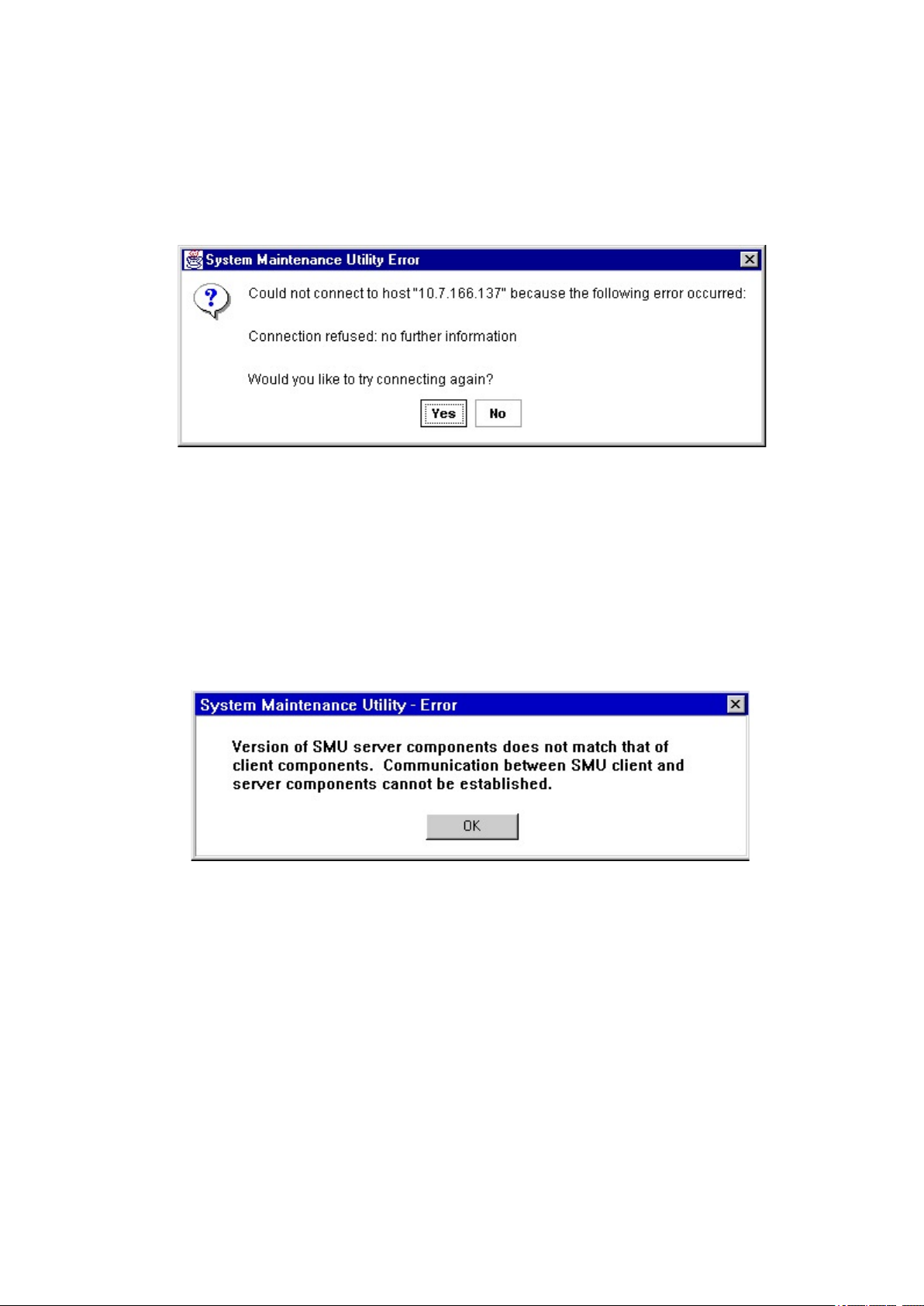
76 Configuration Software and Utilities
77MAXDATA PLATINUM 90004R Server System
The remote SMU application then uses Service Partition Utilities services to execute the server-side
SMU core components. The remote SMU application attempts to establish a socket connection to
the server on an agreed upon socket. The application waits for a predened amount of time (up to
several seconds) before indicating to you that it failed to establish a connection. If a connection is
established, the application sends information to the SMU core components to request a session. If
the connection fails, a dialog box similar to Figure 34 is displayed:
Figure 34. Socket Connection Error Message
When the user clicks “OK”, the remote SMU application will close. The user can attempt to restart
the SMU from the ISM console if desired.
If the session with the SMU core components is established, a version check is made to determine if
the remote SMU application is able to communicate with the SMU core components on the server (i.e.
that the application and core components can understand the messages sent to each other without
problems occurring). If the versions do not match, the message shown in Figure 35 is displayed:
Figure 35. SMU Version Compatibility Error
When “OK” is clicked, the Java SMU application is closed and control is returned to the Service
Partition Utilities application. The SMU cosre components exit on the server and control returns to
an EFI prompt.
Page 77
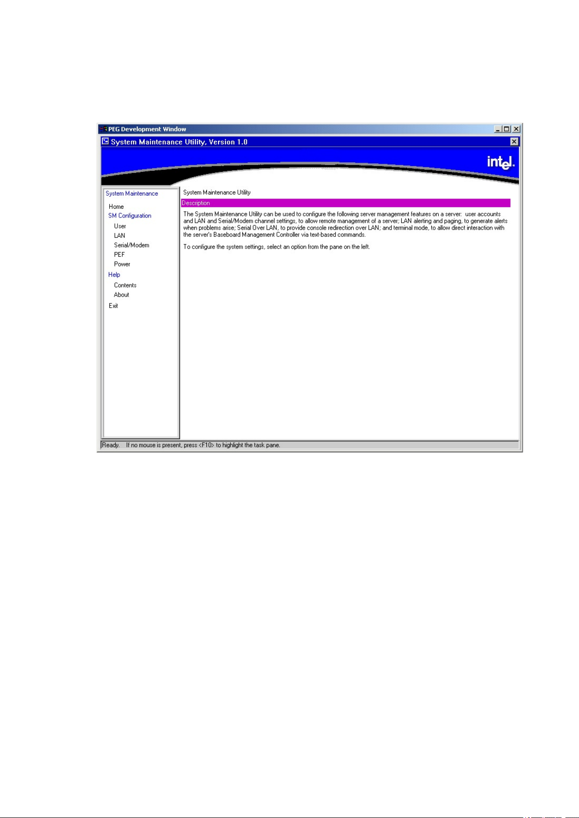
77MAXDATA PLATINUM 90004R Server System
If a session can be set up and the SMU application and core components are the same version, the
core components send task information and the SMU home view that the remote SMU application
displays in the task pane and primary information pane, respectively. The SMU home view directs
you to select a task from the task pane. The SMU home view is shown in Figure 36.
Figure 36. SMU Home View
Startup of the Local SMU Application
The local SMU application can be run either from the system resource CD or, if the SMU software
has been installed locally, from the directory where it was installed on the system partition. Note that
if the SMU software has been installed locally, it can still be run from the CD.
Running from CD
The target server must have a CD drive (EFI currently only supports CDs that contain information in
the “El Torito” format). No network connection is required.
The following sequence of steps must be followed to start the SMU locally (assuming the system
resource CD is being used):
1. Insert the system resource CD into the CD drive on the target server and boot the server to
the EFI shell. The Resource CD menu program starts running automatically and displays a
splash screen followed by its main menu.
2. Use the arrow keys to navigate to the “Utilities” menu item. Press the <Enter> key.
3. Use the down arrow key to highlight the System Maintenance Utility menu item. Press the
<Enter> key. This causes the local SMU application (smu.e) to be started.
Page 78

78 Configuration Software and Utilities
79MAXDATA PLATINUM 90004R Server System
Running from the System Partition
If the SMU has been installed on a system partition, it can be run from there. To do this, follow the
steps below:
1. If an EFI shell prompt is available on the local console and the les on the system partition can
be accessed, skip to step 3.
2. Reset the server and boot to the EFI shell.
3. Locate the lesystem (e.g., fs0:, fs1:) that contains the service partition software and change
directory to \e\service\smu.
4. Run the smu.e application.
Shutdown of the SMU Application
Both the local and remote SMU applications can be exited by clicking on the Exit item in the task
pane or by clicking the Close button in the upper right hand corner of the container. A user can also
use the Close choice in the system menu of either container. An exit operation can be started at any
time (unless the application is blocked waiting for a response from the server). During exit from the
SMU application, the following steps occur:
1. The application sends a message to the SMU core components requesting to end the SMU
session.
2. The SMU core components send a message back to the application asking for user
conrmation of the request to exit. This message is displayed as a dialog box with an “OK”
button and a “Cancel” button.
3. Clicking the “OK” button causes the SMU application to send another message to the server
indicating you want to exit.
4. One last message is sent back to the application from the server before the application shuts
down. In the local case, when the SMU application exits, it exits to the EFI shell so an EFI shell
prompt is displayed. In the remote case, when the remote SMU application is exited, control is
returned to the Service Partition Utilities application (refer to Figure 33).
5. If the “Cancel” button is clicked, you are able to continue the current SMU session.
Server Management Conguration Task
The server management conguration task, if supported on the server the SMU application is
connected to, appears in the task pane. This task allows you to congure server management settings
maintained by the server management controller of the server, usually the Baseboard Management
Controller. To support this task, the target server must support version 1.5 of the Intelligent Platform
Management Interface (IPMI 1.5).
The server management conguration task supports conguration of the following (listed as subtasks
in the task pane):
• Users
• LAN Channel
• Serial/Modem Channel
• Platform Event Filtering (PEF)
• Power Settings
Upon selecting one of the above subtasks in the task pane, a view is displayed containing some or
all of the conguration items that pertain to the selected subtask. The data that is initially displayed
in this view is read from the server management controller of the server. You can then update the
settings and save them back to the server.
Page 79
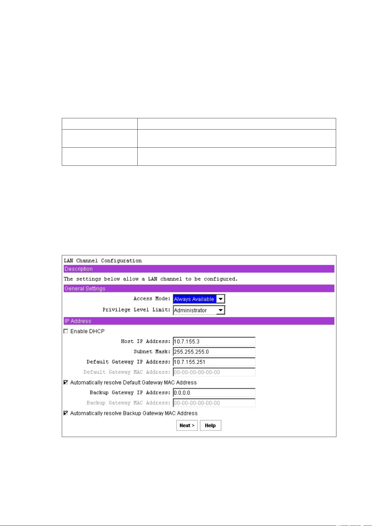
79MAXDATA PLATINUM 90004R Server System
Note that subtasks can be made up of one or more views, depending on the server management
conguration settings enabled by you as the views are displayed. Most views contain common buttons
to perform specic operations. Buttons that are common to all views regardless of the task (Back,
Next, Cancel) are described in the Remote SMU Keyboard Support and Local SMU Keyboard Support
sections. Buttons that are specic to the server management conguration task are described in Table
20. All buttons appear at the bottom of the view.
Note that all views shown in this chapter are what would be shown in the primary information pane
of either the local or remote application; the entire container is not shown in these views.
Table 20. Common Buttons in SM Conguration Views
Button Description
Save Causes the current values of the settings in the current subtask to be
stored in non-volatile memory on the server.
Edit Causes a view to be displayed that allows a user to change settings
related to a single entry in a table.
LAN Channel Conguration Subtask
The LAN channel conguration subtask allows a user to modify settings related to the LAN
channel.
LAN Channel Conguration Initial View
The initial view for conguring the LAN channel is shown in Figure 37. The conguration settings are
described below.
Figure 37. LAN Channel Configuration
Page 80

80 Configuration Software and Utilities
81MAXDATA PLATINUM 90004R Server System
Access Mode
This option is used to congure the access mode for the LAN channel. The available options are
described below.
Always Available
The channel is dedicated to communication with the BMC and is available during all system states
(powered-down, powered-up, pre-boot, sleep, run-time, etc.).
Disabled
The channel is disabled from being used to communicate with the BMC.
Privilege Level Limit
This setting determines the maximum privilege level at which communication on the channel can take
place. It is a global privilege level that takes precedence over user privilege levels, so that if a channel
privilege level is set at User level, for example, then users can only execute user-level commands,
even if the user privilege level is set higher than User.
The meanings of the different privilege levels are described below:
Callback
Only commands needed to initiate a callback session are allowed. Note that although ISM software
does not currently support callback as a connection mechanism, it is still a valid privilege level because
it denes a set of BMC commands that can be executed by a user.
User
Only “benign” commands are allowed. These are primarily commands that read data structures and
retrieve status. Commands that can be used to alter BMC conguration, write data to the BMC or
other management controllers, or perform system actions such as resets, power on/off, and watchdog
activation are disallowed.
Operator
All BMC commands are allowed, except for conguration commands that can change the behavior
of the out-of-band interfaces. For example, Operator privilege does not allow the capability to disable
individual channels, or change user access privileges.
Administrator
All BMC commands are allowed, including conguration commands. An administrator can even execute
conguration commands that would disable the channel that the Administrator is communicating
over.
Enable DHCP
The Enable Dynamic Host Conguration Protocol (DHCP) setting enables the dynamic host conguration
protocol to allow the server to automatically assign the Host IP address, Default Gateway IP address
and Subnet Mask.
Note that when this option is enabled, the Host IP Address, Subnet Mask, and Default Gateway IP
Address edit boxes are grayed out (disabled). The system must be reset in order for this setting to
take effect.
Host IP Address
The Host IP Address is the logical or Internet address of the host. This IP address is required when
DHCP is disabled. The IP address is entered as a dotted notation, e.g., 192.168.0.2.
Page 81

81MAXDATA PLATINUM 90004R Server System
Subnet Mask
The Subnet Mask is the host’s subnet mask. The server uses this to decide if alert destinations are
in the local subnet or in another subnet relative to the client console. The Subnet Mask is required
when DHCP is disabled. The Subnet Mask is entered as a dotted notation, e.g., 255.255.0.0.
Default Gateway IP Address
The Default Gateway IP address is the IP address of the router used when the BMC sends a message
or an alert to a system on a different subnet than the BMC is on. It is required when DHCP is disabled.
The IP address is entered as a dotted notation, e.g., 192.168.0.2.
Default Gateway MAC Address
This edit box allows a user to enter the MAC address of the default gateway router. The MAC address
is entered as a series of six pairs of hex digits separated by dashes, e.g. 00-01-62-d0-3e-66. Alphabetic
hex digits (a-f) can be entered in uppercase or lowercase. This edit box is grayed out by default and
is only activated if the checkbox to allow gateway MAC addresses to be resolved automatically is not
checked. If the edit box is cleared (no address is supplied), a message is displayed asking that a valid
address be entered. This edit box is also disabled if DHCP is enabled.
Automatically Resolve Default Gateway MAC Address
This checkbox allows you to specify whether the BMC should attempt to resolve the MAC address
of the default gateway router automatically. If unchecked, the assumption is that you are entering
the MAC address in the edit box provided. If the checkbox is checked and the BMC cannot resolve
the MAC address, you will be informed of this and asked to provide the MAC address in the edit box
provided in this view. The view is redisplayed with this checkbox unchecked. Any user data previously
entered remains in the view.
This checkbox is checked by default unless the MAC address edit box appears to have a valid MAC
address. A MAC address of 00-00-00-00-00-00 is considered invalid, so the checkbox would get
checked when the SMU displays the view in that case. If the checkbox is unchecked, the default
gateway MAC address edit box becomes active (it is grayed out when this checkbox is checked). If
it is still checked when the OK button is clicked, the rmware immediately attempts to resolve the
gateway MAC address. If it cannot be resolved, a message is displayed to you stating that the address
cannot be resolved and that the MAC address should be entered. This checkbox is also disabled if
DHCP is enabled.
Backup Gateway IP Address
This edit box allows a user to enter the IP address of a backup gateway router. The IP address is
entered as a dotted notation, e.g., 192.168.0.2.
Backup Gateway MAC Address
This edit box allows a user to enter the MAC address of the backup gateway router. The MAC address
is entered as a series of six pairs of hex digits separated by dashes, e.g. 00-01-62-d0-3e-66. Hex digits
can be entered in uppercase or lowercase. This edit box is grayed out by default and is only activated
if the checkbox to allow gateway MAC addresses to be resolved automatically is not checked. If the
edit box is cleared (no address is supplied), a message is displayed asking that a valid address be
entered.
Automatically Resolve Backup Gateway MAC Address
This checkbox allows you to specify whether the BMC should attempt to resolve the MAC addresses
of the backup gateway router automatically. If unchecked, the assumption is that you are entering
the MAC address in the edit box provided. If the checkbox is checked and the BMC cannot resolve
the MAC address, you will be informed of this and asked to provide the MAC address in the edit box
provided in this view. The view is redisplayed with this checkbox unchecked. Any user data previously
entered remains in the view.
Page 82

82 Configuration Software and Utilities
83MAXDATA PLATINUM 90004R Server System
This checkbox is checked by default unless the MAC address edit box appears to have a valid MAC
address. A MAC address of 00-00-00-00-00-00 is considered invalid, so the checkbox would get checked
when the SMU displays the view in that case. If the checkbox is unchecked, the default gateway
MAC address edit box becomes active (it is grayed out when this checkbox is checked). If it is still
checked when the OK button is clicked, the rmware immediately attempts to resolve the gateway
MAC address. If it cannot be resolved, a message is displayed to you stating that the address cannot
be resolved and that the MAC address should be entered.
Default LAN Conguration Settings Set by the SMU
The SMU also sets some server management rmware settings that are not exposed to you. The list
of these settings are given below: Note that for these settings to be set by the SMU, you must click
the Save button on the last LAN conguration view.
Gratuitous ARPs may be enabled
This setting allows the BMC to generate gratuitous ARPs, which provides a mechanism for IP devices
to locate the hardware addresses of other devices on the local network. If the server has a valid IP
address and the LAN channel is enabled for messaging (the access mode is not set to Disabled) or
alerting, then gratuitous ARPs are enabled.
Authentication enables are enabled
These bits dene what types of authentication are enabled to authenticate messages sent to the
BMC by users of different privilege levels. The SMU enables authentication of type straight password,
MD2, MD5, and none. (Refer to the IPMI specication for more information on these authentication
types.)
User-level authentication is disabled
The SMU disables user-level authentication so that if a user is attached with a privilege level of User,
no authentication is done on messages sent to or from the BMC. This speeds up the performance
of the session.
LAN Alert Conguration
The LAN Alert Conguration view (see Figure 38) shows all currently congured destination IP
addresses for LAN alerts and their associated settings. If no IP addresses are currently congured
as alert destinations, the Edit and Delete buttons are grayed out.
Page 83
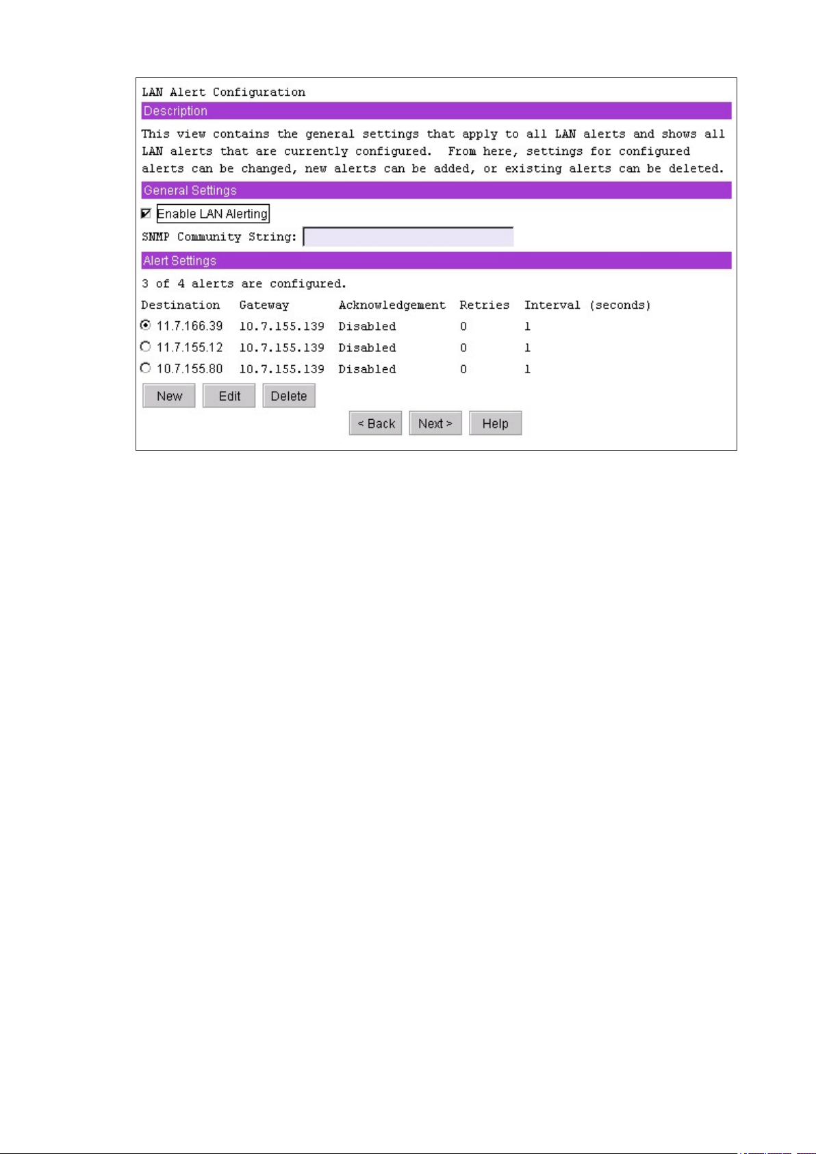
83MAXDATA PLATINUM 90004R Server System
Figure 38. LAN Alerting Configuration
Enable LAN Alerting
This checkbox is used to enable or disable alerts on the LAN channel.
SNMP Community String
This edit box is used to enter string that is entered in the Community String eld for Platform Event
Traps (PETs). This string can optionally be used to hold a vendor-specic string that is used to provide
the network name identity of the system that generated the event. This string is 18 bytes maximum
and it is typically set to “public”. This string cannot be null.
Alert Settings
When one or more IP addresses are congured as alert destinations, this section shows those
addresses along with the following associated conguration settings:
• Gateway IP address for the destination IP address.
• Whether alert acknowledge is enabled for the alerts sent to this destination.
• The number of times the alert will be retried.
• The interval in seconds between retries.
The number of LAN alert destinations is platform specic. For the MAXDATA PLATINUM 9000-4R
Server, the number of LAN alert destinations is 4.
Page 84
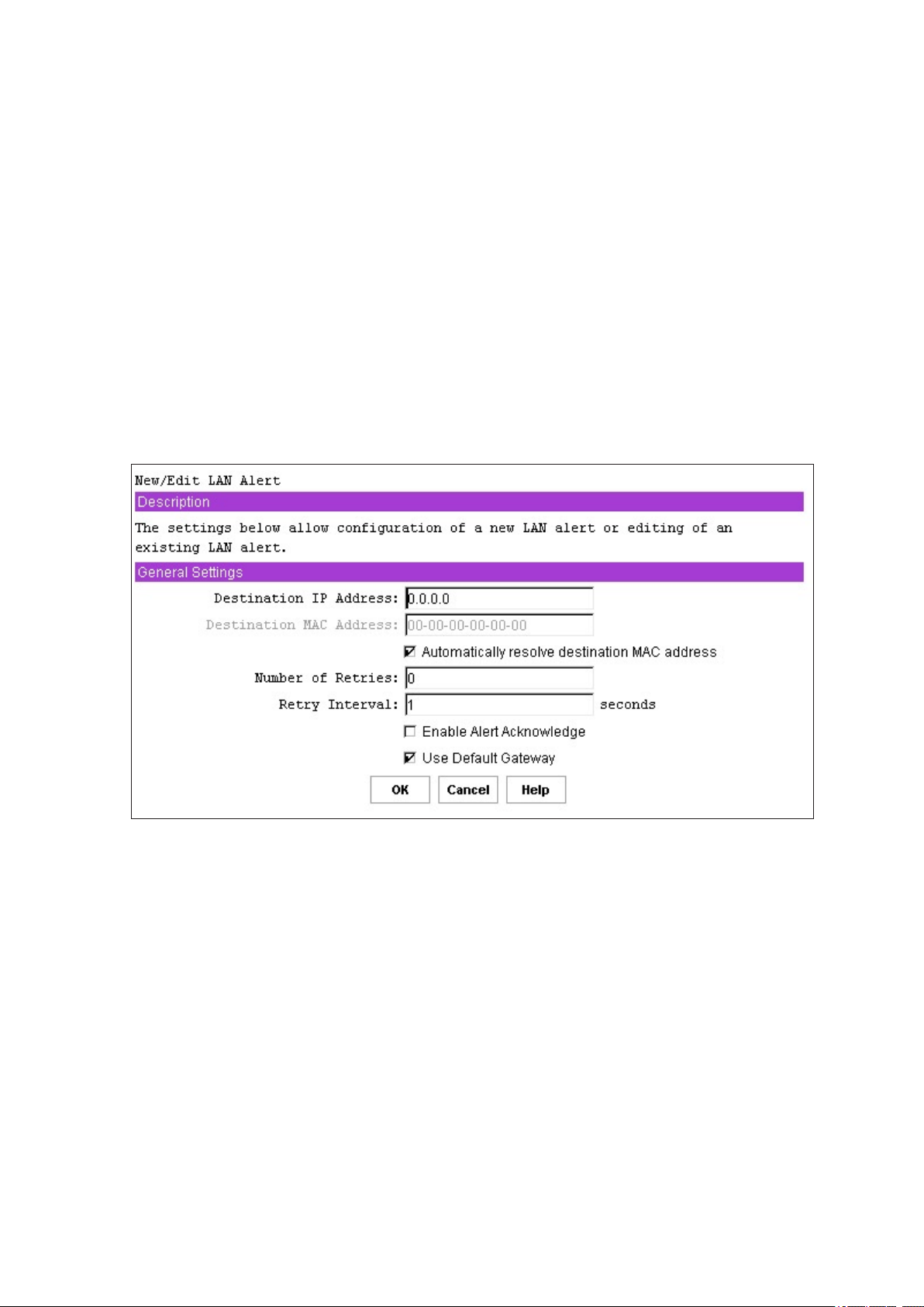
84 Configuration Software and Utilities
85MAXDATA PLATINUM 90004R Server System
New, Edit, and Delete Buttons
If the New button is clicked, a view is displayed to allow conguring of a new LAN destination address;
refer to the following section. If the Edit button is clicked, a view is displayed to allow editing of the
conguration for the currently selected destination IP address (the address whose radio button is
selected in the list). The Delete button is clicked to delete the currently selected destination IP address
(the one whose radio button is selected in the list). Before deleting, you are shown a popup dialog box
to conrm the delete operation. If OK is clicked, the LAN Alerting Conguration view is redisplayed
with the deleted address no longer shown. If no alerts are currently congured, only the New button
is enabled. Note that these buttons only affect the copy of the rmware data internal to the SMU.
Any changes are only written to non-volatile storage in the rmware when the Save button in the last
LAN conguration view is clicked.
New/Edit LAN Alert View
This New/Edit LAN Alert View shown in Figure 39, allows you to congure or change the settings related
to an IP address that is to receive alerts. The view is displayed to congure a new alert destination
or edit an existing one is the same except that when editing an existing alert destination, the current
settings read from the rmware are shown in the view.
Figure 39. New/Edit LAN Alert View
Destination IP Address
This edit box allows a user to enter the IP address to which an alert is to be sent. The IP address
is entered as a dotted notation, e.g., 192.168.0.2. The SMU does not check whether an IP address
entered by you matches one previously entered.
Page 85

85MAXDATA PLATINUM 90004R Server System
Destination MAC Address
If the destination IP address is outside the subnet that the server is on, this edit box is used to enter
the MAC address of the destination machine to which the alert should be sent. The MAC address
should be entered as a series of six pairs of hex digits separated by dashes, e.g. 00-01-62-d0-3e-
66. Alphabetic hex digits (a-f) can be entered in uppercase or lowercase. This edit box is grayed out
by default and is only activated if the checkbox to allow gateway MAC addresses to be resolved
automatically is not checked.
Automatically Resolve Destination MAC Address
This checkbox allows you to specify whether the BMC should attempt to resolve the MAC address
of the destination machine automatically. If unchecked, the assumption is that you are entering the
MAC address in the edit box provided. If the checkbox is checked and the BMC cannot resolve the
MAC address, you are informed of this and are asked to provide the MAC address in the edit box
provided in this view. The view is redisplayed with this checkbox unchecked. Any data previously
entered remains in the view.
This checkbox is checked by default. If it is unchecked, the destination MAC address edit box becomes
active (it is grayed out when this checkbox is checked).
Number of Retries
This edit box allows a user to enter the number of times to retry sending an alert to a given destination.
If set to 0, no retries will be done; the alert is only sent once. If the option is enabled, the alert will
only be retried if a timeout occurs while waiting for the acknowledge. If alert acknowledge is enabled,
then retries are only done if a timeout occurs waiting for the acknowledge. If alert acknowledge is
disabled, the number of retries is the number of times an unacknowledged alert is sent out.
Retry Interval
This edit box is used to set the retry interval, in seconds, when sending an alert or to set the
acknowledge timeout when alert acknowledge is enabled. The recommended default is 3 seconds.
This value is ignored if alert acknowledge is disabled. This setting can have a value from 1 to 255
inclusive.
Enable Alert Acknowledge
This checkbox should be checked if the destination IP address should send an alert acknowledge
when an alert is received. If this checkbox is checked, then an alert is only assumed to have been
successfully sent if an acknowledge is received.
Use Default Gateway
This checkbox should be checked if the IP address entered as the default gateway IP address for the
LAN channel (on the rst LAN conguration view) should be used as the gateway for this destination
IP address. If this checkbox is not checked, the backup gateway IP address is used as the gateway
IP address. If no backup gateway was specied when the LAN channel conguration was done, this
checkbox will not be displayed.
Page 86
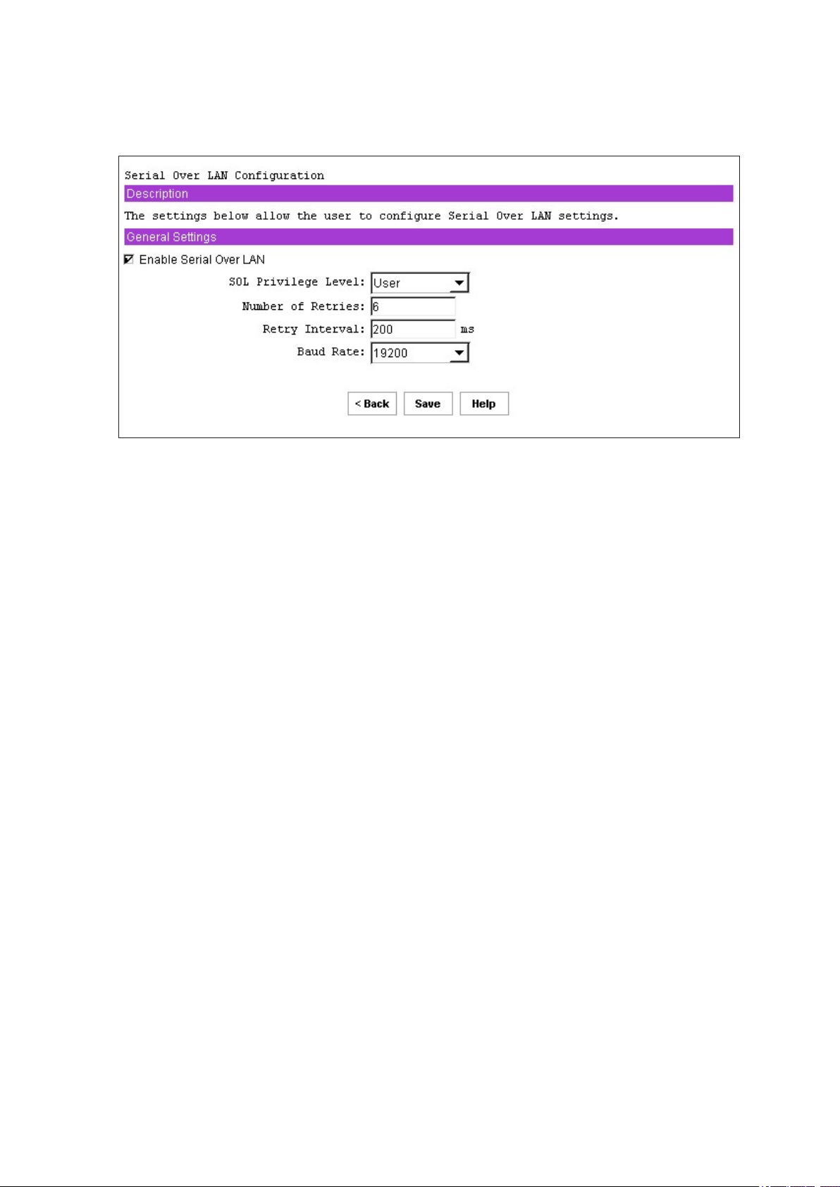
86 Configuration Software and Utilities
87MAXDATA PLATINUM 90004R Server System
Serial Over LAN Conguration View
The serial over LAN view shown in Figure 40 allows conguring the operation of the serial over LAN
capability of the BMC.
Figure 40. Serial Over LAN Configuration View
Enable Serial Over LAN
This checkbox is used to enable or disable the serial over LAN capability.
SOL Privilege Level
This setting is used to select the minimum operating privilege level that is required to be able to
activate SOL. The choices are User, Operator, and Administrator.
Number of Retries
This setting sets the number of times the BMC attempts to resend an SOL message to a remote
console. The number of retries must be in the range 0-7 inclusive.
Retry Interval
This setting sets the number of milliseconds that the BMC waits between retries of SOL messages
to a remote client. The value that can be entered must be in the range from 0-2559 inclusive. Note
however, that the SMU truncates the digit in the ones column from any input number since the
rmware keeps track of this value in 10 millisecond intervals. So, for example, any value entered
between 0-9 shows up as 0.
Baud Rate
This setting sets the baud rate at which serial data is transferred by the BMC when SOL is active. The
choices are Default IPMI, 9600 bps, 19.2 kbps, 38.4 kbps, 57.6 kbps, or 115.2 kpbs. If Default IPMI is
chosen, the baud rate used is the rate currently set for BIOS serial redirection. Note that when SOL
is active, serial communication with the BMC always occurs with 8 data bits, no parity, 1 stop bit,
and RTS/CTS (hardware) ow control.
Default SOL Settings
The SMU by default sets up the SOL conguration such that SOL packets do not have to be
authenticated. This enhances the performance of an SOL session.
Page 87
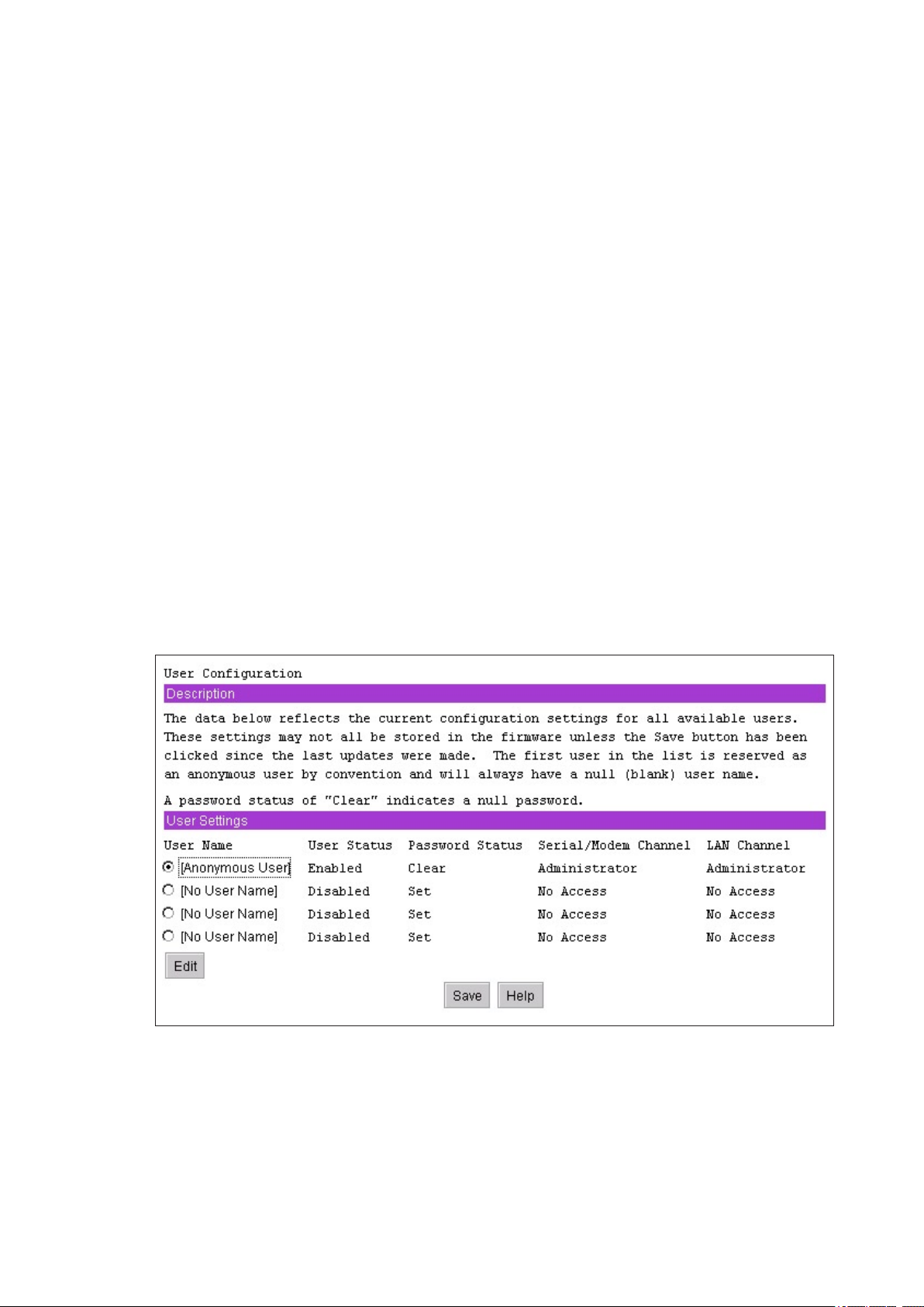
87MAXDATA PLATINUM 90004R Server System
User Conguration Subtask
The User Conguration subtask provides a mechanism for conguring the user access to the LAN
and Serial/Modem channels. Some of the options presented in these views are dependent on how
the channels have been congured; therefore, the channels should be congured before you access
settings (this is not enforced by the software, though).
User Conguration Initial View
After clicking on the User Conguration subtask, the rst view displayed is shown in Figure 41. This
view displays an entry for each possible user that can be congured. This number is platform-specic
and is obtained by the SMU from the rmware. For the MAXDATA PLATINUM 9000-4R Server platform,
the number of users allowed is 4. This view shows whether a particular user is enabled or disabled
for channel access; whether a password is set for the user; and the privilege level the user has for
each of the available channels that supports sessions (users can only access channels that support
sessions). Sessions allow a framework for user authentication and allow multiple IPMI messaging
streams on a single channel.
Note that the rst user is always present and is used to support an anonymous login. The username
for this user is null (blank) and cannot be changed, so the user name shows the text “Anonymous
User.” The password is clear (null) by default but can be changed.
It is possible for multiple user entries to have the same username. One case where this might occur
is if a different password is desired for the same user on different channels. In this case, the privilege
level for the channel that is not to be accessed with the associated password should be set to “No
Access”. Otherwise, the rmware attempts to use the rst entry in the user table that it nds that
allows access to the specied channel and would expect the password associated with that entry to
be the one entered to gain access to the specied channel.
The settings shown in Figure 41 are explained in more detail in the next section.
Figure 41. User Configuration Main View
Page 88
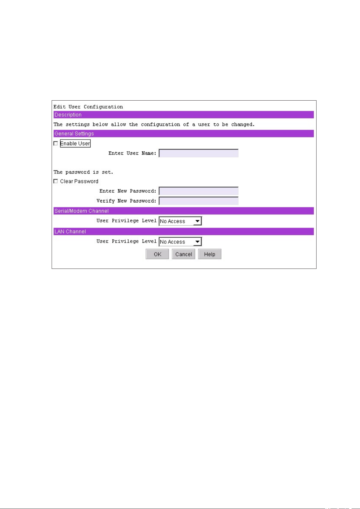
88 Configuration Software and Utilities
89MAXDATA PLATINUM 90004R Server System
Edit User View
Figure 42 shows the view that is displayed when the Edit button is clicked on the User Conguration
main view. Note that any changes made to user settings do not take affect until the next time that
user establishes a session.
If the settings for the anonymous user (the rst user listed) are chosen to edit, the view displayed
is similar to that in Figure 42 except that there is no edit box for the username, since that cannot be
changed.
Figure 42. Edit User Configuration View
Enable User
This checkbox is used to enable a user to attempt to have access to the available channels. Leaving
the checkbox unchecked disables the user, preventing that user from using the channels.
Enter Username
This edit box is used to enter an out-of-band username. For user #1, the anonymous user, the username
cannot be changed (a note on the edit view for user #1 states this also). Usernames can be from 1
to 16 bytes in length, so when entering in ASCII, the password can be from 1 to 16 characters long.
The characters accepted by the SMU for usernames are the ASCII printable characters in the range
0x21 through 0x7e, with the exception of left and right bracket characters (‘[‘ and ‘]’), since those
characters are used for framing packets for terminal mode sessions.
Clear Password
This checkbox is used to clear the password for the user specied. If this checkbox is checked, the
Enter and Verify New Password edit boxes are grayed out.
Page 89

89MAXDATA PLATINUM 90004R Server System
Enter/Verify New Password
These text boxes are provided for entering the password for the user being congured. The Verify
text box is provided so that you can ensure that the password entered in the Enter New Password
eld is correct. As a user enters a password, asterisks are displayed. If a password already exists,
these elds show “********”. This password can be from 1 to 16 bytes in length, so when entering
in ASCII, the password can be from 1 to 16 characters long. The characters accepted by the SMU for
user passwords are the ASCII printable characters in the range 0x21 through 0x7e, with the exception
of left and right bracket characters (‘[‘ and ‘]’), since those characters are used for framing packets
for terminal mode sessions.
Note that if the Clear Password checkbox is checked, these two edit boxes will be disabled.
If a user password is currently set, the SMU user is not required to enter that current password before
changing it. The assumption here is that the SMU user is an administrator that would have rights to
change any passwords.
User Privilege Level for LAN Channels
This combo box allows a user to select the privilege level for LAN channel access for the user being
congured. Note that the global privilege level set for LAN channel access takes precedence over
the user privilege level. So, for example, if the LAN channel is congured for user access only, then
users are limited to user operations regardless of the user privilege level.
Note that one option is available that is not described in that section; this is the “No Access” option,
which disables a user from establishing a session on the channel. This option is available as a user
privilege but not as a channel privilege.
User Privilege Level for Serial/Modem Channel
This combo box allows a user to select the privilege level for serial/modem channel access for the user
being congured. Note that the privilege level set for the serial/modem channel takes precedence over
the user privilege level. So, for example, if the serial/modem channel is congured for user access
only, then users are limited to user operations regardless of the user privilege level.
A description of the possible privilege level choices for serial/modem channel access is given. Note
that one option is available that is not described in that section; this is the “No Access” option, which
disables a user from establishing a session on the channel. This option is available as a user privilege
but not as a channel privilege.
Page 90
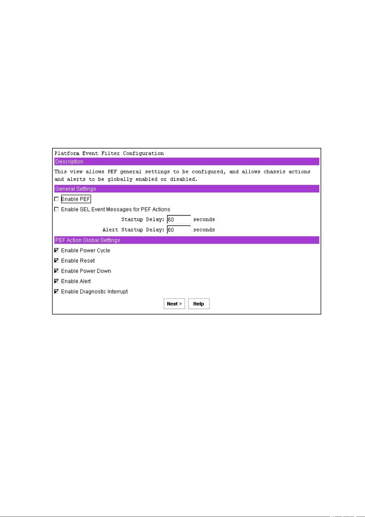
90 Configuration Software and Utilities
91MAXDATA PLATINUM 90004R Server System
Platform Event Filtering (PEF) Subtask
The Platform Event Filtering (PEF) subtask provides a mechanism for conguring the BMC to take
selected actions on event messages that it receives or has internally generated. These actions include
operations such as system power-off and system reset as well as triggering the generation of an
alert.
PEF Conguration Initial View
After clicking on the PEF subtask, the rst view displayed to you is shown in Figure 43.
The BMC maintains an event lter table that is used to select which events trigger an action. Each
time the BMC receives an event message (either externally or internally generated) it compares the
event data against the entries in the event lter table. The BMC scans all entries in the table and
collects a set of actions to be performed as determined by the entries that were matched.
Figure 43. PEF Initial View
Page 91

91MAXDATA PLATINUM 90004R Server System
Enable PEF
This option is used to globally enable or disable platform event ltering.
Enable SEL Event Messages for PEF Actions
When this option is checked, each action triggered by a lter generates an event message for the
action. This allows the occurrence of PEF-triggered events to be logged in the System Event Log (if
event logging is enabled).
PEF Startup Delay
This option is used to congure the time in seconds to delay platform event ltering after a system
power up or reset. The range is 60 to 255. The default is 60 seconds.
Alert Startup Delay
This setting is used to congure the time in seconds to delay sending out alerts after a system power
up or reset. The range is from 0 to 255, where 0 indicates no delay.
PEF Action Global Settings
This set of checkboxes globally enables PEF actions that can occur when an event lter is triggered.
Note that for a lter to trigger a particular chassis action (power cycle, reset, power down, or diagnostic
interrupt), the global setting in this view must be enabled and that chassis action must be selected
for that lter (in the event lter settings view; refer to the next section).
The checkboxes allow enabling or disabling of the following:
Power Cycle
If checked, this checkbox globally enables the Power Cycle action when an event lter is triggered.
Reset
If checked, this checkbox globally enables the system reset action when an event lter is triggered.
Power Down
If checked, this checkbox globally enables the system power down action when an event lter is
triggered.
Diagnostic Interrupt
If checked, this checkbox globally enables a diagnostic (non-maskable) interrupt when an event lter
is triggered.
Alert
If checked, this checkbox globally enables alerts when an event lter is triggered.
Page 92
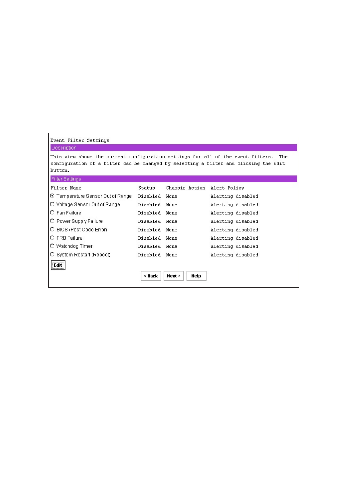
92 Configuration Software and Utilities
93MAXDATA PLATINUM 90004R Server System
Event Filter Settings View
The PEF event lters settings view, shown in Figure 44, displays to users the supported pre-congured
event lters on the platform to which the SMU is communicating, along with settings associated with
the event lters. These associated settings are:
• Whether the lter is enabled or disabled.
• The policy number associated with the lter (only required if alerts are enabled).
• A chassis action that occurs if the lter event occurs.
• Whether alerts are enabled or disabled if the lter event occurs.
The settings associated with a particular lter can be edited. Select the radio button next to a lter and
then clicking the Edit button. Editing the settings is discussed in more detail in the next section.
Figure 44. PEF Event Filter Settings View
Page 93
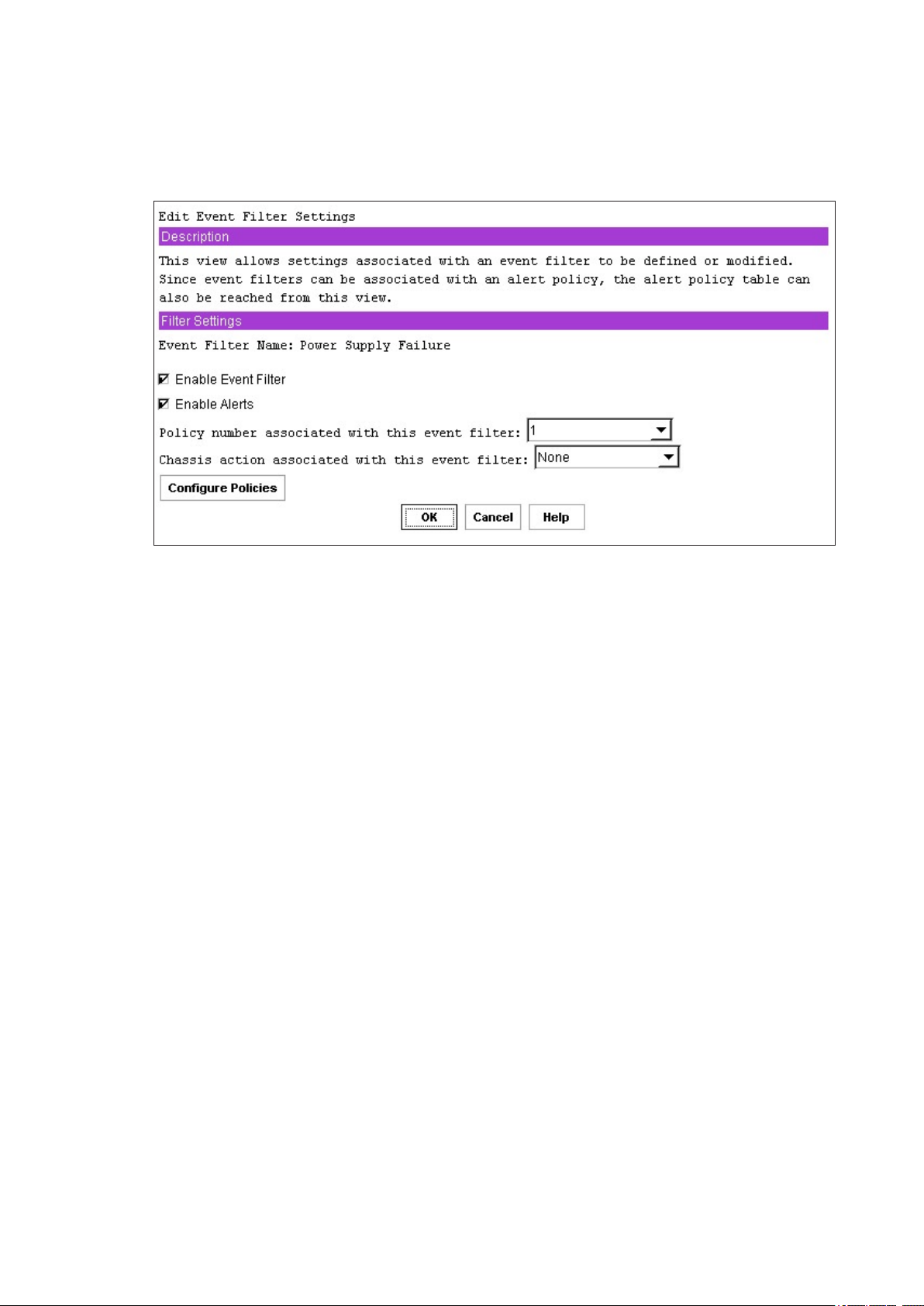
93MAXDATA PLATINUM 90004R Server System
Edit Event Filter View
The view shown in Figure 45 is the view that is displayed after the Edit button is clicked on the Event
Filters Settings view (previous section). The name of the event lter for which settings are being
congured is shown after the description of the view.
Figure 45. Edit Event Filter Settings View
Enable Event Filter
The Enable Event Filter checkbox should be checked to enable the selected lter or unchecked to
disable the lter.
Enable Alerts
This checkbox should be checked to enable an alert to be sent when an event associated with the
selected event lter occurs. If it is not checked, or if the global enable for alerts is not enabled, no
alert is sent.
Policy Number Associated With This Event Filter
This drop-down box allows a user to specify an alert policy number to be associated with the selected
event lter. This setting is only enabled if alerts are enabled (via the Enable Alerts checkbox), meaning
a valid policy number must be chosen if alerts are enabled. The drop-down list shows the valid policy
numbers, which are 1-15 decimal. Policy numbers are assigned to policy table entries by you; refer
to the next section for more details.
Chassis Action Associated With This Event Filter
This drop-down box allows a user to select which chassis action (power down, power cycle, reset,
diagnostic interrupt, none) is associated with the selected event lter. Note that for any chassis action
to occur, it must be globally enabled.
Congure Policies Button
This button provides a shortcut to get to the view that displays the current settings of all entries in
the policy table. From that view, a user can edit a policy table entry or congure an unused entry.
This button is supplied as a way to dene the settings associated with a policy number that can be
selected from the drop-down list described in the previous section.
Page 94

94 Configuration Software and Utilities
95MAXDATA PLATINUM 90004R Server System
OK Button
Clicking the OK button saves all settings currently shown in this view in the internal copy of the data.
The Save button on the last PEF view must be clicked to store these settings into non-volatile storage.
You are returned to the Event Filter Settings view after clicking OK.
Cancel Button
Clicking the Cancel button returns you to the Event Filter Settings view without saving any changes
made to the selected event lter in the internal copy of the data.
Alert Policy Table View
Figure 46 shows all the entries in the alert policy table, regardless of whether any settings are
associated with a particular entry or not. All entries are shown because the entries in the table
are order-dependent, so that when an alert occurs, entries in the table are processed from top to
bottom as the rmware attempts to match table entries with the policy number associated with the
event that caused the alert. By seeing all entries, you are able to ensure that the entries are in the
correct order.
One use of the policy table is to be able to specify multiple destinations for alerts that occur. This can
be done by assigning the same policy number to multiple entries in the table; but specifying different
destinations in the destination eld. If one policy is associated with multiple entries in the policy table,
users can further rene the destinations that receive alerts by using the policy type.
Note that because the rmware goes through the table in order from top to bottom, when an event
occurs, the table is searched in order for entries in which the policy number matches the policy
number associated with the event lter. So, the alert is sent to the destinations in the order in which
they are encountered in the policy table. You should make sure their destinations appear in the table
in the desired order.
The settings shown for each table entry are:
• Alert policy number
• Status indicating whether the table entry is enabled or disabled
• Policy type
• Channel on which the alert corresponding to the table entry would be sent on
• Destination IP address or phone number of the alert
• Alert string associated with the alert
Page 95
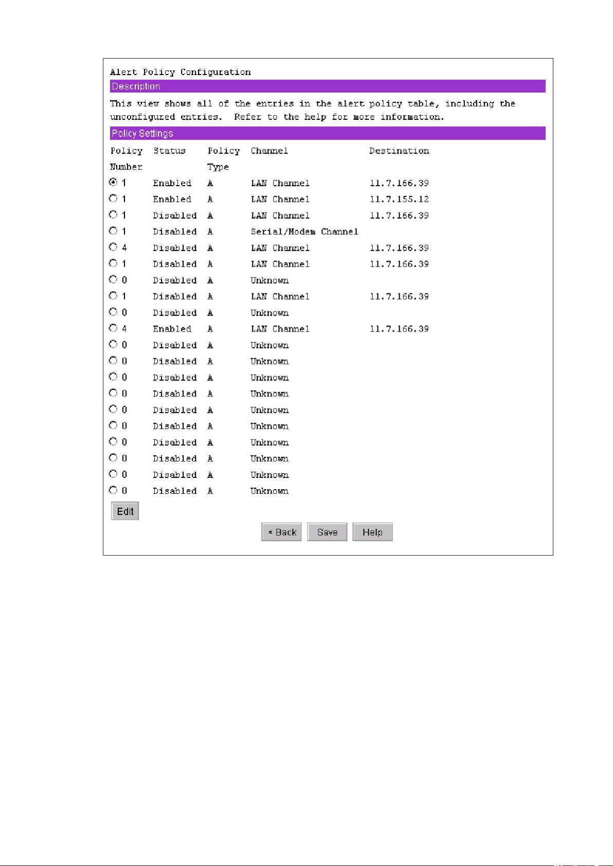
95MAXDATA PLATINUM 90004R Server System
Figure 46. Alert Policy Configuration View
Edit
Selecting an alert policy table entry and then clicking the Edit button displays a view that allows a
user to change the settings for that table entry. The settings that can be changed are described in
more detail in 123.
Page 96
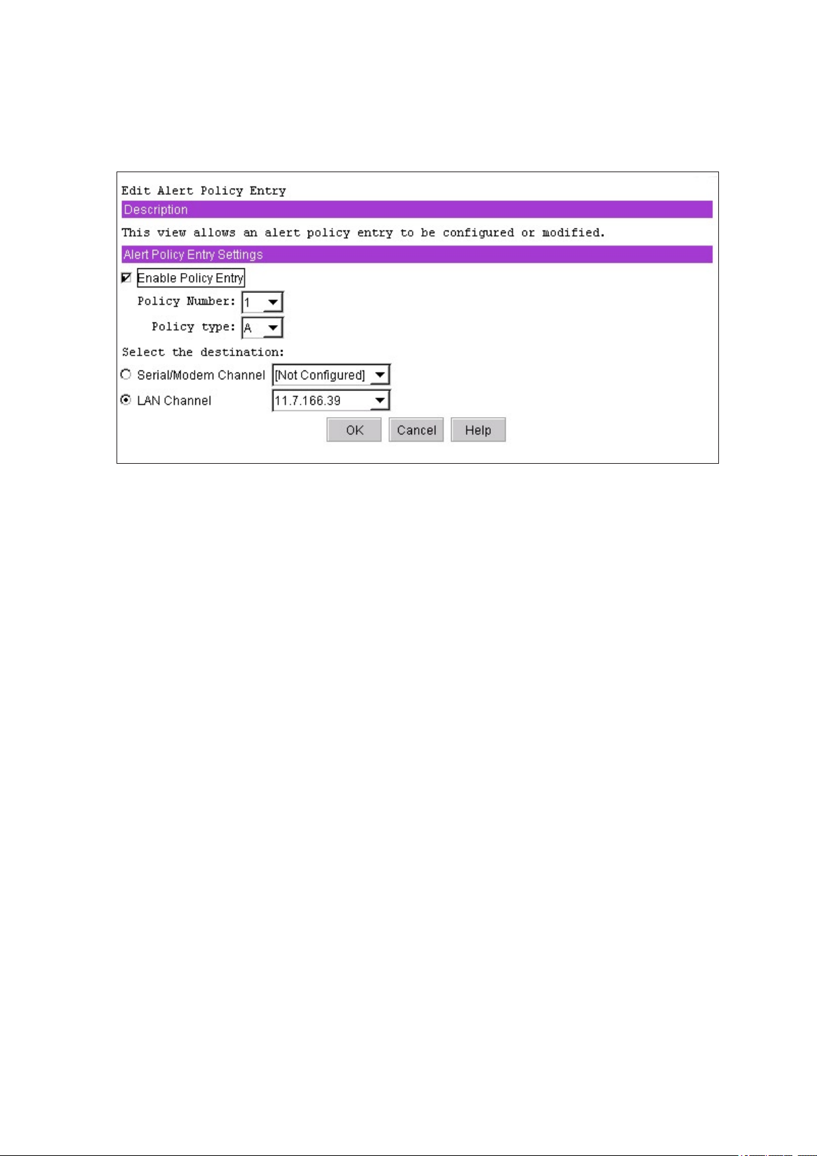
96 Configuration Software and Utilities
97MAXDATA PLATINUM 90004R Server System
Edit Alert Policy Entry View
The view shown in Figure 47 is displayed after clicking the Edit button in the Alert Policy Table view.
The data shown is for whatever entry in the policy table was selected when the Edit button was
clicked.
Figure 47. Edit Alert Policy Entry View
Enable Policy Entry
This checkbox should be checked to enable the selected policy table entry. If the entry is to be disabled,
the checkbox should not be checked. If disabled, the rmware does not look at that table entry when
attempting to match entries to the event that occurred.
Policy Number
This edit box associates a policy number with a policy table entry. If the selected table entry is already
associated with a policy number, that policy number is displayed in the edit box. If no policy number
is currently associated with the selected table entry, 1 is displayed (the rst number in the list of
possible policy numbers. Note that if alerts are associated with event lters, a valid policy number is
required, so it is not possible to select 0 as a policy number, for example (all policy numbers listed in
the drop-down list are valid).
Page 97

97MAXDATA PLATINUM 90004R Server System
Policy Type
This drop-down box displays a list of letters that represent the choices for policies that can be associated
with an alert policy table entry (the assigning of letters to the possible policy choices was done because
the amount of text needed to describe each policy was unwieldy for the user interface). The policy
type determines how or whether the rmware processes multiple entries in the policy table that
have the same policy number (for example, the policy can be used to indicate whether an alert is to
be sent to multiple destinations, to destinations involving the same channel, etc.). The policy choices
are described in context-sensitive help associated with this view, but are also listed below.
• Policy type A = always send an alert to the destination referenced in this policy table entry.
• Policy type B = if the alert to the previous destination was successful, do not send an alert to
the destination referenced in the current policy table entry. Instead, go on to the next entry in
the policy table with the same policy number.
• Policy type C = if the alert to the previous destination was successful, do not send an alert to
the destination referenced in the current policy table entry, and stop processing policy table
entries.
• Policy type D = if the alert to the previous destination was successful, do not send an alert to
the destination referenced in the current policy table entry. Instead, proceed to the next policy
table entry that has the same policy number but has a destination to a different channel.
• Policy type E = if the alert to the previous destination was successful, do not send an alert
to the destination referenced in the current policy table entry. Instead, proceed to the next
policy table entry with the same policy number that has a different destination type (a different
destination type might be a PPP alert instead of a dial page, for example, although this
software does not support PPP alerts).
Select the Destination
This set of radio buttons shows the choice of channel destinations that can be associated with a
policy table entry. Each radio button is associated with a drop-down list of destinations that have been
congured for that channel (e.g. the serial/modem channel radio button is associated with a dropdown box containing dial strings). Only the selection made in the drop-down list associated with the
active radio button (channel) is used if you click the OK button).
OK Button
Clicking the OK button saves all settings currently selected in this view in the internal copy of the data.
The Save button on the last PEF view must be clicked to store the settings into non-volatile storage.
You are returned to the Alert Policy Table view after clicking OK.
Cancel Button
Clicking the Cancel button returns you to the Alert Policy Table view without saving any changes made
to the selected alert policy table entry in the internal copy of the data.
Page 98
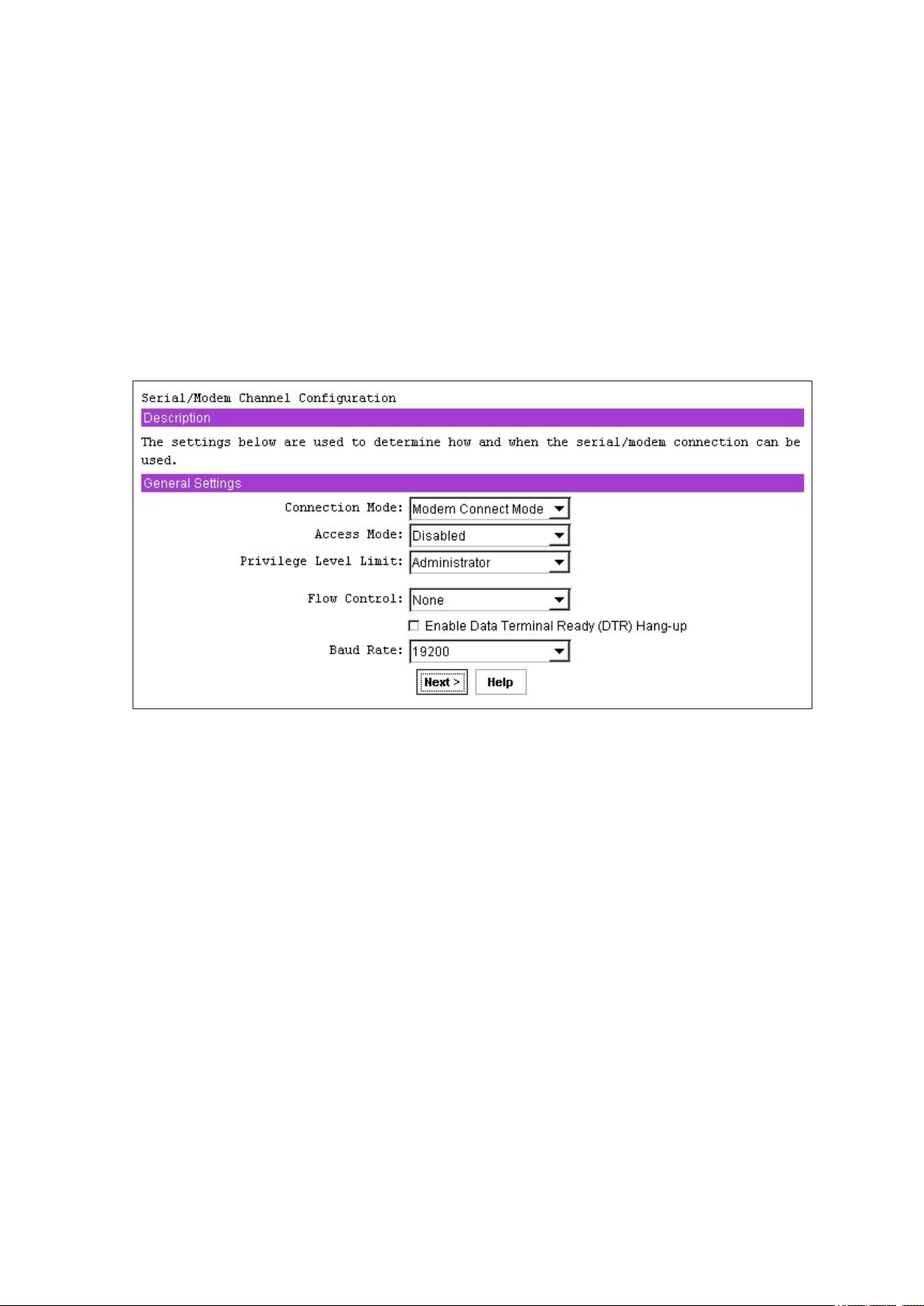
98 Configuration Software and Utilities
99MAXDATA PLATINUM 90004R Server System
Serial/Modem Channel Conguration Subtask
This section describes the views presented to congure serial/modem channel settings.
Serial/Modem Channel Conguration Initial View
The serial/modem channel conguration subtask allows you to modify settings that relate to the
serial/modem channel, set up dial strings to which alerts are sent, and specify the settings related to
sending alerts to those destinations. It also contains a view to congure the settings for the terminal
mode of operation of the serial/modem channel. The initial view for this channel is shown in Figure 48
and each conguration setting is described following the gure. Note that the view that is displayed
when the Next button is clicked depends on which connection mode is chosen: if modem mode is
selected, the next view displayed allows setup of modem parameters; if direct connect is selected,
since there are no conguration parameters to set, the next view displayed is the Destination Dial
Strings view.
Figure 48. Serial/Modem Channel Configuration Initial View
General Settings
This section describes each of the settings that always apply to the serial/modem channel.
Connection Mode
The connection mode determines the protocols used when performing IPMI messaging to the BMC.
After selecting a connection mode, clicking on the “Next” button causes the initial view for the
selected mode to be displayed.
Direct Connect Mode
When Direct Connect Mode is selected, the client console and target server are connected by a null
modem cable from the serial port of one to the serial port of the other.
Modem Mode
When Modem Mode is selected, the client system is able to establish a connection to the target
server using a modem. Each system must have a modem attached, and the user on the client system
must have the dial string needed to call the modem connected to the target server.
Access Mode
This option is used to congure the access mode for the Serial/Modem channel. The choices are:
Page 99

99MAXDATA PLATINUM 90004R Server System
Pre-boot only
The Serial/Modem channel is only available out-of-band while the machine is powered-off and during
POST until the boot process is initiated. This option is primarily used with serial port sharing where
it may be desirable to ensure that the BMC does not take control of the serial port during OS runtime.
The Pre-boot only setting does not affect Serial/Modem alerting. If alerting is enabled and software does
not handle the event, the BMC takes control of the port for the time it takes to deliver the alert.
Always Available
The channel is dedicated to communication with the BMC and is available during all system states
(powered-down, powered-up, pre-boot, sleep, run-time, etc.).
Shared
Same as Always Available, but the BIOS typically leaves the serial port available for software use.
Disabled
The channel is disabled from being used to communicate with the BMC (except for alerting).
Privilege Level Limit
The channel privilege limit sets the maximum privilege level that users can have on this channel and
it restricts users of the channel to a set of BMC commands that can be issued at that privilege level.
For example, if the channel privilege limit is congured with a maximum privilege level of Operator,
even if a user is congured to have Administrator privilege, no commands that require Administrator
privilege can be executed by that user over this channel.
IPMI Messaging Communication Settings
These parameters are the global settings for IPMI messaging, which include Direct Connect and
Modem modes.
Note that IPMI messaging always occurs with 8 bits/character, no parity, and 1 stop bit. The COM
settings that can be congured are:
Flow Control
This option sets how the ow of data is controlled. Available choices are No Flow Control, CTS/RTS
(hardware handshake), and XON/XOFF.
Baud Rate
This option sets the maximum rate in bits per second at which the data can be transmitted through
the serial port. Available baud rates are 9600, 19200, 38400, 57600, and 115200 kbps. Note that
support for baud rates higher than 19200 is optional and SMU only displays the ones that the BMC
supports.
Enable Data Terminal Ready (DTR) Hang-up
When DTR Hang-up is enabled, hang-up of a modem connection is based on when the DTR signal
becomes inactive. Note that when this is enabled, the modem settings Modem Hang-up and Escape
Sequences are not used.
Default Serial/Modem Conguration Settings Set By the SMU
The SMU sets some serial/modem conguration settings that are not exposed to the user. The list
of these settings is given below. Note that for these settings to be set by the SMU, a user must click
the Save button on the last serial/modem conguration view.
Authentication type enables are enabled. These bits dene what types of authentication are enabled
to authenticate messages sent to the BMC by users of different privilege levels. The SMU enables
Page 100
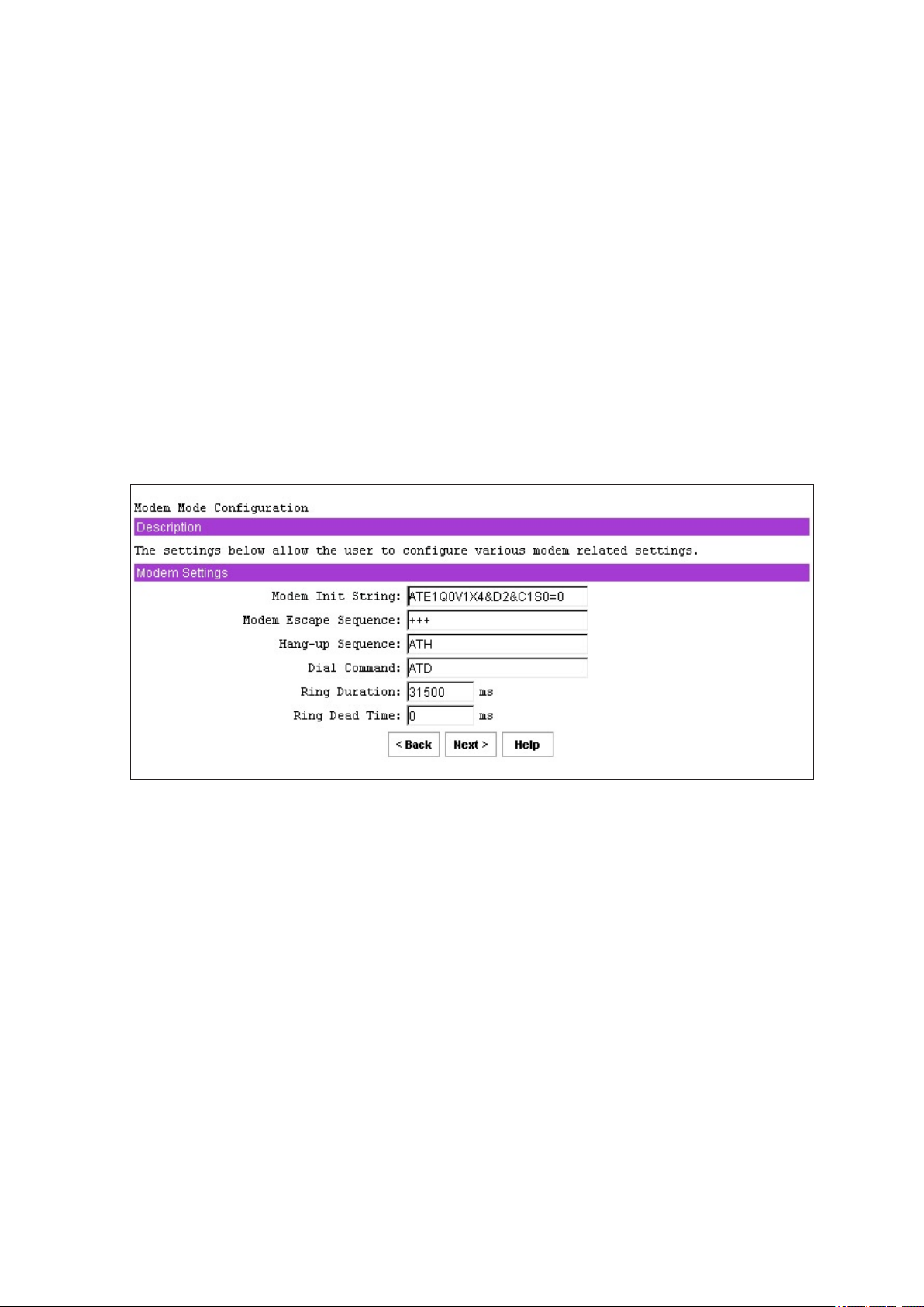
100 Configuration Software and Utilities
101MAXDATA PLATINUM 90004R Server System
authentication of type straight password, MD2, MD5, and none. (Refer to the IPMI specication for
more information on these authentication types.)
Basic mode is enabled, allowing basic serial communications to take place over the serial/modem
channel.
Session inactivity timeout is set to one minute.
Session termination bits are enabled to enable ending of a serial/modem session if an inactivity
timeout occurs or if DCD is lost.
Flow control and baud rate are set for IPMI messaging (ow control is set to hardware ow control;
the baud rate is set to 19.2 kbps).
The multiplexor that determines who controls the serial connector has various default settings enabled
and disabled.
Modem Mode Conguration View
If Modem Mode is chosen in the serial/modem channel conguration initial view, then when the Next
button is clicked, the view shown in Figure 49 is displayed. This mode is for applications that connect
to the server via an external modem.
Figure 49. Modem Settings
Modem Init String
This setting is an ASCII string used to initialize the modem. This string is typically set to
“ATE1Q0V1X4&D2&C1S0=0” and is 64 bytes maximum, including a termination character. The BMC
automatically follows this string with an <Enter> character or carriage return.
Modem Escape Sequence
This setting is an ASCII string representing the Escape string to be sent to the modem before sending
a command string. This string is ve-bytes maximum in length and it is typically set to “+++”. Note
that if this parameter is left empty, the default “+++” sequence is used by the BMC. The modem
escape sequence is not sent to the modem if DTR Hang-up is enabled;
Hang-up Sequence
This setting is an ASCII string that is sent to the modem to terminate the session. The BMC automatically
follows this string with an <Enter> character when sending it to the modem. This string is 8 bytes max
and it is typically set to “ATH”. Note that if this parameter is left empty, the default “ATH” sequence
is used by the BMC. The hang-up sequence is not sent to the modem if DTR Hang-up is enabled;
 Loading...