

Page 1

MAXDATA PLATINUM Server Board
User Manual
Page 2

Page 3

3
Video
ACPI
®
Server Management
Tools and Supplies Needed
3
23
Temporarily Changing the Boot Device Priority
The Adaptec SCSI Select Utility
When to Run the Adaptec SCSI Select Utility
Page 4

4
29
30
30
31
31
31
31
Working with the SSU Interface
32
32
33
33
33
33
34
Viewing the System Event Log
34
Viewing FRU Information
35
Viewing Sensor Data Records
35
36
36
383943
44
45
®
Server Management
46
®
Server Management
46
47
47
48
48
After the System Has Been Running Correctly
48
48
49
Verifying Proper Operation of Key System Lights
49
49
49
Page 5

Technical Reference
Page 6

Figures
3.
J5A2 Jumper Block for DSR Signal
4.
Jumper Locations
Tables
3.
4.
Adaptec Main Menu
Page 7

Table 1. Server Board Features
®
Xeon™ processors in an INT3/FCPGA Socket
®
chipset E7501:
Video Memory
Two PCI riser slots capable of supporting either of the following configurations:
(LP) 64-bit PCI riser slot
PCI riser slots
Two external USB ports, internal connector providing two additional USB
Two NIC ports (RJ-45)
Page 8
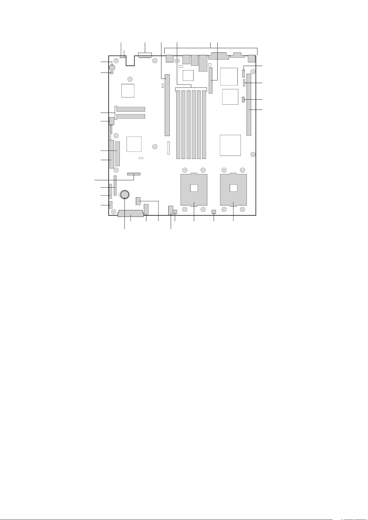
A.
Auxiliary signal connector
Q.
C.
S.
G.
V.
ATX front panel connector
W.
J.
Y.
ATA/IDE connector
the riser card (SCSI only)
Z.
ATA-100 connectors (ATA version only)
CC.
O.
Page 9
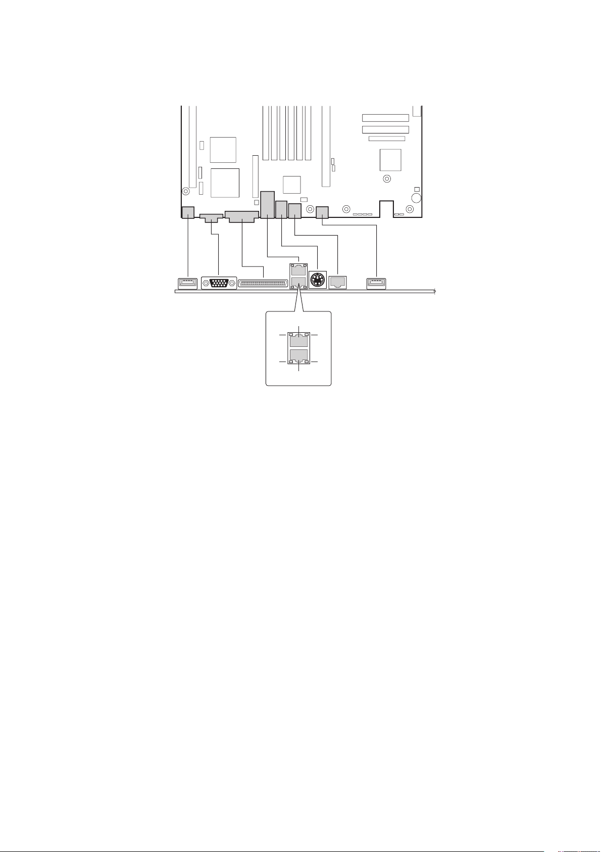
A.
Video connector
C.
G.
J.
Page 10

The MAXDATA PLATINUM Server Board accommodates one or two Intel
®
Xeon™ proces-
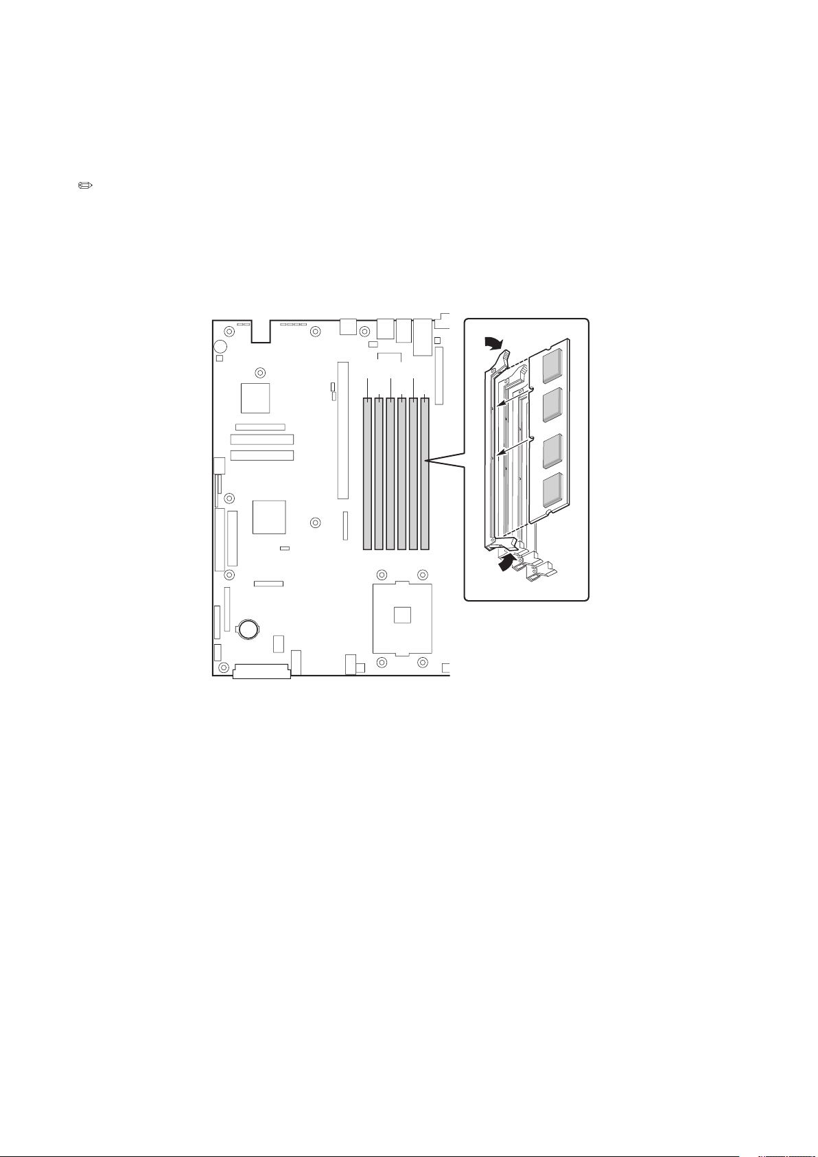
The system board has six 168-pin DIMM slots each supporting 72-bit ECC registered DDR
The controller automatically detects, sizes, and initializes the memory array, depending on
the type, size, and speed of the installed DIMMs, and reports memory size and allocation
to the server via configuration registers.
The server board has two PCI riser slots. Riser slot B provides the following features:
Video
The MAXDATA PLATINUM Server Board uses an ATI RAGE XL PCI graphics accelerator
with 8 MB of video SDRAM. The embedded SVGA video subsystem supports:
The server board supports disabling of the onboard video through the BIOS setup menu or
when a plug in video card is installed in any of the PCI slots.
The SCSI
version of the server board includes an embedded Adaptec AIC-7902W controller
The SCSI bus is terminated on the server board with active terminators that cannot be
terminated through a jumper or resistor pack on the device itself.
Page 11

Controller
To ensure EMC product regulation compliance, the system must be used with a shielded
cable.
The server board uses the Intel
®
Fast Ethernet Controller, 82546EB, and supports two
The 82546EB controller supports the following features:
32-bit PCI master interface
The E82546 controller drives LEDs on the network interface connector that indicate
and speed of operation. The green status LED indicates network
when amber, 100 Mbps when green, and 10 Mbps when off.
The keyboard/mouse controller is PS/2-compatible. If specified through the System Setup
(SSU), the server may be locked automatically if there is no keyboard or mouse activity
for a predefined length of time. Once the inactivity (lockout) timer has expired, the keyboard
The rear RJ-45 serial port is a fully functional serial port that supports any standard serial
The 8-pins of the RJ-45 connector can be configured to match either of two pin-out standards
Page 12

Block for DSR Signal
to-DB9 adapter. The following table defines the pin-out required for the adapters to provide
Table 2. Rear Serial 2 Port Adapter Pin-out
Signal
Abbreviation
4
3
Transmitted Data
3
ACPI
The MAXDATA PLATINUM Server Board supports the Advanced Configuration and Power
The MAXDATA PLATINUM Server Board supports sleep states s0, s1, s4, and s5:
will maintain coherency.
the power button or other wakeup event will restore the system state from the disk and
the system while it was off.
text is saved by the OS or hardware.
Page 13

The system is off only when the AC power cord is disconnected.
features through Intel
®
Server Management
software.
following functions:
stores FRU information
for the baseboard in a nonvolatile storage component on the board.
The BMC
uses Sensor Data Record
type-specific information, such as default threshold values, factors for converting a sensor
You can use the FRU/SDR Load Utility
to initialize or update the FRU and SDR information. You
The BMC
You can view the current contents of the SEL by using the System Setup Utility
Page 14

following set of standard events:
Temperature sensor out of range
Voltage sensor out of range
Watchdog timer reset, power down, or power cycle
Alerts can take either of these forms:
-- the BMC dials a paging service and sends a predefined paging
-- the BMC sends an alert to a predefined destination on the LAN.
You can configure PEP and BMC LAN alerts
The emergency management port (EMP ) refers to the use of the Serial 2 port, with either
an external modem or direct serial connection, for remote management. The BMC controls
the port and interfaces with remote access software, such as the Direct Platform Control
or the Client System Setup Utility applications in Intel® Server Management.
You can con gure the EMP by using the Server Con guration Wizard or the System Setup
Utility.
The Serial B port 10-pin header on the board can be con gured in several different ways: as
a standard serial port, as an Emergency Management Port , or for serial output redirection
over a LAN. You can con gure these settings using either the SSU or the SCW.
and
will control the port, depending on your
Page 15

®
Server Management
®
Server Management
(ISM) is a system management package that is included on the
®
-based client workstation over a LAN
you verify the state of the server, diagnose hardware problems, and power on/off or
Ability to Run the Client System Setup Utility to change the configuration of the managed
can use an optional service partition on the server that you are managing. The service
®
Server Management
and the individual ISM applications, see
the ISM CD.
To help prevent unauthorized entry or use of the server, Intel
®
Server Management server
to respond to an intrusion a number of ways, including powering down or locking the
The BIOS Setup and the System Setup Utility
(SSU) provide a number of security features
to prevent unauthorized or accidental access to the system. Once the security measures
the keyboard and mouse after a specified time out period 1 to 120 minutes.
Activate a hot key combination to enter secure mode quickly.
Page 16

You can set either the user password, the supervisor password, or both passwords. If only
the user password is set, you:
or the SSU
on Boot is enabled in either
the BIOS Setup or SSU.
the BIOS Setup or SSU.
You can boot the server and the operating system will run, but you must enter the user
You cannot turn off system power or reset the server from the front panel switches.
has no effect on functions enabled via remote server management or power
Taking the server out of secure mode does not change the state of system power. That is, if
you press and release the power switch while secure mode is in effect, the system will not be
Page 17

Features
The table below lists the software security features and describes what protection each
and go
to the Security Subsystem Group, menu. The table also refers to other SSU menus and to
the Setup utility.
Table 3. Software Security Features
mode.
simply by pressing the key combination. This means you do not have to wait
for the inactivity time-out period.
When the system is in secure mode:
input is not accepted until the user password is entered.
the system prompts for a password. When the password is entered,
the server boot from CD or diskette and disables the secure mode.
from drive C and automatically goes into secure mode. All enabled secure
mode features go into effect at boot time.
To leave secure mode: Enter the correct password(s).
To write protect access to diskette whether the server is in secure mode or not,
accepted
Also, screen can be
ted
The monitor display will go blank, and the diskette drive will be write protected
To resume activity: Enter the correct password(s).
the SSU:
set supervisor
To control access to setting or changing the system configuration, set a supervi-
To disable a password, change it to a blank entry or press CTRL-D in the
menu of the Supervisor Password Option menu found in the
To clear the password if you cannot access Setup, change the Clear Password
jumper (see Chapter 6).
continued
Page 18

Table 4. Software Security Features (continued)
To control access to using the system, set a user password and enable it through
To disable a password, change it to a blank entry or press CTRL-D in the Change
menu of the User Password Option menu found in the Security
To clear the password if you cannot access Setup, change the Clear Password
jumper.
The system can boot with or without a keyboard. During POST,
before the
the keyboard if it is present and displays a message.
The sequence that you specify in setup will determine the boot order. If secure
word before the server fully boots. If secure mode is enabled and the secure
Mode option is also enabled, the server will fully boot but will require a
Page 19

Tools and Supplies Needed
Jumper removal tool or needle nosed pliers
Antistatic wrist strap and conductive foam pad (recommended)
These warnings and cautions apply throughout this chapter. Only a technically qualified person
workstation. If one is not available, provide some ESD protection by wearing an antistatic
wrist strap attached to chassis ground, (any unpainted metal surface), on your server when
and handling boards: Always handle boards carefully. They can be extremely sensitive
to ESD. Hold boards only by their edges. After removing a board from its protective wrapper
fingertips or with a pair of fine needle nosed pliers. If your jumpers do not have such a tab,
take care when using needle nosed pliers to remove or install a jumper; grip the narrow sides
the contacts inside the jumper, causing intermittent problems with the function controlled
Page 20
Page 21
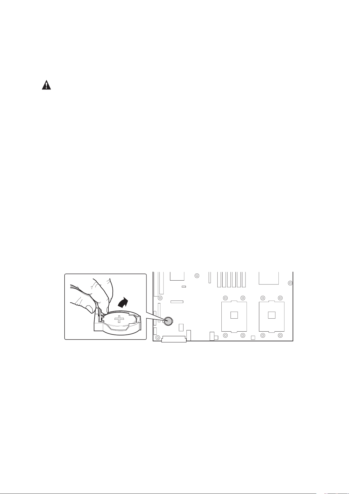
The lithium battery on the server board powers the real time clock (RTC) in the absence
RAM in the RTC (for example, the date and time) may be wrong. Contact
your customer service representative or dealer for a list of approved devices.
WARNING
type recommended by the equipment manufacturer. Discard used batteries according to
To replace the battery:
3.
4.
Page 22

Page 23
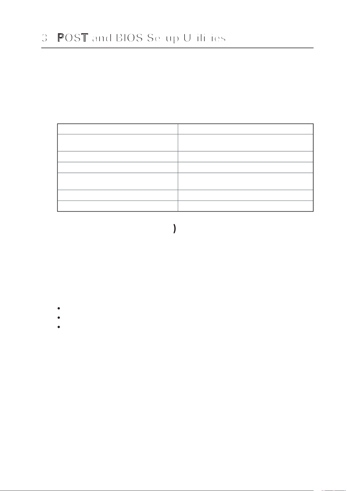
This chapter describes the POST and BIOS setup utilities provided with the MAXDATA
PLATINUM Server Board. It includes information about the Adaptec SCSI Utility and the
Promise FastBuild Utility.
Use the numeric pad of the keyboard to enter numbers and symbols.
Table 4. Hot Keys
To Do This:
the SSU
or BIOS
Setup)
version only)
Abort memory test during POST.
To remove the splash screen.
which is stored in flash memory. POST discovers, configures, and tests the processors,
Turn on your server and monitor. After a few seconds, POST begins to run and displays
While the splash screen is displayed, make one of the following selections:
diagnostic messages and change the boot device priority for
this boot only.
3.
ting system loaded, the boot process continues and the system beeps once. The following
What appears on the screen after this depends on whether you have an operating system
Write down both the screen display and the beep code you hear; this information is useful
for your service representative. For a listing of common beep codes and error messages
that POST can generate, see the “Solving Problems” chapter in this manual.
Page 24

Temporarily Changing the Boot Device Priority
for the current boot process. The
At any time during POST, press <Esc>. When POST completes, a popup Boot menu
3.
first. For example, if you want the server system to boot from the CD-ROM first, you
4.
The Adaptec SCSI Select Utility
The system finds the Adaptec AIC-7902 SCSI host adapter and displays the message
Adaptec AIC-7902 SCSI BIOS V x.xxx where x.xxx is the version number of the SCSISelect
When to Run the Adaptec SCSI Select Utility
When this message appears on the video monitor:
Table 5. SCSI Select Navigation Keys
To
Page 25

The Adaptec AIC-7902 SCSI adapter has two busses. Select the bus from the following
Table 6. Adaptec Main Menu
Options
You have an AIC-7902 adapter in your system.
After selecting the bus, the following menu displays:
Table 7. Menu for each SCSI Channel
Option
Comment
AIC-7902 at Bus:
This menu allows you to format hard disks and/or verify
When you are finished, press <Esc> and make your selection from the following menu:
Table 8. Exit Menu
Option
Comment
Yes
When you finish configuring your SCSI devices, press <Esc>. Then select Yes
and press <Enter>. When this message appears:
Page 26

You can run BIOS Setup with or without an operating system being present. BIOS Setup
stores most of the con guration values in battery-backed CMOS ; the rest of the values are
stored in ash memory. The values take effect when the system is booted. POST
uses these
values to con gure the hardware. If the values and the actual hardware do not agree, POST
generates an error message.
Record your BIOS Setup settings. If default values ever need restoring (after a CMOS clear,
for example), you must run BIOS Setup again. Your record will make this much easier.
memory. To
the reset button down, press the power button. Release both buttons at the same time
You can enter and start Setup under several conditions:
When you turn on the server, after POST completes the memory test
When you have moved the CMOS jumper on the server board to the “Clear CMOS”
Jumper
Warning: CMOS checksum invalid
Warning: CMOS time and date not set
Page 27

Each Setup menu page contains a number of features. Except those used for information
purposes, each feature is associated with a value eld that contains user-selectable
parameters. Parameters may be changed depending upon the security option chosen. If a
value is not changeable due to insuf cient security privileges (or other reasons), the feature’s
value eld becomes inaccessible.
The bottom portion of the Setup screen provides a list of commands that are used for navigating
the Setup utility.
Table 9. Keyboard Commands
←
→
The left and right arrow keys are used to move between the major menu pages. The keys
without displaying the full list.
field for multi-valued features like time and date. If a pick list is displayed, the Enter key will
features of a menu, the parent menu is re-entered. When the ESC key is pressed in any sub-
to where they were before F10 was pressed without affecting any existing values.
Page 28

Table 10. On-Screen Options
When you see this:
What it means:
You cannot change or con gure the option in that menu screen.
appears next to the option.
Page 29

44
The Server Configuration Wizard
(SCW) is a utility that is provided to help you configure
your server. The Server Configuration Wizard is located on the System Resource CD-ROM
The Server Configuration Wizard includes a help system that can be accessed by clicking
the Help button.
When it is first executed, the SCW probes the server for installed devices, firmware, chassis
When you select the options Server Configuration Wizard > Run Wizard, you will be shown
for remote Server Management over a LAN connection will automatically be selected.
Page 30

30
(DPC) Console is part of Intel
®
Server Management
Accessing the server management capabilities of the on-board NIC
A Windows
®
2000 compatible modem
An RS-232 connection to the server‘s Serial B port
Console to verify the state of a server or
with the server hardware. DPC console features allows you to:
(FRU) information
Access a phonebook for remote connection management
There are four DPC
console modes of operation:
mode. Access the DPC console features using the DPC console window menus
over LAN mode. Access the DPC console features using the DPC console window
the DPC
console launches a separate window. The window operates as an ANSI terminal
type in the DPC Console go directly to the server, and the DPC Console displays the text
that you would normally see on the server console.
To use this mode, you must configure the Console Redirection
option of BIOS Setup
for Redirect mode. Enabling Console Redirection requires that the Boot Time Diagnostics
the Console Redirection is either incorrectly configured or disabled, the EMP
is disabled
to function in this mode,
the server must NOT be in graphics mode.
console fails to connect in EMP
within 10 seconds and the server can operate
the DPC Console has successfully connected to the server. This mode allows running
Page 31

31
Console, see the ISM Instal-
The System Setup Utility
(SSU) is located on the System Resource CD-ROM that is shipped
with the server.
View system events
View FRU
information
View sensor data records
or BIOS Setup, you can specify the boot device
The SSU consists of a collection of task-oriented modules plugged into a common frame-
work called the Application Framework (AF). The Application Framework provides a launching
You can run the SSU
from the Server Configuration Utilities menu of the Server Configuration
Wizard, from a set of DOS diskettes, or from the service partition of the hard disk.
from a set of DOS diskettes, you must create the SSU diskettes
from the Resource CD-ROM as follows:
3.
Alternatively, if you have a workstation with the Microsoft
®
Windows
®
operating system,
you can insert the CD into that system and create the diskettes on that system.
When the SSU
starts in the default local execution mode, it accepts input from the keyboard
The SSU supports ROM-DOS version 6.22. The SSU will not operate from a OS box running
®
Page 32

32
using one of the following methods:
following DOS commands:
The mouse driver loads if it is available; press <Enter> to continue.
When the SSU title appears on the screen, press <Enter> to continue.
Working with the SSU Interface
You can access features of the SSU
interface using the mouse or keyboard:
You can have more than one task open at the same time, although some tasks might require
the task as the center of operation until you close the task window.
The SSU
has a build-in help system, which you access by clicking a Help button or choosing
the Help menu.
The SSU
lets you customize your interface using the Preferences section of the main window.
The AF sets these preferences and saves them in the AF.INI file so that they take effect the
which actions each task performs. For a new mode setting to take effect, you must exit
the SSU
and restart it.
to the appropriate language. For a new
from read-only media (CD-ROM, for example), these preferences are lost
when you exit the SSU.
Page 33

33
To change the boot priority of a device:
3.
You can set a user password
The Admin Password button lets you set or change the administrator password used by
All changes to the administrator password take effect immediately.
To change or clear the administrator password:
3.
The User Password
To change or clear the user password:
button.
3.
Page 34

34
To set the security options:
combination that can be used to put the server into secure
forces the server to boot directly into secure mode.
Video Blanking: Enable turns
the power and reset buttons from functioning
when the server is in secure mode. Disable allows the power and reset buttons to
function normally when the server is in secure mode.
3.
Viewing the System Event Log
To view the System Event Log (SEL
When you start the SEL Manager, it automatically loads the current list of events from non-
volatile memory.
3.
Page 35

35
Viewing FRU Information
To view the Field Replaceable Unit
(FRU) information:
When you start the FRU Manager, it automatically loads the current list of events from non-
volatile memory.
The FRU Manager window has a navigation pane on the left that displays, in a tree format,
the inventory of components in the server. The tree has three categories: Chassis, Board, and
the presentation pane in the upper right. The description pane in the lower right displays a
3.
Viewing Sensor Data Records
To view the Sensor Data Record
When you start the SDR Manager, it automatically loads the SDR entries from non-volatile
The SDR Manager window has a navigation pane on the left that displays, in a tree format, the
the information for that SDR in the presentation pane in the upper right. The description
3.
data from the server.
Page 36

36
You can set up the server
You can make the connection over a LAN or by using a modem or direct serial cable to the
(EMP). You can set up the server to notify you when various
To set up the server so you can access it from a remote workstation, you can use either the
To use the Server Configuration Wizard to configure remote LAN access
3.
Always Available: a remote system can initiate a LAN connection, regardless of the server‘s
Page 37

37
to the server using Serial over LAN.
Always Available: an individual can access the server through Serial over LAN if that user
the server Administrator password.
To use the System Setup Utility to configure remote LAN
access:
3.
To require a password for remote access, enter the password in the Enter New Password
4.
Always Available: a remote system can initiate a LAN connection regardless of the state
Page 38

38
To set up the server so you can access it through a
To use the Server Configuration Wizard to configure remote modem or serial access:
3.
4.
word be entered before a user can perform server management functions on this server
from a serial or Modem connection.
Always Active: The EMP is available at any time.
through the Serial port, without using an external modem.
To use the System Setup Utility to configure remote modem or serial access:
3.
To require a password for remote access, enter the password in the Enter New Password
Page 39

39
the modem on the EMP.
Always Active: The EMP is available at any time.
To set up the server so it pages you in the event
To use the Server Configuration Wizard to configure the server to send alerts as telephone
3.
4.
will be automatically selected as a dependency.
Always Active: A connection to the server can be established at any time.
Page 40

40
through the Serial port, without using an external modem.
The valid range is [0 - 255] where 0 disables the blackout period. Setting a blackout
you are done, and then click Continue.
To use the System Setup Utility to set up the server to send alerts as telephone pages:
(Serial B).
Main window, choose Platform Event Manager (PEM).
3.
to the EMP
port (boxes that are not listed here are not required for paging alerts):
automatically sends an
initializes. The maximum length for the string is determined at run-time from
firmware. You will be notified if the string is truncated. Following a save, the actual string
message
you want sent with the page. The maximum length for the paging string is determined
at run-time from rmware. You will be noti ed if the string is truncated. Following a save,
the actual string saved is displayed in the edit box.
Page 41

41
the following buttons:
To send a test page to verify that you have correctly configured PEP, from the Options
To set up the server to send alerts over the LAN
you can use either the SSU or the SCW. For
®
Server Management
To use the Server Configuration Wizard to configure the server to send alerts over the LAN:
3.
4.
server from
a workstation on the LAN.
Page 42

42
Always Available: A remote system can initiate a LAN connection, regardless of the server‘s
to the server using Serial over LAN.
Always Available: An individual can access the server through Serial over LAN if that user
the server Administrator password.
you are done, and then click Continue.
To use the System Setup Utility to configure the server to send alerts over the LAN
3.
4.
receive
alerts from this server. If you want the alert to be broadcast to an entire subnet, enter
the IP address for the subnet
Page 43

43
the following buttons:
When you are setting up your server system,
you can install a service partition onto your
The service partition can be installed either with the Server Configuration Wizard or with the
®
Server Management CD.
your server board.
To install the service partition use the Server Configuration Wizard:
3.
When you click Continue, the existing service partition will be updated.
Page 44

44
After the service partition is installed, you can boot to it by pressing F4 during POST. The
you can save the following configuration information to a file:
to save. You can also restore the information from a saved configuration file.
to a file:
To save the system configuration
from the System Setup Utility:
To save the system configuration from the Server Configuration Wizard:
3.
Page 45

45
To load a previously saved system configuration from a file using the System Setup Utility:
Main window, choose Config Save/Restore. (Configuration Save/Restore
You can load only a configuration that had been previously saved with the SSU.
To restore the system configuration from a file using the Server Configuration Utility:
You can load only a con guration that had been previously saved with the Server Con guration Wizard.
The utility reads the platform type, BIOS revision, and rmware revision from the le and
compares that information with the same information retrieved from the server. If the two
do not match, an error message is displayed and the load operation aborts. If they do match,
the utility saves the con guration data to the server. You will need to reboot your server for
the changes to take effect.
Page 46

46
®
Server Management
®
Server Management.
®
®
Server Management is implemented by installing it within client-
The Service Partition provides you with the ability to remotely access a local partition on the
To get started with Intel
®
Server Management, install the Service Partition first. After the
®
Server Management.
The information here describes installation on a system running a Microsoft
®
Windows
®
®
Server Management
You can install Intel
®
Server Management
on a local server or on a remote workstation that
®
Server Management CD into the system CD-ROM.
3.
®
Server Management CD.
Page 47

47
This chapter helps you identify and solve problems that might occur while you are using
the system.
To do this:
Are all cables correctly connected and secured?
Are the processors fully seated in their sockets on the server board?
Are all add-in PCI boards fully seated in their slots on the server board?
Are all jumper settings on the server board correct?
Are all jumper and switch settings on add-in boards and peripheral devices correct? To
the same interrupt.
Are all DIMMs installed correctly?
Are all peripheral devices installed correctly?
Are all device drivers properly installed?
Are the configuration settings made in BIOS Setup correct?
Are all integrated components from the tested components lists?
Page 48

48
work.
Were all necessary procedures followed and files installed?
Are the correct device drivers installed?
Are you using the software correctly?
After the System Has Been Running Correctly
Problems that occur after the system hardware and software have been running correctly
often indicate equipment failure. Many situations that are easy to correct, however, can also
cause such problems.
the software runs correctly, there may be a problem with the copy on the hard disk drive.
files are installed.
to user commands.)
Page 49

49
This section provides a more detailed approach to identifying a problem and locating its
source.
Preparing the System for Diagnostic Testing
Turn off devices before disconnecting cables: Before disconnecting any peripheral cables
from the system, turn off the system and any external peripheral devices. Failure to do so
Turn off the system and all external peripheral devices. Disconnect all of them from the
3.
Turn on the video monitor. Set its brightness and contrast controls to at least two thirds
4.
Verifying Proper Operation of Key System Lights
As POST
determines the system configuration, it tests for the presence of each mass storage
varies according to the operating system.
This section provides possible solutions for these specific problems:
There are problems with application software.
The bootable CD-ROM is not detected.
Try the solutions in the order given. If you cannot correct the problem, contact your service
Page 50

from the front panel to the server board is loose.
Are there other problems with the system? If so, check the items listed under system
Are the brightness and contrast controls on the video monitor properly adjusted?
Are the video monitor switch settings correct?
Verify that the video controller board is fully seated in the server board connector.
3.
emits
4.
Are the brightness and contrast controls properly adjusted on the video monitor? See
the manufacturer‘s documentation.
Are the video monitor signal and power cables properly installed?
Page 51

the fan status)?
Are the fan power connectors properly connected to the server board?
Are the power supply cables properly connected to the server board?
Are there any shorted wires caused by pinched cables or power connector plugs forced
Are the diskette drive power and signal cables properly installed?
Are all relevant switches and jumpers on the diskette drive set correctly?
Are the power and signal cables to the CD-ROM drive properly installed?
Are all relevant switches and jumpers on the drive set correctly?
Verify that the software is properly configured for the system. See the software installation
Try a different copy of the software to see if the problem is with the copy you are using.
Verify that the server board jumpers are set correctly. See Chapter 6.
Page 52

Verify CD is bootable in another known good CD-ROM drive. (Especially if the CD is a
The server hangs when the drivers are loaded:
The controller stopped working when an add-in adapter was installed:
Try reseating the add in adapter.
The add-in adapter stopped working without apparent cause:
Try reseating the adapter first; then try a different slot if necessary.
The network driver files may be corrupt or deleted. Delete and then reinstall the drivers.
the onboard network controller.
to be installed.
cable (see
your hub documentation for more information on crossover cables).
Page 53
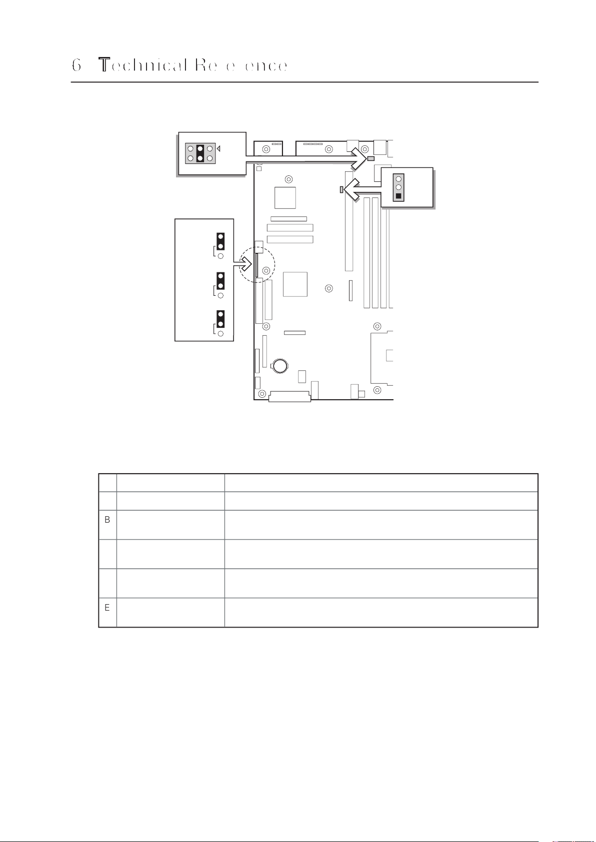
Technical ReferenceTechnical Reference
Table 11. Configuration Jumper
Jumper Name
What it does at system reset
A
Config
settings are cleared. These pins
recovery. These
Boot Block Write
at next reset. These pins should not be jumpered for normal operation.
Page 54

Technical Reference
To help diagnose POST
failures, a set of four bi-color diagnostic LEDs is located on the back
The LED diagnostics feature consists of a hardware decoder and four dual color LEDs. During
the lower nibble is represented by a green LED. If both bits are set in the upper and lower
When comparing a diagnostic LED color string from the baseboard to those listed in the
Table 12. Post Codes
Code
G=Green, R=Red,
A=Amber
Verify password Checksum.
Verify CMOS Checksum.
featured processor as the BSP.
free. Next, issuing the BAT command to the keyboard controller.
tion after the keyboard controller BAT command test.
continued
Page 55

Table 12. Post Codes (continued)
Code
G=Green, R=Red,
A=Amber
Write Command Byte 8042: The initialization after the keyboard
will be written next.
A
the MEGAKEY Green PC feature next. Making the BIOS code seg-
Validate NVRAM areas. Restore from backup if corrupted.
A
Validate date and time in RTC.
A
A
A
continued
Page 56

Technical Reference
Table 12. Post Codes (continued)
Code
G=Green, R=Red,
A=Amber
30h
30h
A
37h
Activate ADM: The display mode is set. Displaying the power-on
37h
37h
A
A
38h
34h
39h
3Ah
A
and saved. Displaying the Hit Setup message next.
40h
and verified. Checking for a soft reset and clearing the memory
A
A
A
A
Test 8237 DMA Controller: The DMA page register test passed.
A
found. Issuing the keyboard controller interface test command
continued
Page 57

Table 12. Post Codes (continued)
Code
G=Green, R=Red,
A=Amber
face test completed. Writing the command byte and initializing the
Verify RAM Size: Checking for a memory size mismatch with
any required programming before Setup next.
A
A
turned control to BIOS POST. Performing any required processing
after the option ROM returned control.
A
A
A
A
Adjust Setup: Programming the Setup options next.
A5h
A7h
A
A7h
A
A7h
A
continued
Page 58

Technical Reference
Table 12. Post Codes (continued)
Code
G=Green, R=Red,
A=Amber
Aah
The following table defines POST error codes and their associated messages. The BIOS prompts
the user to press a key in case of serious errors. Some error messages are preceded by the
word “Error” to highlight the fact that the system might be malfunctioning. All POST errors
Table 13. Standard POST Error Messages and Codes
Timer Channel 2 Error
Yes
Yes
Yes
Yes
Yes
Yes
Yes
Yes
Yes
Yes
Yes
Yes
Yes
Yes
Yes
Yes
Yes
Yes
Yes
Yes
Yes
Yes
continued
Page 59

Table 13. Standard POST Error Messages and Codes (continued)
Yes
Yes
Yes
Yes
Yes
Yes
Yes
Yes
Yes
Yes
Yes
Yes
Yes
Page 60

Technical Reference
Table 14. Extended POST Error Messages and Codes
Yes
Yes
Yes
Yes
Yes
Yes
Watchdog Timer failed on last boot
4:1 Core to bus ratio: Processor Cache disabled
Yes
Yes
Yes
Yes
Yes, Halt
Yes
Yes
Yes
Yes
Yes
Yes
Yes
Yes
Yes
Yes
Yes
Page 61

Table 15. BIOS Recovery Beep Codes
for power-down, reboot.
Table 16. Bootblock Error Beep Codes
The memory refresh circuitry on the motherboard is
faulty.
3
4
The keyboard controller may be bad. The BIOS cannot
The CPU generated an exception interrupt.
The system video adapter is either missing or its memory
Page 62

Technical Reference
Page 63
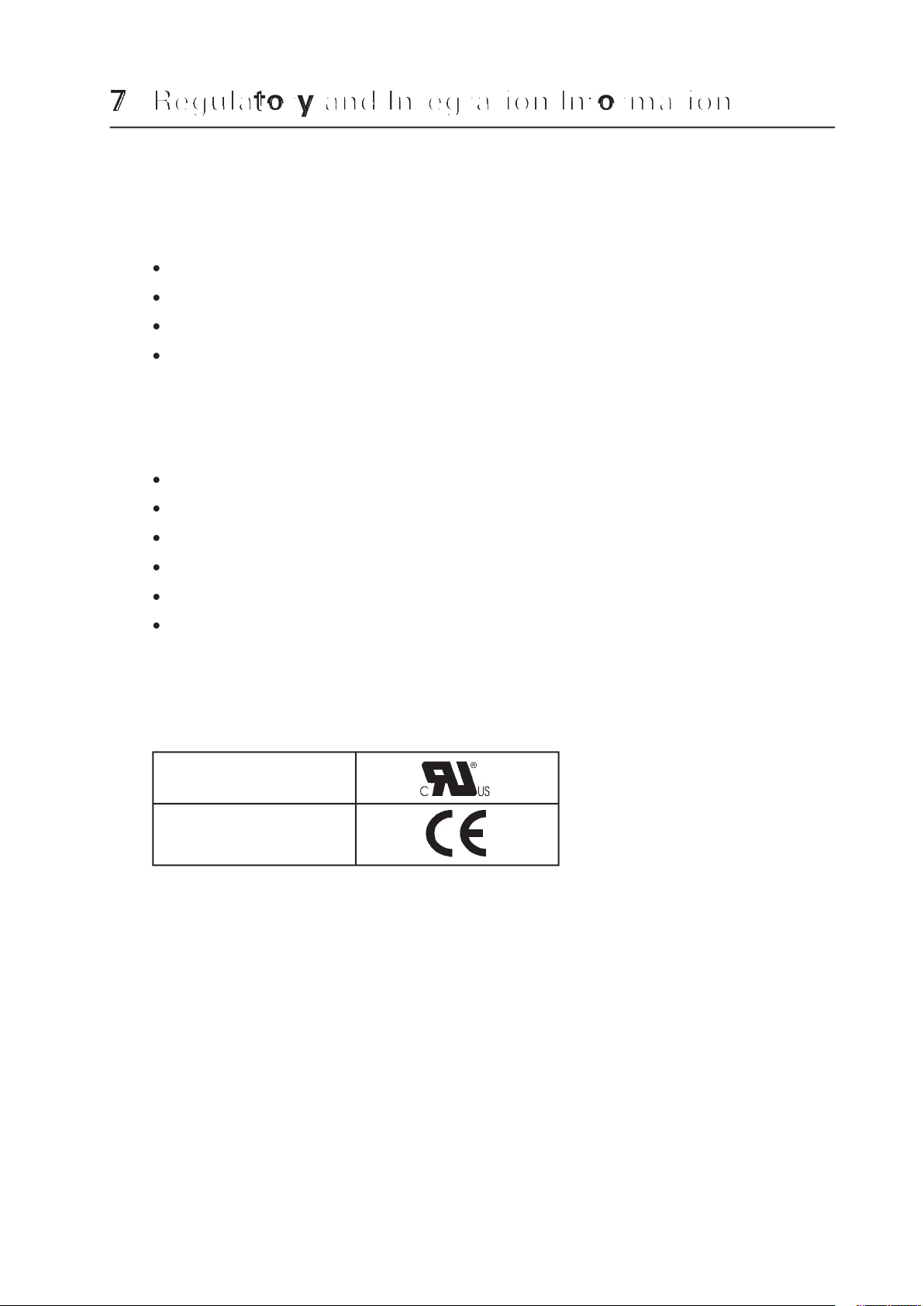
This server board complies with the following safety requirements:
This server board has been tested and verified to comply with the following electromagnetic
This product is marked with the following Product Certification Markings:
CE Mark
Page 64

Electromagnetic Compatibility Notices
This device complies with Part 15 of the FCC Rules. Operation is subject to the following two
This equipment has been tested and found to comply with the limits for a Class A digital
the instructions, may cause harmful interference to radio communications. However, there
Any changes or modifications not expressly approved by the grantee of this device could
void the user’s authority to operate the equipment. The customer is responsible for ensuring
All cables used to connect to peripherals must be shielded and grounded. Operation with
to radio and TV reception.
This product has been tested in accordance too, and complies with the Low Voltage Directive
 Loading...