

Page 1

MAXDATA PLATINUM 50 I M1
User’s Manual
Page 2

2 3MAXDATA PLATINUM 50 I M1Contents
Page 3

Contents
1 Setting up the System 5
Server Position ........................................................................................................................................5
Connecting the System ...........................................................................................................................6
Rear Connectors .................................................................................................................................6
Powering up the System .........................................................................................................................6
2 Board Features 7
Board Components .................................................................................................................................8
Processor ................................................................................................................................................9
Main Memory ..........................................................................................................................................9
Hi-Speed USB 2.0 Support ......................................................................................................................9
Enhanced IDE Interface .........................................................................................................................10
Serial ATA ..............................................................................................................................................10
3 Installing and Replacing Board Components 11
Before You Begin ..................................................................................................................................11
Installation Precautions .........................................................................................................................11
Installing a Processor ............................................................................................................................12
Installing a Processor .......................................................................................................................12
Installing Memory ..................................................................................................................................15
Installing DIMMs ..............................................................................................................................16
Installing and Removing a PCI Express Card .........................................................................................16
Installing a PCI Express Card ............................................................................................................16
Configuring the System for Intel® Matrix Storage Technology for Serial ATA .......................................17
Configuring the BIOS for Intel® Matrix Storage Technology ............................................................17
Creating your RAID set .....................................................................................................................17
Loading the Intel® Application Accelerator Drivers ...........................................................................17
Setting Up a “RAID Ready” System ................................................................................................18
Mainboard Configuration Jumpers ........................................................................................................18
Clear RTC RAM (CLRTC1) ................................................................................................................18
CPU fan pin selection (3-pin FM_CPU1, FM_CPU2) ........................................................................19
Gigabit LAN controller setting (3-pin LAN_EN1) ............................................................................... 19
VGA graphics controller setting (3-pin VGA_EN1) ............................................................................20
RAID select setting (3-pin RAID_SEL1) ............................................................................................20
BIOS recovery (3-pin RECOVERY1) ..................................................................................................21
Replacing the Battery ............................................................................................................................22
BIOS ...................................................................................................................................................... 25
Using the BIOS Setup Program .......................................................................................................25
AMI BIOS beep codes ...........................................................................................................................25
4 Regulatory and Integration Information 27
Product Regulatory Compliance ............................................................................................................27
Product Safety Compliance ..............................................................................................................27
Product EMC Compliance ....................................................................................................................27
Product Regulatory Compliance Markings ............................................................................................27
Electromagnetic Compatibility Notices .................................................................................................27
Europe (CE Declaration of Conformity) ............................................................................................27
Product RoHS Compliance ....................................................................................................................27
Installation Requirements ......................................................................................................................28
Prevent Power Supply Overload ......................................................................................................28
Place Battery Marking ......................................................................................................................28
Use Only for Intended Applications .......................................................................................................28
Page 4

Figures
1. Rear connectors ................................................................................................................................6
2. PLATINUM 50 I Controls ................................................................................................................... 6
3. Board Components ...........................................................................................................................8
4. Lift Socket Lever ............................................................................................................................12
5. Lift the Load Plate and Don’t Touch the Socket Contacts ..............................................................12
6. Remove the Protective Socket Cover .............................................................................................13
7. Remove the Processor from the Protective Processor Cover and Do Not Touch ..........................13
8. Install Processor ..............................................................................................................................14
9. Close the Load Plate .......................................................................................................................14
10. Dual Configuration Example 1 .........................................................................................................15
11. Dual Configuration Example 2 .........................................................................................................15
12. Installing a DIMM ............................................................................................................................16
13. Clear RTCRAM ................................................................................................................................18
14. FM CPU Setting ..............................................................................................................................19
15. LAN_EN1Setting .............................................................................................................................19
16. VGA Setting .....................................................................................................................................20
17. RAID_SEL1 Setting .........................................................................................................................20
18. BIOS Recovery Setting ....................................................................................................................21
19. Removing the Battery .....................................................................................................................24
Tables
1. Feature Summary .............................................................................................................................. 7
2. Board Components ...........................................................................................................................8
3. NIC LEDs ........................................................................................................................................... 9
4. Recommended memory configurations ............................................................................................ 9
5. Serial ATA hard disk drive connection .............................................................................................18
6. AMI BIOS beep codes ....................................................................................................................25
7. Product Certification Markings ........................................................................................................27
4 MFMAXDATA PLATINUM 50 I M1Contents
Page 5
1 Setting up the System
Server Position
Please take note of the following criteria for creating a practical and safe workplace when setting up
your computer:
The system can be used anywhere the temperature is suitable for people. However, rooms
with humidity over 70 %, and dusty or dirty areas are not appropriate. In addition, do not
expose the server to any temperatures over +30 °C or under +10 °C.
Make sure that the cables connecting the server to peripheral devices are not tight.
Make sure that all power and connection cables are positioned so that they are not trip
hazards.
When you save data to your server‘s hard disks or to a floppy disk, they are stored as
magnetic information on the media. Make sure that they are not damaged by magnetic or
electromagnetic fields.
Because the electronics in your computer can be damaged by jarring, no mechanical devices
should be placed on the same surface as the server. This is especially important for impact
printers whose vibrations could damage the hard disk.
ATTENTION
In order to fully separate the server from current, the power cord must be removed from the wall
outlet.
ATTENTION
To ensure stability, the floor stands must be turned outwards.
Page 6
Connecting the System
A
C F
E
G
D
B
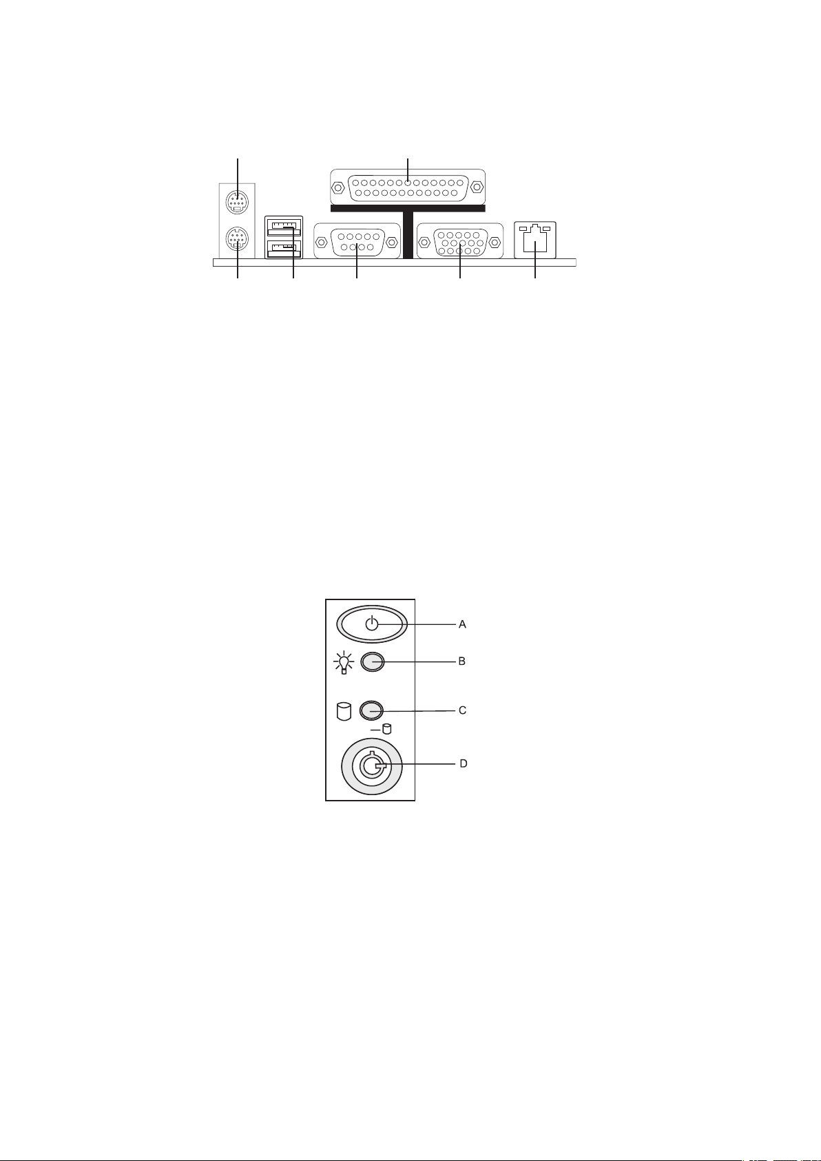
Rear Connectors
A. Mouse E. Serial port
B. Parallel port F. Video
C. Keyboard G. Broadcom BCM 5753 (Gbit LAN)
D. USB 2.0 ports
Figure 1. Rear connectors
Powering up the System
At the front of the case, you can find the necessary controls like power button and the HDD LEDs.
Press the power button one time briefly in order to boot the server.
Figure 2. PLATINUM 50 I Controls
A. Power switch
B. Power LED
C. HDD LED
D. Key Lock
6 MFMAXDATA PLATINUM 50 I M1Setting up the System
Page 7

2 Board Features
This chapter briefly describes the main features of the mainboard.
Table 1 summarizes the major features of the board.
Table 1. Feature Summary
Feature Description
Processors Support for an Intel
MHz or 1066 MHz front side bus
Memory • Four 240-pin, 1.8 V SDRAM Dual Inline Memory Module (DIMM) sockets
• 667/533 MHz single or dual channel DDR2 SDRAM interface
• Designed to support up to 8 GB of system memory
Chipset Intel® E7230 Chipset consisting of:
• Intel
®
E7230 Memory Controller Hub (MCH)
• Intel® 82801GR I/O Controller Hub (ICH7-R)
Peripheral Interfaces • Up to eight USB 2.0 ports
Two ports routed to the back panel
Six ports routed to three USB headers
• Four Serial ATA II channels, via the ICH7-R, supporting Intel
Storage (RAID 0/1/5/10)
• One IDE interface with ATA-66/100 support
• One diskette drive interface
• One parallel port
• Two serial ports, one on the back panel
• PS/2 keyboard and mouse ports
LAN • One Broadcom BCM5753 PCIe Gigabit Ethernet Controller
(10/100/1000 Mbit/s) with RJ-45 connector
Graphics • ATI
®
RAGE-XL PCI-based VGA controller
®
Pentium® 4 processor in the LGA775 package with 800
®
Matrix
Expansion Capabilities • Two 32 bit / 33 MHz / 5 V PCI bus connectors (PCI 2.3)
• One PCI Express x8 connector (x4 link)
• One PCI Express x16 connector (x8 link)
BIOS AMI BIOS
• Support for SMBIOS
• Rapid BIOS Boot
Power Management • Support for Advanced Configuration and Power Interface (ACPI)
• Suspend to RAM (STR)
• Wake on USB, PCI, PCI Express, PS/2, LAN, and front panel
Server Management Hardware monitor with:
• Six fan sensing inputs used to monitor fan activity
• Remote diode temperature sensing
• Precision Cooling Technology fan speed control that automatically
adjusts processor fan speeds based on processor temperature and
chassis fan speeds based on system temperature
• Voltage sensing to detect out of range values
Page 8

Board Components
DIMM_B1
DIMM_
A1
D
IMM_A
2
D
IMM_B
2
A B DCE
F
G
H
I
J
K
L
M
N
O
P
Q
R
S
T
U
V
W
X
Y
Z
AA
BB
CC
DD
EE
FF
GG
HH
II
PCI 1
PCI 2
PCIE 1
PCIE 2
Figure 3 shows the approximate location of the major components on board.
Figure 3. Board Components
Table 2. Board Components
Label Description Label Description
A. Rear Fan 1 S. SATA 4
B. Rear Fan 2 T. SATA 3
C. Conventional PCI Slot 2 U. SATA 2
D. Conventional PCI Slot 1 V. SATA 1
E. PCIE Slot 2 (x8 Connector, x4 Link) W. HDD LED 1
X. Front Fan 2
GG. Chassis Intrusion Connector
HH. Front Panel Connector
F. PCIE Slot 1 (x16 Connector, x8 Link)
G. Back Panel I/O Y. Front Fan 1
H. ATX 12 V Z. Backplane SMBus
I. LGA775 Processor Socket AA. Ambient Thermal Sensor
J. Channel A DIMM 1 Socket (blue) BB. USB 2.0 Ports 7/8
K. Channel A DIMM 2 Socket (black) CC. USB 2.0 Ports 5/6
L. CPU Fan 2 DD. USB 2.0 Ports 3/4
M. Channel B DIMM 1 Socket (blue) EE. Battery
N. Channel B DIMM 2 Socket (black) FF. COM2
O. CPU Fan 1
P. Diskette Drive
Q. IDE II. Standby Power LED
R. ATX Power 1
8 9MAXDATA PLATINUM 50 I M1Board Features
Page 9
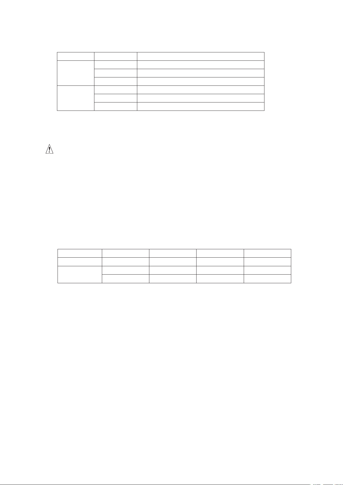
The NIC LEDs at the right and left of the NIC provide the following information:
Table 3. NIC LEDs
LED Color LED State Description
Left LED Off
Green Network connection in place
Blinking Transmit/receive activity
Right LED Off 10 Mbps connection (if left LED is on or blinking)
Red 100 Mbps connection
Green 1000 Mbps connection
No network connection
Processor
The board supports a single Intel® Pentium® 4 Processor in the LGA775 package.
CAUTION
Failure to use an ATX12V power supply or not connecting the 12 V (2 × 2) power connector to the
mainboard may result in damage to the board and/or power supply.
Main Memory
The mainboard supports dual or single channel memory configurations defined in Table 4. 256 MB,
512 MB, 1 GB, and 2 GB unbuffered ECC/non-ECC DDR2 533/667 MHz DIMMs can be installed.
NOTE
When installing one or two DIMMs, install the DIMM(s) to the blue slots (DIMM_A2/DIMM_B2). Use
only identical DDR2 DIMM pairs for Dual channel configurations.
Table 4. Recommended memory configurations
Mode DIMM_A1 (blue) DIMM_A2 (black) DIMM_B1 (blue) DIMM_B2 (black)
Single-channel
Dual-channel*
* Use only identical DDR2 DIMM pairs.
Installed – – –
Installed – Installed –
Installed Installed Installed Installed
NOTE
System resources (such as PCI and PCI Express) require physical memory address locations that
reduce available memory addresses above 3 GB. As a result of this, less than the installed memory
may be available to the operating system and applications if more than 3 GB of memory are installed
in the system.
Hi-Speed USB 2.0 Support
NOTE
Computer systems that have an unshielded cable attached to a USB port might not meet FCC Class
B requirements, even if no device or a low-speed USB device is attached to the cable. Use a shielded
cable that meets the requirements for a full-speed USB device.
The board supports up to eight USB 2.0 ports via ICH6-R; four ports routed to the back panel and
four routed to two internal USB 2.0 headers. USB 2.0 ports are backward compatible with USB 1.1
devices. USB 1.1 devices will function normally at USB 1.1 speeds.
USB 2.0 support requires both an operating system and drivers that fully support USB 2.0 transfer
rates. Disabling Hi-Speed USB in BIOS reverts all USB 2.0 ports to USB 1.1 operation. This may be
required to accommodate operating systems that do not support USB 2.0.
Page 10

Enhanced IDE Interface
The ICH7R’s IDE interface handles the exchange of information between the processor and peripheral
devices like hard disks, CD-ROM drives, and Iomega Zip drives inside the computer. The interface
supports:
• Up to two IDE devices (such as hard drives)
• ATAPI-style devices (such as CD-ROM drives)
• Older PIO Mode devices
• Ultra DMA-33 and ATA-66/100 protocols
• Laser Servo (LS-120) drives
Serial ATA
The board supports four Serial ATA channels via the ICH7R, connecting one device per channel in
either a RAID or non-RAID configuration.
10 MFMAXDATA PLATINUM 50 I M1Board Features
Page 11

3 Installing and Replacing Board Components
Before You Begin
WARNING
The procedures in this chapter assume familiarity with the general terminology associated with
personal computers and with the safety practices and regulatory compliance required for using and
modifying electronic equipment.
Disconnect the computer from its power source and from any telecommunications links, networks,
or modems before performing any of the procedures described in this chapter. Failure to disconnect
power, telecommunications links, networks, or modems before you open the computer or perform
any procedures can result in personal injury or equipment damage. Some circuitry on the board can
continue to operate even though the front panel power button is off.
Follow these guidelines before you begin:
• Always follow the steps in each procedure in the correct order.
• Set up a log to record information about your computer, such as model, serial numbers,
installed options, and configuration information.
• Electrostatic discharge (ESD) can damage components. Perform the procedures described in
this chapter only at an ESD workstation using an antistatic wrist strap and a conductive foam
pad. If such a station is not available, you can provide some ESD protection by wearing an
antistatic wrist strap and attaching it to a metal part of the computer chassis.
Installation Precautions
When you install or exchange hardware components, observe all warnings and cautions in the
installation instructions.
To avoid injury, be careful of:
• Sharp pins on connectors
• Sharp pins on printed circuit assemblies
• Rough edges and sharp corners on the chassis
• Hot components (like processors, voltage regulators, and heat sinks)
• Damage to wires that could cause a short circuit
Observe all warnings and cautions that instruct you to refer computer servicing to qualified technical
personnel.
NOTE
The motherboard comes with a standby power LED. The green LED lights up to indicate that the
system is ON, in sleep mode, or in soft-off mode. This is a reminder that you should shut down the
system and unplug the power cable before removing or plugging in any motherboard component.
Page 12
Installing a Processor
Instructions on how to install the processor to the board are given below.
Installing a Processor
CAUTION
Before installing or removing the processor, make sure that AC power has been removed by unplugging
the power cord from the computer; the standby power LED should not be lit Failure to do so could
damage the processor and the board.
To install a processor, follow these instructions:
1. Observe the precautions in “Before You Begin”.
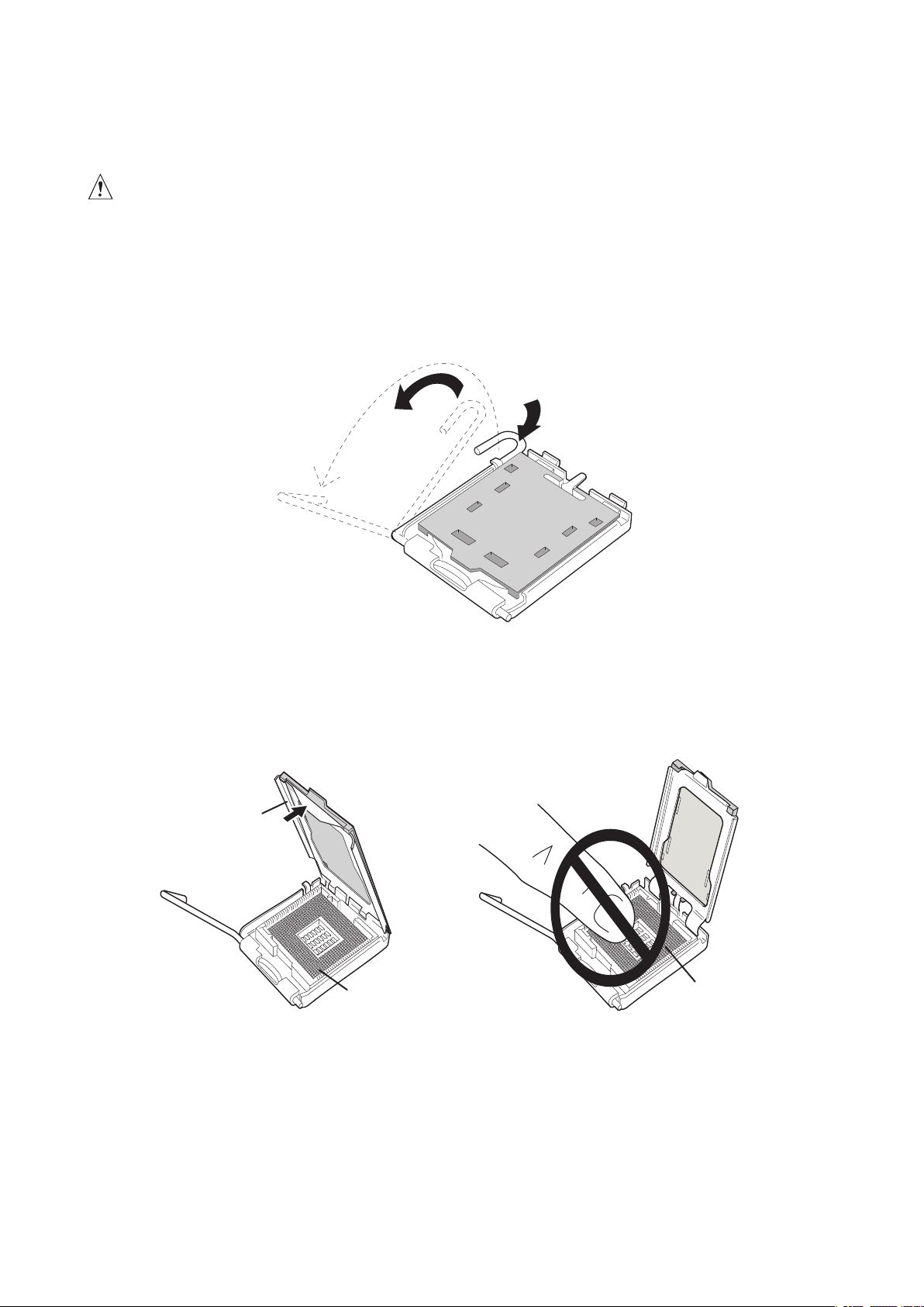
2. Open the socket lever by pushing the lever down and away from the socket (see Figure 4, A
and B).
Figure 4. Lift Socket Lever
3. Lift the load plate. Do not touch the socket contacts (see Figure 5, C and D)
Figure 5. Lift the Load Plate and Don’t Touch the Socket Contacts
12 13MAXDATA PLATINUM 50 I M1Installing and Replacing Board Components
Page 13
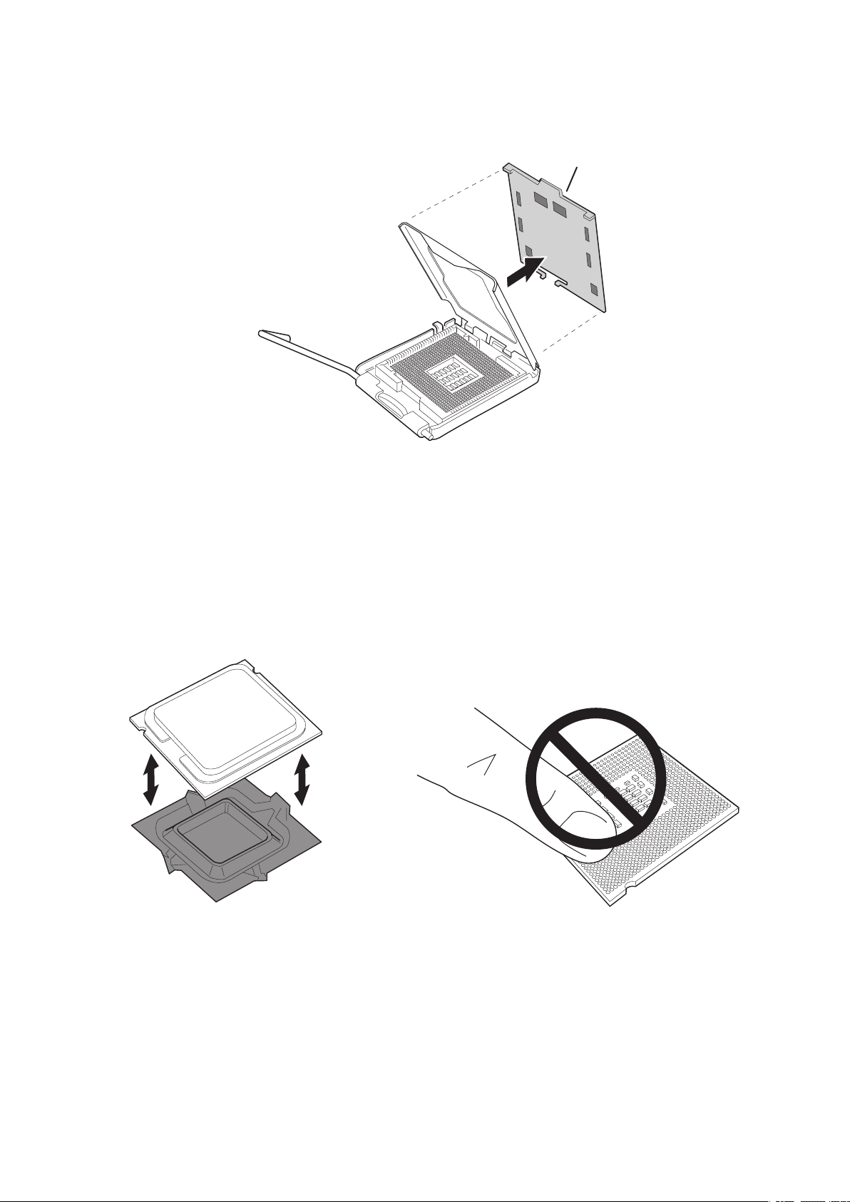
4. Remove the protective socket cover from the load plate. Do not discard the protective socket
�
cover. Always replace the socket cover if the processor is removed from the socket (see
Figure 6, E).
Figure 6. Remove the Protective Socket Cover
5. Remove the processor from the protective processor cover. Hold the processor only at the
edges, being careful not to touch the bottom of the processor. Do not discard the protective
processor cover. Always replace the processor cover if the processor is removed from the
socket (see Figure 7).
Figure 7. Remove the Processor from the Protective Processor Cover and Do Not Touch
Page 14
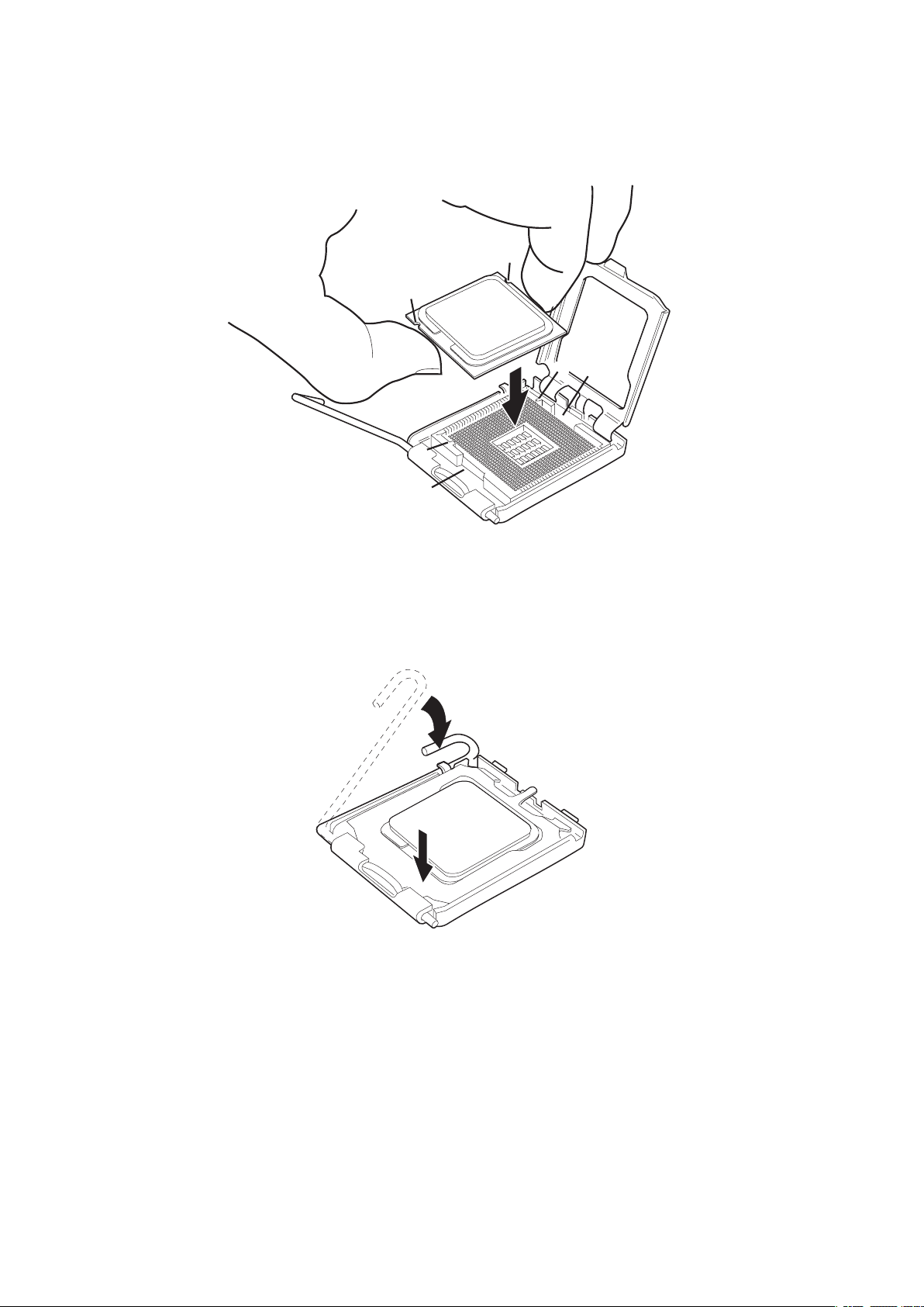
6. Hold the processor with your thumb and index fingers oriented as shown in Figure 8. Make
sure fingers align to the socket cutouts (see Figure 8, F). Align notches (see Figure 8, G) with
the socket see (Figure 8, H). Lower the processor straight down without tilting or sliding the
processor in the socket.
Figure 8. Install Processor
7. Pressing down on the load plate (Figure 9, I) close and engage the socket lever (Figure 9, J).
Figure 9. Close the Load Plate
14 15MAXDATA PLATINUM 50 I M1Installing and Replacing Board Components
Page 15

Installing Memory
The board has four 240-pin DIMM sockets arranged as DIMM 1 and DIMM 2 in both Channel A and
Channel B, as shown in Figure 3.
Guidelines for Dual Channel Memory Configuration
Before installing DIMMs, read and follow these guidelines for dual channel configuration.
Two or Four DIMMs
Install a matched pair of DIMMs equal in speed and size (see Figure 10) in DIMM 1 (blue) of both
channels A and B.
Channel A
1 GB, 533 MHz DIMM 1
DIMM 2
Channel B
1 GB, 533 MHz DIMM 1
DIMM 2
Figure 10. Dual Configuration Example 1
If additional memory is to be used, install another matched pair of DIMMs in DIMM 2 (black) in both
channels A and B (see Figure 11).
Channel A
256 MB, 533 MHz DIMM 1
512 MB, 533 MHz
DIMM 2
Channel B
256 MB, 533 MHz DIMM 1
512 MB, 533 MHz
Figure 11. Dual Configuration Example 2
DIMM 2
Page 16
Installing DIMMs
To install DIMMs, follow these steps:
1. Observe the precautions in “Before You Begin” on page 11.
2. Turn off all peripheral devices connected to the computer. Turn off the computer and
disconnect the AC power cord.
3. Remove the computer’s cover and locate the DIMM sockets (see figure 3).
4. Make sure the clips at either end of the DIMM socket(s) are pushed outward to the open
position.
5. Holding the DIMM by the edges, remove it from its anti-static package.
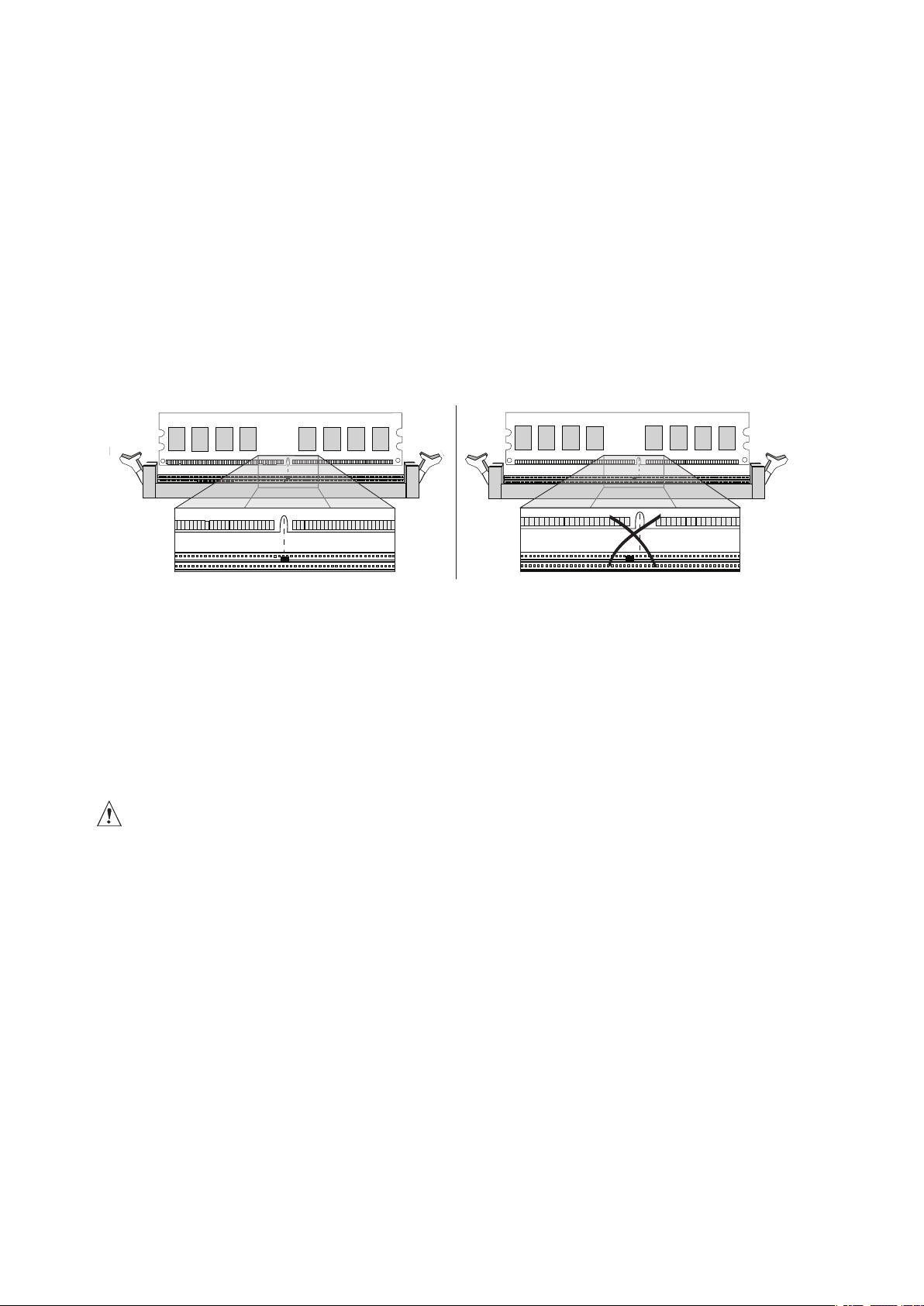
6. Position the DIMM above the socket. Align the small notch at the bottom edge of the DIMM
with the keys in the socket (see Figure 12).
7. Insert the bottom edge of the DIMM into the socket.
Figure 12. Installing a DIMM
8. When the DIMM is inserted, push down on the top edge of the DIMM until the retaining clips
snap into place. Make sure the clips are firmly in place.
9. Replace the computer’s cover and reconnect the AC power cord.
Installing and Removing a PCI Express Card
CAUTION
When installing any PCI Express card on the board, ensure that it is fully seated in the PCI Express
connector before you power on the system. If the card is not fully seated in the PCI Express connector,
an electrical short may result across the PCI Express connector pins. Depending on the over-current
protection of the power supply, certain board components and/or traces may be damaged.
Installing a PCI Express Card
Follow these instructions to install a PCI Express card:
1. Observe the precautions in “Before You Begin”.
2. Place the card in the PCI Express connector.
3. Press down on the card until it is completely seated in the connector.
4. Secure the card’s metal bracket to the chassis back panel with a screw.
16 17MAXDATA PLATINUM 50 I M1Installing and Replacing Board Components
Page 17

Configuring the System for Intel® Matrix Storage Technology
for Serial ATA
Configuring the BIOS for Intel® Matrix Storage Technology
1. Assemble your system and attach two SATA hard drives.
2. Enter system BIOS Setup by pressing the <F2> key after the Power-On-Self-Test (POST)
memory tests begin.
3. Go to “Main” > “IDE Configuration”; make sure “Configure SATA As” is set to “RAID”.
4. Then save your settings by pressing <F10>.
Creating your RAID set
1. Upon re-boot you will see the Intel® Matrix Storage Manager Option ROM status message on
the screen. Press CTRL-I to enter the RAID Option ROM user interface.
2. In the User Interface menu, select option #1; Create RAID Volume. Enter a volume name,
press <enter>.
NOTE
The RAID Volume name must be in English alphanumeric ASCII characters.
3. Use the arrow keys to select RAID 0 or RAID 1, press <enter>.
4. Select the drives to be used in the RAID array (only if there are more than two drives available),
press <enter>.
5. Select the stripe size (only for RAID 0), and press <enter>.
6. Enter the size of the volume (If you select less than the maximum volume size you can then
create a second RAID array on the remaining portion of your volume), and press <enter>.
7. Finally press <Y> to confirm your selections.
8. Exit the Option ROM user interface by pressing <esc>.
Loading the Intel® Application Accelerator Drivers
NOTE
A floppy disk with the RAID driver is required when installing the operating system on a RAID set.
You can create a RAID driver disk from the mainboard resource CD. Either boot the CD and follow
the instructions on the screen or run the program located in the drivers directory under Windows to
create the driver disk.
®
1. Begin Microsoft
2. At the beginning of Microsoft
RAID driver. When prompted, insert the floppy disk with the RAID driver. Install the Intel®
82801GR/GH SATA RAID Controller driver.
3. Finish the Microsoft
4. Install the Intel
with your motherboard or after downloading it from the Internet. This will add the Intel®
Storage Utility which can be used to manage the RAID configuration.
Windows® Setup by booting from the Microsoft® Windows® installation CD.
®
Windows® Setup, press <F6> to install a third-party SCSI or
®
Windows® installation and install all necessary drivers.
®
Application Accelerator software via the Intel® Express Installer CD included
Page 18
Setting Up a “RAID Ready” System
CLRTC1
2
1
3
2
The Intel® Application Accelerator software offers the flexibility to upgrade from a single Serial ATA
drive to RAID without reinstalling the Operating System (OS), when a second SATA hard drive is
added to the system.
®
Follow the steps described in “Configuring the BIOS for Intel
“Loading the Intel® Application Accelerator Drivers”.
Table 5. Serial ATA hard disk drive connection
Connector Setting Use
SATA1 / SATA2
SATA3 / SATA4
Master Boot Disk
Slave Data Disk
Matrix Storage Technology” and
Mainboard Configuration Jumpers
Clear RTC RAM (CLRTC1)
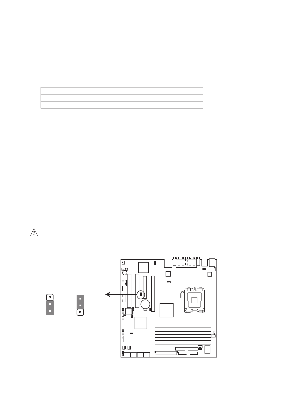
This jumper allows you to clear the Real Time Clock (RTC) RAM in CMOS. You can clear the CMOS
memory of system setup parameters by erasing the CMOS RTC RAM data. The onboard button cell
battery powers the RAM data in CMOS, which include system setup information such as system
passwords.
To erase the RTC RAM:
1. Turn OFF the computer and unplug the power cord.
2. Remove the onboard battery.
3. Move the jumper cap from pins 1-2 (default) to pins 2-3. Keep the cap on pins 2-3 for about 5
to 10 seconds, then move the cap back to pins 1-2.
4. Re-install the battery.
5. Plug the power cord and turn ON the computer.
6. Hold down the <Del> key during the boot process and enter BIOS setup to re-enter data.
CAUTION
Except when clearing the RTC RAM, never remove the cap on CLRTC jumper default position.
Removing the cap will cause system boot failure!
Normal (Default)
18 19MAXDATA PLATINUM 50 I M1Installing and Replacing Board Components
ClearCMOS
Figure 13. Clear RTCRAM
Page 19
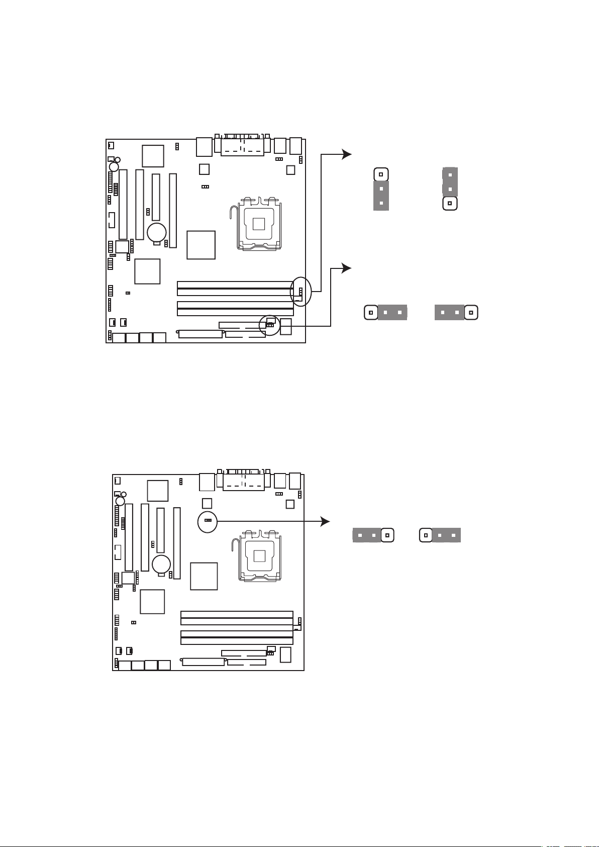
CPU fan pin selection (3-pin FM_CPU1, FM_CPU2)
FM_CPU1
FM_CPU2
2
3
2
1
2
1
2
3
LAN_EN1
2
1
2
3
These jumpers allow you to connect either a 3-pin or a 4-pin fan cable plug to the CPU fan connectors
(CPU_FAN1, CPU_FAN2). Set these jumpers to pins 1-2 if you are using a 3-pin fan cable plug, or to
pins 2-3 if you are using a 4-pin plug.
3-pin fan
3-pin fan
Figure 14. FM CPU Setting
4-pin fan
(Default)
4-pin fan
(Default)
Gigabit LAN controller setting (3-pin LAN_EN1)
This jumper allows you to enable or disable the onboard Broadcom BCM5753 Gigabit LAN controller.
Set to pins 1-2 to activate the Gigabit LAN feature.
Enable
(Default)
Figure 15. LAN_EN1 Setting
Disable
Page 20
VGA_EN1
2
1
2
3
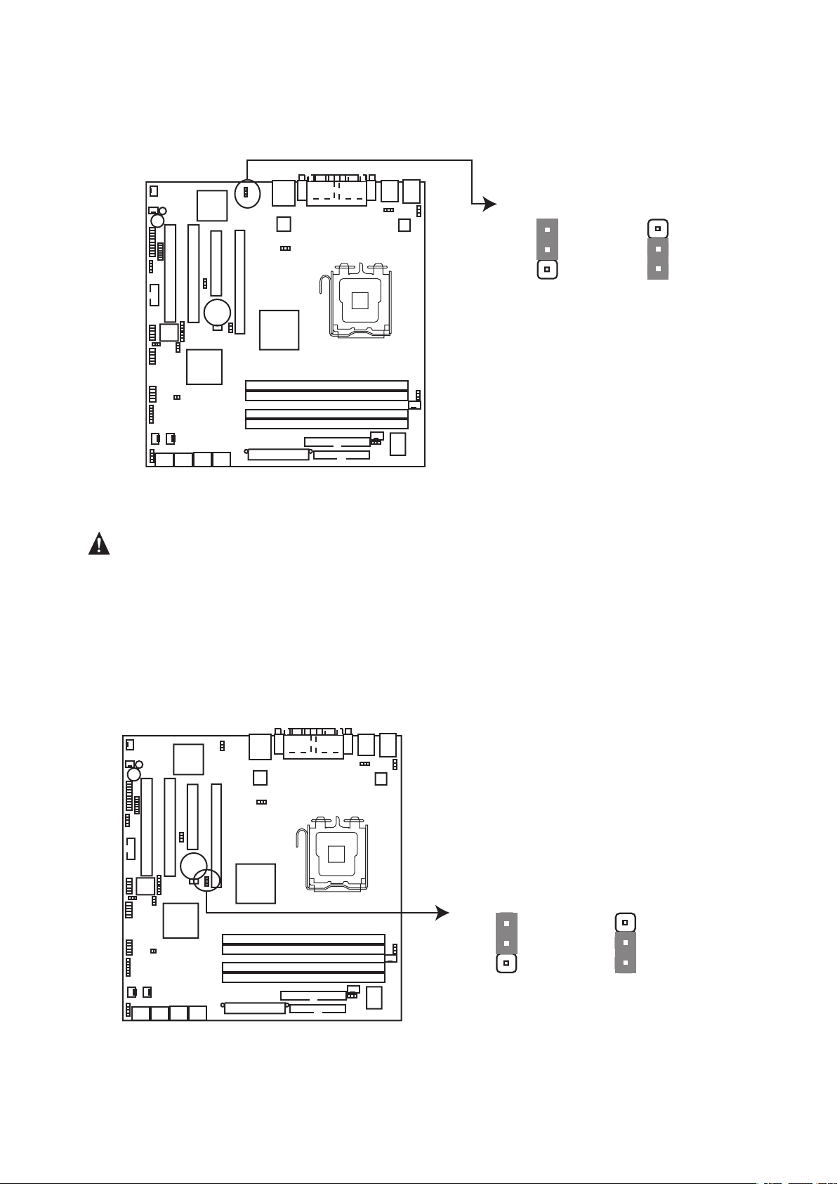
VGA graphics controller setting (3-pin VGA_EN1)
RAID_SEL1
2
1
2
3
This jumper allows you to enable or disable the onboard ATI Rage XL video graphics controller. Set
to pins 1-2 to enable the video graphics controller.
Enable (Default)
Figure 16. VGA Setting
Caution
Make sure to set this jumper to Disable if you want to install VGA cards on the PCI and PCI Express
slots.
RAID select setting (3-pin RAID_SEL1)
This jumper must always be installed to 2-3 to enable Intel® RAID ROM. Jumper setting 1-2 is not
supported.
Disable
(not supported) INTEL RAID ROM
Figure 17. RAID_SEL1 Setting
20 21MAXDATA PLATINUM 50 I M1Installing and Replacing Board Components
Page 21
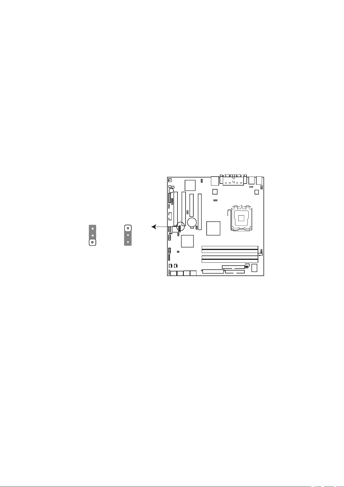
BIOS recovery (3-pin RECOVERY1)
2
3
2
1
This jumper allows you to recover your original BIOS from a floppy disk in case the BIOS codes and
data get corrupted.
To recover the BIOS:
1. Turn OFF your computer and unplug the power cord.
2. Move the jumper cap from pins 1-2 (default) to pins 2-3.
3. Insert a floppy disk with the original or updated BIOS file.
4. Plug the power cord and turn ON the computer.
5. The system searches for the BIOS file in the floppy then reflashes the BIOS.
6. When finished, shut down your computer.
7. Replace the jumper cap from pins 2-3 to pins 1-2.
8. Reboot your computer.
9. Hold down the <Del> key during the boot process and enter BIOS setup to re-enter data.
RECOVERY1
Normal
(Default)
BIOS recovery
Figure 18. BIOS Recovery Setting
Page 22

Replacing the Battery
A coin-cell battery (CR2032) powers the real-time clock and CMOS memory. When the computer is
not plugged into a wall socket, the battery has an estimated life of three years. When the computer
is plugged in, the standby current from the power supply extends the life of the battery. The clock is
accurate to ± 13 minutes/year at 25 ºC with 3.3 VSB applied.
When the voltage drops below a certain level, the BIOS Setup program settings stored in CMOS
RAM (for example, the date and time) might not be accurate. Replace the battery with an equivalent
one. Figure 15 on page 23 shows the location of the battery.
CAUTION
Risk of explosion if the battery is replaced with an incorrect type. Batteries should be recycled
where possible. Disposal of used batteries must be in accordance with local environmental
regulations.
PRÉCAUTION
Risque d’explosion si la pile usagée est remplacée par une pile de type incorrect. Les piles
usagées doivent être recyclées dans la mesure du possible. La mise au rebut des piles
usagées doit respecter les réglementations locales en vigueur en matière de protection de
l’environnement.
FORHOLDSREGEL
Eksplosionsfare, hvis batteriet erstattes med et batteri af en forkert type. Batterier bør om
muligt genbruges. Bortskaffelse af brugte batterier bør foregå i overensstemmelse med
gældende miljølovgivning.
OBS!
Det kan oppstå eksplosjonsfare hvis batteriet skiftes ut med feil type. Brukte batterier bør
kastes i henhold til gjeldende miljølovgivning.
VIKTIGT!
Risk för explosion om batteriet ersätts med felaktig batterityp. Batterier ska kasseras enligt
de lokala miljövårdsbestämmelserna.
VARO
Räjähdysvaara, jos pariston tyyppi on väärä. Paristot on kierrätettävä, jos se on mahdollista.
Käytetyt paristot on hävitettävä paikallisten ympäristömääräysten mukaisesti.
VORSICHT
Bei falschem Einsetzen einer neuen Batterie besteht Explosionsgefahr. Die Batterie darf
nur durch denselben oder einen entsprechenden, vom Hersteller empfohlenen Batterietyp
ersetzt werden. Entsorgen Sie verbrauchte Batterien den Anweisungen des Herstellers
entsprechend.
AVVERTIMENTO
Esiste il pericolo di un esplosione se la pila non viene sostituita in modo corretto. Utilizzare
solo pile uguali o di tipo equivalente a quelle consigliate dal produttore. Per disfarsi delle pile
usate, seguire le istruzioni del produttore.
PRECAUCIÓN
Existe peligro de explosión si la pila no se cambia de forma adecuada. Utilice solamente pilas
iguales o del mismo tipo que las recomendadas por el fabricante del equipo. Para deshacerse
de las pilas usadas, siga igualmente las instrucciones del fabricante.
WAARSCHUWING
Er bestaat ontploffingsgevaar als de batterij wordt vervangen door een onjuist type batterij.
Batterijen moeten zoveel mogelijk worden gerecycled. Houd u bij het weggooien van gebruikte
batterijen aan de plaatselijke milieuwetgeving.
22 23MAXDATA PLATINUM 50 I M1Installing and Replacing Board Components
Page 23

ATENÇÃO
Haverá risco de explosão se a bateria for substituída por um tipo de bateria incorreto. As
baterias devem ser recicladas nos locais apropriados. A eliminação de baterias usadas deve
ser feita de acordo com as regulamentações ambientais da região.
UPOZORNÌNÍ
V případě výměny baterie za nesprávný druh může dojít k výbuchu. Je-li to možné, baterie by
měly být recyklovány. Baterie je třeba zlikvidovat v souladu s místními předpisy o životním
prostředí.
Προσοχή
Υπάρχει κίνδυνος για έκρηξη σε περίπτωση που η µπαταρία αντικατασταθεί
από µία λανθασµένου τύπου. Οι µπαταρίες θα πρέπει να ανακυκλώνονται
όταν κάτι τέτοιο είναι δυνατό. Η απόρριψη των χρησιµοποιηµένων µπαταριών
πρέπει να γίνεται σύµφωνα µε τους κατά τόπο περιβαλλοντικούς κανονισµούς.
VIGYAZAT
Ha a telepet nem a megfelelő típusú telepre cseréli, az felrobbanhat. A telepeket lehetőség
szerint újra kell hasznosítani. A használt telepeket a helyi környezetvédelmi előírásoknak
megfelelően kell kiselejtezni.
AWAS
Risiko letupan wujud jika bateri digantikan dengan jenis yang tidak betul. Bateri sepatutnya
dikitar semula jika boleh. Pelupusan bateri terpakai mestilah mematuhi peraturan alam sekitar
tempatan.
OSTRZEŻENIE
Istnieje niebezpieczeństwo wybuchu w przypadku zastosowania niewłaściwego typu baterii.
Zużyte baterie należy w miarę możliwości utylizować zgodnie z odpowiednimi przepisami
ochrony środowiska.
PRECAUŢIE
Risc de explozie, dacă bateria este înlocuită cu un tip de baterie necorespunzător. Bateriile
trebuie reciclate, dacă este posibil. Depozitarea bateriilor uzate trebuie să respecte reglementările
locale privind protecţia mediului.
UPOZORNENIE
Ak batériu vymeníte za nesprávny typ, hrozí nebezpečenstvo jej výbuchu. Batérie by sa mali
podľa možnosti vždy recyklovať. Likvidácia použitých batérií sa musí vykonávať v súlade s
miestnymi predpismi na ochranu životného prostredia.
POZOR
Zamenjava baterije z baterijo drugačnega tipa lahko povzroči eksplozijo. Če je mogoče, baterije
reciklirajte. Rabljene baterije zavrzite v skladu z lokalnimi okoljevarstvenimi predpisi.
Page 24
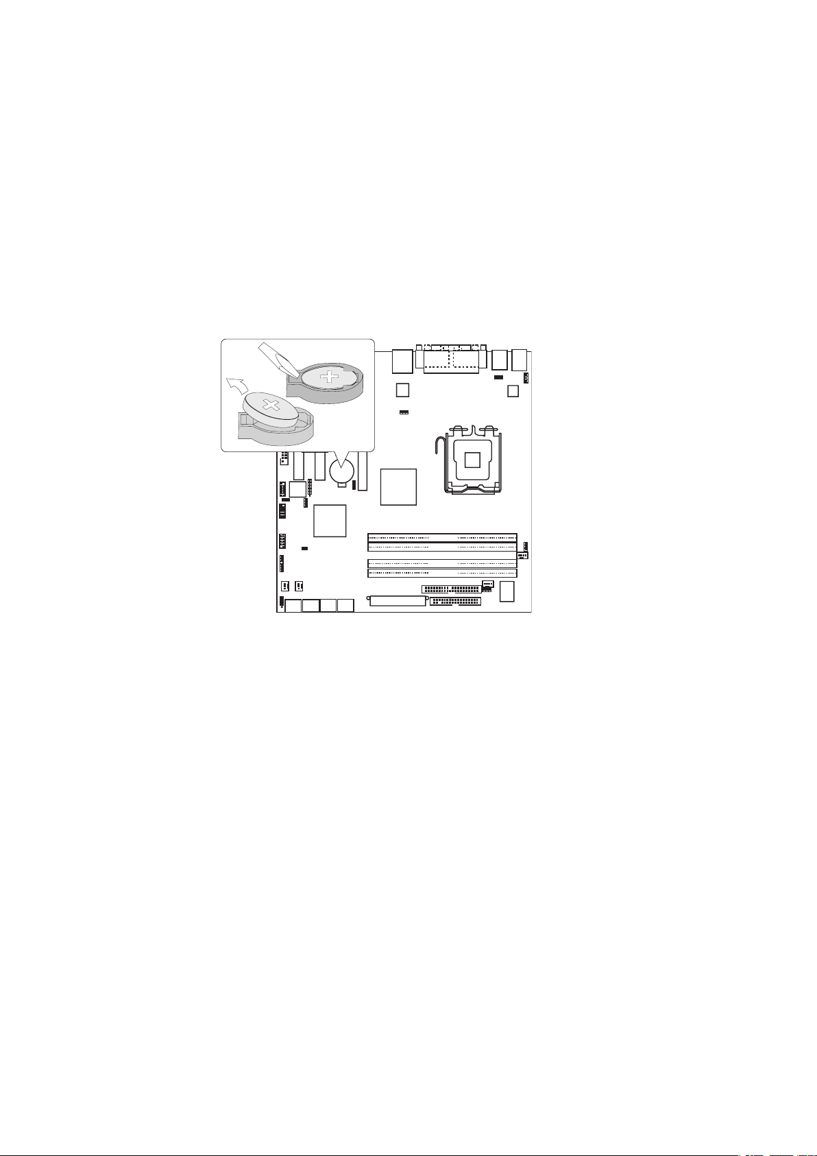
To replace the battery, follow these steps:
D I M M _
B
1
D I M M _ A 1
D I M
M _ A
2
D I M M
_ B 2
1. Observe the precautions in “Before You Begin” on page 11.
2. Turn off all peripheral devices connected to the computer. Disconnect the computer’s power
cord from the AC power source (wall outlet or power adapter).
3. Remove the computer cover.
4. Locate the battery on the board (see Figure 19).
5. With a medium flat-bladed screwdriver, gently pry the battery free from its connector. Note the
orientation of the “+” and “-” on the battery.
6. Install the new battery in the connector, orienting the “+” and “-” correctly.
7. Replace the computer cover.
Figure 19. Removing the Battery
24 25MAXDATA PLATINUM 50 I M1Installing and Replacing Board Components
Page 25

BIOS
Using the BIOS Setup Program
The BIOS Setup program is accessed by pressing the <Del> key after the Power-On Self-Test (POST)
memory test begins and before the operating system boot begins.
When you enter the BIOS Setup program, the Main menu screen appears, giving you an overview of
the basic system information. At the bottom right corner of a menu screen are the navigation keys
for that particular menu. Use the navigation keys to move between menus, select items in a menu
and change the settings. A solid triangle before an item indicates that the item has a sub-menu. To
display the sub-menu, select the item and press <Enter> to enter the submenu. A configurable field
is enclosed in brackets, and is highlighted when selected. To change the value of a field, select it
then press <Enter> to display a list of options. A scroll bar appears on the right side of a menu screen
when there are items that do not fit on the screen. Press the Up / Down arrow keys or <Page Up> /
<Page Down> keys to display the other items on the screen.
AMI BIOS beep codes
When a recoverable error occurs during the POST, the BIOS displays an error message describing
the problem.
Table 6. AMI BIOS beep codes
Beep Description Error
One beep Keyboard controller error
Refresh Time error
No master drive detected
Two continuous beeps followed by
two short beeps
Two continuous beeps followed by
four short beeps
Floppy controller failure
Hardware component failure
Additional messages may appear on the screen indicating the cause of a POST error.
Page 26

26
Page 27
4 Regulatory and Integration Information
Product Regulatory Compliance
Product Safety Compliance
The server board complies with the following safety requirements:
• EN 60950 (European Union)
• IEC 60950 (International)
• CE – Low Voltage Directive (73/23/EEC) (European Union)
Product EMC Compliance
The server board has been has been tested and verified to comply with the following electromagnetic
compatibility (EMC) regulations when installed a compatible host system.
• CISPR 22, 3rd Edition (Class A) – Radiated & Conducted Emissions (International)
• EN 55022 (Class A) – Radiated & Conducted Emissions (European Union)
• EN 55024 (Immunity) (European Union)
• CE – EMC Directive (89/336/EEC) (European Union)
Product Regulatory Compliance Markings
This product is marked with the following Product Certification Markings:
Table 7. Product Certification Markings
CE Mark
Electromagnetic Compatibility Notices
Europe (CE Declaration of Conformity)
This product has been tested in accordance to, and complies with the Low Voltage Directive (73/23/
EEC) and EMC Directive (89/336/EEC). The product has been marked with the CE Mark to illustrate
its compliance.
Product RoHS Compliance
Restriction of Hazardous Substances: This server system is compliant to European Directive 2002 /
95 / EC (RoHS).
Page 28

Installation Requirements
CAUTION
Follow these guidelines to meet safety and regulatory requirements when installing this board
assembly.
Read and adhere to all of these instructions and the instructions supplied with the chassis and
associated modules. If the instructions for the chassis are inconsistent with these instructions or
the instructions for associated modules, contact the supplier’s technical support to find out how you
can ensure that your computer meets safety and regulatory requirements. If you do not follow these
instructions and the instructions provided by chassis and module suppliers, you increase safety risk
and the possibility of noncompliance with regional laws and regulations.
Prevent Power Supply Overload
Do not overload the power supply output. To avoid overloading the power supply, make sure that the
calculated total current loads of all the modules within the computer is less than the output current
rating of each of the power supplies output circuits.
Place Battery Marking
There is insufficient space on this server board to provide instructions for replacing and disposing of
the battery. For system safety certification, the following statement or equivalent statement may be
required to be placed permanently and legibly on the chassis near the battery.
CAUTION
Risk of explosion if battery is incorrectly replaced.
Replace with only the same or equivalent type recommended by the manufacturer. Dispose of used
batteries according to the manufacturer’s instructions.
Use Only for Intended Applications
This server board was evaluated as Information Technology Equipment (I.T.E.) for use in computers
that will be installed in offices, homes, schools, computer rooms, and similar locations. The suitability
of this product for other applications or environments, (such as medical, industrial, alarm systems,
test equipment, etc.) may require further evaluation.
28 MFMAXDATA PLATINUM 50 I M1Regulatory and Integration Information
 Loading...