

Page 1

FOREWORD
This section must be read before any connection is made
to the mains supply.
WARNINGS
Do not expose the equipment to rain or moisture.
Do not remove the cover from the equipment.
Do not push anything inside the equipment through
the ventilation holes.
COPYRIGHT
Recording and playback of any material may require
consent. For further information refer to the following:
—Copyright Act 1956
—Dramatic and Musical Performers Act 1958
—Performers Protection Acts 1963 and 1972
—any subsequent statutory enactments and orders
INTRODUCTION
Please read these operating instructions carefully. We
recommend that you read the entire user guide before
you connect or operate the unit.
After you have reviewed the contents this manual, we
suggest that you make all system connections before you
attempt to operate the unit.
PRECAUTIONS
The following precautions should be considered when
operating the equipment.
When setting the equipment ensure that :
– air is allowed to circulate freely around the equipment
– the equipment is on a vibration free surface
– the equipment will not be exposed to interference from an
external source
– the equipment will not be exposed to excessive heat, cold,
moisture or dust
– the equipment will not be exposed to direct sunlight
– the equipment will not be exposed to electrostatic discharges
• In addition, never place heavy objects on the equipment.
• If a foreign body or water does enter the equipment, contact
your nearest dealer or service center.
SETTING UP
Features
• MPEG I Layer 2 compression technology for recording
and playback of mono MPEG audio.
• Recording and playback to and from approved
PCMCIA PC Cards (ATA flash or hard disk card).
• MS-DOS compatible file system.
– MPEG Files in .wav, .mpg, and .bwf.
– PCM files in broadcast .wav and .bwf.
• A wide variety of input and output jacks.
– Microphone input jacks (XLR and 1/4”).
– Line level RCA input and output jacks.
– Digital coaxial output jack (SPDIF, 48kHz).
– Telephone jack (input/output).
• Three recording modes; LP, MP, and SP.
• Bit rate is assigned to each mode by presetting.
• Three record level options: manual, manual with
limiter, and automatic level control (ALC).
• Skip playback and repeat playback using a built-in
EDL (Edit Decision List).
• In pre-recording mode, 2 seconds recording prior to
the recording start is done.
Unexpected chance of starting recording is not missed.
• 3-way power supply:
– 8 Alkaline AA (R6) batteries
– AC adaptor (supplied)
– Rechargeable Ni-Cad pack (optional)
• ANC (Ambient Noise Control) switch for eliminating
unwanted background noise.
• Built in clock automatically imprints each file with the
date and time of creation.
• Built-in mono condenser microphone.
• Built-in speaker.
• Backlit LCD display.
• Remote jack for external start/stop control.
1
Page 2

SETTING UP
How to Use this Manual
This manual is divided into the 6 sections described
below. To find out how to use a specific control, refer to
the “Index of Parts, Controls, and Display" on page xxx.
SETTING UP
This section provides information you need to prepare
to use the unit to begin with.
GENERAL FUNCTION
This section provides information about functions and
operations which are common between recording and
playback.
RECORDING
This section provides information about how to select
various recording sources, how the selected source is
manipulated, and how each of recording behavior
works. These are useful to make the best use of variety
of recording function which the unit provides according
to your recording purpose.
PLAYBACK and EDITING
This section provides information about playback and
editing. There are various ways to access where you like
to listen. There are various ways of repeat playback.
You can put mark where you like to access. Further, you
can program the playback to skip or repeat based on the
marks you put.
PRESETTING
This section provides information about presetting of
various parameters. Thus, you can tailor the units to
match best to your style of using the unit.
ADDITIONAL INFORMATION
This section includes detailed information about error
handling, PC card recording system, trouble shooting,
the specifications, and the “Index of Parts, Controls, and
Display”, which allows you look up operations of
specific controls.
Contents
SETTING UP
Batteries and AC Adapter .................................................. xx
Power On/Off .......................................................................xx
Setting the Date and Time .................................................. xx
Understanding PC Card ..................................................... xx
Connecting Microphones.................................................... xx
Connecting Analog Components ...................................... xx
Other Connections ............................................................... xx
GENERAL FUNCTION
Charging Battery .................................................................. xx
Low Battery Warning and Auto Power Off.................... xx
Data Display .......................................................................... xx
Key Lock ................................................................................. xx
RECORDING
Selection and Manipulation of Input Source.................. xx
Recording Behavior Settings .............................................. xx
Operation ............................................................................... xx
PLAYBACK and EDITING
Basic Operation ..................................................................... xx
Repeat Play ............................................................................ xx
Marking and EDL Playback ............................................... xx
Track Handling .....................................................................xx
PRESETTING
Presetting Parameters.......................................................... xx
ADDITIONAL INFORMATION
Error Handling...................................................................... xx
Requirement for Card.......................................................... xx
File Structure ......................................................................... xx
System Limitations............................................................... xx
Troubleshooting.................................................................... xx
Specifications ......................................................................... xx
Index of Parts, Controls, and Display.............................. xx
2
Page 3
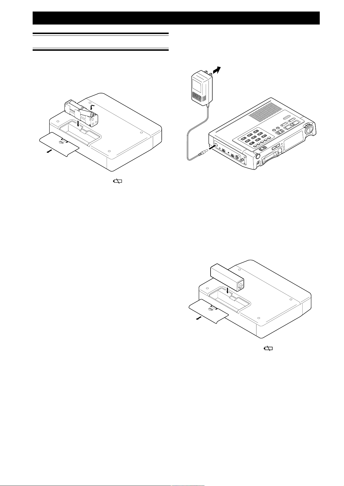
Batteries and AC Adaptor
Alkaline Batteries
The PMD680 uses 8 standard AA-type alkaline batteries.
Load as shown in the following illustration.
SETTING UP
AC adaptor
When recording for extended periods, or using this unit
in a studio environment we recommend using the AC
adaptor.
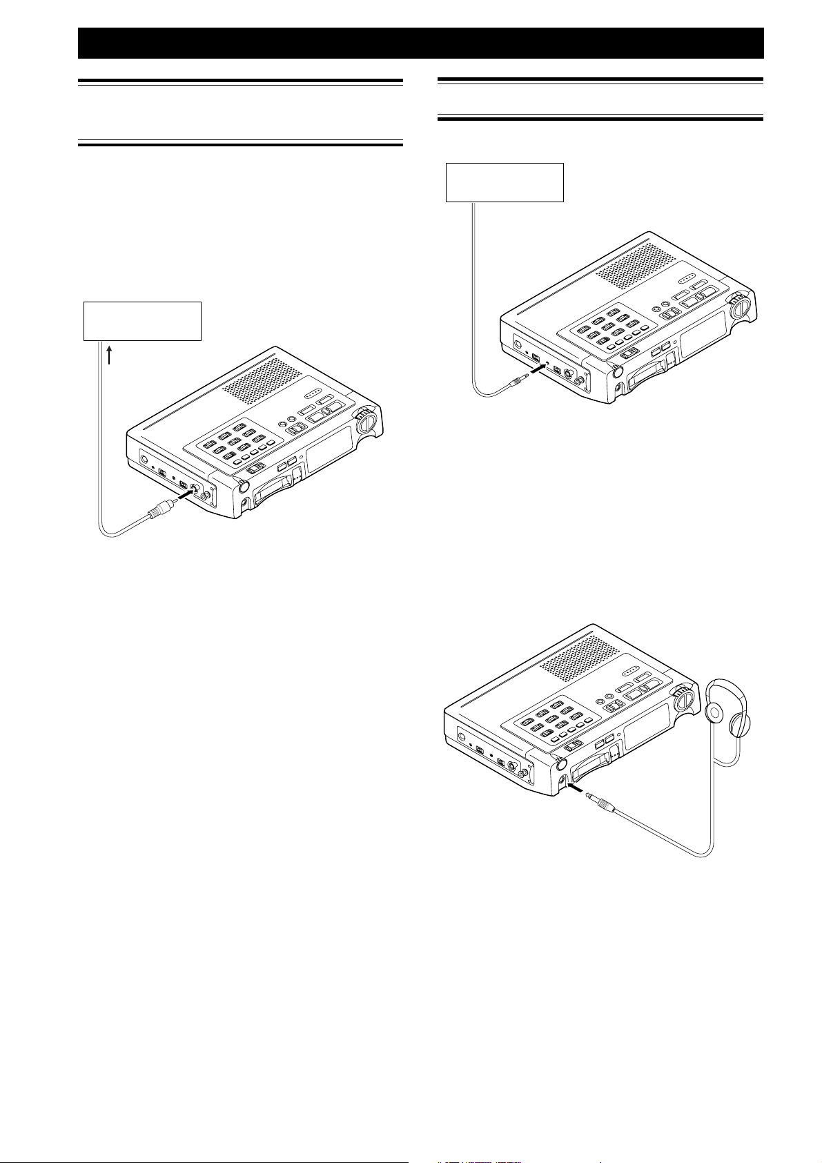
to AC outlet
Battery replacement
When the battery alert indicator ( ) appears in the
display, replace all batteries with new ones. Once this
indicator appears there are approximately XXX hours of
battery life remaining.
Fresh alkaline batteries can provide up to XXX hours of
continuous recording or playback.
Notes
• When recording, to avoid problems caused by loss of
battery power it is recommended to always use new
alkaline batteries.
• Use only AA batteries for replacement.
• Be sure to insert the batteries with correct polarity (as
illustrated on the battery compartment).
• Remove the batteries if the unit will not be used for an
extended period of time.
• Battery life may vary depending on the conditions under
which the unit is operated (environmental temperature,
humidity, speaker usage, etc.).
• If batteries leak, dispose them immediately. Avoid
touching the leaking material or letting it come into
contact with clothing, etc. Clean the battery compartment
thoroughly before installing new batteries.
Notes
• It is recommended to always use a Marantz AC adaptor
(DA740PMDU).
Ni-Cad Rechargeable Battery
(optional)
The PMD680 can use an optional Ni-Cad rechargeable
battery. Be sure batteries are fully charged before use.
These batteries have a longer operating life than
standard alkaline batteries, reducing the number of
battery changes required under heavy usage (see
below). Refer to the following illustrations to load the
battery.
Battery replacement
When the battery alert indicator (
display, charge the battery or replace the rechargeable
battery with a fully charged one. Once this indicator
appears there are approximately (???) hours of battery
life remaining.
Fully charged Ni-Cad batteries can provide up to 3
hours of continuous recording or playback.
Charging time
Approximately 3 hours.
Notes
• When recording, to avoid problems caused by loss of
battery power it is recommend to always use fully charged
batteries.
• Battery life may vary depending on the conditions under
which the unit is operated (environmental temperature,
humidity, speaker usage, etc.).
• It is recommended to only use the Marantz AC adaptor
(DA740PMDU) for charging the rechargeable battery.
) appears in the
3
Page 4
SETTING UP
Power On/Off
Power on
Sliding the power switch rightward makes power on
and off in turn.
When power is applied from the battery or the AC
adapter, sliding the power switch make the unit enter
standby status.
Sliding the power switch rightward in standby status,
the main power is put on and the unit detects existence
of the card in the card slot.
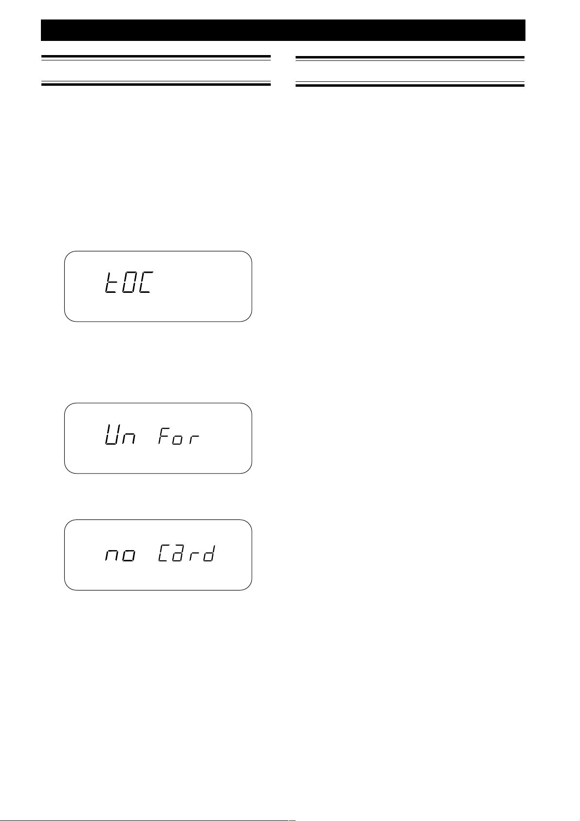
If the card in the slot is formatted complying with the
units specification, the display blinks showing TOC
(Tabel Of Contents) creating message, then enters stop
status.
5
5
5
5
5
5
5
About the display in stop status, please refer to the
chapter of "Data Display" on page xxx.
If the card is not formatted complying with the unit
specification, the display shows unformat message.
5
5
5
5
5
OVER
Setting the Date and Time
Before operating your PMD680, perform the following
operations to set the current date and time.
The current date and time are recorded automatically at
the beginning of each recording.
1 With the power off, slide POWER to the right
while holding down DISPLAY (TIME/DATE).
The unit turns on and enters the date/time
setup mode.
2 Press 1˜4 or ¢˜¡ to set the year, then
press PLAY/PAUSE (3˜8) to enter.
3 Press 1˜4 or ¢˜¡ to set the month,
then press PLAY/PAUSE (3˜8) to enter.
4 Press 1˜4 or ¢˜¡ to set the day, then
press PLAY/PAUSE (3˜8) to enter.
5 Press 1˜4 or ¢˜¡ to set the hour, then
press PLAY/PAUSE (3˜8) to enter.
6 Press 1˜4 or ¢˜¡ to set the minute,
then press PLAY/PAUSE (3˜8) to enter.
7 The seconds start counting from 00 and the
unit automatically returns to its normal
operation mode (stop status) immediately
after you press DISPLAY (TIME/DATE) key.
Pressing PLAY/PAUSE (3˜8) instead of
DISPLAY (TIME/DATE) key, the minute
setting is entered and the menu returns to year
setting menu (step 2).
8 Pressing STOP (7) before setting minute
cancels all the date/time setting.
If the card does not exist in the card slot, the display
shows no card message.
Power Off
Sliding the power switch rightward while main power
is on, the main power is put off after necessary process
for shutdown, and the unit enters standby status.
While recording or rec-pause, the main power is not put
off even if the power switch is operated.
4
Page 5
Understanding PC Cards
The model PMD680 records directly to Flash or Hard
Disk-type PC cards. One of the many advantages is that
it allows you to transfer audio data to a computer
immediately after recording.
Recommended media
SanDisk® PC Card
SanDisk
SanDisk and Compact Flash are trademarks of SanDisk.
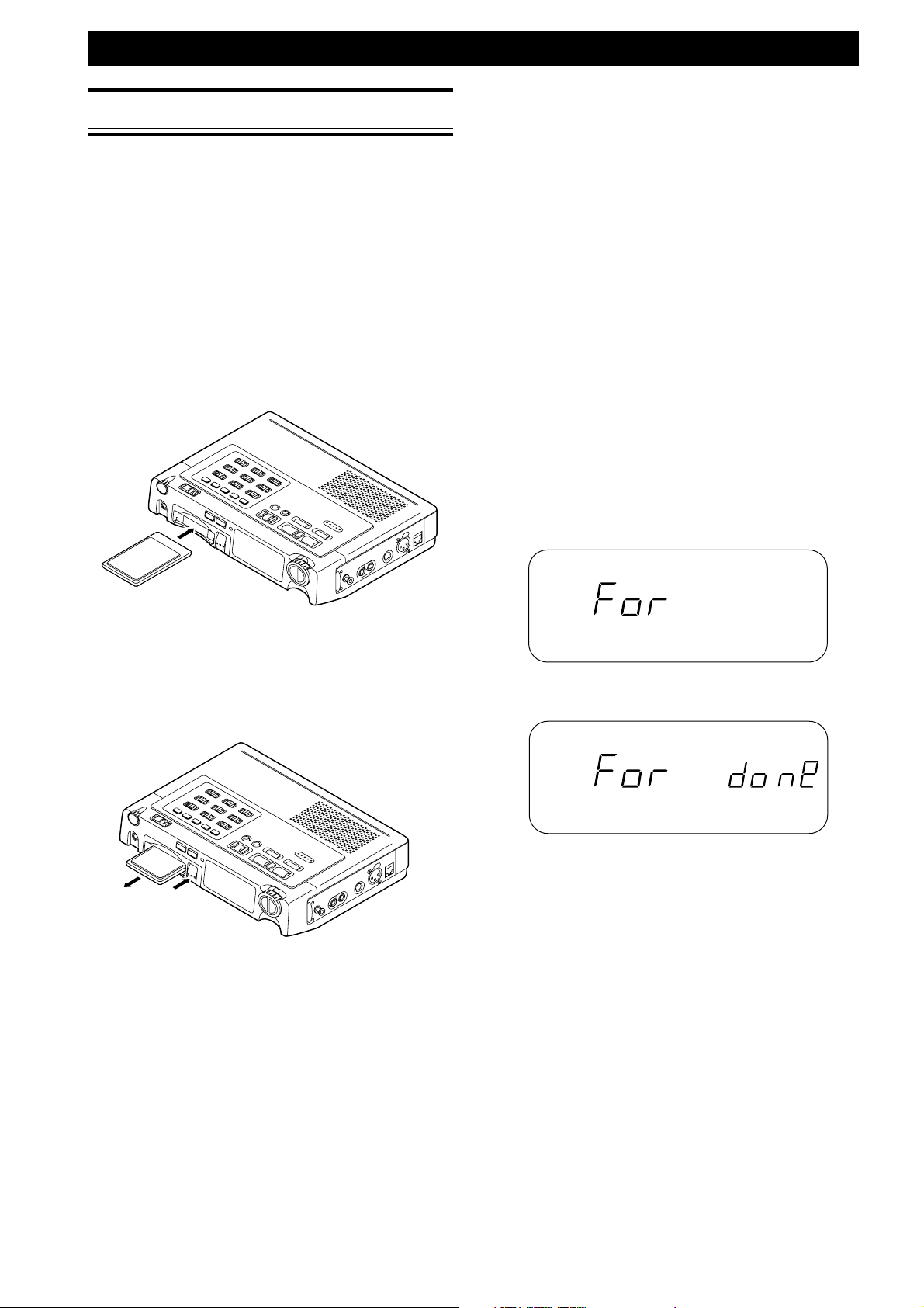
Inserting the card
®
Compact Flash (with PC card adapter)
SETTING UP
Formatting the PC card
Before using a PC Card for the first time, perform the
following operations to format the PC card so that it can
be used to record audio. This operation completely
erases any information stored on the card. Be sure to
backup any important information before formatting.
Note
You can also use this operation to completely erase a
previously used PC card containing audio data you no longer
need.
Operation
1 Start operation in standby mode.
2 Insert card you want to format.
3 Slide the POWER to the right while holding
down ERASE (FORMAT).
4 The format message is displayed.
5 After formatting the card and generate the EDL
file, "done" message is displayed for 3 seconds.
6 The unit enters the stop status.
Notes
• Make sure the card is inserted with the correct side facing
up.
Ejecting the card
PUSH
Note
The EJECT button is mechanical and ejects the PC card
regardless of the unit’s power or operating status.
Do not press EJECT while recording (when the REC indicator
is lit). This may result in the loss of all data on the PC card.
Display while formatting
OVER
Display when the formatting was done (for S seconds)
OVER
Notes
• Even the PC card was formatted by MSDOS PC,
formatting by the unit is neccessary to format it in the
unit's format. After this formatting, the PC card is still
readable by PC as MSDOS file.
After using the card many times, it is recommended to do
this formatting operation to streamline the fragmentation.
• Do not eject the PC card or turn this unit’s power off while
formatting is in progress.
5
Page 6
SETTING UP
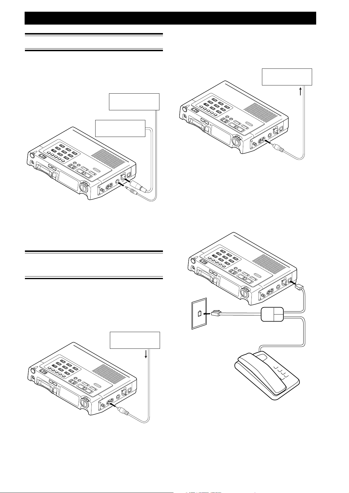
Connecting Microphones
Connect the microphones as shown below.
With the PMD680, you can connect a microphone (for
mono recording) to either the MIC 1 (XLR) jack or the
MIC 2 (1/4" phone) jack.
MIC (1/4")
or
MIC (XLR)
To output analog audio signals to another
audio component
Connect the source component’s analog line input jacks
to this unit’s LINE OUT (RCA) jack.
TAPE DECK, etc.
LINE IN
Notes
• To connect the mono PMD680 LINE OUT to a stereo input,
a Y-adaptor cable can be used.
Notes
• Take care to not connect or disconnect microphones while
recording. This may result in unwanted sounds in the
recording.
Connecting Analog
Components
The following illustrations show you how to connect
analog audio components for recording or playback.
To record from analog audio components
Connect the source component’s analog line output
jacks to this unit’s LINE IN (RCA) jack.
TAPE DECK, etc.
LINE OUT
To record from or output through a telephone
wire
Connect the phone line to the TELEPHONE IN/OUT
jack.
RJ-11 splitter
Wall jack
Notes
• To connect a stereo source to the mono PMD680 LINE IN,
a Y-adaptor cable can be used.
6
Phone
Notes
• Do not start recording until the telephone connects with
the dialed telephone number.
• Please be advised that connecting the PMD680 to a
telephone line is illegal in some countries.
Page 7
SETTING UP
Connecting Digital
Components
The following illustrations show you how to connect
digital audio components for recording.
To output digital audio signals to another audio
component
Connect the source component’s digital input jacks to
this unit’s DIGITAL OUT (coaxial) jack, and set the
DIGITAL OUT switch ON.
DAT, etc.
DIGITAL IN
Other Connections
Remote control
Contact closure
switch
Available Functions
The remote Pauses or Un-Pauses the unit when Play
status.
Notes
• The unit must first be put in Play status manually before
the remote connector will work.
Notes
When digital output is not used, turn the DIGITAL OUT
switch OFF.
Headphones
Connect headphones to the PHONES output to monitor
the sound during recording and playback.
Use the HP/SPK VOLUME knob to control the volume
of the headphones. The sound from the internal speaker
is muted automatically when headphones are
connected.
7
Page 8
GENERAL FUNCTION
Charging Battery
Charging Battery is done while,
• power is supplied from AC adaptor.
• Ni-Cad battery is loaded.
• presetting of battery is Ni-Cad battery (refer to page xxx,
PRESETTING).
• CHARGE slide switch setting is ON
While charging, charge LED blinks. After charge is
completed, charge LED becomes stably on.
Note
• Charge does not happen and charge LED turns off while
power is on. Charge occurs only in standby (power off)
status.
Low Battery Warning and
Auto Power Off
When the remaining battery energy is anticipated to last
in about xxx minutes, battery warning indicator turns
on in the display (1st warning).
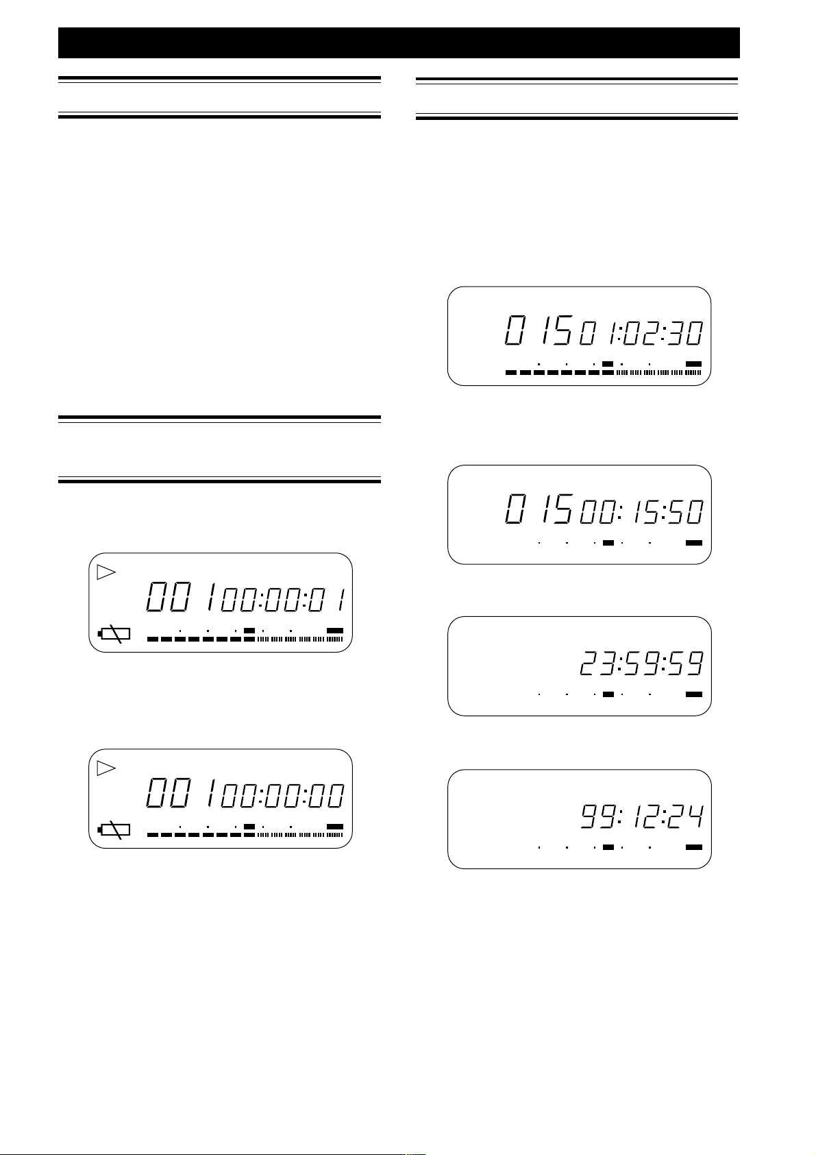
Data Display
Changing Display Information
Pressing DISPLAY (TIME/DATE) key changes the
display information as follows.
During stop mode
q Total Track No Total Track Time
TRACK
SP
50 40 24 6 2 0∞
-dB
w Total Track No Remain Time
(time available for recording
at the selected bit rate)
TRACK
SP
50 40 24 6 2 0∞
-dB
TOTAL TIME
12
REMAIN TIME
12
OVER
OVER
TRACK
50 40 24 6 2 0∞
-dB
12
TIME
OVER
After that, when the remaining battery energy is
anticipated to last soon, battery warning indicator in the
display and REC LED start to blink, and beep sound
turns on and off in 1 second interval (2nd warning).
5
5
5
5
5
5
5
-dB
5
TRACK
50 40 24 6 2 0∞
12
TIME
OVER
After 2nd warning, when the battery voltage goes down
lower than operating voltage, the unit enters auto
power off process. If the unit is working (playback,
recording, editing), necessary shut down process (file
update and closing) takes place. Then the power is
turned off and the unit enters standby status.
e Current Time
SP
-dB
r Current Date
SP
-dB
TIME
50 40 24 6 2 0∞
50 40 24 6 2 0∞
12
12
OVER
TIME
OVER
8
Page 9
GENERAL FUNCTION
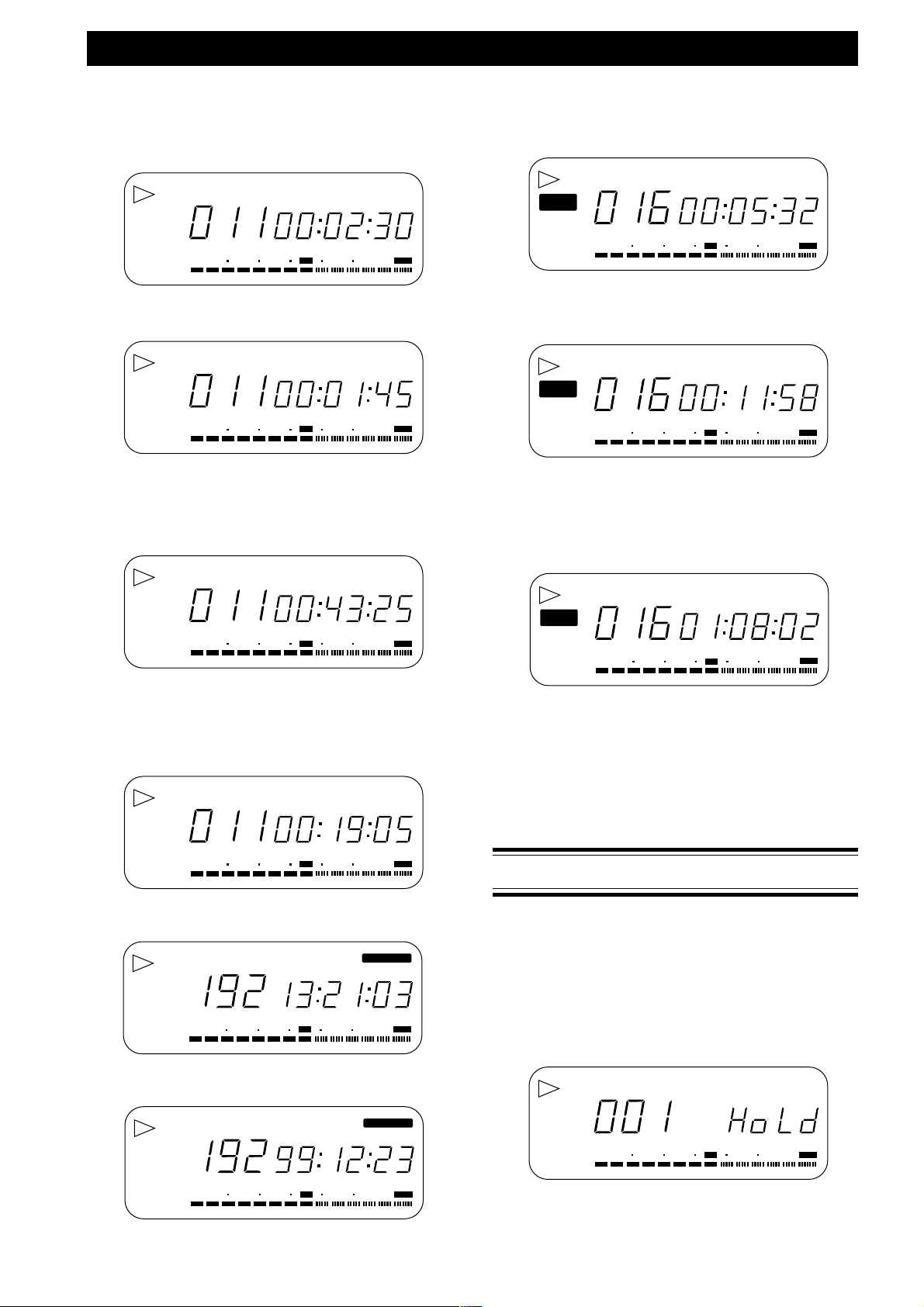
During playback
q Current Track No Time elapsed on current
playing track
TRACK
SP
50 40 24 6 2 0∞
-dB
12
w Current Track No Remain time of current
playing track
TRACK
SP
50 40 24 6 2 0∞
-dB
12
e Current Track No Accumulated time elapsed
(Total time of exiting tracks
previous to the current track
+ time elapsed on current
playing track)
SP
TRACK
50 40 24 6 2 0∞
-dB
TOTAL TIME
12
TIME
OVER
REMAIN TIME
OVER
OVER
During Recording
q Current Track No Recording elapsed time on
REC
SP
50 40 24 6 2 0∞
-dB
w Current Track No Remain recording time
REC
SP
50 40 24 6 2 0∞
-dB
e Current Track No Accumulated recording time
REC
SP
50 40 24 6 2 0∞
-dB
current track
TRACK
12
(Time available for
recording)
TRACK
12
REMAIN TIME
elapsed
(Total time of exiting tracks
previous to the current track
+ recording time elapsed on
the current track)
TRACK
TOTAL TIME
12
TIME
OVER
OVER
OVER
r Current Track No Total playback remain time
(Total time of exiting tracks
after the current track +
Remain time of current
playing track)
SP
TRACK
50 40 24 6 2 0∞
-dB
TOTAL REMAIN TIME
12
OVER
t Recorded Bit Rate Time when the current track
recording was started
RECORDED
TIME
SP
50 40 24 6 2 0∞
-dB
12
OVER
y Recorded Bit Rate Date when the current track
recording was started
RECORDED
To Illuminate the Display Panel
• Pressing LIGHT key for less than 1 second, the back
light of the display panel turns on for 3 seconds and
turns off.
• Pressing the LIGHT key for 1 second or more, the
back light turns on and keeps on. Pressing the LIGHT
key again, the back light turns off.
Keylock
To avoid accident by unintentionally hitting the key,
keylock function is provided.
While the KEYLOCK slide switch is set to LOCK
position, any other key operation is neglected except
that;
LIGHT key while power on status.
POWER key while power off (standby) status.
If you operate the other keys, "Hold" message is
displayed for 1 second.
TRACK
SP
50 40 24 6 2 0∞
-dB
50 40 24 6 2 0∞
-dB
12
OVER
Note
Keylock effects on PRE REC (slide switch), REC MODE (slide
12
OVER
switch), and all push buttons except LIGHT key.
Keylock does not effect on other slide switches.
9
Page 10
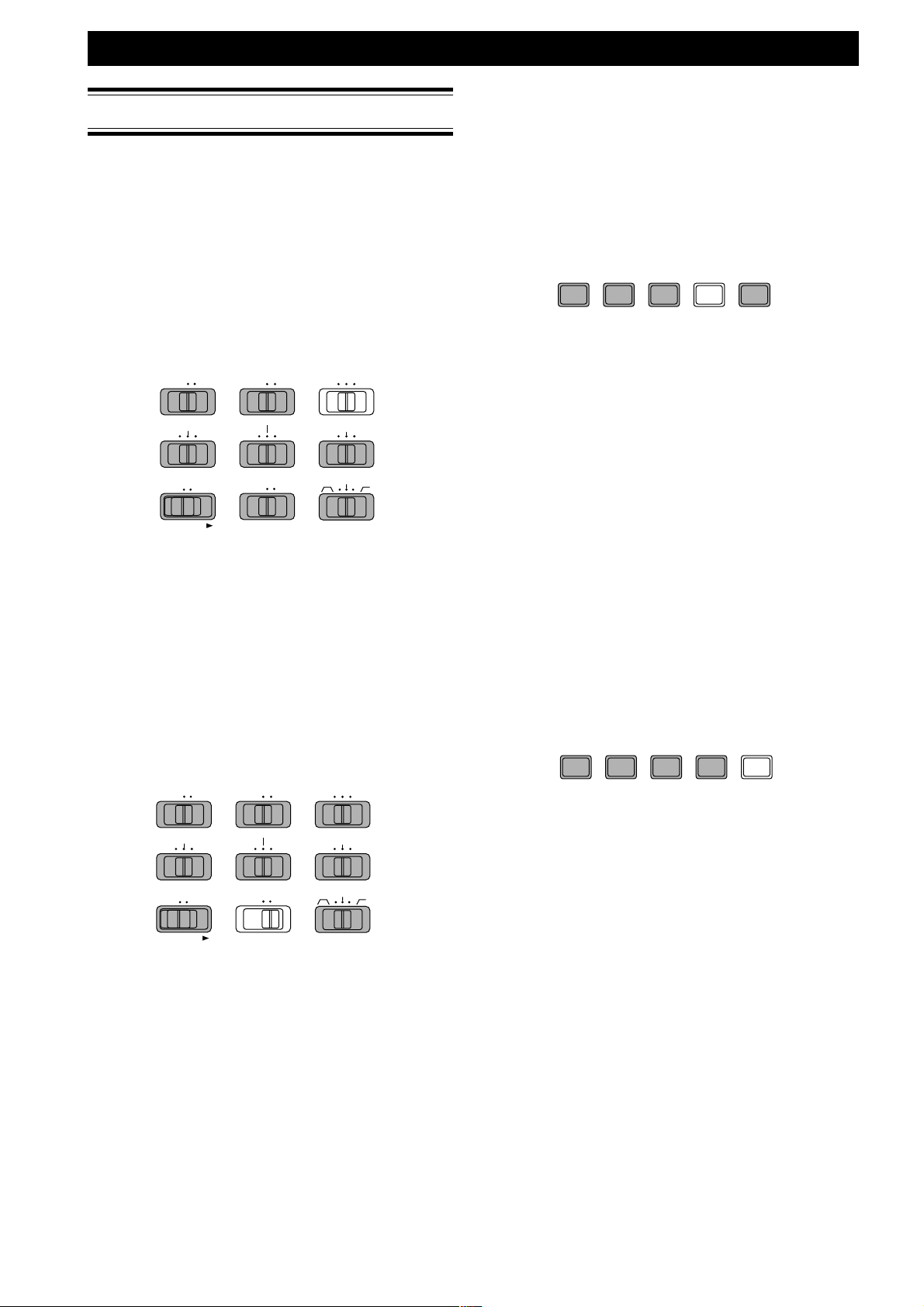
RECORDING
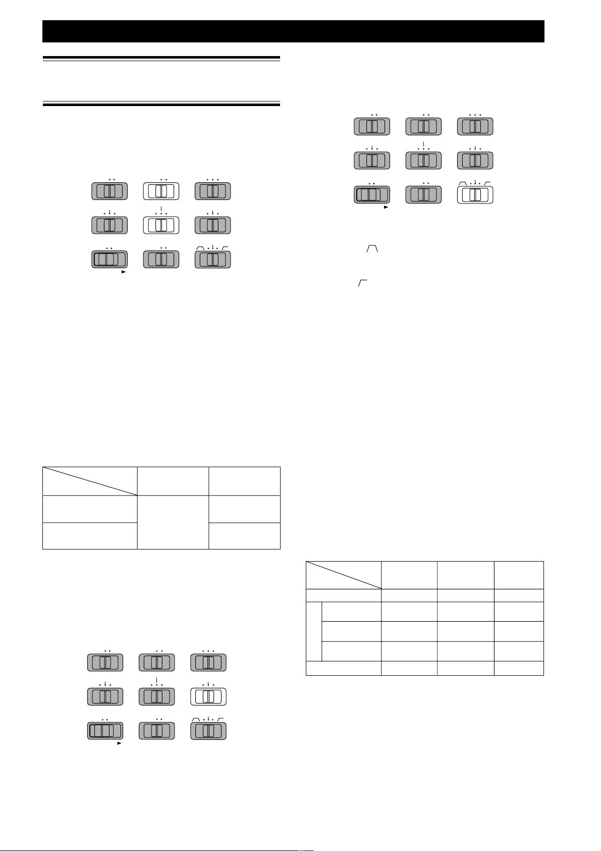
Selection and Manipulation
of Input Source
Input Source Selection
Input source is selected from external XLR microphone
connector input, 1/4" microphone connector input,
internal microphone input, line input, and telephone
input.
OFF
ON 1
2/INT SP LP
MP
Ambient Noise Control
ANC (Ambient Noise Control) is effective for all
microphone input and telephone input, but is not
effective for line input.
ON 1
OFF
SPEAKER
LIMITER
ALC
MANUAL
REC LEVEL
LOCKOFF
2/INT
MIC
TEL LINE
INPUT
OFF ON
SP LP
REC MODE
-15dB
0dB
MIC ATTEN
FLAT
MP
-30dB
SPEAKER
LIMITER
ALC
REC LEVEL
KEY LOCK
MANUAL
LOCKOFF
MIC
TEL LINE
INPUT
OFF ON
PRE REC
REC MODE
-15dB
0dB
MIC ATTEN
FLAT
ANC
-30dB
INPUT LEVEL switch selects from telephone input,
microphone input, and line input. Only when INPUT
LEVEL switch is at the MIC INPUT position, MIC
INPUT switch becomes effective. XLR microphone
connector input is assigned to "1" position of MIC
INPUT switch. 1/4" microphone connector input and
internal microphone input are assigned to "2 / INT
MIC" position of MIC INPUT switch.
If a microphone plug is inserted into the 1/4"
microphone connector, the input from the 1/4"
microphone connector becomes effective. If a
microphone plug is not inserted into the 1/4"
microphone connector, the input from the internal
microphone becomes effective.
Effective microphone input
MIC INPUT
1/4" connector
Inserted
Not inserted
switch position
1 2 / INT MIC
XLR microphone
connector input
1/4" microphone
connector input
Internal Microphone
Input
KEY LOCK
PRE REC
ANC
This function filters out unwanted frequencies for
recording.
• Band-pass (
) : Cuts low frequency (150Hz and
lower) and high frequency (3KHz and higher)
• Flat : No filtering
• Low-cut (
) : Cuts low frequency (150Hz and
lower)
REC LEVEL
For all inputs (external microphone, internal
microphone, line), three ways of level control are
selected by REC LEVEL switch
• ALC (Automatic Level Control): Automated recording
level adjustment based on the level of the input signal
(REC LEVEL knob does not effect the recording).
Time constant is long to prevent sudden fluctuations
in the recording level.
• LIMITER: Although the recording level must be
adjusted by REC LEVEL knob, signals over 0VU
trigger an automatic reduction of the recording level.
Time constant is short to provide quick restoration of
the manually set recording level.
When limitter works (at signals over 0VU), REC LED
also dimms as a noticeable warning.
(Refer to Recording Indication on page xx)
• MANUAL: Recording level must be adjusted
manually using the REC LEVEL knob.
Effective Manipulation for Inputs
MIC ATTENUATION
MIC ATTENUATION is effective only for the signal
from external microphone inputs, i.e. XLR microphone
connector input and 1/4" microphone connector input.
MIC ATTENUATION is NOT effective for the signal
from internal microphone inputs and line input.
OFF
SPEAKER
LIMITER
ALC
REC LEVEL
KEY LOCK
ON 1
MANUAL
LOCKOFF
2/INT
MIC
TEL LINE
INPUT
OFF ON
PRE REC
MP
SP LP
REC MODE
-15dB
0dB
MIC ATTEN
FLAT
ANC
-30dB
0dB (no attenuation), -15dB attenuation, and -30dB
attenuation of the microphone input is selected by MIC
ATTENUATION switch. Mic attenuation is used to
normalize the difference in sensitivity of the external
microphones and realize the best S/N ratio in recording.
10
Manipulation
Input
Telephone Input
XLR microphone
connector input
1/4" microphone
MIC
connector input
Internal
microphone Input
Line Input
MIC ANC REC LEVEL
ATTENUATION
Not effective Not effective Effective
Effective Effective Effective
Effective Effective Effective
Not effective Effective Effective
Not effective Not effective Effective
(Ambieent Noise
Control) MANUAL)
(ALC, LIMITTER,
Recording Level Adjustment
For the input on which REC LEVEL is effective (refer to
the above table), recording level should be adjusted
using LEVEL KNOB. Watching the audio level meter
and monitoring the input sound, use the REC LEVEL
knob to adjust the audio level meter so that the 0dB
indicator just barely flicker at the highest peak of the
input sound level. The OVER indicator should not light
(this would result in clipping).
Page 11
Recording Behavior Setting
REC MODE
Three recording modes are selectable
• LP (Long Play mode): Long playback/recording time,
Low sound quality. (Icon LP is showed on the display
during recording status and rec-pause status.)
• MP (Medium Play Mode): Medium playback
recording time, Medium sound quality. (Icon LP and
SP turn off on the display during recording status and
rec-pause status.)
• SP (Short Play mode) Short playback/recording time,
High sound quality. (Icon SP is showed on the display
during recording status and rec-pause status.)
OFF
SPEAKER
LIMITER
ALC
REC LEVEL
ON 1
MANUAL
TEL LINE
LOCKOFF
2/INT
MIC
INPUT
OFF ON
MP
SP LP
REC MODE
-15dB
0dB
MIC ATTEN
FLAT
-30dB
RECORDING
SILENT SKIP
After detecting continuous certain length of silence, the
unit enters rec-pause status and stays in that status as
long as silence continues. When sound input is detected,
the unit resumes recording. This function saves the card
memory by skipping the silent part.
Silent skip mode is set and reset in toggle manner by
pushing the SILENT SKIP button. While silent skip
mode is set, the icon S.SKIP turns on in the display.
REPEAT RENUMBER ERASE SILENT SKIP AUTO MARK
FORMAT PRESET
The level and the length of sound to enter the rec-pause
status are preset by preset operation (refer to Presetting
Parameters on page xx). The factory setting (default)
value is three seconds, -40 dB.
The sound level to resume recording is always -24dB.
SILENT SKIP always works with pre-recording function
(PRE-REC) regardless of PRE-REC switch setting, to
prevent dropping of recorded sound when the
recording is resumed.
KEY LOCK
PRE REC
ANC
The bit rate is assigned to each recording mode by
preset operation (Refer to the chapter of Presetting
Parameters on page xx).
PRE REC
While PRE REC switch is on, pre-recording function
becomes active. While REC PAUSE status, 2 seconds
sound data is recorded in a buffer memory in the unit in
first-in-first-out manner.
So, 2 seconds of recording is added prior to the
recording made after the recording operation is started.
This function saves from missing the unexpected
recording chance which occurs suddenly.
OFF
SPEAKER
LIMITER
ALC
REC LEVEL
KEY LOCK
ON 1
MANUAL
LOCKOFF
2/INT
MIC
TEL LINE
INPUT
OFF ON
PRE REC
Note
• If REC PAUSE status was less than 2 seconds, the sound
during REC PAUSE is pre-recorded.
• When pre-recording is started, recording elapsed time
shown in the display starts counting up. If the prerecording status exceeds 2 seconds, the recording elapsed
time in the display keeps blinking showing 2 seconds.
• When recording is started, pre-recorded time (2 seconds in
maximum) is added to the time after recording is started,
and so displayed.
• If STOP is pressed while REC PUASE status, prerecorded
data is lost and the unit enters STOP status.
MP
SP LP
REC MODE
-15dB
0dB
MIC ATTEN
FLAT
ANC
-30dB
Note
Silent skip works while recording status. So, once you
have to start recording.
In rec-pause status made manually (by pressing REC/
MARK button once in stop status, or by pressing PLAY/
PAUSE button while recording), the recording does not
start even if the sound is detected.
AUTO MARK
A mark is put automatically every time rec-pause status
changes to REC status.
REPEAT RENUMBER ERASE SILENT SKIP AUTO MARK
FORMAT PRESET
AUTO MARK mode is set and reset in toggle manner by
pushing the AUTO MARK button. While AUTO MARK
mode is set, the icon A. MARK turns on in the display.
While silent skip (S.SKIP) mode is set, the unit
automatically put a mark when the recording is
resumed at the sound detected after the silence.
For mark, refer to "Marking and EDL Playback" on page
xxx.
Note
• AUTO MARK mode can be set/reset whether in recording
status or in rec-pause status.
• Maximum quantity of mark in a card is 255. If the quantity
of the mark is already 255, the unit does not enter the
AUTO MARK mode even pushing the AUTO MARK
button.
• When the the unit enters rec-pause status with the 255
marks, AUTO MARK mode is reset and shows mark full
message "FULL -P 255" in 3 seconds, staying in recording
standby (rec-pause) status. Recording function other than
AUTO MARK works normally.
11
Page 12

RECORDING
Recording Operation
Basic Procedure
• Pressing REC/MARK key in stop status, the unit
enters rec-pause status.
• Pressing REC/MARK key in rec-pause status, the unit
enters recording status.
• Pressing PLAY/PAUSE key in recording status, the
unit enters rec-pause status.
• Pressing REC/MARK key in recording status, the unit
put mark at that point (regarding mark, refer to
Marking and EDL playback on page xx).
• Pressing STOP key in recording status or in rec-pause
status, the unit enters stop status.
record settings
REC LED
REC/MARK
STOP
Track Number of New Recording
Track number of new recording is next number to that
of the last track. If number of the last track is N, the
track number of new recording is N+1.
Card full
When card becomes full while recording, the recording
is stopped, the card full message "FUL Card" is
displayed for 3 seconds.
This message is also displayed when attempt to start
recording was made (REC/MARK button was pressed)
after card full. Then the unit stops.
Track Full
The maximum track number in a card is 255 tracks.
When attempt to start recording was made (REC/
MARK button was pressed) while 255 tracks exits
already in a card, track full message "FUL 255" is
displayed.
Sound Level Monitoring
In rec-pause status and in recording status, the input
sound becomes audible (through the internal speaker or
head phone) and sound level is displayed at the level
meter.
Recording Indication
During rec-pause status, REC indicator on the display
and REC LED on the front panel blink.
During recording status, REC indicator on the display
and REC LED on the front panel turn on.
REC
SP LP
TRACK
50 40 24 6 2 0
∞
-dB
12
TIME
OVER
REC LED dimms when the limitter works.
(Refer to REC LEVEL on page xx)
Caution
Changing REC MODE switch during recording or recpause is not effective. The change is effective only in
stop status and the REC MODE is applied to the next
track recording.
The minimum length of one track is 0.5 second. A track
less than 0.5 second is not generated (If you start
recording and stop it after less 0.5 second, a track would
not be made).
12
Page 13

Basic Operation
Playback can be monitored through the internal speaker
or a pair of headphones. Use the HP/SPK VOLUME
knob to adjust the level of the internal speaker or
headphones.
The audio signal is also output from the LINE OUT jack,
DIGITAL OUT jack, and TELEPHONE IN/OUT jack.
The level of the signals output from these jacks is not
effected by the position of the HP/SPK VOLUME knob.
Preparation
PLAYBACK and EDITING
Stop
To stop playback, press STOP ( 7 ).
If mark was edited during the playback, EDL file is
updated. During EDL update, display shows "TOC"
blinking (about EDL, refer to Marking and EDL
Playback on page xx).
5
5
5
5
5
5
5
5
5
5
5
5
OVER
SPEAKER MODE / SPEAKER
To listen to the playback via the internal speaker, set the
SPEAKER switch to ON. To mute output from the
internal speaker (when using an external monitor
system, etc.) set SPEAKER to OFF.
Note
When headphones are connected no sound comes from the
internal speaker, regardless of the setting of the SPEAKER
switch.
Operation
To start playback
Press PLAY/PAUSE (3˜8) during stop mode.
To pause during playback
Press PLAY/PAUSE (3˜8).
The playback is paused at the location when PLAY/
PAUSE is pressed.
To switch the information shown in the display
Press TIME (refer to Data Display on page XX).
When STOP key is pressed, playback location returns to
the beginning of the first track.
13
Page 14

PLAYBACK and EDITING
Audible Seek
This section explains about higher speed (x4) audible
access.
(refer to Summary of Accessing Behavior on page xxx
for the details)
+
Seek
Seek + is 4 times fast audible forward access.
Press and hold ¢/¡ during playback.
The unit playbacks forward at four times as high speed
as normal playback speed.
Holding the ¢/¡ presssed.
The unit keeps going the Seek
¢/¡, the unit resumes playback at the normal
speed. Playback time counter is displayed according to
the Seek
Note
While keeping on Seek + , the unit works as follows according
to repeat play mode (refer to Repeat Play on page xxx):
• If single track repeat mode is not set, Seek + goes through
• If single track repeat mode is set, Seek + works within the
Seek
+
motion.
the tracks util the end of the last track. Then;
• If entire track repeat mode is not set, the unit stays at
the end of the last track without sound.
• If entire track repeat mode is set, the unit skips to the
top of the first track and continues Seek +. (When entire
track repeat mode is on, whole tracks are assumed to be
continuous in a circle manner in Seek +, that is, next
track to the last track is assumed as the first track.)
current track only.
• When the unit reached the end of the track, the unit
skips to the top of the current track and continues Seek +.
-
Seek - is 4 times fast audible backward access.
Press and hold 1/4 during playback.
The unit playbacks backward at four times as high
speed as normal playback speed.
Holding the 1/4 pressed, the unit keeps going the
-
Seek
. Then releasing the 1/4, the unit resumes
playback at the normal speed. Playback time counter is
displayed according to the Seek
Note
While keeping on Seek -, the unit works as follows according to
repeat play mode (refer to Repeat Play on page xxx):
• If single track repeat mode is not set, Seek - goes through
the tracks util the top of the first track. Then stays there
without sound until the 1/4 is released. After
releasing 1/4, the unit resumes playback from there
at the normal speed.
• If single track repeat mode is set, Seek - works within the
current track only.
• When the unit reached top of the current track, the unit
stays there without sound until 1/4 is released.
After releasing 1/4 , the unit resumes playback
from there at the normal speed.
+
. Then releasing the
-
motion.
Un-audible Fast Access
This section explains about 30-250 times fast un-audible
access.
(refer to Summary of Accessing Behavior on page xxx
for the details)
FF (Fast Forward)
FF is 30-250 times fast un-audible forward access.
Press and hold ¢/¡ during pause status.
The unit runs forward without sound at thirty times as
fast as normal playback speed.
After keeping ¢/¡ pressed for 2 seconds, the FF
speed shifts up to 250 times as fast as normal playback
speed.
Keeping ¢/¡ pressed, the unit keeps FF .
Playback time counter is incremented and displayed
according to the FF motion.
Releasing ¢/¡, the unit pauses at the location
shown by the time counter.
Note
While keeping on FF, the unit works as follows according to
repeat play mode (refer to Repeat Play on page xxx):
• If single track repeat mode is not set, FF goes through the
tracks util the end of the last track. Then;
• If entire track repeat mode is not set, the unit pauses at
the end of the last track.
• If entire track repeat mode is set, the unit skips to the
top of the first track and continues FF. (When entire
track repeat mode is on, whole tracks are assumed to be
continuous in a circle manner in FF as well as in Seek+.
That is, next track to the last track is assumed as the first
track.)
• If single track repeat mode is set, FF works within the
current track only.
• When the unit reached the end of the track, the unit
skips to the top of the current track and continues FF.
RWD (ReWinD)
RWD is 30 times fast un-audible backward access.
Press and hold 1/4 during pause status.
The unit playbacks backward at thirty times as high
speed as normal playback speed.
After keeping 1/4 pressed for 2 seconds, the RWD
speed shifts up to 250 times as fast as normal playback
speed.
Keeping 1/4 pressed, the unit keeps RWD.
Playback time counter is decreased and displayed
according to the RWD motion.
Releasing 1/4, the unit pauses at the location
shown by the time counter.
Note
While keeping on RWD, the unit works as follows in relation
with repeat play mode (refer to Repeat Play on page xxx):
• If single track repeat mode is not set, RWD goes through
the tracks util the top of the first track, and pauses there.
• If single track repeat mode is set, RWD works within the
current track only.
• When the unit reached top of the current track, the unit
pauses there.
14
Page 15

PLAYBACK and EDITING
Track Jump
This section explains about track jump, which enables to
access to the top of the destination track.
(refer to Summary of Accessing Behavior on page xxx
for the details)
Next Track Jump
• Tap (press and release in an instant) ¢/¡ during
playback.
The playback location jumps to the top of the next
track and the unit starts playback. The incremented
track number is displayed.
• Tap ¢/¡ during pause.
The playback location jumps to the top of the next
track and the unit pauses there. The incremented track
number and pause icon (38) are displayed.
Note
If next track jump occurred in the last track, the playback
location jumps to the top of the 1st track.
Previous Track Jump
• Tap 1/4 during playback.
• If elapsed time from the top of the track is 1 second
or less, playback location jumps to the top of the
previous track and the unit starts playback from
there. The decreased track number is displayed.
• If elapsed time from the top of the track is more
than 1 second, playback location jumps to the top of
the current track and the unit starts playback from
there.
• Tap 1/4 during pause.
• If elapsed time from the top of the track is 1 second
or less, playback location jumps to the top of the
previous track and the unit pauses there. The
decreased track number and pause icon (8) are
displayed.
• If elapsed time from the top of the track is more
than 1 second, playback location jumps to the top of
the current track and the unit pauses there. The
decreased track number and pause icon (38) are
displayed.
Track Count Up/Down
Starting from stop status, track count up/down enables
quick track select.
(refer to Summary of Accessing Behavior on page xxx
for the details)
Track Count Up
• Tap ¢/¡ during stop.
The playback location jumps to the top of the next
track and stays there.
The incremented track number is displayed. Pause
icon (38) is not displayed.
• Press and hold ¢/¡ during stop.
The track number counts up quickly (4 track/sec).
After keeping ¢/¡ pressed for 2 seconds, count
up speed doubles (8 track/sec). Releasing ¢/¡,
playback location stays at the top of the track which
track number is shown in the display.
The increased track number is displayed.
Track Count Down
• Tap 1/4 during stop.
The playback location jumps to the top of the previous
track and stays there. The decreased track number is
displayed.
• Press and hold 1/4 during stop.
The track number counts down quickly (4 track/sec).
After keeping 1/4 pressed for 2 seconds, count
down speed doubles (8 track/sec). Releasing 1/
4, playback location stays at the top of the track
which track number is shown in the display.
The decreased track number is displayed.
Note
In track count up/down, it is assumed that the first track and
the last track is next track each other.
Thus, track count up occurred at the last track causes jump to
the first track. Similarly, track count down occurred at the first
track causes jump to the last track (regardless of repeat mode
setting).
Note
Previous track jump occurred before 1 second track time of the
1st track results in track jump to the top of last track.
15
Page 16

PLAYBACK and EDITING
Repeat Play
You can have the unit repeatedly play a single track or
the full card.
Or, you can specify repeat points anywhere in the tracks
(refer to page xxx, EDL play)
REPEAT
PLAY / PAUSE
(6)
1 / 4 ¢ / ¡
Repeating a Track
1 Use 1˜4 or ¢˜¡ to select the track
you want to repeat.
2 Press PLAY/PAUSE (3˜8) to start playback.
3 Tap REPEAT repeatedly until "REPEAT 1"
appears in the display.
REPEAT 1
SP LP
TRACK
50 40 24 6 2 0
∞
-dB
12
TIME
OVER
To cancel
Press REPEAT repeatedly until "REPEAT" and "REPEAT
1" disappear from the display.
Repeating the Entire card
Press REPEAT repeatedly until "REPEAT" appears
in the display.
REPEAT 1
TRACK
50 40 24 6 2 0
∞
-dB
12
To cancel
Press REPEAT repeatedly until "REPEAT" and "REPEAT
1" disappears from the display.
TIME
OVER
16
Page 17

Summary of Accessing Behavior
PLAYBACK and EDITING
Key Operation
Tap
¢/¡
Press
and
Hold
Tap
1/4
Press
and
Hold
Status when
key is hit
Play
Pause
Stop
Play
Pause
Stop
Play
at track time ≤
1 sec
Play
at track time >
1 sec
Pause
at track time ≤
1 sec
Pause
at track time >
1 sec
Stop
Play
Action during
holding the key
pressed
_
_
_
+
Seek
x4
audible
FF
x30 - x250
un-audible
Track Count Up
Quick Track
Count Up
_
_
_
_
-
Seek
x4
audible
Action after the key
is released
Repeat Mode On
Entire Card
Repeat
Next Track Jump
Playback from the
The next track to the last track is the 1
top of the next track
Next Track Jump
Pause at the top of
the next track
Next Track Jump
Stop at the top of the
next track
Playback from the
location where the
key is released
Pause at the location
End of the last
track continues
to the top of the
st
1
track
where the key is
released
Stop at the top of the
track indicated by the
The next track to the last track is the 1
track counter
Previous Track Jump
Previous track to the 1
Playback from the top
of the previous track
Previous Track Jump
Playback from the top of the current track
Previous Track Jump
Previous track to the 1
Pause at the top of
the previous track
Previous Track Jump
Pause at the top of the current track
Previous Track Jump
Stop at the top of the
The previous track to the 1
previous track
Playback from the location where the
key is released.
When the top of the 1
st
track is reached,
pause there while key is held pressed,
and resume playback after releasing the
key.
Behavior in Repeat Mode
Repeat mode Off
Single Track
Repeat
st
End of the
current track
continues to
At the end of the
last track, the unit
enters stop status.
the top of the
current track
st
st
track* is the last track
st
track* is the last track
st
track is the last track*
When the top of
the current track
is reached,
pause there
while key is held
pressed, and
resume playback
after releasing
When the top of the
1st track is
reached, pause
there while key is
held pressed, and
resume playback
after releasing the
key.
the key.
track*
track*
Pause
Stop
RWD
x30 - x250
un-audible
Track Count Down
Quick Track
Count Down
Pause at the
location where the
key is released
Stop at the top of the
track indicated by the
track counter
When the top of the
1st track is
reached, pause
there.
When the top of
the current
is reached,
pause there.
The previous track to the 1
st
When the top of the
1
st
track
track is reached,
pause there.
track is the last track*
* The track number of the 1st track is not always track number 1. For example, if the 1st track is deleted,
the 1st track may be track number 2. After renumbering operation, the first track will be track number 1.
17
Page 18

PLAYBACK and EDITING
Marking and EDL Playback
Marking Operation
Pushing REC/MARK key during playback, playback
pause, and recording, a mark is placed at the location
where REC/MARK key is pressed.
Putting mark helps access to the marked location, and
further, in EDL Playback mode, the marks can be used
to specify the skip start point, skip destination, and
repeat points.
MARK SELECTERASE
REPEAT
JUMP TO MARK
1 / 4 ¢ / ¡
AUTO MARK
AUTO MARK mode automatically places a mark when
recording starts from rec-pause status.
In silent skip recording mode as well, a mark is placed
every time when recording is resumed detecting sound
from the rec-pause status made by silence.
The total quantity of mark is displayed for one second
istead of track number (TRACK icon turns off). After
one second, the display resumes track number display
(TRACK icon turns on).
Pressing AUTO MARK key turns on and off AUTO
MARK mode. When auto marking mode is on,
"A.MARK" icon is displayed.
TRACK
REC
A.MARK
TIME
PLAY / PAUSE
(6)
STOP (7)REC / MARK
Every time a mark is placed, the total quantity of mark
is displayed for one second instead of track number
(TRACK icon turns off). Then, the display resumes track
number display (TRACK icon turns on).
TIME
50 40 24 6 2 0∞
-dB
12
OVER
When a mark is placed, the total
quantity of mark is displayed
(total quantity of mark = 192)
TRACK
50 40 24 6 2 0∞
-dB
12
TIME
OVER
After one second, the display
resumes track number display
(track number = 124)
Note
• The marked location data is stored in the EDL file in
the card.
• The updated marked location data is written in the
EDL file when the units enters STOP status.
• The mark placed by pressing REC/MARK key is not
yet assigned attributes (Skip, -a,-b) for EDL Playback.
• The maximum number of mark placed in a card is 255.
Attempt to place a mark while already 255 marks
were placed, mark full message, "FUL -p 255", is
displayed for 3 seconds. The mark is not put any more.
50 40 24 6 2 0∞
-dB
12
OVER
For operation to set Auto Mark mode, refer to
"Recording Behavior Setting" on page xxx.
Note
Since the maximum number of marks in a card is 255,
when rec-pause occurs after 255 marks were placed by
auto marking, auto marking mode is automatically
removed. "A.MARK" icon turns off, and mark full
message "FUL –p 255" is displayed for 3 seconds.
Silent skip works after this as well, but a mark would
not be put anymore.
Displayed for 3 seconds
REC
TRACK
50 40 24 6 2 0∞
-dB
TOTAL TIME
12
OVER
A.MARK indicator turned off.
18
Page 19

PLAYBACK and EDITING
Point Skip –a –b
Access to the Mark
Forward Mark Access
In stop status, pressing ¢/¡ key while pressing
JUMP TO MARK key makes the location jump to the
nearest next mark and the unit pauses there.
Then, every time pressing ¢/¡ key while pressing
JUMP TO MARK key, location jumps to next mark point
and pauses there. Pressing PLAY/PAUSE while
pausing, the unit starts playback from there.
Forward mark access from the last mark in a card result
in access to the first mark in the card.
After track count up/down (see page xxx), the forward
mark access makes jump to the mark next to the top of
the selected track.
Backward Mark Access
In stop status, pressing 1/4 key while pressing
JUMP TO MARK key makes the location jump to the
nearest previous mark and the unit pauses there.
Then, every time pressing 1/4 key while pressing
JUMP TO MARK key, location jumps to previous mark
and pauses there. Pressing PLAY/PAUSE while
pausing, the unit starts playback from there.
Backward mark access from the first mark in a card
results in access to the last mark in the card.
After track count up/down (see page xxx), the
backward mark access makes jump to top of the selected
track.
Defining Mark
While pausing at the mark point after mark access
(Jump To Mark) operation, press MARK SELECT key.
Every time MARK SELECT key is pressed, the display
shows definition cyclically.
Showing one of above definitions you want on the
display, press PLAY/PAUSE key. Then the mark is so
defined.
Display while mark definition
50 40 24 6 2 0∞
-dB
12
OVER
Display at Mark Access
When the mark is accessed by forward mark access or
backward mark access, the mark number accessed
(sequential number) is displayed for one second instead
of track (TRACK icon turns off). Then, the display
shows track number accessed (TRACK icon turns on).
TIME
50 40 24 6 2 0∞
-dB
12
When a mark is placed, the mark
number accessed is displayed
(mark number = 132)
TRACK
50 40 24 6 2 0∞
-dB
12
After one second, the track
number accessed is displayed
(track number = 121)
OVER
TIME
OVER
P : Point
50 40 24 6 2 0∞
-dB
12
OVER
S : Skip
50 40 24 6 2 0∞
-dB
12
OVER
-a : Repeat -a
Editing Mark
Mark Definition and EDL Playback
The mark is used not only for easy accessing as
described above, but also for EDL playback (program
playback). Giving definition to certain marks, these
mark points becomes skip or repeat point in EDL
playback.
50 40 24 6 2 0∞
-dB
12
-b : Repeat -b
Track number displayed is where
the mark to be defined exists.
OVER
19
Page 20

PLAYBACK and EDITING
Meaning of Mark Definition
Mark put by REC/MARK key or AUTO MARK mode is
defined as Point (default definition). Then you can
change definition by above operation according to the
sequence control purpose such as skip play or repeat
play using defined mark.
The meaning of definition to the mark is as follows.
• Point (default); Mark without any sequence control
definition. This is only useful for JUMP TO MARK
access. In this case, mark is used like a bookmark in
the recorded contents.
• Skip ; Sequence control "Skip".
• -a ; Sequence control "Repeat -a".
• -b ; Sequence control "Repeat -b".
Note
• Skip definition is effective only in EDL playback.
• Repeat -a, -b definitions are only effective in EDL Repeat
playback mode.
• Mark defined as Repeat -a exits only one in a card. Mark
defined as Repeat -b exits only one in a card as well. To
define Repeat -a or Repeat -b, the mark defined last is
effective, and former mark with Repeat definition changed
to mark with Point definition.
• If Repeat -a is newly defined to a mark, the former mark
with Repeat -a definition is change to a mark with Point
definition (Mark with Repeat -b definition stay
unchanged).
• Similarly, if Repeat -b is newly defined to a mark, the
former mark with Repeat -b definition is change to a mark
with Point definition (Mark with Repeat -a definition stay
unchanged).
Display during EDL playback
During EDL playback, the play icon (3) blinks.
5
5
5
5
5
5
-dB
TRACK
50 40 24 6 2 0∞
12
TIME
OVER
EDL Repeat Playback
Pressing REPEAT key while EDL playback, EDL
playback starts. The unit plays back between the marks
defined as Repeat -a and Repeat -b. The "REPEAT" icon
turns on. Pressing REPEAT key again, the unit exits
from EDL repeat, and resumes EDL playback without
REPEAT. The "REPEAT " icon turns off.
REPEAT RENUMBER ERASE SILENT SKIP AUTO MARK
FORMAT PRESET
Display during EDL Repeat playback
During EDL Repeat playback, the play icon (3) blinks.
"REPEAT" icon turns on.
5
5
5
5
5
5
REPEAT
TRACK
TIME
EDL Playback
To start EDL playback, presss PLAY/PAUSE key while
pressing JUMP TO MARK key. EDL playback always
starts from the top of the first track (track with the least
track number in the card). In EDL play, when the mark
with Skip definition is hit during EDL playback, jump to
next mark. If next mark is also defined as Skip, then
skip to next mark, until mark with definition other than
Skip.
Skip can occur beyond the track, as well as within the
track.
Top of the first track
JUMP
SKIP
Note
If skip destination is not found (there is no POINT after
the last SKIP) the EDL Playback stops st the last SKIP
mark (the end of the track is assumed as the SKIP
destination).
POINT
SKIP SKIP
Playback Part of Recorded Contents
Skipped Part of Recorded Contents
JUMP
Recorded Contents
POINT
50 40 24 6 2 0∞
-dB
Note
Skip definition to the mark is effective during EDL Repeat
playback. Playback with skip is repeated between the marks
with Repeat -a and Repeat -b definition.
JUMP JUMP
SKIPRepeat -a
POINT
SKIP SKIP
Playback Part of Recorded Contents
Skipped Part of Recorded Contents
12
Recorded Contents
POINT
OVER
Repeat -b
20
Page 21

PLAYBACK and EDITING
Playback Control in EDL playback
and in EDL Repeat playback
Pause
Pause is effective in EDL playback and EDL Repeat.
Pressing PLAY/PAUSE key during EDL playback or
EDL Repeat playback, the unit pauses. Pressing it again
resumes EDL Playback or EDL Repeat playback.
Display during pause while EDL Playback
Pause (38) icon blinks.
5
5
5
5
5
STOP
Pressing STOP key, the unit stops and exits from EDL
playback or EDL Repeat playback.
5
5
-dB
5
TRACK
50 40 24 6 2 0∞
12
TIME
OVER
Display at mark erase operation
5
5
5
5
5
5
5
5
5
5
5
5
5
OVER
5
5
5
Blinking
Executing
Note
During EDL Playback and EDL Repeat playback, Seek+, Seek-,
FF, and RWD operations are not effective. Operations
attempting to do those operations are ignored.
Deleting Mark
Select at the mark you like to delete using ¢/¡ key
while pressing JUMP TO MARK key, and press ERASE
key. The definition of the mark and "Erase" message
blinks. Pressing ERASE key again, the units deletes the
mark and enters pause status. Instead, pressing STOP
key, the unit cancels to delete the mark.
REPEAT RENUMBER ERASE SILENT SKIP AUTO MARK
FORMAT PRESET
Completed
(Displayed for 3 seconds)
50 40 24 6 2 0∞
-dB
12
OVER
Enter Pause status
21
Page 22

PLAYBACK and EDITING
Initialization of EDL
Initialization of EDL deletes all marks put in a card.
Press ERASE key while pressing JUMP TO MARK key
in STOP status while pressing JUMP TO MARK key.
"Edl Erase" mesaage blinks. Pressing ERASE key again,
initialization is executed. Instead, pressing STOP key
cancels initialization and resumes stop status.
REPEAT RENUMBER ERASE SILENT SKIP AUTO MARK
FORMAT PRESET
Display at initialization of EDL
5
5
5
5
5
5
5
5
5
5
OVER
5
5
Blinking
5
5
5
5
5
5
5
5
Displaying Total Number of Marks Placed
Pressing REC/MARK key while pressing JUMP TO
MARK key in stop status. The total number of marks is
displayed for 3 seconds, then the unit resumes stop
status.
Mark Inconsistency
When definition to the marks is inconsistent, the unit
displays follows.
• One of marks defined as Repeat -a or Repeat -b is not
found in EDL Repeat playback.
Executing
Complete
• EDL is initialized when EDL playback or EDL Repeat
playback operation is attempted.
Pressing STOP key, the unit exits from above status,
and the unit enters stop atatus.
22
Page 23

Track Handling
5
Track Erase
To erase a track you want to erase;
• From stop status, select the track you want to erase
and press ERASE key.
• The track number selected is shown, and erase
message blinks for confirmation.
• Pressing ERASE key again, the track selected is
erased, and completion message is displayed for 3
seconds. Then resumes stop status.
• Instead, pressing STOP key cancels to erase the track
and resumes stop status.
PLAYBACK and EDITING
Renumbering Track Number
To renumber the track numbers of tracks after the
absent number caused by track erase;
From stop status, press RENUMBER key.Renumber
message blinks for confirmationPressing RENUMBER
key again, renumbering is executed. Completion
message is displayed for 3 seconds, and units resumes
stop status.
Instead, pressing STOP key, renumbering is cancelled,
and units resumes stop status.
REPEAT RENUMBER ERASE SILENT SKIP AUTO MARK
FORMAT PRESET
REPEAT RENUMBER ERASE SILENT SKIP AUTO MARK
FORMAT PRESET
Display at Track Erase Operation EMBED
5
5
5
TRACK
5
5
5
5
5
5
5
5
5
TRACK
5
5
5
Blinking for confrimation
5
5
5
5
Executing
5
5
OVER
5
5
Display at renumbering operation
5
5
5
5
5
5
5
5
Blinking for confrimation
Executing renumber
5
5
5
5
OVER
Note
After a track is erased, the number of the following tracks after
the erased track are not automatically renumbered. The
number of erased track becomes absent. The track number of
the newly recording is always next to the last track number
(the largest track number +1). The absent track number is not
re-used for new recording (except that the deleted track was
the last track).To renumber the track numbers of tracks after
the absent number, track renumber operation is needed.
TRACK
Completion message (for 3 seconds)
Complete message (for 3 seconds)
23
Page 24

PRESETTING
Presseting Parameters
Preset Operation
Presetting parameters, the unit can be tuned to be most
suitable for each user.
Presettable Parameters
• Bit rate (MPEG or PCM) assigned to each of SP/LP/
MP mode.
• Threshold sound level to detect silence in silent skip
mode.
• Threshold time to detect silence in silent skip mode.
• Battery Type
• File format of recorded track.
• ID1 (6 digits)
• ID2 (6 digits)
• ID3 (6 digits)
Parameter Selectable Setting for Default
Bit rate of SP
Bit rate of MP 192, 128, 96, 48 kbps 96 kbps
Bit rate of LP 128, 96, 48,32 kbps 64 kbps
Sound level for silent skip
Silent time for silent skip
Battery type Alkaline, Ni-Cad. Alkaline
File format WAVE, LPEG2, BWF WAVE
ID1,2,3 000000 to 999999 000000
Note
ID1-3 is used to record ID numbers in the user blocks in BWF
header.
For example, ID1 for ID of the broadcasting station, ID2 for the
department code, ID3 for the budge number of the reporter.
ID1, ID2, and ID3 are recorded in the "Broadcast Audio
Extension" chunk of BWF as follows.
ID1: Description (the first 6 characters in 256 columns)
ID2: Originator (the first 6 characters in 32 columns)
ID3: Originator Reference (the first 6 characters in 32
columns)
the Parameter Setting
7
68, 192, 128, 96 kbps 192 kbps
-50dB to -30dB, 1dB step -40 dB
1 to 5 second, 1 second step 3 seconds
AUTO MARK
PRESET
1 / 4 ¢ / ¡
PLAY / PAUSE
(6)
STOP (7)
• From standby (power off) status, turn power on while
pressing MARK SELECT key. The unit enters preset
mode.
• Using 1/4 key or ¢/¡ key, select which
parameter to be set
• Parameter menu is displayed blinking cyclically as
follows;
Bit rate for SP → Bit rate for MP → Bit rate for LP →
Sound level for silent skip → Silent time for silent skip
Battery type → File format → ID1 ID2 ID3
1. While blinking, press PLAY/PAUSE key. Then the
blinking parameter is selected as a parameter to be
changed, and blinking of parameter stops to be stable
on. Instead, settings for the parameter start to blink.
2. Using 1/4 key or ¢/¡ key, display the
selectable settings.
3. Press PLAY/PAUSE key, displayed setting is assigned
to the parameter .
4. After setting the value for the parameter, you can
again select the parameter to be set using 1/4
key or ¢/¡ key. The parameter menu blinks.
(Return to item 1).
5. Pressing MARK/SELECT key, updated parameters
are registered and become effective. The unit enters
stop status.
6. Instead, pressing STOP key, update is not done. The
preset values stay as it they were before entering
preset menu. The unit enters stop status.
24
Nesting of Parameter Presetting Menu
Standby Status (Power off)
MARK SELECT
+POWER
Parameter Selection Menu
Setting assign menu
Stop Status
DISPLAY
1 / 4, ¢ / ¡
PLAY / PAUSEPLAY / PAUSE
1 / 4, ¢ / ¡
Parameter Selection
Setting Selection
Page 25

Example of Presetting Operation
5
5
SP
5
5
5
5
5
5
5
5
5
5
5
¢ / ¡
5
5
5
PLAY / PAUSE
PRESETTING
OVER
Parmeter: Bit rate for SP mode, showing default setting.
OVER
Parameter: Bit rate for MP mode, showing default setting.
5
5
5
5
5
5
5
5
5
5
¢ / ¡
5
5
PLAY / PAUSE
¢ / ¡
5
5
5
5
5
5
5
OVER
Selected parameter is bit rate of MP
5
5
5
5
5
OVER
Diplay the selectable setting
OVER
Setting was selcted (48kbps for bitrate of MP)
LP
5
5
5
5
5
5
5
5
OVER
Parameter: Bit rate for LP mode.
25
Page 26

PRESETTING
Battery Type Presetting
ba:battery, nl:NiCad, aL:alkaline
File Format Presetting
5
5
5
5
5
OVER
1 /4, ¢ / ¡
5
5
5
5
5
OVER
5
5
5
5
5
5
ID Number Presetting
ID number is applied to the Broadcast Extension Chunk
of BWF.
ID1: Description
ID2: Originator
ID3: Originator Reference
ID number setting operation
• In the ID1 parameter setting menu, left most digits
blinks. Pressing ¢/¡ key increments the digit (0
to 9) one by one, and pressing 1/4 key
decrements the digit (0 to 9) one by one.
• Pressing PLAY/PAUSE, the digit is set and the next
digit (right to the former digit) starts to brink. Set the
value (0 to 9) of this digit using ¢/¡ key or 1/
4 key.
• Thus, all nine digits were set, menu move to ID1
parameter setting, then, ID3 parameter setting.
5
5
5
5
5
5
5
1 /4, ¢ / ¡
5
5
5
5
5
1 /4, ¢ / ¡
5
5
5
5
5
5
5
5
5
5
5
5
5
OVER
5
OVER
5
OVER
5
5
5
5
5
5
5
5
5
26
F:file, wav:wave, mp2:mpeg2
Page 27

Display at Parameter Selection Menu
5
5
SP
5
5
5
5
5
5
OVER
5
5
5
5
5
PRESETTING
5
5
5
OVER
Bit rate for SP setting
5
5
5
5
5
Bit rate for MP setting
5
5
LP
5
Bit rate for LP setting
5
5
5
5
5
5
5
5
5
5
5
5
5
5
5
5
OVER
OVER
OVER
Battery type setting
5
5
5
5
5
5
5
5
File format setting
5
5
5
5
5
5
5
5
5
5
ID1 setting
5
5
5
5
5
5
5
5
5
5
5
5
5
5
5
5
5
5
5
5
5
5
OVER
OVER
OVER
Sound level for LSR setting
5
5
5
5
Silent time for LSR setting
5
5
5
5
LSR : Level Sync Recording
OVER
ID2 setting
5
5
5
5
5
5
5
5
5
5
ID3 setting
5
5
5
5
5
5
OVER
27
Page 28

ADDITIONAL INFORMATION
Error Handling
File check and recovery is done at abnormal ending.
Error Detection
Error is detected in the following case occurs during
playback, recording, or editing;
• the card is ejected.
• the power is put off.
When the card is ejected, unit enters error status, and
error message is displayed.
The unit exit from error status by turning the power off
(abnormal ending).
Then, turning on the power again, the unit executes
error recovery. Following message is displayed during
the recovery.
Capacity of Card and
Recording Time
The maximum capacity supported by the unit is up to
640 MB
Recording time varies according to recording bitrate
and capacity of the card.
Approximate recording time/per 100MB is as follows.
Approximate Recording Time / 100MB
Bit Rate (kbps) Total Recording Time
32 6 hr 15 min
64 3 hr 00 min
96 2 hr 00 min
128 1 hr 30 min
192 1 hr 00 min
768 (PCM) 15 min
(CHEcking Card)
If recovery was done successfully, following message is
displayed.
(CHEck done)
If recovery fails, recovery unable message is displayed.
(broken Card)
File Management
File Format
File format is MS DOS compatible. Still it is required
that the card is once formatted in the units.
File Structure
File structure and naming of the recorded tracks is
shown below.
directory file
\ MZ000001 \ MZ000001.xxx
MZ000002 \ MZ000002.xxx
MZ000003 \ MZ000003.xxx
MZ000nnn \ MZ000nnn.xxx
nnn: track number
xxx:
BWF (BWF format was selected at the recording the trac)
WAV (WAVE format was selected at the recording the trac)
MP2 (MP2 format was selected at the recording the trac)
28
Note
If the files in a card recorded by the unit are deleted or
modified by a PC or a system other than the unit, the unit does
not work correctly with the card.
Page 29

Troubleshooting
If your unit fails to operate normally, check the
symptoms and solutions described below which you can
take to correct the problem. If it cannot be corrected, or
the symptom is not listed, contact your authorized
MARANTZ dealer or service center for help.
The unit does not respond to operations.
• Make sure that you have installed fresh batteries, or
that the AC power adaptor is connected correctly.
• Make sure the PC card is fully inserted.
• Turn power OFF, then ON.
The unit does not work normally.
• Check all settings.
Playback is not possible.
• Check to make sure the PMD680 acknowledges track
information on the PC card.
ADDITIONAL INFORMATION
Recording is not possible.
• 255 tracks are the maximum number of recorded
tracks. Check to make sure that the PMD680
acknowledges the PC card.
Excessive noise.
• Check all connected cables for proper connection.
To clean the cabinet
Use a soft cloth slightly moistened with mild detergent
solution.
Care of PC cards
• Please refer to the documentation included withe your
PC card for proper care.
29
Page 30

ADDITIONAL INFORMATION
SPECIFICATIONS
Digital audio system
System
MPEG/Linear PCM Audio
Usable Media
PCMCIA ATA flash memory cards
PCMCIA ATA hard disk cards
Recording and reading method
MPEG1 Layer II compression & 16 bit linear
Recording Bit rate
LP (Long Play mode)
32 Kbps
MP (Medium Play mode)
64 Kbps
SP (Standard Play mode)
96 Kbps
Record/playback time
LP (Long Play mode)
14.4MB/hour
MP (Medium Play mode)
28.8MB/hour
SP (Standard Play mode)
43.2MB/hour
PCM (Pulse Code Modulation)
345.6MB/hour
Sampling frequency
48 kHz
Number of channels
1 (mono)
Frequency Response
22,000 Hz ±0.5 dB (at digital)
Signal-to-Noise Ratio
More than 70 dB during playback
Wow and Flutter
Below measurable limit
LINE OUT
Type: RCA pin jack
Standard output level: –1.5 dBu
DIGITAL OUT
Type: coaxial pin jack
Output impedance: 75 ohms
Standard output level: 0.5 Vp-p
Sampling frequency: 48 kHz
GENERAL
Speaker output power
300 mW (at 10% distortion)
Phones output power
10 mW (at 8 ohms loaded)
Power Supplies (via optional AC Adaptor)
120 V, 60 Hz/230 V, 50 Hz
Power Consumption (when using optional AC
Adaptor)
?? W
Dimensions (W x H x D)
264 x 52 x 185 mm
Weight
?? kg (? lbs. ?? oz.)
Accessories
AC adaptor: 1
Battery holder: 1
Carrying Strap: 1
Owner’s Manual: 1
Specifications subject to change without notice.
Inputs
MIC IN 1
Type: XLR (unbalanced)
Input impedance: 9 k-ohms
Standard input level: –70 dBu
MIC IN 2
Type: phone jack
Input impedance: 9 k-ohms
Standard input level: –70 dBu
LINE IN
Type: RCA pin jack
Input impedance: 47 k-ohms
Standard input level: –26 dBu
TELEPHONE IN/OUT
Type: telephone jack
Input impedance: ?? ohms
Standard input level: ?.? Vp-p
Standard output level: ?.? Vp-p
Outputs
30
Page 31

ADDITIONAL INFORMATION
Index of Parts, Controls, and Display
See the pages in parenthesis for details regarding operation.
Top Panel
PORTABLE SOLID STATE RECORDER PMD680
@4
q, w, e
r, t, y
u, i, o
Front Panel
w
q
HEADPHONE
ON 1
OFF
MANUAL
LOCKOFF
POWER
MIC
TEL LINE
INPUT
OFF ON
PRE REC
FORMAT PRESET
SPEAKER
LIMITER
ALC
REC LEVEL
KEY LOCK
REPEAT RENUMBER ERASE
MP
2/INT SP LP
REC MODE
-15dB
0dB
MIC ATTEN
FLAT
ANC
SILENT SKIP AUTO MARK
-30dB
MIC
JUMP TO MARK
EDL PLAY
MARK SELECT
TOTAL MARK
REC/MARK PLAY/PAUSE STOP
!0 !1 !2 !3 !4 !5 !9 !6 !8@0 @1
@2 !7
ert y
DISPLAY
LIGHT
HP/SPK VOLUME
TIME/DATE
REC
EJECT
u
REC
LEVEL
@3
oi
31
Page 32

ADDITIONAL INFORMATION
Top Pannel
q SPEAKER switch (page xxx)
w MIC switch (page xxx)
e REC MODE switch (page xxx)
r REC LEVEL switch (page xxx)
t INPUT switch (page xxx)
y MIC ATTENUATION switch (page xxx)
u KEY LOCK switch (page xxx)
i PRE REC switch (page xxx)
o Ambient Noise Control switch (page xxx)
!0 REPEAT key (page xxx)
!1 RENUMBER key (page xxx)
!2 ERASE, FORMAT key (page xxx)
!3 SILENT SKIP key (page xxx)
!4 AUTO MARK, PRESET key (page xxx)
!5 MARK SELECT key (page xxx)
!6 JUMP TO MARK, EDL PLAY, TOTAL MARK
key (page xxx)
Front Pannel
q HEADPHONE jack (page xxx)
w HP/SPK VOLUME knob (page xxx)
e DISPLAY, TIME/DATE key (page xxx)
r LIGHT key (page xxx)
t REC LED (page xxx)
y Display (page xxx)
u REC LEVEL knob (page xxx)
i EJECT button (page xxx)
o PC card slot (page xxx)
!7 1 /4 key (page xxx)
!8 ¢ /¡ key (page xxx)
!9 REC/MARK key (page xxx)
@0 START/PAUSE key (page xxx)
@1 STOP key (page xxx)
@2 POWER key (page xxx)
@3 ECM microphone (page xxx)
@4 SPEAKER (page xxx)
32
Page 33

Left Panel
ADDITIONAL INFORMATION
DC IN 13V
qwe r t y
q DC IN 13V (page xxx)
w Charge LED (page xxx)
e Charge switch (page xxx)
r REMOTE IN jack (page xxx)
t DIGITAL OUT switch (page xxx)
y DIGITAL OUT jack (page xxx)
OFF
CHARGE
DIGITAL OUT
(SPDIF 48kHz)
REMOTE
ON
OFF ON
Right Panel
q LINE IN/OUT jacks (xx)
w MIC 2 IN jack (xx)
e MIC 1 IN jack (xx)
r TELEPHONE IN/OUT jack (xx)
1
LINE
OUT
IN
MIC TELEPHONE
2
q GND
PUSH
e
w
w HOT e COLD
IN/OUT
q
qwer
33
Page 34

ADDITIONAL INFORMATION
Display
i
o r!6qy!7uw!4et!5
S.SKIP A.MARK RECORDED
REPEAT 1
TRACK
TOTAL REMAIN TIME
REC
SP LP
-dB
50 40 24 6 2 0∞
12
!1 !2 !0 !3
No Item Type Explanation
q TRACK Turns on while track number is diplayed
w Track Number 7 Seg x 3 digits 001~255 error message, mode message
e TOTAL Turns on while Total Time is diplayed
r
t REMAIN Turns on while Remain Time is diplayed
y REPEAT Turns on while repaet playback and EDL repeat playback
u Time 7Seg x 6 digits Diplays time, displays error message
i PLAY
o PAUSE Turns on while Play Pause and REC Pause
!0 LP Turns on while Long Play mode recording
!1 SP Turns on while Short Play mode recording
!2 Battery Indicator
!3 Level Meter 14dots 0dB=2V output
!4 A.MARK Turns on while Auto Mark recording mode
!5
!6 S.SKIP Turns on while Silent Skip mode recording
!7 z Turns on while single track repeat playback
REC
RECORDED
Blinks while REC Pause, Steadily on while Recording
Blinks while Play Pause and REC Pause, Steadily on while Play and Recording
Turns on when Battery is half consumed, blinks when battery is near end.
Tunes on while recorded time or date is diplayed
OVER
34
ON 1
OFF
SPEAKER
LIMITER
ALC
MANUAL
REC LEVEL
LOCKOFF
KEY LOCK
REPEAT RENUMBER ERASE
MIC
TEL LINE
INPUT
OFF ON
PRE REC
FORMAT PRESET
2/INT SP LP
SILENT SKIP AUTO MARK
MP
REC MODE
-15dB
0dB
MIC ATTEN
FLAT
ANC
-30dB
MIC
JUMP TO MARK
MARK SELECT
EDL PLAY
TOTAL MARK
REC/MARK PLAY/PAUSE STOP
 Loading...