

Page 1
Service
PMD671 /F B/N1B/U1B
Manual
DC IN 15V
CHARGE
-
+
DIGITAL
OUT
IN
SECTION PAG E
1. TECHNICAL SPECIFICATIONS ...................................................................................................1
2. FACTORY/SERVICE MODE ......................................................................................................... 2
3. LCD CONTRAST ADJUSTMENT................................................................................................. 3
4. HOW TO DISASSEMBLE.............................................................................................................. 3
5. DSP(QD01) FIRMWARE UPDATE PROCEDURE........................................................................ 7
6. MAIN MICROPROCESSOR (QU01) UPDATE PROCEDURE...................................................... 9
7. WIRING DIAGRAM ..................................................................................................................... 11
8. BLOCK DIAGRAM ...................................................................................................................... 13
9. SCHEMATIC DIAGRAM.............................................................................................................. 15
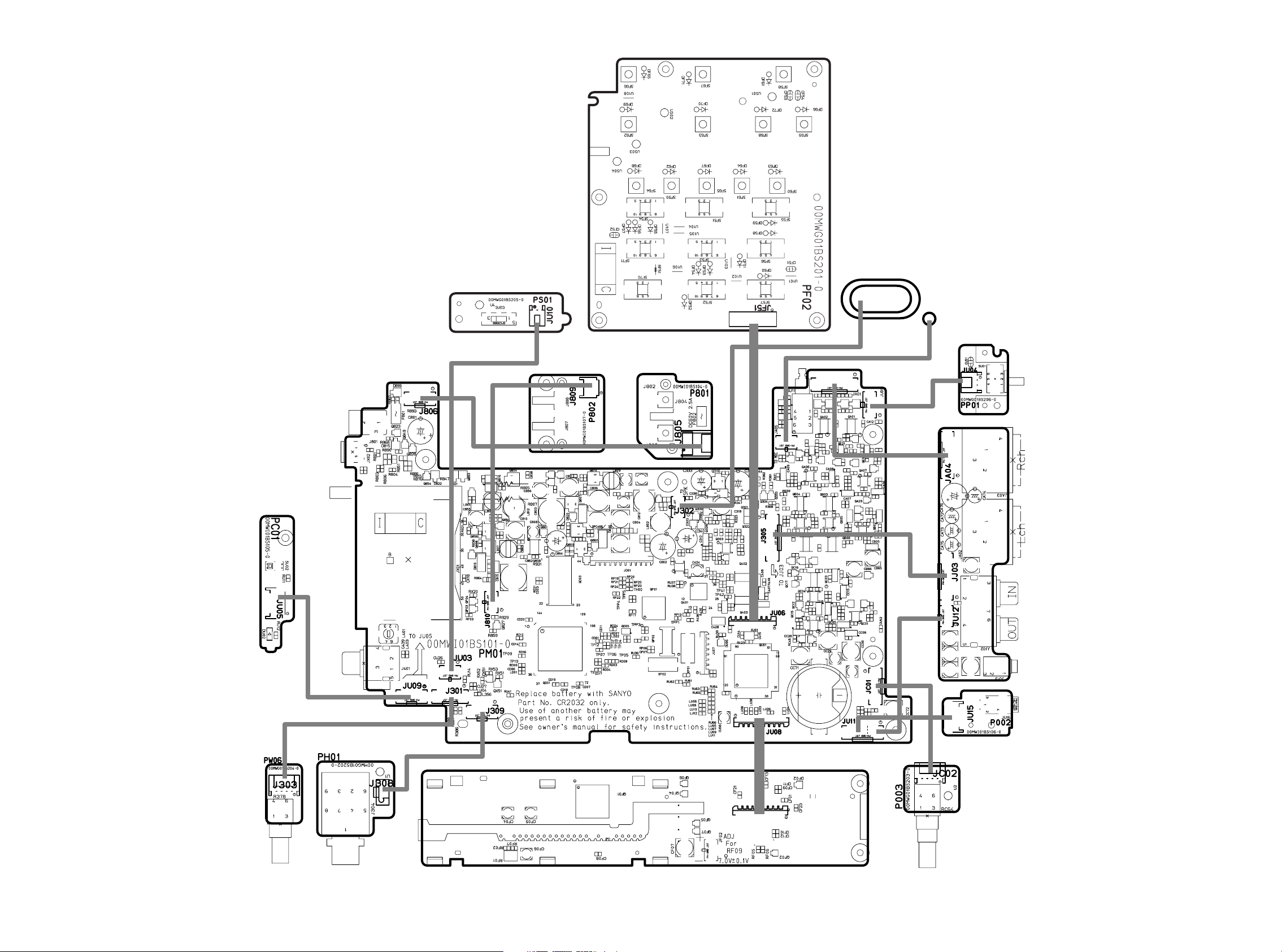
10. PARTS LOCATION...................................................................................................................... 39
11. MICROPROCESSOR AND IC DATA........................................................................................... 47
12. EXPLODED VIEW AND PARTS LIST ......................................................................................... 61
13. ELECTRICAL PARTS LIST......................................................................................................... 63
DC IN 15V
CHARGE
-
+
DIGITAL
OUT
IN
3210
HP/SPK VOLUME
PHONES
Solid State Recorder
SOLID STATE RECORDER PMD671
SOURCE
TRACK JUMP
REC
UNDO
POWER
TOTAL
A-B
TRACK
TIME
REMAIN
RE
kbps
C
TRACK
M
A
RK
L
-
dB
kHz
R
A
M
PM
40 20 12 6 2 0
INT
MIC
LINE
S.SKIP
MARGIN RESET
MENU/STORE
REC PAUSE
OVER
-
dB
STEREO
FILE
L
R
MONITOR
AUDIO OUT
SINGLE
ALL
OFF
OFF
ON
PRE REC REPEAT ANC
OFF
ON
OFF
ON
INPUT LOCK EDL PLAY
A-B REPEATINPUT
-/F.REV F.FWD/+
PLAY/PAUSE STOP
/
ENTER
REC
KEY LOCKLIGHTDISPLAY
EDIT
MARK
TABLE OF CONTENTS
-20dB
0dB
MIC ATT
FLAT
LIMITER
ALC MANUAL
REC LEVEL
CANCEL
645
MIC
L
R
REC
LEVEL
PHANTOM
R
PUSH
MIC
PUSH
L
LINE
LINE OUT
+48V
ON
OFF
12
3
3 COLD2 HOT
IN
12
3
1 GND
L
IN
R
REMOTE 1
REMOTE 2
PMD671
Please use this service manual with referring to the user guide ( D.F.U. ) without fail.
PMD671
Part no. 90M01BS855010
First Issue 2005.02
MJI
Page 2

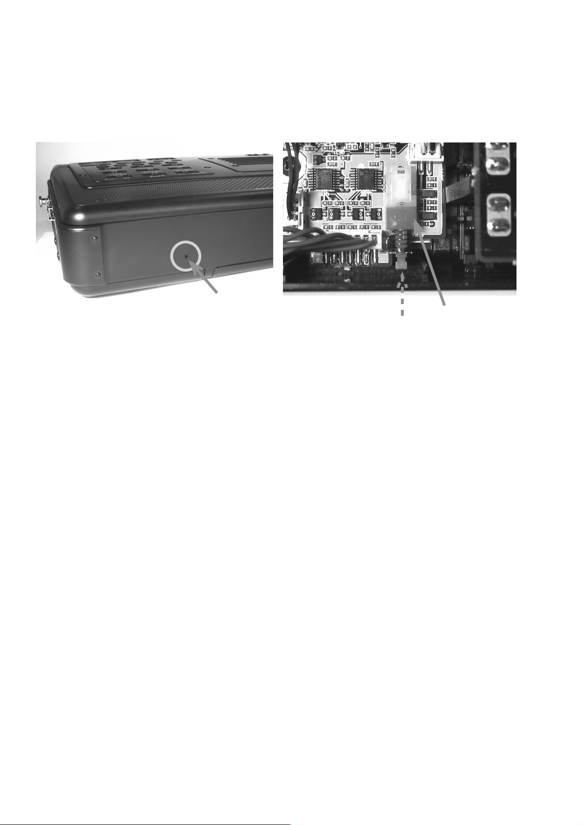
The exchange of the lithium battery(ZU01 : CR2023).
ද
CAUTION
Danger of explosion if battery is incorrectly replaced.
Replace only with the same or equivalent type.
ȪȁǦȠᩓ൷
ᩓ൷ǛᛚƬƯʩƢǔƱ༪ႆƢǔүᨖƕƋǓLJƢŵ
ӷɟӍƸӷሁƷƷNjƷƴƷLjʩƠƯƘƩƞƍŵ
(ZU01 : CR2032)
ද
ƷʩƴƭƍƯ
SHOCK, FIRE HAZARD SERVICE TEST :
CAUTION : After servicing this appliance and prior to returning to customer, measure the resistance between either primary AC
cord connector pins ( with unit NOT connected to AC mains and its Power switch ON ), and the face or Front Panel of product
and controls and chassis bottom.
Any resistance measurement less than 1 Megohms should cause unit to be repaired or corrected before AC power is applied,
and verifi ed before it is return to the user/customer.
Ref. UL Standard No. 1492.
In case of diffi culties, do not hesitate to contact the Technical
Department at above mentioned address.
030307MIT
Page 3

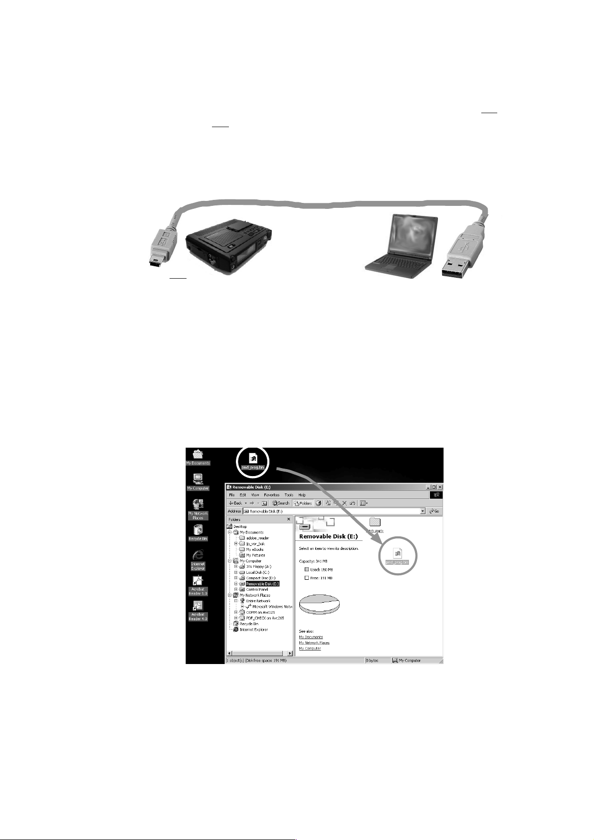
1. TECHNICAL SPECIFICATIONS
Digital audio system
System..................................................Solid State Recorder
Usable Media............................................ CF memory cards
(Microdrive) cards
Recording and media methods
.mp2.................................... MPEG1 Layer II compression
.mp3................................... MPEG1 Layer III compression
.mp3..................................MPEG2 Layer III compression*
........................................... *for all half sample rates.
PCM.................................................. 16/24 bit linear PCM
Recording bit rate (selectable)
MP2 mono .......................... 192, 128, 96, 64, 48, 32 kbps
MP2 stereo ....................... 384, 256,192,128, 96, 64 kbps
MP3 mono .............. 160, 128, 80, 64, 40, 32, 24, 16 kbps
MP3 stereo ......... 320, 256, 160, 128, 80, 64, 40, 32 kbps
Sampling frequency
Analog .........................96, 88.2, 48, 44.1 kHz(24bit PCM)
48, 44.1, 32, 24, 22.05, 16, 12, 11.025, 8 kHz(16bit PCM
............................................... 48, 44.1, 32 kHz(MP2)
........................ 48, 44.1, 32, 24, 22.05, 16 kHz(MP3)
Digital..............................................96, 88.2, 48, 44.1 kHz
Number of channels .............................. 2 (stereo), 1 (mono)
Frequency response..................................... 44 kHz (-0.5dB)
Signal-to-Noise Ratio
IEC-A weighted................................................LINE 92 dB
.................................................................. MIC 65 dB
Total Harmonic Distortion
at 0 VU(PCM) ................................................. LINE 0.01%
................................................................. MIC 0.03%
Dynamic Range............................................................94 dB
Inputs
MIC IN L/R
Type.................................. XLR (1:GND, 2:HOT, 3:COLD)
Input Sensitivity(MIC) .......................1.2 mVrms/ 3 kohms
LINE IN L/R
Type.................................................................... RCA jack
Input Sensitivity(LINE)................... 300 mVrms/ 22 kohms
DIGITAL IN
Type.................................................................... RCA jack
Input impedance.................................................. 75 ohms
Standard input level............................................. 0.5 Vp-p
Sampling frequency........................ 96, 88.2, 48, 44.1 kHz
Format ......................................... SPDIF (IEC 958 TypeII)
Standard output level........................................... 0.5 Vp-p
Sampling frequency........................ 96, 88.2, 48, 44.1 kHz
Format ........................................ SPDIF (IEC-958 Type II)
General
Headphone Output power ........................20 mW/ 32 ohms
Speaker Output power................................70 mW/ 4 ohms
Phantom power ................................................+48V/ 7 mA
Power consumption
Recording/Playback.....................................................6 W
Charging............................................................12 W max
Standby (battery driven) ........................................2.9 mW
Battery life (Alkaline).................................. 6 hours (typical)
Dimensions
Width ........................................................ 264 mm (10.4”)
Height ........................................................... 55 mm (2.0”)
Depth.......................................................... 185 mm (7.3”)
Weight ................................................ 1.3 kg (2 lbs. 14 oz.)
Included accessories
AC adapter ......................................................................1
Battery carrier.................................................................. 1
Carry strap....................................................................... 1
Carry strap retainers........................................................ 2
Screws (ISO 3x10 mm) ...................................................3
Plastic pin and retainer.................................................... 1
USB cable........................................................................ 1
User Guide ......................................................................1
Optional accessories**
Ni-Cd battery pack................................................ RB1100
Ni-MH battery pack............................................... RB1651
Battery charger....................................................... BC600
Carrying cover (vinyl)............................................CLC670
Carrying bag........................................................ PRC300
Professional reporter’s bag.................................. PRC600
Attache carrying case.............................................. CA200
**See www.d-mpro.com for details.
*Specifi cations subject to change without notice.
Outputs
LINE OUT L/R
Type.................................................................... RCA jack
Standard level................................. 2 Vrms max./2 kohms
DIGITAL OUT
Type.................................................................... RCA jack
Output impedance ............................................... 75 ohms
1
Page 4
2. FACTORY/SERVICE MODE
Ȣȸȉ
Ȣȸȉ
Ȣȸȉ
ᄩᛐ
ƖƑᡮࡇᄩᛐ
A. FACTORY MODE
To reset all settings to default status ,follow the procedure
below.
1) When Power Standby mode, While pressing MARK
or MARK and INPUT buttons, Slide POWER switch
to turn on the unit. ( /N uses MARK button. /F/U uses
MARK button.)
2) FACTORY name is displayed on LCD. The unit becomes
the setup of default automatically.
B. SERVICE MODE
1. Micro-Processor Version check
1) Insert the CompactFlash, When Power Standby mode,
While pressing A-B REPEAT and
POWER switch to turn on the unit.
2) VIRSION name is displayed on LCD with blink, then press
PLAY/PAUSE button, VIRSION is displayed on LCD.
Example : DSP 02.06
MPU B0004
EDIT buttons, Slide
DSP XX.XX
2. FACTORY/SERVICE
A. FACTORY
ǹǿȳȐǤཞƔǒŴ
1
LJƨƸ
ǛǹȩǤȉƠLJƢŵද =N? ӼƚƸ
ȁ
=
? ӼƚƸ
F/U
2FACTORY
Ȣȸȉ
MARK
Ȝǿȳ
MARK
ƱᘙᅆƕưLJƢŵᐯѣႎƴЈᒵƷᚨܭƴƳǓLJ
Ȣȸȉ
INPUT
ǛƠƳƕǒ
Ȝǿȳ
Ȝǿȳ
ǛƠLJƢŵ
Ƣŵ
Ʊ
Ȣȸȉ
ᄩᛐ
ƕλƞǕƯƍǔཞưŴ
Ȝǿȳ
ǛƠƳƕǒ
EDIT
B. SERVICE
1. VERSION
1CompactFlash
ǿȳ
ȩǤȉƠLJƢŵ
2) DISPLAYƴVERSION
Ʊໜ๒ᘙᅆƞǕƨǒ
ȜǿȳǛƠƯȐȸǸȧȳᄩᛐǛƠLJƢŵ
ᘙᅆ
DSP 02.06
MPU B0004
Ʊ
MARK
POWER
MARK
A-B REPEAT
POWER
Ȝǿȳ
ǹǤȃ
ȜǿȳŴ
Ȝ
ǹǤȃȁ
Ǜǹ
PLAY/PAUSE
TOTAL
RE
TRACK
M
A
RK
REMAIN
C
TRACK
kbps
TIME
A-B
MPU XX.XX
3) Turn off power to quit Service mode.
2. CompactFlash read/write speed check
1) Insert the CompactFlash, While pressing A-B REPEAT
and EDIT buttons, Slide POWER switch to turn on the
unit.
2) VIRSION name is displayed on LCD with blink, then press
-/F.REV or F.FWD/+ button.
3) CARD CHECK name is displayed on LCD with blink, then
press PLAY/PAUSE button.
The check of Read/write speed is started. After the
check fi nishes, the number of data transfer rate (kbps) is
displayed.
Start (progress) End
Example : XXX% Read:3606
C
RK
TRACK
REMAIN
Read:XXXX
A-B
TIME
kbps
EXECUTING Write:3606
TOTAL
RE
TRACK
M
A
L
-
40 20 12 6 2 0
dB
kHz
R
M
A
PM
INT
MIC
LINE
3SERVICE
ȢȸȉᚐᨊƸŴᩓเǛЏǓLJƢŵ
2. CompactFlash
1CompactFlash
Ʊ
ǿȳ
ƕλƞǕƯƍǔཞưŴ
EDIT
Ȝǿȳ
OVER
-
S.SKIP
ƖƑᡮࡇᄩᛐ
dB
ǛƠƳƕǒ
A-B REPEAT
POWER
ȩǤȉƠLJƢŵ
2DISPLAYƴVERSION
ȳ
Ȝǿȳ
LJƨƸ
3 DISPLAYƴCARD CHECK
PAUSE
ȜǿȳǛƠƯƖƑᡮࡇƷᄩᛐǛڼƠLJƢŵ
ܦʕƢǔƱȇȸǿȸ᠃ᡛᡮࡇᲢ
Ʊໜ๒ᘙᅆƞǕƨǒ
F.FWD/+
ȜǿȳǛƠLJƢŵ
Ʊໜ๒ᘙᅆƞǕƨǒ
ᲣƕᘙᅆƞǕLJƢŵ
kbps
ڼᲢᡶࡇ ܦʕ
ᘙᅆ
XXX% Read:3606
EXECUTING Write:3606
L
-
40 20 12 6 2 0
dB
kHz
R
M
A
PM
INT
MIC
LINE
S.SKIP
OVER
-
dB
ǹǤȃȁ
-/F.REV
PLAY/
Ȝ
Ǜǹ
Ȝǿ
If "about 3000 or less" number is displayed, the
CompactFlash is not correct (Because read/write speed is
slow, the unit has the possibility that sound is interrupted
and stop during recording).
Insert the correct CompactFlash.
4) Turn off power to quit Service mode.
Write:XXXX
2
ᘙᅆƞǕƨȇȸǿȸ᠃ᡛᡮࡇᲢ
Უƕኖ
kbps
ƷئӳᲴƖƑᡮࡇƕƍໝŴ᪦ᡦɶưഥLJǔŴLJƨ
Ƹ᪦ЏǕƕႆဃƢǔӧᏡࣱƕƋǓLJƢŵ
CompactFlash
КƷNjƷƴʩƠƯƘƩƞƍŵ
4SERVICE
ȢȸȉᚐᨊƸŴᩓเǛЏǓLJƢŵ
kbps
ˌɦ
Ǜ
Page 5
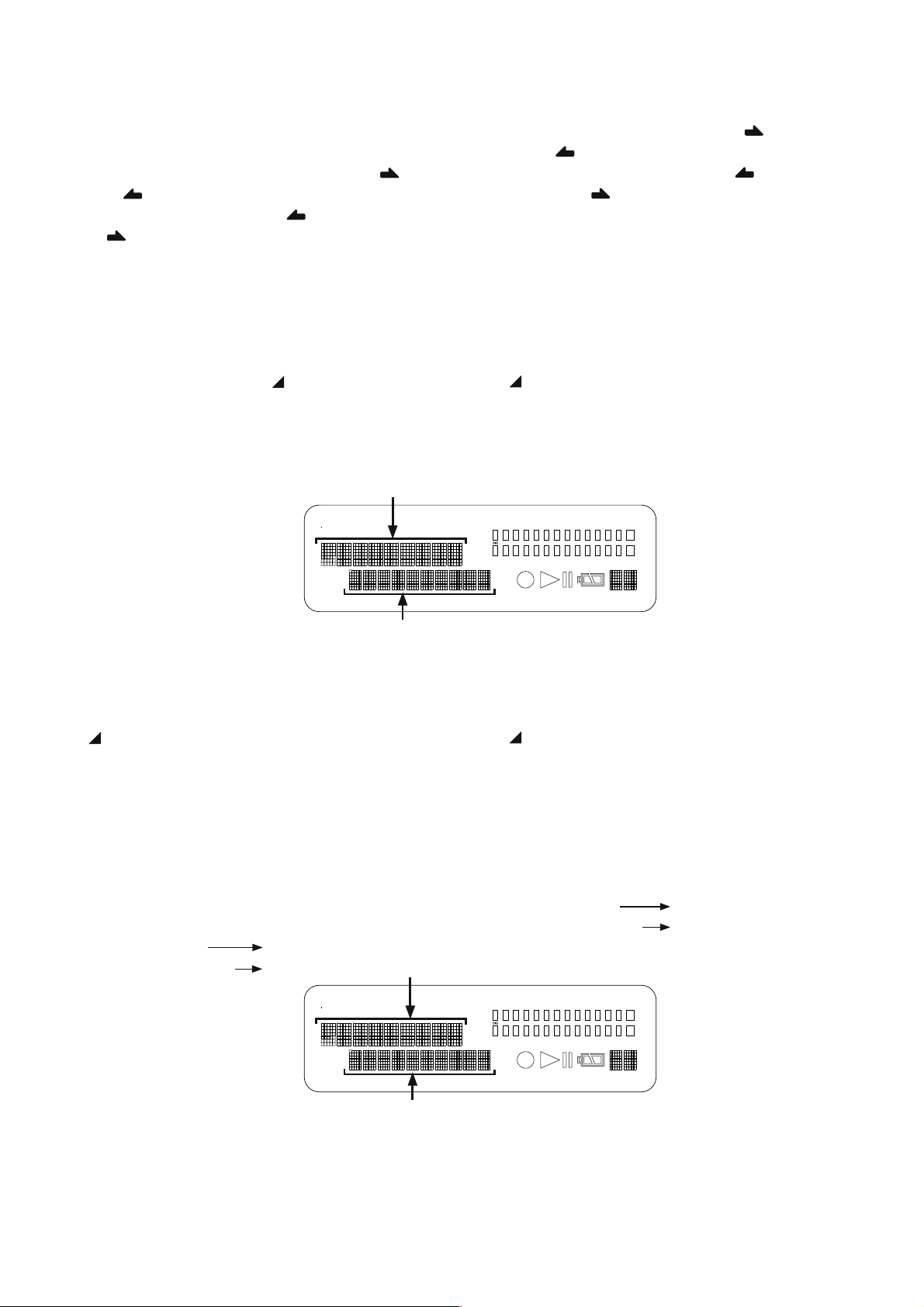
3. LCD CONTRAST ADJUSTMENT
᠗ࡇᩓןᛦૢ
Ўᚐ૾ඥ
1. Connect the TEST POINT (See below) with the tester.
2. Turn the variable resistor RF01(RF09) so that the reading
of the tester becomes 7.0 V ± 0.1 V and confi rm the
contrast of the LCD becames maximum.
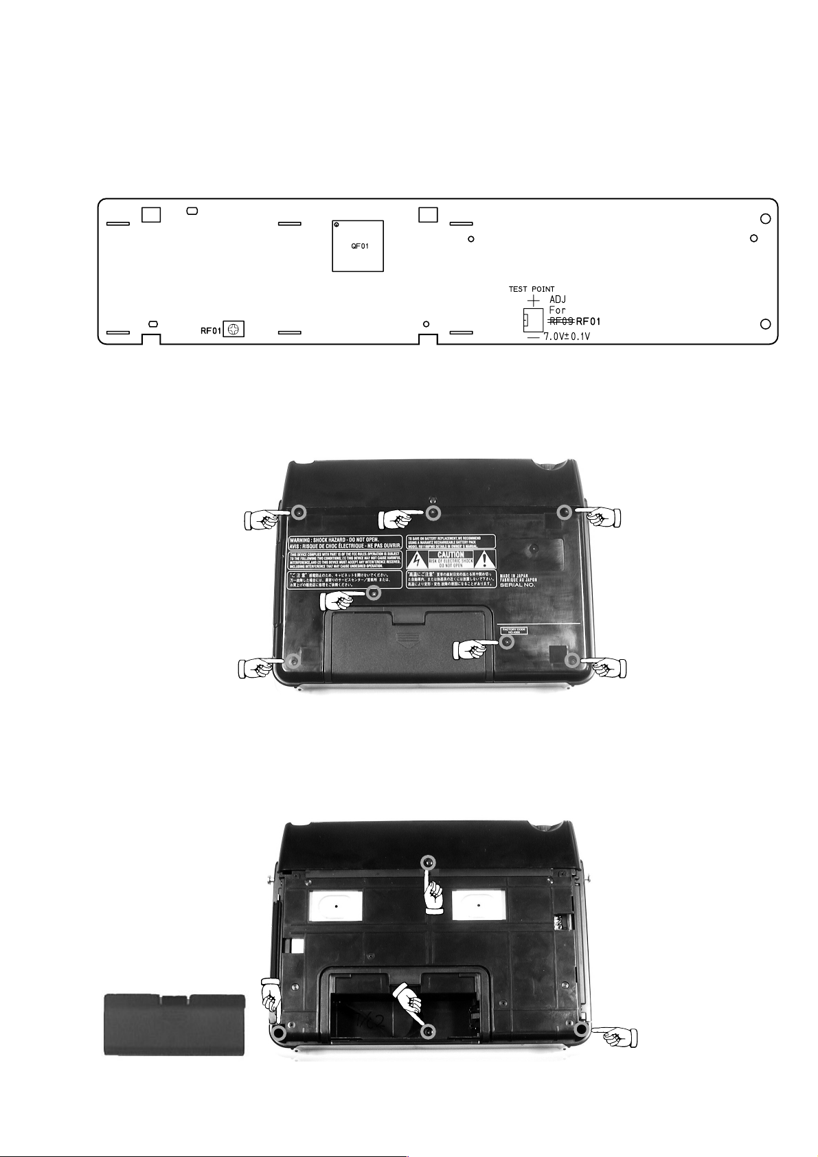
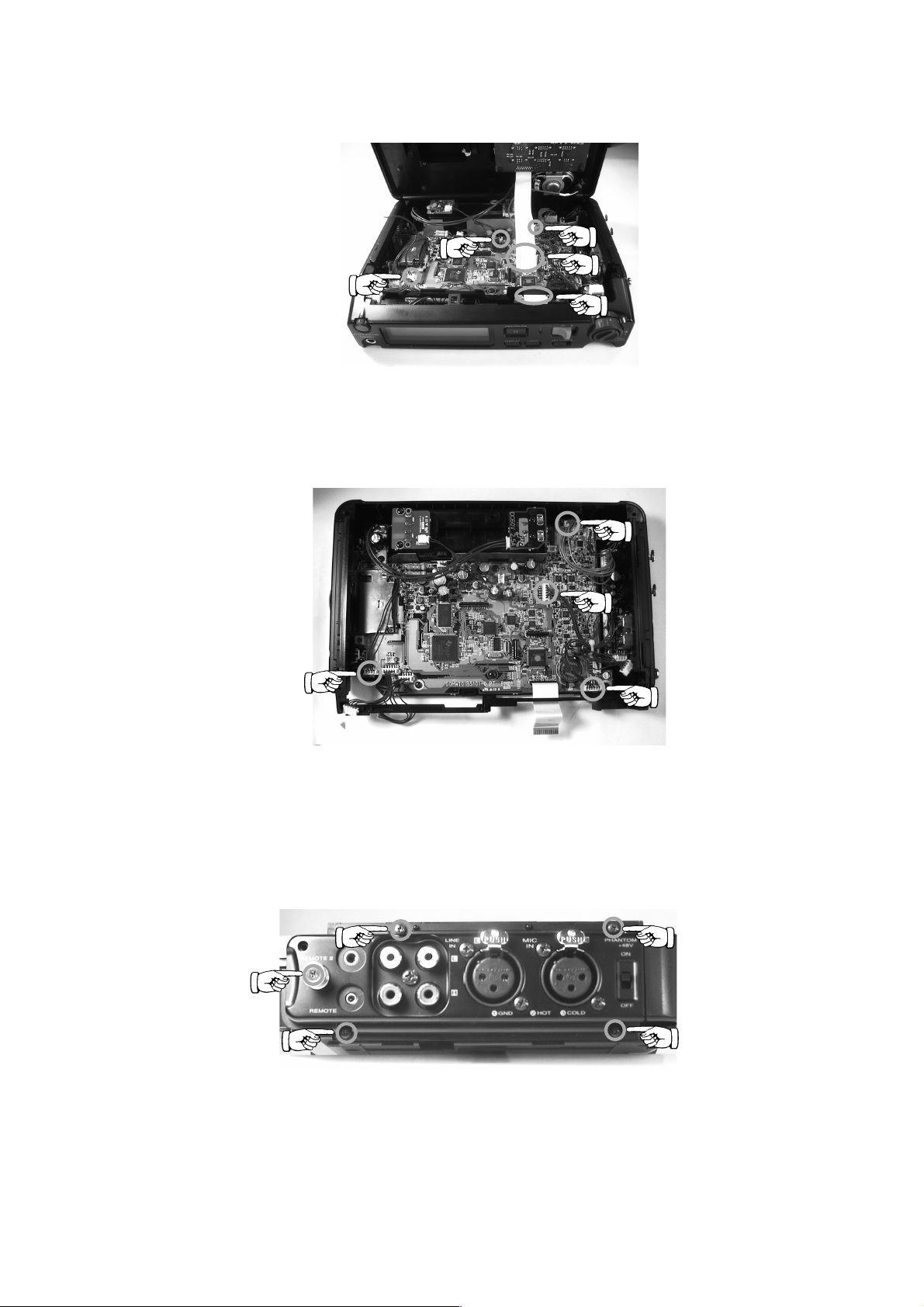
4. HOW TO DISASSEMBLE
1) Remove 7 screws as shown in Fig.1.
3. LCD
1TESTPOINT
2LCD
4.
1
ɦ1ƴᅆƢǻȃȈࡁ᩿ƷȍǸ7ஜǛٳƠLJƢŵ
ࡁᔟǛٳƠLJƢŵ
᠗ࡇᩓןᛦૢ
ƴȆǹǿȸǛዓƠŴ᠗ࡇᩓןǛยǓƳƕǒȜ
ȪȥȸȠ
ƠƳƕǒ᠗ࡇᩓןǛ7
Ўᚐ૾ඥ
RF01(RF09)
Ǜദ᩿ƔǒᙸƯŴdzȳȈȩǹȈƕஇٻƴƳǔƜƱǛᄩᛐ
Ʒ৽৴ǛᛦૢƠLJƢ ᳹
0V
01V
ƴᛦૢƠLJƢ ᳹
±
2) Remove the battery cover.
3) Remove 4 screws as shown in Fig.2.
<Fig.1 Position of 7 screws>
2
ȐȃȆȪȸǫȐȸǛٳƠLJƢŵ
3
ɦ2ƴᅆƢȍǸ4ஜǛٳƠLJƢŵ
<Fig.2 Position of 4 screws>
3
Page 6
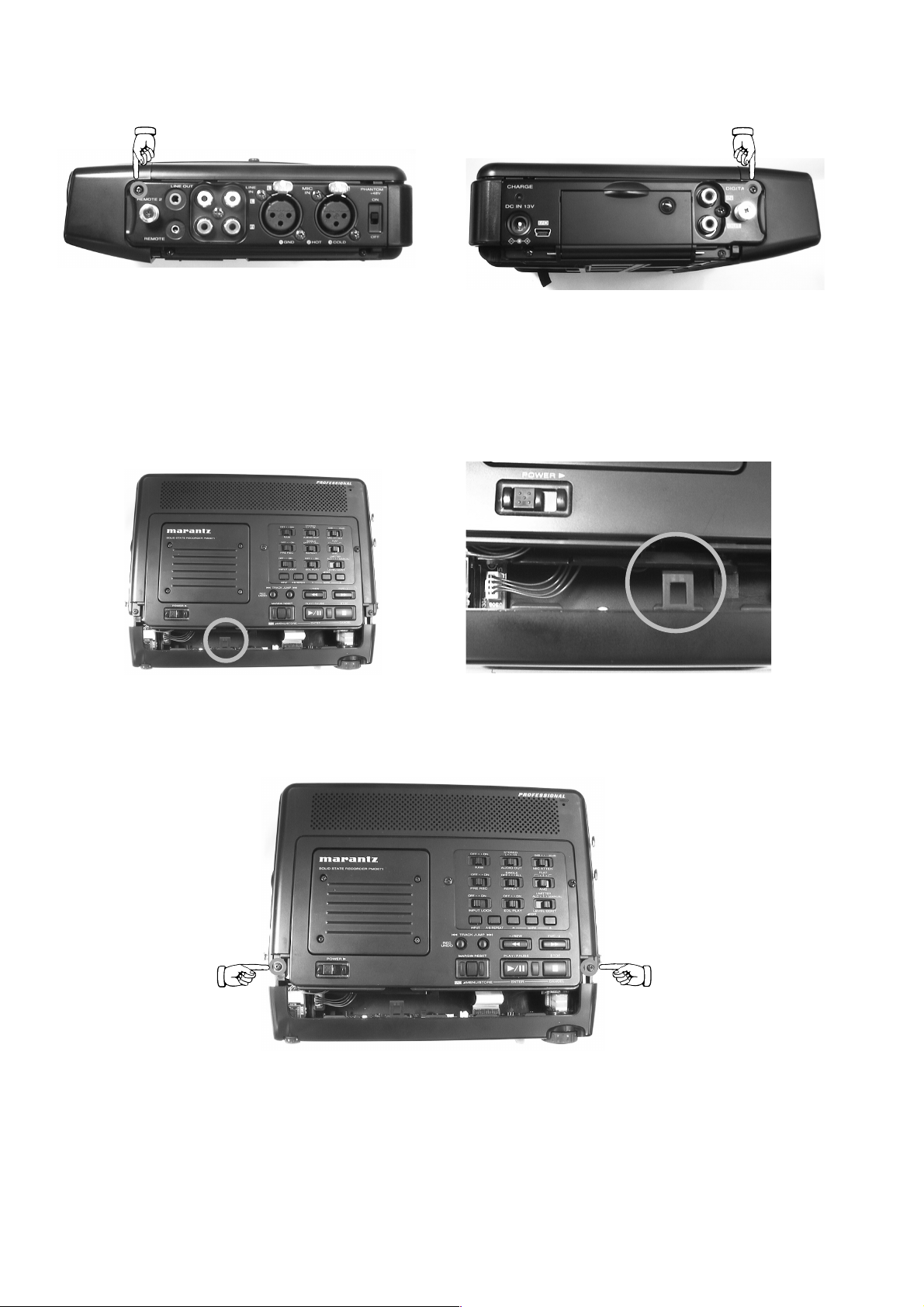
4) Remove 2 screws from both sides as shown in Fig.3 and
Fig.4.
<Fig.3 Po si tion of screw> <Fig.4 Position of screw>
5) Remove the front panel, holding it and pushing down with
thumb as shown in Fig.5 and Fig.6.
Cautions :
When removing the front panel, take care not to damage
the cable and connectors.
4
ɦ3᳸4ƴᅆƢɲǵǤȉƷȍǸᚘ2ஜǛٳƠLJƢŵ
5
ȕȭȳȈȑȍȫǛɦ5᳸6ƷˮፗǛưƞƑƳƕǒٳ
ƠLJƢŵ༯ǛٳƢǑƏƴƞƑƳƕǒЭ૾ӼƴࡽƖȕȭȳ
ȈȑȍȫǛٳƠLJƢŵ
දᲴѬƍǑƘࡽƘƱȕȭȳȈȑȍȫƴጟƕǔ
ࢌǒǕƯdzȍǯǿƕᄊƢǔǕƕƋǓLJƢŵ
FPC
ƕࡽƬ
<Fig.5 Holding position> <Fig.6 Removing the front panel>
6) Remove 2 screws as shown in Fig.7.
6
ɦ7ƴᅆƢȍǸ2ஜǛٳƠLJƢŵ
<Fig.7 Position of 2 screws>
4
Page 7
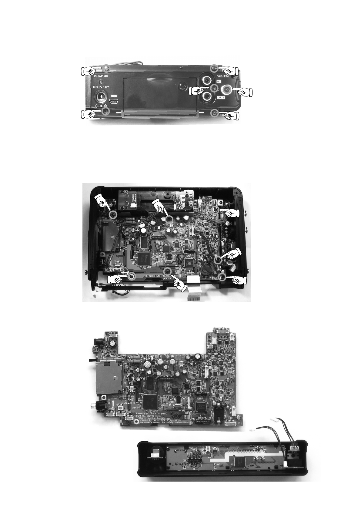
7) Remove 5 connectors as shown in Fig.8. And remove the
top case.
<Fig.8 Position of connectors>
7
ȈȃȗDZȸǹǛƪɥƛLJƢŵɦ8ƴᅆƢ5ȶƷdzȍǯ
ǿǛٳƠŴȈȃȗDZȸǹǛٳƠLJƢŵ
8) Remove 4 connectors as shown in Fig.9.
9) Remove 5 screws.
Then remove side panel of Audio I/O side.
ɦ9ƴᅆƢdzȍǯǿ4ȶǛٳƠLJƢŵ
8
<Fig.9 Position of 4 connectors>
9
ȍǸ5ஜǛٳƠŴ#WFKQ λЈщƷǵǤȉȑȍȫǛٳƠLJƢŵ
<Fig.10 Position of 5 screws>
5
Page 8
10) Remove 6 screws.
Then remove side panel of CompactFlash side.
<Fig.11 Position of 6 screws>
10
ȍǸ6ஜǛٳƠŴdzȳȑǯȈȕȩȃǷȥƷǵǤȉȑȍȫ
ǛٳƠLJƢŵ
11) Remove 7 screws.
Then remove the PCB.
ȍǸ ஜǛٳƠŴؕெǛٳƠLJƢŵ
<Fig.12 Position of 7 screws>
6
Page 9
5. DSP(QD01) FIRMWARE UPDATE PROCE-
ƷǢȃȗȇȸȈ૾ඥ
࣏ᙲೞ֥
ዓ૾ඥ
ǢȃȗȇȸȈ૾ඥ
DURE
Necessary Equipment
•
Windows PC((Windows2000 or WindowsXP)
•
USB cable (USB 4Pin - mini USB 5pin)
•
CompactFlash (with format)
•
Update Disc (90M-PMD671CDR)
Connection
1. Connect Windows PC and PMD671 with USB cable
2. Insert the CompactFlash
mini USB 5pin
Writing procedure
NOTICE : Don't turn off the power during the update. When
turn off the power, you must change Flash Rom
(QD01).
1. While pressing MARGIN RESET button, Slide POWER
switch to turn on the unit.
2. "USB ONLINE" is displayed on LCD.
3. It confi rms that it was recognized as Removable Disk
(CompactFlash) by a PC.
4. "pmd_prog.bin" of the update disk is copied to the route of
Removable Disk(CompactFlash).
5. DSP (QD01) fi rmware
࣏ᙲೞ֥
• Windows PCWindows2000
• USB
•
•
ዓ૾ඥ
1WindowsPCƱPMD671
2
ǢȃȗȇȸȈ૾ඥ
ද ǢȃȗȇȸȈɶƸᩓเǛЏǒƳƍưƘƩƞƍŵᩓเǛЏǔ
1PMD671ƷMARGIN RESET
2PMD671
3WindowsPC
4
DZȸȖȫ
dzȳȑǯȈȕȩȃǷȥ
ǢȃȗȇȸȈȇǣǹǯ
dzȳȑǯȈȕȩȃǷȥǛ
Flash ROM(QD01)
Ʊ
ǹǤȃȁǛǹȩǤȉƠᩓเǛλǕLJƢŵ
ƠƯᛐᜤƞǕƨƷǛᄩᛐƠLJƢŵ
ǢȃȗȇȸȈȇǣǹǯƷ
ǹǯ
CompactFlash)
USB 4Pin USB
ƷȇǣǹȗȬǤƴ
ƴȪȠȸȐȖȫȇǣǹǯ
ƷǢȃȗȇȸȈ૾ඥ
WindowsXP
LJƨƸ
5pin
ȟȋ
CompactFlash
ᲢȕǩȸȞȃȈฎLjᲣ
90M-PMD671CDR
USB
ƱǛ
PMD671
ǛʩƢǔ࣏ᙲƕƋǓLJƢŵ
DZȸȖȫưዓƠLJƢŵ
ƴࠀƠᡂLjLJƢŵ
ȜǿȳǛƠƳƕǒ
USBONLINE
ƱᘙᅆƞǕLJƢŵ
CompactFlash)
pmdAprogbin
ƷȫȸȈƴdzȔȸƠLJƢŵ
ǛȪȠȸȐȖȫȇǣ
POWER
Ʊ
5. Disconnect USB cable from the unit, then turn off POWER
switch.
6. Keep inserting the CompactFlash, turn on POWER switch.
7. DSP Firmware updating will be done automatically.
8. Light up all the LCD dot.
9. Uploading takes about one minute.
5USB
6
7
8
9
DZȸȖȫǛ
dzȳȑǯȈȕȩȃǷȥǛࠀƠᡂǜƩLJLJ
λǕLJƢŵ
ᐯѣႎƴ
ƜƷƱƖȇǣǹȗȬǤƸμໜ໊ƠLJƢŵ
᧓Ƹኖ1ЎDŽƲưƢŵ
PMD671
DSPƷfi rmware
ƔǒٳƠƯᩓเǛЏǓLJƢŵ
ǛƖƑLJƢŵ
7
PMD671
ƷᩓเǛ
Page 10

10. When the updatiing is fi nished, information of Compact-
Ȣȸȉ
ᄩᛐ
Flash is displayed on LCD.
11. Turn off POWER switch.
The fi rmware has been updated. Do the next procedure.
12. Connect Windows PC and PMD671 with USB cable
13. Repeat the same procedure No1., No2. and No3.
14. "pmd_prog.bin" which wrote it in the Removable
Disk(CompactFlash) is delete.
NOTICE :
When "pmd_prog.bin" isn't delete from the compacFlash,
The set becomes the mode of update of fi rmware every
time to turn on the unit.
15. Disconnect USB cable from the PMD671, then turn off
POWER switch.
16. Check the version number of the fi rmware
Refer to 2-page "SERVICE MODE" for "Micro-Proces-
sor Version check" confi rmation.
10
ƖƑƕኳǘǔƱȇǣǹȗȬǤƴǫȸȉإƕᘙᅆƞǕ
LJƢŵ
11PMD671
ˌɥưƖƑ˺ಅƸኳʕưƢŵ
ƷЪᨊ˺ಅƠLJƢŵ
12USB
13
ϐࡇŴɥᚡ1Ŵ2Ŵ3Ʒદ˺ǛƠLJƢŵ
14
ȪȠȸȐȖȫȇǣǹǯ
pmd_prog.bin
දƜƷદ˺ǛƠƳƍƱ
15PMD671
16.VERSION
2ȚȸǸ
ᄩᛐǛƠLJƢŵ
17
ƖᡂǜƩ
ʕưƢŵ
ƷᩓเǛЏǓLJƢŵ
DZȸȖȫǛዓƠLJƢŵ
ǛЪᨊƠLJƢŵ
PMD671
fi rmware
ƷƖƑѣ˺ƴλƬƯƠLJƍLJƢŵ
ƷᩓเǛЏǓ
ƷᄩᛐǛƠLJƢŵ
USB
"B. SERVICE
fi rmware
ƷȐȸǸȧȳƕദƠƚǕƹƖƑܦ
ƭƮƚƯŴ
CompactFlash)
ƷᩓเλǕƨŴׅ
DZȸȖȫǛٳƠLJƢŵ
Ȣȸȉ"Ʒ
"
1. VERSION
pmd_prog.bin
ϋƴƖᡂǜƩ
ᄩᛐ"ư
8
Page 11
6. MAIN MICROPROCESSOR (QU01) UPDATE
ƷǢȃȗ
ȇȸȈ૾ඥ
࣏ᙲೞ֥
ዓ૾ඥ
ǢȃȗȇȸȈ૾ඥ
PROCEDURE
Necessary Equipment
•
Windows PC (Windows20 or WindowsXP)
•
USB cable (USB 4Pin - mini USB 5pin)
•
CompactFlash (with format)
•
Update Disc (90M-PMD671CDR)
Connection
1. Connect Windows PC and PMD671 with USB cable.
2. Insert the CompactFlash.
mini USB 5pin
Writing procedure
When you have already written the update fi le in CompactFlash, please go to No8.
1. While pressing MARGIN RESET button, Slide POWER
switch to turn on the unit.
2. "USB ONLINE" is displayed on LCD.
3. It confi rms that it was recognized as Removable Disk
(CompactFlash) by a PC.
4. "PMD671.mot" of the update disk is copied to the route of
Removable Disk (CompactFlash).
6.
MAIN MICROPROCESSOR (QU01)
ȇȸȈ૾ඥ
࣏ᙲೞ֥
• Windows PCWindows2000
• USB
•
•
ዓ૾ඥ
1WindowsPCƱPMD671
2
ǢȃȗȇȸȈ૾ඥ
ଏƴ
ئӳƸ
1PMD671ƷMARGIN RESET
2PMD671
3WindowsPC
4
DZȸȖȫ
dzȳȑǯȈȕȩȃǷȥ
ǢȃȗȇȸȈȇǣǹǯ
dzȳȑǯȈȕȩȃǷȥǛ
CompactFlash
ǹǤȃȁǛǹȩǤȉƠᩓเǛλǕLJƢŵ
ƠƯᛐᜤƞǕƨƷǛᄩᛐƠLJƢŵ
ǢȃȗȇȸȈȇǣǹǯƷ
ǹǯ
CompactFlash)
USB 4Pin USB
CompactFlash
90M-PMD671CDR
ƱǛ
PMD671
ƴǢȃȗȇȸȈȕǡǤȫǛƖᡂǜưƋǔ
ƴᡶǜưƘƩƞƍŵ
8
ƷȇǣǹȗȬǤƴ
ƴȪȠȸȐȖȫȇǣǹǯ
PMD671.mot
ƷȫȸȈƴdzȔȸƠLJƢŵ
USBONLINE
WindowsXP
LJƨƸ
5pin
ȟȋ
USB
DZȸȖȫưዓƠLJƢŵ
ƴࠀƠᡂLjLJƢŵ
ȜǿȳǛƠƳƕǒ
ƷǢȃȗ
ᲢȕǩȸȞȃȈฎLjᲣ
POWER
ƱᘙᅆƞǕLJƢŵ
CompactFlash)
ǛȪȠȸȐȖȫȇǣ
Ʊ
5. Click the "Unplug or Eject Hardware" on the task bar at
Windows PC, and Click the "Stop USB Mass Storage Device".
5. Windows PC
Unplug or Eject Hardware)
ٳƠ
(
ᚡচᘺፗȇȐǤǹ
ȪȃǯƠLJƢŵ
ƷǿǹǯȐȸƔǒ
Stop USB Mass Storage Device)
(
ȏȸȉǦǧǢƷܤμƳӕǓ
"
ǛǯȪȃǯƠ
"
"USB
ٻܾ
Ǜǯ
"
9
Page 12
6. Slide POWER switch to turn off the unit.
Ȣȸȉ
ᄩᛐ
7. Disconnect USB cable from the unit.
8. Disconnect AC adapter cable from the unit. Remove a
battery, if unit is equipped with it.
9. Insert a thin rod to the hole at rear panel and push the
switch (SU11) inside to turn on the update mode.
Hole of rear panel
ȪǢȑȍȫƴƋǔᆭ
6.PMD671
7.PMD671
8.PMD671
ƞǕƯƍǔئӳƸȐȃȆȪȸNjٳƠLJƢŵ
9.
ኬƍొǛƍ
ǛƠƖᡂLjȢȸȉƴƠLJƢŵ
ƷᩓเǛЏǓLJƢŵ
USB
Ɣǒ
ƔǒACǢȀȗǿǛٳƠLJƢŵȐȃȆȪȸƕᘺბ
DZȸȖȫǛٳƠLJƢŵ
PMD671
ƷᏑ᩿ƴƋǔᆭƔǒǹǤȃȁ
(SU11)
SU11
10. Keep inserting (or insert) the CompactFlash, connect AC
adapter cable to unit.
11. MPU Firmware updating will be done automatically.
12. LED of REC blinks.
13. Uploading takes about one minute.
14. When the updating was fi nished, LED of REC lights.
Update is failure when Light Emitting Diode puts out the
light. Retry update procedure.
15. Disconnect the AC adapter cable from unit. And insert
a thin rod to the hole at rear panel and push the switch
(SU11) inside to turn off the update mode.
The fi rmware has been updated. Do the next procedure.
16. Connect Windows PC and PMD671 with USB cable.
17. Repeat the same procedure No1, No2, and No3.
18. "PMD671.mot" which wrote it in the Removable Disk
(CompactFlash) is deleting.
19. Eject the Removable Disk (CompactFlash) from Windows PC (Refer to No5.).
20. Turn off POWER switch and then disconnect USB cable
from the PMD671.
21. Check the version number of the fi rmware.
Refer to 2-page "B. SERVICE MODE" for "1. Micro-
Processor Version check" confi rmation.
10.
dzȳȑǯȈȕȩȃǷȥǛࠀƠᡂǜƩLJLJ(LJƨƸࠀƠᡂǜư
PMD671ƴAC
11.
ᐯѣႎƴȡǤȳȞǤdzȳƷ
12.
ƜƷƱƖ
13.
ƖƑ᧓Ƹኖ1ЎưƢŵ
14.
ƖƑƕኳǘǔƱ
LED
15.PMD671
16.USB
17.
18.
19.Windows PC
20.PMD671
21.VERSION
2
22.
ƕෞ໊ƠƨئӳƸǢȃȗȇȸȈǛڂƠƯƍLJƢƷư
NjƏɟࡇǢȃȗȇȸȈǛᘍƬƯƘƩƞƍŵ
ᆭƔǒǹǤȃȁǛƠƯƖᡂLjȢȸȉǛᚐᨊƠLJƢŵ
ˌɥưƖƑ˺ಅƸኳʕưƢŵዓƚƯ
ᨊ˺ಅǛƠLJƢŵ
DZȸȖȫǛዓƠLJƢŵ
ϐࡇŴɥᚡ1
ȪȠȸȐȖȫȇǣǹǯ
PMD671.mot
ȚȸǸ
ᄩᛐǛƠLJƢŵ
ƖᡂǜƩ
ʕưƢŵ
ǢȀȗǿǛዓƠLJƢŵ
fi rmware
RECƷLED
ƔǒACǢȀȗǿǛٳƠŴ
2, 3
ǛЪᨊƠLJƢŵ
Ɣǒ
ƷᩓเǛЏǓ
ƷᄩᛐǛƠLJƢŵ
"B. SERVICE
fi rmware
ƕໜ๒ƠLJƢŵ
RECƷLED
Ʒદ˺ǛƠLJƢŵ
(CompactFlash)
USB Device
ƷȐȸǸȧȳƕദƠƚǕƹƖƑܦ
ǛٳƠLJƢ ɥᚡ5Ʒદ˺ ŵ
USB
DZȸȖȫǛٳƠLJƢŵ
Ȣȸȉ"Ʒ
ǛƖƑLJƢŵ
ƕໜ໊ƴ٭ǘǓLJƢŵ
PMD671
"
1. VERSION
ƷᏑ᩿ƴƋǔ
PMD671.mot
ϋƴƖᡂǜƩ
ƷЪ
ᄩᛐ"ư
)
10
Page 13
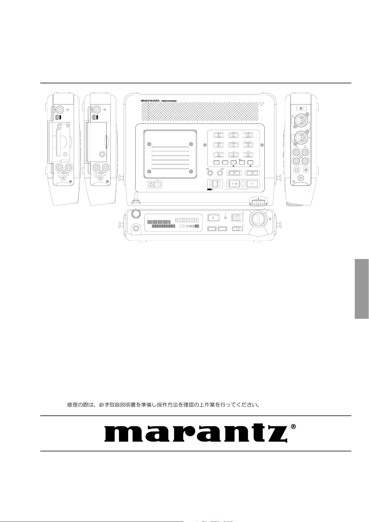
7. WIRING DIAGRAM
SPEAKER
MIC
JF01
P001
PF01
11 12
Page 14
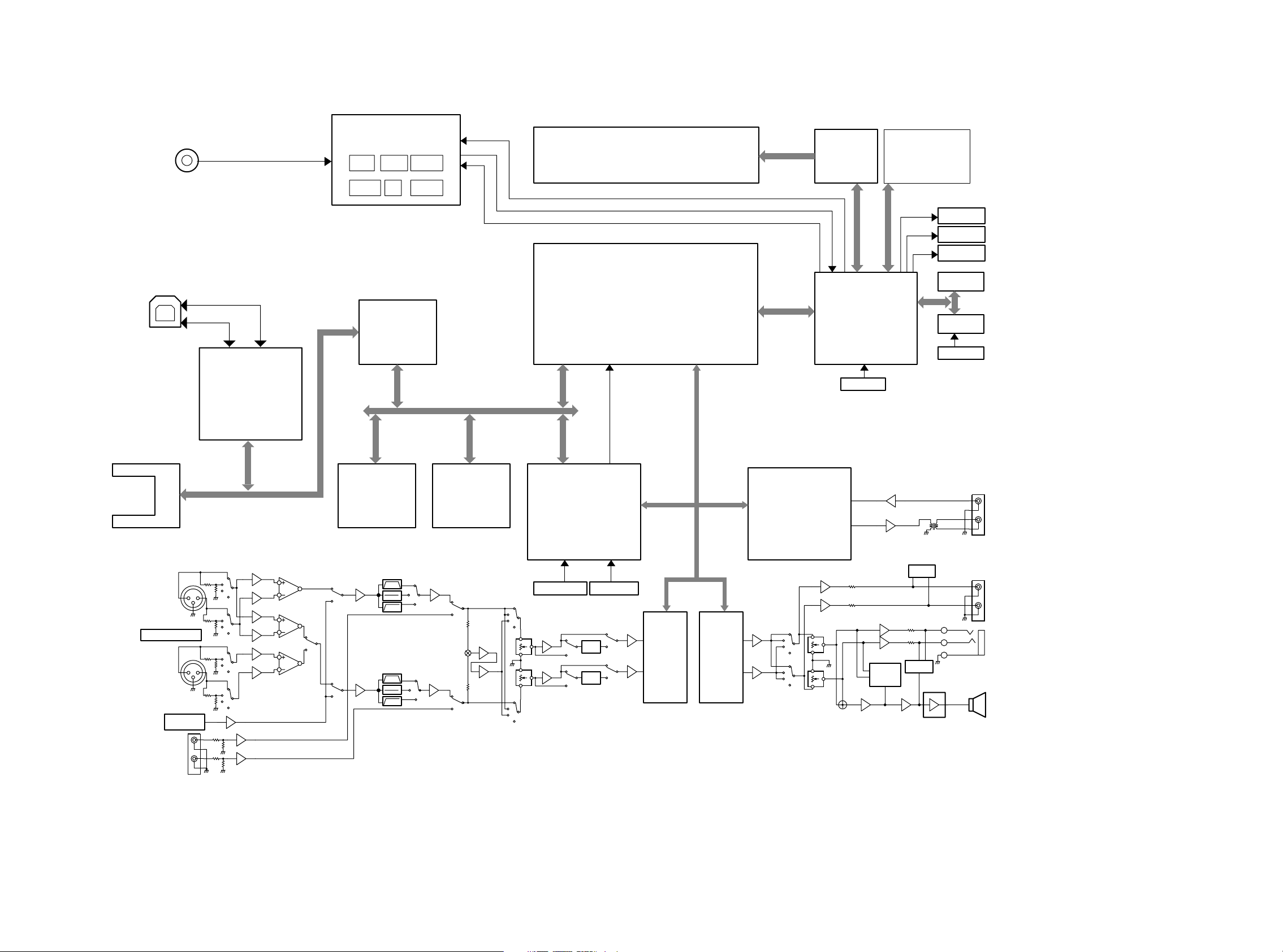
8. BLOCK DIAGRAM
DCIN
DC15V or BATT.
DC-DC POWER SUPPLY
and BATTERY CHARGER
+3.3V
+48V
+1.6V
for DSP
+3.3V
for uP
for DSP
+5V +-7V
POWER ON/OFF
BATTERY MONITOR
BATTERY CHARGE
LCD DISPLAY
VF01
LCD DRIVER
NJU6469
QF01
KEY PANNEL
POWER LED
CHARGE LED
REC LED
USB CONNECTOR
COMPACT FLASH
MICRODRIVE
Mic in L
Mic in R
PHANTOM SW
+
-
31
2
31
2
USB DRIVER
GL813
QX01
BUS BUFFER
QX03
QX04
QX05
BUS I/F
SRAM
8Mbit x 2
Cycle Time:80ns Cycle Time:90ns
Flash ROM
8Mbit x 1
QD03,QD04 QD02
ANC
ANC
CPLD
XC9536XL-VQ64-10C
QP01
22.5792MHz 24.576MHz
REC LEVEL VOL.
RC64
ALC
ALC
DSP
TMS320VC5416-160
QD01
CLK 22.5792MHz
ADC DAC
AK5380 AK4384
Q402
CODEC_DACOUT
CODEC_MCLK
CODEC_BCLK
CODEC_WS
CODEC_ADIN
Q403
HD0:HD7
DIT/DIR
AK4114
Q401
FRONT uP
HD64F2328
QU01
24.576MHz
ALARM
MUTE
MUTE
EEPROM
AT24C01A
TIMMER
RS5C372A
32kHz
DIGITAL IN(COAX)
DIGITAL OUT(COAX)
ANALOG OUT
H/P OUT
Analog in
INTERNAL
MIC
H/P VOL.
R378
SP OUT
1413
Page 15
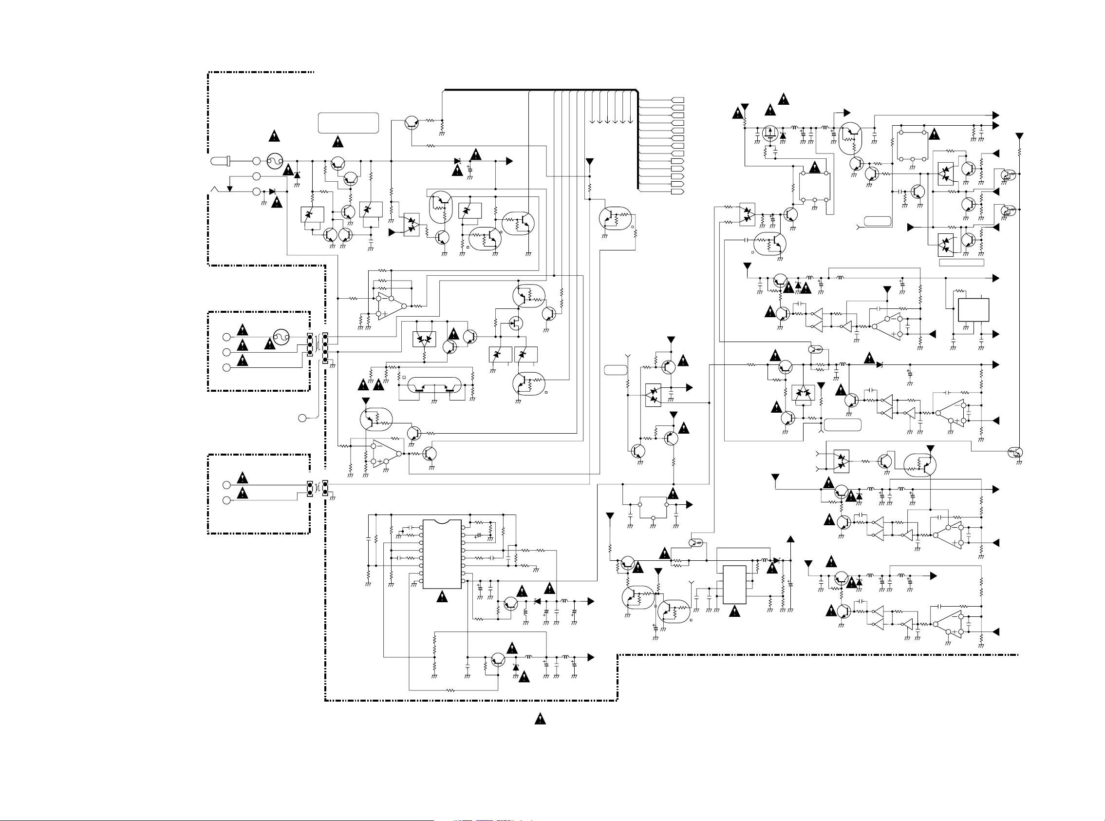
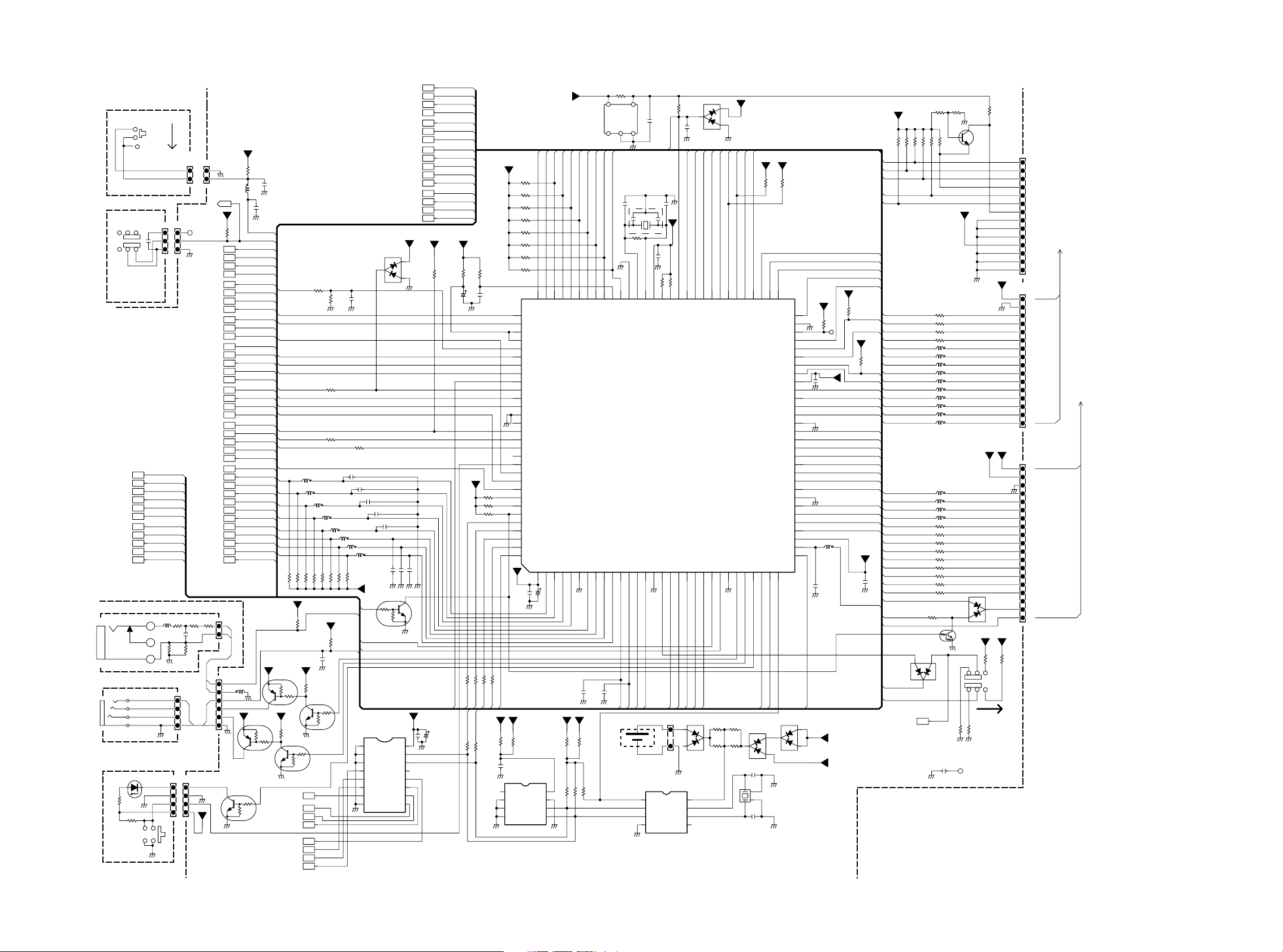
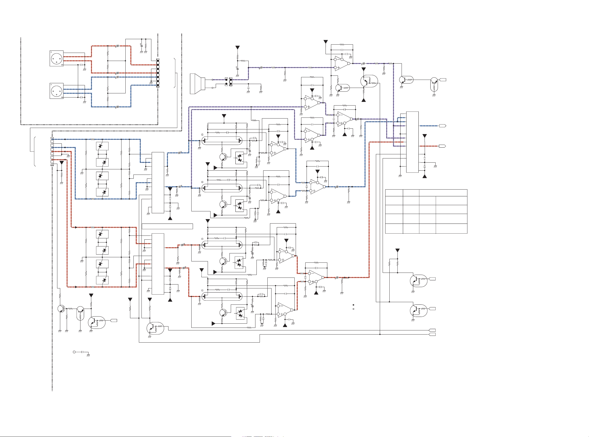
9. SCHEMATIC DIAGRAM
PM01 (A) POWER SUPPLY
WI01BS101*
OVER VOLTAGE PROTECTION
VOLTAGE REGULATOR
J801
HEC0470
DC IN
15V
TO BATTERY UNIT
J803
+
J802
-
J804
(P801)
TO BATTERY UNIT
TO NiMH Batt TEMP SENSOR UNIT
J807
J808
(P802)
F801
2.5A/60VCCF1N
1
3
D811
RB160L-40
2
GND
F802
2.5A/60VCCF1N
2.5A
WI01BS104*
To MAIN BRACKET
S2B-PH-SM3-TB
WI01BS107*
2SA1797
15.3 14.6
R831
DM
D804
RB160L-40
R893
GND
100k
R865
10k
2
D816
02CZ20Z
31
3
Q846
2SC4116
GND
J806
J805
B4B-PH-SM4
S3B-XH
3
4
2
3
1
2
1
GND
1
J810
J809
B2B-PH-SM3-TB
1
1
2
2
GND
Q801
Q845
2SC4116
3
2
2
1
1
GND
R801
R803
100k
&
231
Q862
2SA1576
1
3
R879
47k
2
1
GND
Q841
2SC4116
R891
100k
R824
15k
Q815
DTA114EU
22k
GND
3
+3VU
R804
22k
R806
4.7k
GND
C820
0.1u
2
3
R805
4.7
GND
GND
2W
GND
1
2
GND
GND
R875
4.7k
D814
02CZ15Z
2
1
+3VD
C857
0.1u
R851 100k
R815 15k
R876 DM
6
OP-AMP2/2
5
R874
DM
R807
4.7
2W
GND
2
OP-AMP1/2
34
R861
10k
R878
18k
R872
39k
R822
100k
47k
R887
GND
8
R808
100
3
R841
100k
Q802
NJM2094V
GND
GND
C839
0.01u
R836
10k
GND
Q833
2SC4116
231
31
D801
1SS301
R842
7
1k
Q802
NJM2094V
D805
1SS301
R811
100
C1
4
32 1
Q850
2SC4116
2
1
GND
1
R810
1k
C849
220p
R883
10k
R817
10k
GND
AC_IN
R897
10k
GND
R825
100k
Q823
DTA114EU
1
2
3
R901
10k
Q832
2SC4116
GND
31
2
R802
330
Q821 UMW1N
E
B1
GND
R809
3
10k
2
Q830
2SC4116
3
1
GND
12345678
1.7
1.0
1.3
1.3
Q819
BA9741FS
1.9
1.7
13.1
R924
12k
R914
33k
R826
10k
GND GND
R830
100k
RB160L-40
3
2
R890
1
2
1
2SD1802S,T
B2
R837
220
D812
2
10k
13.5
14.2
Q825
2.5
0.1
1.3
1.3
2.0
1.7
C816
0.1u
3
C801
470u/25V
GND
D815
02CZ5.6Z
2
R868
22k
31
3
GND
R888
4.7k
2
3
Q824
2SC4116
1
D821
DM
R812
680
GND
C2
5
R813
680
GND
R855
10k
161514131211109
R873
10k
C813
GND
4.7u/25V
C845
R917
10k
0.01u
C811
33u/25V
C817
GND
GND
R821
220
R819
220
2SA1797
R832
220
14.2
DTC114EU
3
2
Q849
DTC114EU
1
GND
Q814
DTA114EU
3
G
2
31
R884
2.2k
C818
0.1u
Q810
0.1u
2SA1797
Q807
231
GND
D817
RB160L-40
PD_MUTE
+B
Q828
GND
1
2
1
D
Q853
DM
2
S
2
31
2
1
GND
R898
0
R910
18k
R900
39k
RB160L-40
231
L809
68uH
GND
L813
47uH
L
NICD_MH
BATT_DET
CHARGE_TRICK
2
1
R908
1k
3
R814
2
10k
3
Q834
1
2SC4116
GND
D822
DM
3
Q854
DM
R904
15k
GND
D808
L806
10uH
C829
0.1u
C812
220u/10V
GND
GND
GND
L808
10uH
C848
0.1u
C806
220u/10V
GND
GND
GND
BAT
CHARGE_OUT
DOOR_SW_AND
+3VU
R929
10k
-7.0
C807
10u/16V
6.6
C809
10u/16V
W
DOOR_S
1
GND
R945
0
-7V
+7V
W
DVSW
48V_S
Q827
DM2
H:ANALOG
POWER ON
R844
47k
Q844
2SC4116
+B
C827
0.1u
R936
10k
GND
AVSW
AVSW
GND
Q859
2SA1797
1
3
2
1
MIC_LINE
3
R859
3
GND
1
2
R937
1k
Q860
DTC123JE
C840
100u/6.3V
AVSW
DVSW
CHARGE_OUT
CHARGE_TRICKL
48V_SW
DOOR_SW
MIC_LINE
DOOR_SW_AND
BATT_DET
AC_IN
NICD_MH
BAT
PD_MUTE
DM
DM:Dummy
R926
10k
3
B
R925
1k
2
31
D820
1SS300
R852
10k
3
B
R885
2
1k
1
R930
10k
Q822
NJM78L05
OUT
IN
GND
2
14.2
+3VD
R938
4.7k
3
2
1
GND
GND
+B
1E
2
C
GND
+B
C
3
GNDGND
R946
R940
AVSW
DVSW
CHARGE_OUT
CHARGE_TRICKL
48V_SW
DOOR_SW
MIC_LINE
DOOR_SW_AND
BATT_DET
AC_IN
NICD_MH
BAT
PD_MUTE
Q852
2SA1797
C859
0.1u
1E
Q812
2SA1797
2
5.0
C831
0.1u
1
DM
MIC_LINE
Q861
DTC114EU
B
B
B
B
B
B
B
B
B
J
+A
+5VA
Q863
DM
C863
220p
C862
DM
3
GND
GND
B
GND
B
B
R939
DM
R941
10k
1234
14.2
NJM2360
0.4
+B
R847
1
14.2
D818
1SS301
13
C830
14.0
Q858
R894
4.7k
GND
Q836
2
31
1
GND
2
1
GND
2
31
1
Q848
GND
R928
0
54
Q857
RN91A3377Z
123
GND
C860
C861
0.1u
0.1u
R906
220k
R858
1M
6
1.24
C841
100p
1.24
5
2
1.24
C842
100p
1.24
3
R828
100k
6
1.24
C850
100p
1.24
5
3.2
1.24
C805
0.1u
GND
R866
2SC4116
220k
3
R916
100k
GND
R853
100k
3
R902
100k
GND
3
GND
2SC4116
3.3
GND
47.1
150k
R899
GND
R829
1.5k
R863
1.8k
R864
10k
GND
R911
R846
R840
GND
R820
100k
R818
100k
R862
10k
15k
10k
+3VSTB
+1.25V
+3VU
R839
47k
+5VD
Q837
DTC144EC
GND
+3VD
Q842
DTC144EC
GND
+1.6VD
+5VD
+3VL
+48V
+1.25V
Q851
DTC144EC
GND
+1.6VD
+1.25V
1k
+1.25V
+3VU
GND
Q839
2SC4116
L810
10uH
R843
100k
2
Q809
74VHC14
150uH
GND
D824
1SS301
31
Q806
2SA1797
1
R835
1k
GND
Q811
2SA1797
1
GND
L802
C843
0.1u
2
1
2
1
3
3
1
DVSW
2
1
R915
470
2
1
GND
14
GND
GND
2
3
2
3
Q817
DTA114EU
3
R850
100k
1
C853
10p
Q826
2SD1006
3
R927
2
10k
D810
GND
C826
2200p
R827
1k
74VHC14
D807
GND
C851
DM
R856
470
2
C858
0.1u
GND
R833
3
2
10k
1
2SC4116
GND
H:DIGITAL
POWER ON
C822
0.01u
1
D809
EC11FS2
C846
DM
R892
1.5k
74VHC14
3
L807
68uH
RB160L-40
C810
Q808
L812
100uH
RB160L-40
C803
Q808
74VHC14
8
Q808
74VHC14
R923
2.2k
R823
3
1M
Q838
+3VSTB
8
Q805
NJM2094
Q809
74VHC14
10
8
Q809
Q856
2SC4116
GND
GND
100u/10V
Q808
74VHC14
GND
470u/10V
C832
0.1u
GND
10u/16V
11
9
Q809
74VHC14
2
1
C844
0.1u
GND
R860
56
100k
34
74VHC14
L803
10uH
C837
0.1u
GND
R896
1110
100k
9
Q808
74VHC14137
54
Q820
NJM2373AF
123
GND
Q840
2SC4116
3
R907
100k
+B
C814
GNDGND
R849
100k
2
1.24
C819
100p
1.24
3
GND
R905
100k
12
7
GND
3
L805
10uH
GND
14
Q808
GND
12
GND
GND
GND
C802
47u/100V
13
GND
1.6
C815
47u/6V
R871
12
100k
C836
10p
GND
3.2
C808
10u/16V
R895
100k
C835
GND
2
1
1SS301
R869
22k
R886
10k
R854
10k
R882
100k
C824
47p
10p
D802
R920
1M
D803
1SS301
2
R921
1M
Q829
2SC4116
R922
1M
2
SHORT PROTECTION
5.2
+1.25V
GND
C823
0.01u
7
Q805
NJM2094V
4
GND
+3VSTB
1
Q855
DTA114EU
2
3.15
R816
C854
100k
0.01u
8
1
Q803
NJM2094
+3VD
C825
0.01u
7
Q803
NJM2094V
4
GND
D813
L804
Q804
2SJ360
1S
C838
0.1u
3
G
GND
GND
C847
R848
0
C941
22k
R942
2
4.7u/35V
GND
GND
3
1u
+B
R943
GND
Q813
C828
2SA1797
0.1u
1E
3
R903
GND
4.7k
2
Q843
1
2SC4672
GND
0
1E
R913
10k
R912
1k
Q835
2SC3324
+B
L814
D823
680uH
470
R932
8765
R933
14.2
120k
R934
47k
1.2
R931
R935
1M
12k
GND
GND
100uH
2D
RB160L-40
C856
47u/6V
DM
11.8
13.8
R947
10k
14.2
2
3
2SC4116
1
GND
2
Q864
DTC114EU
1
2
C
B
R918
C821
1k
2200p
3
R880
1.5k
Q818
2SA1797
2
C
3
B
D819
1SS301
31
2
3
1
GND
DOOR_SW_AND
DOOR_SW
+18V
EC11FS2
18.4
C864
220u/25V
GND
C833
0.1u
GND
GND
54
Q816
S-8521D33MC
123
GND
Q941
D806
L811
47uH
RB160L-40
74VHC14
Q809
74VHC14
2
R834
2.2k
+B
L801
10uH
C855
47u/6V
GND
Q809
R944
1
R857
1
48V_SW
2SC4672
C834
0.1u
GND
2SC4672
100u/10V
DTA144TE
+3VD
R867
3.3
3.3
C804
56
34
Q942
10k
H:PHANTOM ON
L:PHANTOM OFF
R838
4.7k
Q831
R845
470
Q847
"NOTE ON SAFETY: The parts marked with are
IMPORTANT PARTS on the safety. Please use the parts having
the designated parts number without fail.
15 16
Page 16
(PP01)
K
K
CF_BUS_ENB1
C
C
C
D
REMOTE1
JU13
(P001)
REMOTE2
JU16
(P002)
RU12
330
(PC01)
WI01BS105*
WI01BS105*
(PS01)
123
SU03
SU01
321
456
ON OFF
Phantom On/Off
WG01BS206*
CS
K
PDN
K
DAI_INT0
DAI_INT1
SDA
K
SCL
K
USB_SW
USB_IN
CF_INSZ
FWE
D
WI01BS103*
4
3
2
1
WI01BS106*
RU11
100k
SU02
DU02
GND
3
4
CU51
0.1u
POWER
SWITCH
S2B-PH-K-S
JU04
DAI_INT0
DAI_INT1
CF_BUS_ENB1
USB_SW
CF_INSZ
LU01
2
BLM11B102
3
1
S-GND
GND
12
GND
OFF
ON
JU01
1
2
3
D
CS
PDN
SDA
SCL
USB_IN
RU01
10
RU60DMRU58
0
B4B-PH
1
2
3
4
JU05
1
2
3
4
JU03
JU10
1
1
2
2
To Chassis
RI(*1)
1
2
3
A
A
GND
48V_SW
A
A
BATT_DET
A
CHARGE_TRICKL
A
CHARGE_OUT
F
DUAL_MONO
F
ST_MONO
G
G
PHANTOM_MUTE
F
SP_MUTE
J
PWM_MUTE
J
LINE_MUTE
J
HP_MUTE
J
E
E
LED_UPDATE_OUT
CPU_RESET
E
E
E
E
E
E
DSP_RSTZ
E
DSP_INT0
E
HCNTL0
E
HCNTL1
E
RU06
RU07
1k
100
CU01
0.01u
JU15
JU09
1
2
GND
3
+3VU
4
PM01 (B) CPU
WI01BS101*
+3VU
RU14
2.2k
DVSW
AVSW
AC_IN
A
(L+R)/2
TXD2
RXD2
HDS1Z
HR/WZ
HCSZ
HRDY
E
E
E
E
E
E
E
E
BLM11B102
PHAN_SW
+3VD
RU09
4.7k
BAT
HBIL
HD0
HD1
HD2
HD3
HD4
HD5
HD6
HD7
JU12
1
2
JU11
GND
1
GND
1
2
3
4
5
6
2
LU04
DTC114EU
GND
GND
CU27
0.1u
GND
POWER_SW
PHAN_SW
DVSW
AVSW
48V_SW
AC_IN
BATT_DET
CHARGE_TRICKL
BAT
CHARGE_OUT
DUAL_MONO
ST_MONO
(L+R)/2
PHANTOM_MUTE
SP_MUTE
PWM_MUTE
LINE_MUTE
HP_MUTE
TXD2
RXD2
LED_UPDATE_OUT
CPU_RESET
HBIL
HDS1Z
HR/WZ
HCSZ
HRDY
DSP_RSTZ
DSP_INT0
HCNTL0
HCNTL1
HD0
HD1
HD2
HD3
HD4
HD5
HD6
HD7FWE
+3VU
1
LU03
GND
DM
2
+3VU
1
2
QU20
DTA114EU
QU12
3
A
CU26
1u
HD0
HD1
HD2
HD3
HD4
HD5
HD6
HD7
QU18
DTA114EU
3
1
GND
Option_PW
E
SK_RESET
E
INTMIC_MUTE
A
K
K
BATT_DET
CHARGE_OUT
PHANTOM_MUTE
PWM
LIMIT_CHK
PHAN_SW
HRDY
USB_IN
REMOTE2
BAT
REC_LED
Option_in
HCNTL1
HCNTL0
DSP_RSTZ
LU05 BLM11B102
10kRU48
+3VU
RU02
10k
+3VU
RU59
10k
2
DTC114EU
E
NICD_MH
XCTL1
XCTL0
K
AUP
RU92
10k
GND GND
RU41
1k
RU62
1k
LU06 BLM11B102
LU07 BLM11B102
LU08 BLM11B102
LU09 BLM11B102
10kRU49
10kRU51
10kRU50
10kRU81
10kRU52
+3VU
RU99
CU06
0.1u
+3VU
GND
10k
RU15
QU17
3
DTC114EU
2
1
GND
3
QU19
CHARGEOUT
MP
VIN
RU93
CU33
DM
0.1u
RU61
1k
470pCU18
LU10 BLM11B102
LU11 BLM11B102
LU12 BLM11B102
10kRU83
10kRU82
FW
REMOTE
DAI_INT0
47k
REMOTE2
DAI_INT1
3
87654321
GND
E
OUTPUT_SEL0
J
OUTPUT_SEL1
J
H,F
H
H
H
DU05
2
1SS302
470pCU19
470pCU20
470pCU21
CU22
470p
470p
CU23
+3VD
3
E
QU11
DTC114EU
QU06
PCF8574I
A1
A2
P0
P1
P2 P6
P3
VSS
HPF
G
FLAT
G
BPF
G
ATT_20
F
Option_in
INT/EXT
F
MIC_LINE
REC_LEVEL0
REC_LEVEL1
LIMIT_CHK
E
E
J
DOOR_SW
A
+3VU
31
470pCU24
GNDGNDGND
2
1
GND
+3VL
3.3
VDDA0
SDA
SCL
INT
P7
P5
P4
OUTPUT_SEL0
OUTPUT_SEL1
REC_LEVEL0
REC_LEVEL1
SVC
SVC2
PWM
+3VU
RU36
10k
GND
470pCU25
GND
CU02
0.1u
CU09
10u/16V
161514131211109
GND
*1:Chassis of Right the Interior
*2:Chassis of Right This Side
HPF
FLAT
BPF
ATT_20
Option_in
INT/EXT
MIC_LINE
LIMIT_CHK
SVC
SVC2
PWM
DOOR_SW
+3VU
RU1010RU13
10
3.3
3.3
CU12
0.1u
CU13
10u/16V
GND
+3VU
RU55
RU54
RU53
1kRU63
1kRU64
1kRU65
HBIL
CF_INSZ
HDS1Z
HR/WZ
SCL
SDA
100RU68
100RU69
+3VU
HP_MUTE
RU91
100k
RU90
100k
RU89
100k
RU88
100k
RU87
100k
RU86
100k
RU85
100k
RU84
100k
9089888786858483828180797877767574737271706968676665646362
91
92
93
94
95
96
97
98
99
100
101
102
103
104
GND
105
106
107
108
109
110
111
112
10k
113
10k
114
115
10k
116
117
118
119
120
+3VU
123456789
0.1u
CU07
GND
1kRU66
HCSZ
DSP_INT0
+3VD
10
DM
RU22
RU20
GND
GND GND
0.1u
CU05
QU03
AT24C04N-10SI-2.5
1234
3.3
KEYIN0
LINE_MUTE
CU08
10u/16V
8765
KEYIN1
+3VD
DM
RU21
100kRU08
+3VU
KEYIN2
GND
CU10
+3VU+3VU
100kRU16
KEYIN3
KEYIN4
KEYIN5
CU11
DMDM
GND GND
10
RU28
10kRU05
RU17
100k
54
QU02
BD4719G
123
KEYIN6
KEYIN7
CU14
4p
GND
101112131415161718192021222324252627282930
CR2032(SANYO)
CU16
1u
GND
24.576MHz CERALOCK
CU15
4p
XU01
3
21
RU23
6.8k
CU37
0.1u
GND
RU32
QU01
H8S/2328
GND GND
USB_SW
CF_BUS_ENB1
SCL
SDA
GND
HOLDER
QU04
00MHC1003677Z
1234
/INTRB
SCL
SDA
VSS
CR2032
ZU01
CPU_RESET
GND
+3VU
10k
AVSW
JU21
OSCIN
OSC OUT
/INTRA
RU39
1k
FWE
10kRU31
48V_SW
CHARGE_TRICKL
1
13
2
GND
VDD
CU28
0.1u
SCAN0
CS
DU04
1SS301
8765
2
1SS302
SCAN1
PDN
4.49
DU06
2
SCAN2
RU19
RU56
31
GNDGND
SVC2
SCAN3
DM
560
RU57
RU18
47
DM
SVC
4
1
+3VU
REC_LEVEL0
REC_LEVEL1
DU01
1SS301
2
CU03
10p
3
2
CU04
10p
+3VU +3VU
RU37
RU38
10k
10k
61
60
59
58
57
56
RXD
55
54
TXD
53
52
51
GND
CTS
50
RTS
49
48
47
46
45
44
43
42
41
40
39
38
37
36
35
34
33
32
31
2
13
DU03
1SS301
POWER_SW
31
BACKLIGHT
AC_IN
GND
XU02
CM200S:32.768KHZ:MF0089-20
GND
+3VU
RU25
10k
GND
CU31
100n
GND
GND
BLM11B102
100p
CU17
GND
LU02
GND
C
2
1
E
+3VU
GND
31
QU07
456
123
UPDATE ON
RU26
100k
To Chassis
RT(*2)
RU79
0
QU05
DTC114EUA
GND
+5VD+3VL
DU07
1SS301
2
+3VU +3VU
100
RU29
SU11
JU07
1
2
3
4
5
6
7
8
9
10
11
12
13
14
+7V
JU06
16FMN-BMTTN-A-TFT
JU08
GND
10k
RU40
1
2
3
4
5
6
7
8
9
10
11
12
13
14
15
16
19
18
17
16
15
14
13
12
11
10
9
8
7
6
5
4
3
2
1
WA13 ( TO JF51)
WA14 ( TO JF01)
RU77DMRU78
+3VU
10k
3
10kRU73
1SS301
220kRU74
LU13 1k
LU14 1k
LU15 1k
LU16 1k
LU17 1k
LU18 1k
LU19 1k
LU20 1k
LU21 1k
LU22 1k
LU23
LU24
LU25
LU26
LU41
LU42
LU43
LU30
LU33
LU34
LU36
LU37
LU38
DU08
2
220kRU75
RU35
4.7k
31
GND
10kRU76
GND
CU52
0.1u
B
1kRU30
1kRU33
1kRU34
1kRU27
BLM11B102
BLM11B102
BLM11B102
BLM11B102
1k
1k
1k
1k
1k
1k
1k
1k
1k
DTC144EC
RU24
100k
GNDGND
10kRU72
10kRU71
TCK
TRSTn
TDO
TMS
TDI
TDO
TDI
TCK
TMS
TRSTn
+3VU
RU03
ATT_20
10k
RXD2
DOOR_SW
+3VU
RU04
10k
TXD2
PWM_MUTE
SP_MUTE
MIC_LINE
INT/EXT
DUAL_MONO
ST_MONO
(L+R)/2
LRESET
+3VU
CU32
0.1u
GND
REMOTE
E
RS
RW
LRESET
E
DB7
RW
DB6
RS
DB5
DB4
DB4
DB5
DB6
DB7
KEYIN6
KEYIN7
SCAN0
SCAN1
SCAN2
REC_LED
LED_UPDATE_OUT
BACKLIGHT
DVSW
FWE
A
DOOR_SW_AND
C
FLAT
HPF
BPF
SCAN3
SCAN2
SCAN1
SCAN0
KEYIN5
KEYIN4
KEYIN3
KEYIN2
KEYIN1
KEYIN0
T2
SCK
+3VU
OUTPUT_SEL0
OUTPUT_SEL1
+5VD
+3VU
1817
Page 17
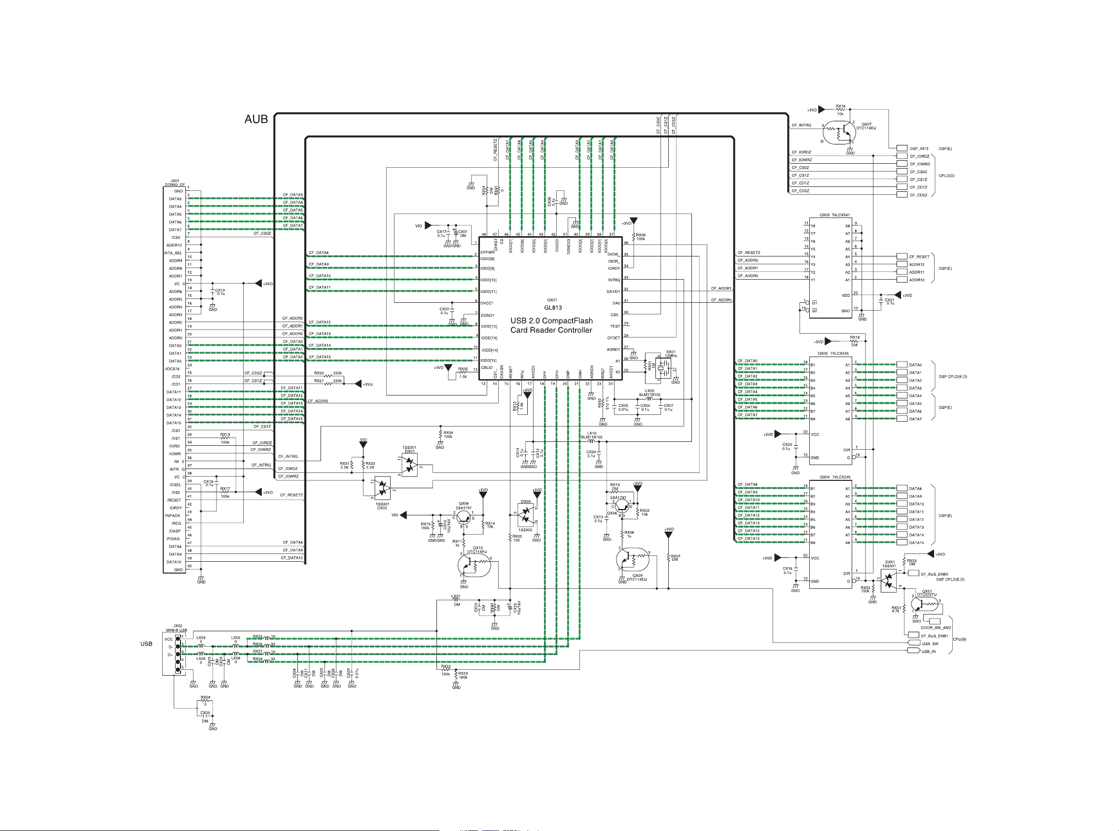
PM01 (C) USB & DATA BUFFER
WA01BS101*
19 20
Page 18
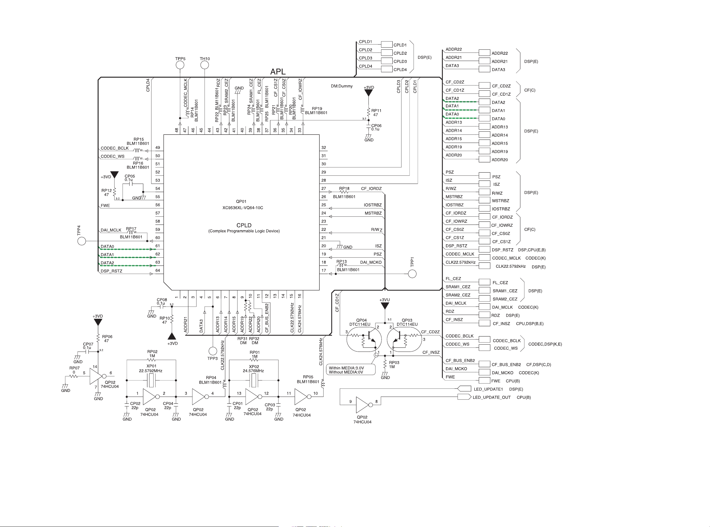
PM01 (D) CPLD
WI01BS101*
2221
Page 19
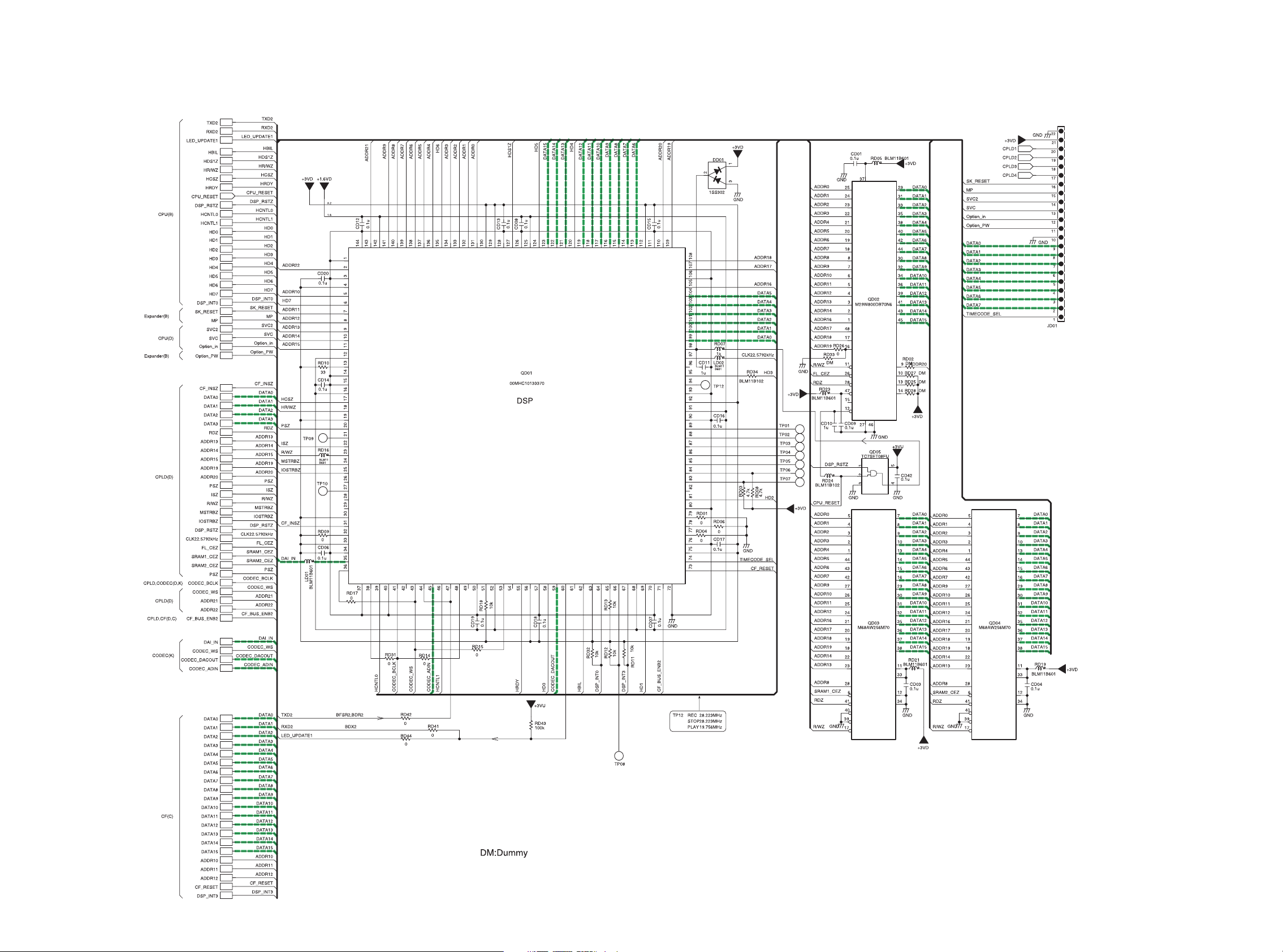
PM01 (E) DSP
WI01BS101*
23 24
Page 20
MIC/LINE INPUT
Rch
MIC/LINE INPUT
Lch
Lch Invert
GND
Lch Normal
Rch Invert
GND
Rch Normal
+48V
(P001)
NC3FAH2
122
NC3FAH2
122
JA01
1
2
3
4
5
6
7
JA03
3
JA02
3
1
3
G
4
1
3
G
4
+48V
DM
GND
RA91
47k
QA92
2C
2SC3324
B
1E
10k
RA94
GND GND
WI01BS103*
GND
RA24
3
RA93
10k
CA50
DM
CA49
DM
RA17
10k
GND
RA27
10k
RA26
10k
GND
RA28
10k
QA93
DTA144TE
231
GND
GND
GND
RA29
47(1/10W)
RA31
47(1/10W)
RA30
47(1/10W)
RA32
47(1/10W)
2
1
GND
RA74
6.8k 1/2W
RA72
6.8k 1/2W
RA75
6.8k 1/2W
RA73
6.8k 1/2W
31
31
31
31
+7V
RA92
10k
QA91
DTC114EU
PM01 (F) MIC AMP. BLOCK 1
CA74
10/63V
CA72
10/63V
CA75
10/63V
CA73
10/63V
CA76
220u/63V
GND
GND
GND
RA76
DM
JA04
+48V
7
Rch Normal
6
5
4
3
2
1
GND
Rch Invert
Lch Normal
GND
Lch Invert
WA09
Int.MIC
PCB SYM PM01
2
DA01
02CZ6.2Z
RA20
2.2k
RA33
220k
31
DA03
RA21
02CZ6.2Z
DA05
02CZ6.2Z
DA07
02CZ6.2Z
DA02
02CZ6.2Z
DA04
DA06
DA08
RA35
220k
RA34
220k
RA36
220k
RA18
220
RA16
2.2k
RA22
220
RA23
220
PHAN_SW
220
RA19
2.2k
RA15
2.2k
+7V
RA71
10k
2
2
31
2
2
31
02CZ6.2Z
2
2
02CZ6.2Z
31
02CZ6.2Z
2
3
Mic/Line_A
QA01
4
Y3
2
Y2
5
Y1
3
1
Y
Y0
GND
11
X3
15
X2
14
X1
12
X0
GND
9
B
10
A
6
INH
GND
For PHANTOM MUTE and Attenation(-20dB)
4
Y3
2
Y2
5
Y1
1
Y0
GND
11
X3
15
X2
14
X1
12
X0
GND
9
B
10
A
6
INH
GND
+7V
RA70
10k
QA10
DTC114EU
2
1
GND
74HC4052
QA02
74HC4052
GND
GND
RA37
220k
GND
10u/16V
+7V
13
X
16
Vcc
CA16
0.1u
8
CA18
7
VEE
-7V
3
Y
RA38
220k
GND
+7V
13
X
RA40
220k
16
Vcc
CA17
0.1u
8
CA19
7
0.1u
VEE
-7V
3
10u/16V
CA22
RA39
GND
0.1u
CA20
220k
GND
GND
GND
CA21
10u/16V
CA23
10u/16V
RE01
22k
RE21
22k
RE41
22k
RE61
22k
WI01BS101*
+7V
RA01
10k
RA02
2.2k
3
B
3
B
CE41
3
B
3
B
JA05
CE01
RE64
RE24
CE21
RE44
CE61
CA01
10u/10V
GND
1
2
RE04
1.2k
31
2
DE01
1.2k
31
2
DE21
1.2k
31
2
DE41
1.2k
31
2
DE61
MS01
KUC21
WA12
+7V
RE03
1.2k
G1 G2
5
GND
RE23
1.2k
G1 G2
5
GND
RE43
1.2k
G1 G2
5
GND
+7V
RE63
1.2k
G1 G2
5
GND
RE08
2200p
100
D1 D2
2SK3320
QE01
2
S
RE05
10
2C
QE02
+7V
1E
RE06
100
-7V
RE28
2200p
100
D1 D2
2SK3320
QE21
2
S
RE25
10
2C
QE22
1E
RE26
100
-7V
+7V
2200p
RE48
D1 D2
100
2SK3320
QE41
D1 D2
QE61
S
2
RE45
10
2C
QE42
1E
RE46
100
-7V
2200p
RE68
100
2SK3320
S
2
RE65
10
2C
QE62
1E
RE66
100
-7V
CA03
RA14
100
10u/10V
RA03
CA02
0.1u
GND
GND
DM
RE10
12k
RE07
CE02
100p
4
RE09
5.6k
100
RE02
RA77
CE03
31
100u/16V
GND
DM
DM
RA41
GND
12k
RE27
CE22
100p
4
RE29
5.6k
100
RE22
CE23
100u/16V
RA78
31
GND
DM
CA47
DM
RA43
RE30
DM
GND
RE47
12k
CE42
100p
4
RE49
5.6k
100
RE42
CE43
100u/16V
31
GND
DM
RA42
DM
RE50
RE67
12k
100p
CE62
4
RE69
5.6k
RE62
100
CE63
100u/16V
31
GND
DM
RA44
RE70
GND
DM
10
DM
CA45
DM
GND
6
5
RA53
DM
GND
2
34
RA54
GND
RA79
DM
DM
CA46
RA80
DM
RA56
DM
CA48
CA24 DM
+7V
6.8
NJM2068V
RA48
CA27 DM
NJM2068V
-7.2
DM
-7V
GND
DM
GND
RA45
DM
2
3
DM
RA04
QA03
6
5
RA55
10k
CA30
0.1u
0.1u
CA34
DM
8
-7.2
GND
GND
7
QA03
1
GND
RA47
DM
CA26
DM
6.8
NJM2068V
QA04
RA50
DM
CA29
DM
QA04
NJM2068V
CA35
-7V
+7V
CA32
0.1u
8
GND
1
4
0.1u
GND
7
6
5
2.2k
RA51
GND
2
34
RA52
2.2k
GND
4.7k
RA57
CA36
DM
4.7k
RA60
4.7k
RA59
CA37
DM
4.7k
RA61
GND
CA25 47p
+7V
NJM022V
NJM022V
GND
RA64
4.7k
RA05
2
3
470
RA46
10k 1%
CA31
0.1u
8
GND
QA05
RA49
10k 1%
CA28
47p
1
QA05
CA33
0.1u
GND
-7V
RA66 4.7k
CA39 47p
CA42
0.1u
6
NJM2068V
5
RA63
4.7k
RA68 4.7k
CA41 47p
4
CA43
0.1u
-7V
+7V
RA07
8.2k
7
RA58
4.7k
CA38
RA62
4.7k
+7V
8
GND
7
QA06
1
NJM2068V
QA06
GND
658
GND
DM
RA65
4.7k
GND -7V
CA08
10u/10V
CA09
10u/10V
RA11
100k
NJM2068V
RA81
470
2
1
DTC323TU
GND
RA67 4.7k
CA40 47p
2
QA07
NJM2068V
3
GND
47pCA04
QA07
RA10
100k
10kRA06
CA05
0.1u
QA21
4
CA44
0.1u
GND
LCH
RCH
GND
CA06
10u/10V
7
+7V
QA22
DTA114EU
1
3
2
RA82
100k
-7V
CA07
1
10u/10V
RA09
100k
GND
GND
RA69
RA25
10
RA08
100k
GND
3
10Pin 9Pin
RA13
100k
1k
H:MUTE ON
3
Y
+7V
13
X
16
8
7
-7V
CA10
0.1u
CA11
0.1u
QA23
DTA144TE
231
GND
GND
INTMIC_MUTE
MIC_L
MIC_R
G
G
QA13
DTC323TU
2
1
GND
Dual Level Mono
Int/Mic
4
2
5
1
11
15
14
12
9
10
6
GND
QA08
74HC4052
Y3
Y2
Y1
Y0
X3
X2
X1
X0
B
A
INH
3
Vcc
GND
VEE
OUTPUT
L
H
RA12
100k
L
H
X0Y0
L
X1Y1
L
H
X2Y2
X3Y3
H
+7V
QA11
DTC114EU
2
1
GND
QA12
DTC114EU
2
1
GND
3
3
INT MIC
STEREO
DUAL MONO
NOT USE
INT/EXT
(CPU)
DUAL_MONO
(CPU)
PHANTOM_MUTE
ATT_20
(CPU)
(LID SW)
B
B
B
B
To Chassis
RI(*1)
0.1u
CA12
GND
*1:Chassis of Right the Interior
DM:Dummy
2625
Page 21

PM01 (G) MIC AMP. BLOCK 2
WI01BS101*
27 28
Page 22

PM01 (H) ALC/LIMITER AMP. BLOCK
WI01BS101*
3029
Page 23

(PW06)
PM01 (J) Analog Output BLOCK
WI01BS101*
(P001)
PHONES
(PH01)
31 32
Page 24

PM01 (K) CODEC
WI01BS101*
3433
Page 25

PF01 (L) LCD UNIT
WI01BS102*
VF01
LCD UNIT
JF01
19FMN-BMTTN
1
2
3
4
5
6
7
8
9
10
11
12
13
14
15
16
17
18
19
+5VD
+3VL
GND
LRESET
E
RW
RS
DB4
DB5
DB6
DB7
KEY_IN6
KEY_IN7
SCAN0
SCAN1
SCAN2
RECLED
BLIGHT
TOTAL
RE
TRACK
M
A
RK
5.2
C
GND
TRACK
TIME
REMAIN
kbps
+5VD
LF01
CF23
DM
GND
DF02
31
1SS301
KEY LOCK
REC0RDING LED
L:REC LED OFF
H:REC LED ON
A-B
3.3
0
DB4
DB5
DB6
DB7
DF09
2
231
SF01
REC-PAUSE
DTC123JE
3
H:BACK LIGHT ON
L:BACK LIGHT OFF
kHz
A
PM
+3VF
CF20
470p
2
31
1SS301
4
5
3
12
SF05
CF03
0.1u
GND
+5VD
DF01
RF05
RF06
1k
DM
QF02
2
1
GND
L
-
40 20 12 6 2 0
dB
R
M
INT
MIC
LINE
CF19
470p
GNDGND
DF10
2
31
1SS301
12
SF04
DISPLAY
NSCW215
3
DF05
NSCW215
S.SKIP
CF21
470p
GND
GND
DF07
2
31
4
3
DF03
DTC123JE
1SS301
5
12
SF03
LIGHT
CF01
0.1u
GND
+5VD
RF12
100
QF04
2
1
GND
BackLight LED
+5VD +5VD
RF11
100
NSCW215
3
DF06
CF18
470p
4
3
CF02
0.1u
5
GND
DF04
NSCW215
QF06
DTC123JE
OVER
-
dB
DF08
2
31
1SS301
231
REC/MARK
+5VD
RF04
100
2
1
GND
RF03
100
123456789101112131415161718192021222324252627282930313233343536373839404142434445464748495051525354555657585960616263646566676869 70 71 72 73 74 75
COM1
COM2
COM3
COM4
COM5
COM6
COM7
COM9
COM10
COM11
COM12
COM13
COM14
COM15
SEG1
SEG2
SEG3
SEG4
SEG5
SEG6
SEG7
SEG8
SEG9
SEG10
SEG11
SEG12
SEG13
SEG14
SEG15
SEG16
SEG17
SEG18
SEG19
SEG20
SEG21
SEG22
SEG23
SEG24
SEG25
SEG26
SEG27
SEG28
SEG29
SEG30
SEG31
SEG32
SEG33
SEG34
SEG35
SEG36
SEG37
SEG38
SEG39
SEG40
SEG41
SEG42
SEG43
SEG44
SEG45
SEG46
SEG47
SEG48
SEG49
SEG50
SEG51
SEG52
SEG53
SEG54
CF14
470p
1
2
GND
GNDGND
ADJ MEASURE
SPEC. DC7V+-0.1V
DB6
DB5
DB4
CF13
470p
CF12
1000p
SF02
COM9
COM10
COM11
COM12
COM13
COM14
COM15
SEG1
SEG2
SEG3
SEG4
SEG5
SEG6
SEG7
SEG8
SEG9
SEG11
SEG10
SEG12
SEG13
SEG14
SEG15
CF11
1000p
GNDGND
GND
CF17
470p
GND
1000p
GND
1u
SEG17
SEG18
SEG19
SEG20
SEG21
SEG22
SEG23
SEG24
SEG25
SEG26
SEG27
SEG28
SEG29
SEG30
SEG31
SEG32
SEG33
SEG34
SEG35
SEG36
SEG37
SEG38
SEG39
SEG40
SEG41
CF09
CF10
SEG16
76
77
78
79
80
81
82
83
84
85
86
87
88
89
90
91
92
93
94
95
96
97
98
99
100
12345678910111213141516171819202122232425
SEG42
SEG43
SEG44
SEG45
SEG46
SEG47
SEG48
SEG49
FRONT uP
SEG50
SEG51
SEG52
QF01
NJU6469
SEG53
SEG54
SEG55
SEG56
SEG57
SEG58
SEG59
SEG60
COM7
COM6
COM5
COM4
DB7
CF16
470p
GND
51525354555657585960616263646566676869707172737475
50
49
48
47
46
45
44
43
42
41
40
39
38
37
36
35
34
33
32
31
30
29
28
27
26
COM3
CF04 4.7u/25V
CF05 4.7u/25V
CF07
47u/16V
GND
RF07
+3VF
DM
CF08
0.1u
CF15
470p
ADJUSTING POINT
RF01
1
20k
RF02
15k
COM1
COM2
JF02
B2B-PH-SM3
GNDGND
23
CF06
10u/16V
SEG55
SEG56
SEG57
SEG58
SEG59
SEG60
DM:Dummy
3
QF05
DTC123JE
2
1
GND
BackLight LED
2
3
1
QF07
DTC123JE
GND
35 36
Page 26

PF02 (M) KEY BLOC
WG01BS201*
RAW
DF60
654
1SS176
SF57
RAW
123
OFF/ON
INPUT
DF59
654 +7V
1SS176
SF55
INPUT
123
CHANGE/LOCK
PRE REC
DF58
1SS176
654
SF56
OFF/ON
PRE REC
DF51 1SS176
654
SF51
EDL PLAY
123
EDL PLAY
123
ANALOG OUT
DF52
1SS176
678910
SF52
ANALOG
OUT
DF53
12345
L/ST/R
1SS176
REPEAT
6 78910
12345
OFF/1/ALL
DF54
1SS176
SF53
REPEAT
DF55
1SS176
ALC/LIMITER/MANUAL
DF56
6 78910
12345
1SS176
SF54
LEVEL
CONT
DF57
1SS176
ALC/LIMITER/MANUAL
EDIT
SF59
12
EDIT
1SS176
A-B
SF61
12
A-B
SELECT
SF60
12
SELECT
SF65
12
MARK-D
12
MARK-U
12
MARK_D
MAEK_U
SF64
SF58
MENU
1SS176
1SS176
1SS176
DF62
DF64
1SS176
DF63
DF67
1SS176
DF68
DF61
FF
SF62
12
FF
1SS176
NEXT
SF68
12
NEXT
PREV
SF69
12
PREV
REW
SF63
12
REW
STOP
SF66
12
STOP
PLAY
SF67
12
PLAY
DF69
DF72
1SS176
DF66
1SS176
DF70
1SS176
DF65
1SS176
DF71
1SS176
GND
SF70
MIC ATT
0dB -20dB
654
123
RF51
10k
CF54
470p
+7V
CF53
470p
ANC
BPF FLAT HPF
1234 5
678910
CF51
CF52
470p
470p
GND
SF71
ANC
ATT_20
FLAT
HPF
BPF
SCAN3
SCAN2
SCAN1
SCAN0
KEYIN5
KEYIN4
KEYIN3
KEYIN2
KEYIN1
KEYIN0
JF51
16FMN-SSTK
TO
MAIN
16
15
14
13
12
11
10
9
8
7
6
5
4
3
2
1
GND
3837
Page 27

10. PARTS LOCATION
PC01
DU02 A3
JU05 A2
RU11 A2
RU12 A3
SU02 A2
PF01 A
PF01 B
CF01 A7
CF02 A8
CF03 B6
CF14 B7
CF16 B7
CF17 B8
CF18 B7
CF19 B7
CF20 B7
DF01 B7
DF03 A6
DF04 B6
DF05 B6
DF06 B6
DF07 A7
DF08 B7
DF09 B7
CF04 B2
CF05 B3
CF06 B3
CF07 B6
CF08 B4
CF09 A8
CF10 B8
CF11 A8
CF12 B8
CF13 A7
CF15 A7
CF21 A7
CF23 A8
DF02 A8
JF01 B7
JF02 B6
LF01 A8
DF10 A7
RF03 B6
RF04 A6
RF11 B6
RF12 A6
SF01 A8
SF02 B8
SF03 A7
SF04 A6
SF05 B6
VF01 A1
QF01 A4
QF02 B8
QF04 A6
QF05 B6
QF06 A6
QF07 B6
RF01 B2
RF02 B2
RF05 B7
RF06 B7
RF07 B3
PH01
J304 A1
J308 A2
U1 B2
CU51 B1
PS01PP01
JU04 A1
SU01 A1
JU10 A2
SU03 A2
U4 A1
39 40
PW06
J303 A1
R378 A1
Page 28

C301 D8
C302 E8
C303 E8
C304 D8
C305 D8
C312 E8
C314 E8
C315 E8
C316 E8
C317 E8
C318 E8
C319 F8
C324 E8
C325 E8
C327 E8
C328 F9
C332 F8
C333 F8
C338 E8
C340 E7
C344 E9
C345 E9
C354 D7
C355 D7
C356 D7
C407 D9
C408 D9
C412 D9
C414 D8
C424 D8
C426 C8
C428 C8
C431 C9
C439 B2
C801 G2
C802 D7
C803 E5
C804 E6
C806 E6
C807 F6
C808 E4
C809 E6
C810 E4
C811 F5
C812 E7
C813 F6
C815 D4
C816 F5
C826 E4
C829 F6
C838 F4
C840 E6
C843 E7
C844 E4
C847 F4
C848 F6
C855 E3
C856 F5
C859 E5
C862 D4
C863 E4
C864 E5
CA01 G9
CA02 G9
CA03 G9
CA04 F11
CA05 F11
CA06 F11
CA07 F11
CA08 F10
CA09 F9
CA12 G11
CA16 G10
CA17 G10
CA18 G11
CA19 G10
CA36 F10
CA37 F9
CA38 F11
CA39 F10
CA40 F11
CA41 F9
CA42 F10
CA43 F10
CA44 F11
CB05 E11
CB06 E10
CB07 D9
CB08 E11
CB09 E11
CB10 E11
CB11 E11
CB12 E11
CB13 E11
CB14 E11
CB15 E11
CB20 E10
CB21 E9
CB22 F10
CB23 F10
CB26 E10
CB28 E10
CB29 E10
CB30 E10
CB31 E10
CB32 E10
CB33 E10
CB41 E10
CB42 E9
CB65 D11
CB66 D11
CC03 C10
CC04 C11
CC05 C11
CC06 C11
CC07 C10
CC08 C11
CC13 D10
CC15 D10
CC17 D10
CC18 D10
CC19 D10
CC20 C10
CC21 C10
CC22 C10
CC23 C10
CC24 C10
CC25 C10
CC26 C10
CC28 C10
CC29 C10
CC30 C11
CC31 B10
CC32 B11
CC34 D10
CC35 D10
CC38 C10
CC71 B10
CC72 A11
CD01 C6
CD03 D5
CD06 B4
CD07 B5
CD11 C6
CD14 C4
CD16 C6
CD17 B6
CD18 B5
CD19 B5
CD20 C4
CD42 C6
CE01 F11
CE02 F11
CE21 F10
CE22 F11
CE41 F10
CE42 G10
CE62 F9
CP07 C7
CP08 C7
CU07 B8
CU08 A8
CU14 C8
CU15 C9
CU26 B3
CU27 B3
CU33 B8
CU52 C11
CX03 F1
CX18 D3
D302 E8
D303 E8
D304 F8
D305 F8
D806 E6
D810 D3
D815 G2
D816 H2
D817 E5
D818 F3
D820 E5
D821 F3
D822 F2
D824 D3
DA03 G11
DA04 G10
DA05 G10
DA06 G10
DB61 D10
DB62 D9
DC01 C10
DC02 C10
DC73 D11
DE21 F11
DE61 F9
DU06 C8
DX51 B4
F801 G2
J301 B3
J302 E7
J305 E9
J309 A3
J401 B1
J801 G1
J806 G2
J810 C4
JA01 H10
JA05 G9
JC01 B11
JD01 D6
JU01 G11
JU03 B3
JU06 C9
JU07 C8
JU08 A9
JU09 B2
JU11 A11
JU21 B10
JX01 D2
JX02 F1
L301 D9
L302 E8
L306 E9
L307 E8
L356 B3
L401 C2
L403 B2
L404 D8
L801 E3
L802 E7
L804 E4
L805 D4
L807 E4
L809 F6
L812 E4
L813 E6
LD01 B4
LD02 C6
LU04 B3
LU05 B8
PM01 A
LU06 B8
LU07 B8
LU08 A8
LU09 A8
LU10 A8
LU11 A8
LU12 A8
LU22 C8
LU24 A9
LU26 A9
LU33 A9
LU36 A9
LU38 A9
LX03 F1
Q303 E8
Q310 D8
Q316 F8
Q321 E9
Q322 E9
Q328 E8
Q329 F9
Q330 E8
Q333 F9
Q334 F9
Q351 D7
Q401 D8
Q402 D8
Q403 D8
Q804 F4
Q806 E4
Q807 E5
Q810 F6
Q816 F4
Q823 G2
Q827 C4
Q828 G2
Q831 E4
Q837 F5
Q842 F5
Q849 G2
Q851 F5
Q852 E5
Q853 F3
Q854 F2
Q855 E4
Q856 E3
Q858 E4
Q859 E5
Q860 E6
Q861 E5
Q863 D5
Q941 F4
Q942 F7
QA01 G11
QA02 G10
QA06 F10
QA07 F11
QA10 G11
QA11 E11
QA12 E11
QA22 F11
QA23 E11
QB01 E10
QB02 E11
QB03 E10
QB04 E10
QB05 E10
QB06 E10
QB08 E10
QC01 C11
QC03 D10
QC04 D10
QC05 C10
QC12 C10
QC13 D10
QC15 C10
QC16 D9
QC17 D9
QC31 C11
QC32 C11
QC73 D10
QD01 C5
QD03 D5
QD05 C6
QE01 F11
QE21 F10
QE22 F10
QE41 F10
QE42 F10
QE62 F10
QP01 C7
QP02 C7
QP03 C3
QP04 D3
QU01 B9
QX51 B4
R301 D8
R302 D8
R303 D8
R304 E8
R305 E8
R306 E8
R307 E8
R308 E8
R311 E9
R314 E8
R322 E8
R323 E8
R324 F8
R325 E9
R326 E9
R327 E8
R330 E8
R331 E8
R333 D8
R335 E8
R336 E8
R340 F9
R344 F9
R347 F8
R348 F9
R358 E9
R359 E9
R366 D8
R368 E9
R370 E9
R372 D7
R377 D7
R381 F9
R382 F9
R386 A3
R387 A3
R388 A3
R395 F7
R396 F8
R405 D9
R408 D9
R413 D8
R414 D9
R415 D8
R416 D8
R417 D9
R418 D9
R429 D8
R430 D8
R432 D8
R433 D8
R434 D8
R435 C8
R436 C8
R437 D8
R438 D8
R446 C7
R447 C7
R448 C7
R452 C8
R459 C8
R460 C8
R461 C9
R801 F1
R803 F1
R804 F2
R805 F3
R806 F1
R807 F3
R815 F2
R819 F5
R821 F5
R824 F2
R827 E4
R829 D4
R832 F5
R835 E3
R837 F5
R838 E3
R839 F5
R840 E4
R844 E5
R846 E4
R847 F3
R848 F4
R851 F2
R854 E6
R857 E7
R859 C4
R862 E7
R863 D4
R864 D3
R865 G2
R868 G2
R869 E6
R874 F2
R876 F2
R886 E6
R890 F2
R891 F2
R893 G2
R899 E7
R906 E7
R911 E4
R925 E5
R926 E5
R927 E3
R929 C4
R931 D4
R935 E5
R936 E5
R937 E5
R938 E5
R939 E3
R940 D5
R941 E3
R942 F3
R944 E7
R945 E5
R946 D5
R947 F4
RA01 G9
RA02 G9
RA03 G9
RA04 G9
RA05 F11
RA06 F11
RA07 F11
RA08 F11
RA09 F11
RA10 F10
RA11 F9
RA12 E11
RA13 E11
RA14 G9
RA15 G10
RA16 G10
RA17 H11
RA19 G10
RA20 G11
RA24 H10
RA25 F11
RA26 H10
RA27 H10
RA28 H10
RA57 F10
RA58 F11
RA59 F9
RA60 F10
RA61 F9
RA63 F10
RA64 F10
RA66 F10
RA67 F10
RA68 F9
RA70 G10
RA71 G10
RA82 F11
RB08 E11
RB09 E11
RB11 E11
RB12 E11
RB13 E11
RB14 E10
RB23 E11
RB24 E9
RB38 E9
RB39 F9
RB40 E9
RB41 E10
RB42 E9
RB43 E10
RB44 E9
RB45 E11
RB52 E10
RB74 E11
RB77 E10
RB78 E9
RB91 E10
RB92 E9
RC03 C10
RC04 C11
RC05 C10
RC06 C11
RC07 C10
RC08 C11
RC11 D10
RC13 D10
RC15 D10
RC21 D11
4241
RC23 D10
RC25 D10
RC27 D10
RC28 D10
RC30 C10
RC36 D10
RC37 D10
RC38 C10
RC40 C10
RC41 C10
RC42 C10
RC43 C10
RC44 C10
RC46 C9
RC56 C10
RC61 C10
RC63 C10
RC73 D9
RC76 D10
RC87 C10
RC88 C11
RC93 C10
RC94 C10
RD01 B6
RD03 B6
RD04 B6
RD05 C6
RD06 B6
RD07 C6
RD08 B6
RD09 B4
RD10 C4
RD16 B4
RD21 D4
RD24 C6
RD34 C6
RD43 C6
RE01 G11
RE02 F11
RE05 F11
RE08 F11
RE09 F11
RE10 F10
RE22 G11
RE25 F10
RE27 F10
RE28 F10
RE29 F11
RE30 G10
RE41 G10
RE42 G10
RE45 F10
RE46 F10
RE48 F10
RE49 G10
RE66 F10
RE67 F9
RE69 F9
RP03 C3
RP06 C7
RP10 C7
RP13 C7
RP15 D6
RP16 D6
RP17 C6
RP19 D6
RP20 D6
RP21 D6
RP22 D6
RP23 D6
RP24 D6
RP25 D6
RP31 C7
RP32 C6
RU02 A11
RU05 A11
RU08 A11
RU14 B3
RU16 A11
RU21 A11
RU23 C9
RU26 G10
RU28 A11
RU36 B6
RU37 D7
RU38 D7
RU39 C8
RU41 B4
RU61 B7
RU62 B7
RU63 B8
RU64 B8
RU65 B8
RU66 B8
RU92 B7
RU93 B8
RX09 F1
RX20 D3
RX21 E3
RX51 B4
RX52 B3
RX53 B4
SU11 H10
T2 C9
TH10 D6
XP01 C7
XP02 B7
XU01 C9
Page 29

C306 E8
C307 E8
C308 F9
C309 E8
C310 E8
C311 F8
C320 E9
C321 D8
C322 E8
C323 F9
C326 F9
C329 F8
C330 F8
C334 E7
C336 F8
C337 F8
C342 E9
C343 E9
C346 E9
C347 E9
C348 E8
C349 E9
C350 E8
C351 E8
C352 B3
C353 E8
C357 A3
C358 A3
C401 D9
C402 C9
C403 D8
C404 C9
C405 D9
C406 D9
C409 D8
C410 C8
C411 C8
C413 D8
C415 D7
C416 D8
C417 D8
C418 D8
C419 D9
C420 D9
C421 D9
C422 C9
C423 C9
C425 D8
C427 C8
C429 D8
C430 C7
C432 B2
C433 B2
C434 B2
PM01 B
C435 C1
C436 C2
C437 B2
C438 C2
C440 B2
C441 C2
C442 C2
C443 C2
C451 C9
C452 C9
C453 D8
C454 D9
C805 E4
C814 E7
C817 F5
C818 F6
C819 E6
C820 F6
C821 E6
C822 E6
C823 E7
C824 D7
C825 E4
C827 E7
C828 E5
C830 F7
C831 D7
C832 F4
C833 F4
C834 E4
C835 E4
C836 E3
C837 E4
C839 E6
C841 E7
C842 E3
C845 F6
C846 E7
C849 E6
C850 E4
C851 E4
C853 E6
C854 E3
C857 H2
C858 E4
C860 B9
C861 B9
C941 F4
CA10 F11
CA11 E11
CA20 G11
CA21 G10
CA22 G10
CA23 G10
CA24 F10
CA25 F11
CA26 F10
CA27 F10
CA28 F11
CA29 F9
CA30 F10
CA31 F11
CA32 F9
CA33 F11
CA34 F10
CA35 F9
CA45 F10
CA46 F9
CA47 F10
CA48 G9
CB01 E10
CB02 E11
CB03 E11
CB04 D11
CB16 E11
CB17 E11
CB18 F10
CB19 F9
CB24 E10
CB25 E10
CB27 E10
CB34 E10
CB35 E10
CB36 E10
CB37 E9
CC01 B11
CC02 B11
CC11 B10
CC12 B10
CC14 D10
CC16 D9
CC27 C10
CC33 C10
CC36 C10
CC37 C11
CC39 C11
CC40 D10
CC41 D10
CC42 C11
CC43 C11
CD04 D5
CD08 C5
CD09 B5
CD10 C4
CD12 C5
CD13 C5
CD15 C5
CE03 G11
CE23 G11
CE43 G10
CE61 G9
CE63 G9
CP01 B7
CP02 C7
CP03 B7
CP04 C7
CP05 D7
CP06 D7
CU02 A10
CU03 A11
CU04 A11
CU05 A11
CU06 A11
CU09 B10
CU10 B8
CU11 B8
CU12 C9
CU13 C8
CU16 C8
CU17 B9
CU18 B8
CU19 B8
CU20 A8
CU21 A8
CU22 A8
CU23 A8
CU24 A8
CU25 A8
CU28 C9
CU31 B9
CU32 B9
CU37 B9
CX01 D2
CX02 C1
CX04 D1
CX05 D1
CX06 D1
CX07 D1
CX08 E2
CX09 G1
CX10 E1
CX11 E1
CX12 D1
CX13 E2
CX14 D1
CX15 E2
CX16 D3
CX17 D2
CX19 E3
CX20 D3
CX21 D3
CX22 E2
CX23 F1
CX24 F1
CX25 E1
CX26 E2
CX34 C1
D301 E7
D801 F2
D802 F5
D803 F5
D804 G2
D805 F3
D807 E4
D808 F6
D809 E7
D811 G2
D812 G2
D813 F4
D814 H2
D819 E7
D823 E5
DA01 G11
DA02 G10
DA07 G10
DA08 G10
DC03 C10
DC04 D10
DC05 C11
DC06 B11
DC07 C10
DC71 B11
DC72 B11
DC74 D11
DD01 B6
DE01 F11
DE41 F10
DU01 A11
DU03 B12
DU04 B10
DU05 B6
DU07 A8
DU08 F9
DX01 C3
DX02 C2
DX03 D1
L357 A4
L358 A3
L405 C1
L406 B1
L407 C2
L408 B2
L803 E4
L806 F6
L808 E6
L810 E6
L811 E6
L814 E4
LU02 B9
LU03 A11
LU13 C9
LU14 C9
LU15 C9
LU16 C9
LU17 C9
LU18 C8
LU19 C8
LU20 C8
LU21 C8
LU23 A9
LU25 A9
LU30 A9
LU34 A9
LU37 A9
LU41 A9
LU42 A9
LU43 A9
LX01 E1
LX02 D1
LX04 F1
LX05 F1
LX06 F1
LX10 D1
Q301 E9
Q302 E8
Q304 F9
Q305 F8
Q306 E8
Q307 E9
Q308 E8
Q309 E7
Q311 E8
Q312 E8
Q313 E8
Q314 E8
Q315 F8
Q317 F8
Q318 F8
Q319 E9
Q320 E9
Q323 E8
Q324 F8
Q327 E8
Q331 E8
Q332 D8
Q404 C2
Q405 D9
Q801 G2
Q802 F2
Q803 E4
Q805 E6
Q808 D4
Q809 E6
Q811 E4
Q812 F5
Q813 E5
Q814 F3
Q815 F2
Q817 F4
Q818 E7
Q819 F6
Q820 E4
Q821 F4
Q822 E7
Q824 F3
Q825 F3
Q826 E7
Q829 E5
Q830 F1
Q832 F2
Q833 G2
Q834 F3
Q835 F7
Q836 E5
Q838 F4
Q839 F4
Q840 F5
Q841 H2
Q843 E6
Q844 F5
Q845 H2
Q846 H2
Q847 E4
Q848 E5
Q850 F2
Q857 B10
Q862 G2
Q864 F7
QA03 F10
QA04 F9
QA05 F11
QA08 E11
QA13 F11
QA21 F11
QA91 H11
QA92 H10
QA93 H10
QB07 E11
QB10 E10
QB11 D10
QB12 E9
QC02 B10
QC06 C11
QC10 D10
QC11 D10
QC14 D10
QC18 C10
QC19 C10
QC20 C10
QC21 C10
QC22 B11
QC23 C10
QC24 C10
QC33 C10
QC34 C10
QC35 C10
QC36 C10
QC39 C10
QC43 D10
QC44 C10
QC71 D11
QC72 D11
QD02 C5
QD04 D5
QE02 F11
QE61 G9
QU02 C8
QU03 B10
QU04 A11
QU05 B8
QU06 A10
QU07 A8
QU11 B9
QU12 A5
QU17 B10
QU18 A11
QU19 A11
QU20 A11
QX01 D2
QX03 D3
QX04 C3
QX05 D3
QX06 E2
QX07 E3
QX08 E2
QX09 E2
QX10 E2
R309 E8
R310 E8
R312 E9
R313 E8
R315 E8
R316 E8
R317 E8
R318 E8
R319 E8
R320 E8
R321 E8
R328 D8
R329 D8
R332 E8
R334 E8
R337 F9
R338 E8
R339 F9
R341 F8
R342 F9
R343 F8
R345 F8
R346 F9
R349 F8
R350 F7
R351 F8
R352 E9
R353 E9
R354 E8
R355 E9
R356 E9
R357 E9
R360 E9
R361 E9
R362 E9
R363 E9
R364 E8
R365 E9
R367 E9
R369 E9
R371 E7
R373 E9
R374 E9
R375 D8
R376 D8
R379 F8
R380 E8
R383 E8
R384 F8
R385 A4
R389 B3
R390 E7
R391 E9
R392 E9
R393 D8
R394 D8
R397 E8
R398 E8
R399 F8
R400 E7
R401 D9
R402 C9
R403 D7
R404 C9
R406 D8
R407 C9
R409 D9
R410 D8
R411 C9
R412 D8
R419 C2
R420 B2
R421 B2
R422 D8
R423 C2
R424 C2
R425 D8
R426 B2
R427 D7
R428 D8
R440 B2
R441 C2
R442 B2
R443 C7
R444 C7
R445 C7
R451 D8
R453 C8
R454 C8
R455 D8
R456 D9
R457 C8
R458 C9
R802 F3
R808 F3
R809 F2
R810 F2
R811 F3
R812 F4
R813 F4
R814 F3
R816 E3
R817 E6
R818 E5
R820 E5
R822 G1
R823 F4
R825 F2
R826 E6
R828 E4
R830 G2
R831 G2
R833 F4
R834 F7
R836 E6
R841 F1
R842 F2
R843 E6
R845 E4
43 44
R849 E6
R850 E6
R852 F5
R853 E5
R855 F6
R856 E4
R858 E7
R860 D3
R861 E6
R866 E5
R867 F7
R871 E3
R872 F5
R873 F6
R875 G2
R878 E6
R879 H2
R880 D6
R882 E7
R883 E6
R884 F6
R885 F5
R887 G1
R888 F3
R892 E7
R894 E4
R895 E4
R896 D4
R897 G2
R898 F6
R900 F5
R901 F2
R902 E5
R903 E5
R904 F6
R905 E7
R907 F5
R908 F4
R910 F5
R912 E7
R913 E7
R914 E6
R915 E4
R916 E5
R917 F6
R918 E5
R920 F4
R921 F4
R922 F4
R923 E4
R924 E6
R928 B10
R930 F5
R932 E4
R933 E5
R934 E5
R943 E7
RA18 G10
RA21 G11
RA22 G10
RA23 G10
RA29 H11
RA30 H10
RA31 H10
RA32 H10
RA33 G11
RA34 G10
RA35 G10
RA36 G10
RA37 G11
RA38 G10
RA39 G10
RA40 G10
RA41 F10
RA42 F9
RA43 F10
RA44 G9
RA45 F10
RA46 F11
RA47 F10
RA48 F10
RA49 F11
RA50 F9
RA51 F11
RA52 F11
RA53 F10
RA54 F10
RA55 F10
RA56 F9
RA62 F11
RA65 F11
RA69 F11
RA77 F10
RA78 F10
RA79 F9
RA80 G9
RA81 F11
RA91 H10
RA92 H10
RA93 H10
RA94 H10
RB01 E10
RB02 E10
RB03 E11
RB04 E10
RB05 D11
RB06 E11
RB07 E11
RB10 E11
RB15 E11
RB16 E11
RB17 E11
RB18 E11
RB19 E10
RB20 E9
RB21 E10
RB22 E9
RB25 D10
RB26 E10
RB27 E10
RB28 E10
RB29 E10
RB30 E10
RB31 E9
RB32 E9
RB33 E10
RB34 E10
RB35 E10
RB36 E10
RB37 E10
RB46 E11
RB51 E10
RB73 D10
RB75 D11
RB76 D11
RC01 C10
RC02 C11
RC12 D10
RC14 D10
RC16 D10
RC17 D10
RC18 D10
RC19 D11
RC20 D10
RC22 D9
RC24 D9
RC26 D10
RC29 C10
RC31 C10
RC32 C11
RC33 C10
RC34 C10
RC35 D10
RC39 C10
RC45 C10
RC47 C10
RC48 C11
RC49 C10
RC50 C10
RC51 C10
RC52 C11
RC53 C10
RC54 C10
RC55 C9
RC57 B10
RC58 B10
RC59 C11
RC60 C11
RC62 D11
RC71 D11
RC72 D11
RC74 D11
RC75 D11
RC79 B11
RC80 B11
RC81 C10
RC82 C11
RC83 C10
RC84 C11
RC89 D10
RC90 D10
RC91 C10
RC92 C10
RD02 C4
RD11 B5
RD12 B5
RD13 B5
RD14 B5
RD15 B5
RD17 B5
RD18 B5
RD19 D5
RD23 B5
RD25 C4
RD26 C4
RD27 C4
RD28 C4
RD31 B5
RD32 B5
RD33 C4
RD41 B6
RD42 B6
RD44 B6
RE03 F11
RE04 F11
RE06 F11
RE07 F11
RE21 G10
RE23 F10
RE24 F10
RE26 F10
RE43 F10
RE44 F10
RE47 F10
RE50 F10
RE61 G10
RE62 G9
RE63 G9
RE64 G9
RE65 G9
RE68 G9
RE70 G9
RP01 B7
RP02 C7
RP04 C7
RP05 C7
RP07 C7
RP11 C7
RP12 C7
RP14 D7
RP18 C7
RU03 B9
RU04 B9
RU09 B10
RU10 B8
RU13 C8
RU15 A11
RU17 C8
RU18 B11
RU19 B10
RU20 A11
RU22 A11
RU24 G9
RU25 B9
RU27 C9
RU29 G10
RU30 C9
RU31 B9
RU32 B9
RU33 C9
RU34 C9
RU35 A8
RU40 G10
RU48 B7
RU49 B8
RU50 B7
RU51 A8
RU52 A7
RU53 B9
RU54 B8
RU55 B8
RU56 B10
RU57 B11
RU59 A11
RU68 B10
RU69 A10
RU71 B8
RU72 B8
RU73 B8
RU74 B8
RU75 B8
RU76 B8
RU77 B8
RU78 B8
RU79 C8
RU81 A8
RU82 A7
RU83 A8
RU84 B8
RU85 B8
RU86 C8
RU87 C8
RU88 C8
RU89 C8
RU90 C8
RU91 C8
RU99 A11
RX01 D2
RX02 D1
RX03 E2
RX04 C1
RX05 D2
RX06 D2
RX07 E2
RX08 F2
RX11 E1
RX12 D1
RX13 E2
RX14 E1
RX15 E2
RX16 E3
RX17 E3
RX18 D2
RX19 E3
RX22 E1
RX23 E1
RX24 C2
RX25 E2
RX26 E1
RX27 E2
RX28 E1
RX31 C3
RX32 C3
RX41 D2
RX42 D1
RX43 E1
XU02 A11
XX01 D2
Page 30

PF02
CF51 E1
CF52 D5
CF53 A2
CF54 A1
DF51 E3
DF52 E4
DF53 E3
DF54 E3
DF55 D4
DF56 D5
DF57 D5
DF58 D2
DF59 D2
DF60 E2
DF61 A2
DF62 C4
DF63 C2
DF64 C3
DF65 A4
DF66 B1
DF67 C3
DF68 C5
DF69 B5
DF70 B3
DF71 A4
DF72 B2
JF51 F2
RF51 E4
SF51 D3
SF52 E3
SF53 D3
SF54 D4
SF55 D2
SF56 D2
SF57 E2
SF58 A2
SF59 C4
SF60 C2
SF61 C2
SF62 B5
SF63 B3
SF64 C5
SF65 C3
SF66 A5
SF67 A3
SF68 B2
SF69 B1
SF70 E4
SF71 D4
U101 E1
U102 E2
U103 E3
U104 D4
U105 D4
U106 E4
U107 D4
U108 B5
US01 A2
US02 B4
US03 B4
US04 C5
P001 A
P001 B
CA72 B4
CA73 B4
CA74 A4
CA75 B3
CA76 B4
CJ03 B2
CJ04 A3
CJ08 B1
CJ09 B1
CJ10 B1
JA02 A4
JA03 A5
JA04 B5
JJ02 A2
JJ03 B3
JU12 B2
CA49 A4
CA50 A4
CJ01 A3
CJ02 A2
CJ05 B3
CJ06 B3
CJ07 B3
CJ11 A2
CJ12 A2
CJ21 A3
CJ22 A3
CU01 A1
LJ01 B2
LJ02 B2
LJ03 A2
LJ04 B2
JU13 A1
RJ11 B2
LU01 A1
QJ01 B3
QJ21 B3
QJ22 B3
RA72 B5
RA73 B5
RA74 B5
RA75 B5
RA76 B4
RJ01 A3
RJ02 A2
RJ03 B3
RJ04 B3
RJ05 A3
RJ06 A3
RJ07 B3
RJ08 B3
RJ09 B1
RJ10 B1
RJ12 B3
RJ13 A2
RJ14 A2
RJ15 B1
RJ21 A3
RJ22 A3
RU01 A1
RU06 A1
RU07 B1
RU58 A1
RU60 A1
P801
F802 B2
J802 B1
J803 A1
J804 B1
J805 A2
P802
J807 A1
J808 B1
J809 B2
P002
JU15 A1
JU16 A2
P003
JC02 A1
RC64 A1
U2 A2
4645
Page 31

11. MICROPROCESSOR AND IC DATA
QU01 : HD64F2328 (FRONT uP)
No port name I/O USE Sig. Name ACT INI PUP Description
1 Vcc - - +3.3V - - 2 PC0 I/O I/O HPI HD0 - L OFF
3 PC1 I/O I/O HPI HD1 - L OFF
4 PC2 I/O I/O HPI HD2 - L OFF
5 PC3 I/O I/O HPI HD3 - L OFF
6 VSS - Ground - - - Ground
7 PC4 I/O I/O HPI HD4 - L OFF
8 PC5 I/O I/O HPI HD5 - L OFF
9 PC6 I/O I/O HPI HD6 - L OFF
10 PC7 I/O I/O HPI HD7 - L OFF
11 PB0 I/O O I2C Bus SCL - H OFF Pull Up 22 k ohm
12 PB1 I/O I/O I2C Bus SDA - H OFF Pull Up 22 k ohm
13 PB2 I/O O USB SW - - OFF
14 PB3 I/O O CF ENABLE SW - - OFF
15 VSS I - Ground - - -
16 PB4 I/O O
17 PB5 I/O O
18 PB6 I/O O
19 PB7 I/O O CHARG TRI H L 20 PA0 I/O O S_MUTE H L OFF for DAC
21 PA1 I/O O PDN L H OFF for DI, DAC, ADC
22 PA2 I/O I DIR_INT0 - L OFF for DIT/DIR
23 PA3 I/O I DIR_INT1 - L OFF for DIT/DIR
24 VSS I - Ground - - 25 PA4 I/O O DIT_VIN - - OFF for DIT/DIR
26 PA5 I/O O XCTL0 - - OFF for DIT/DIR
27 PA6 I/O O XCTL1 - - OFF for DIT/DIR
28 PA7/IRQ7 I/O O BACKLIGHT H H OFF for LCD
29 P67 I/O I AC_IN H L 30 P66 I/O I RTC_INT H L 31 P65/IRQ1 I/O I Power SW H L 32 P64/IRQ0 I/O I REMOTE1 - H - Pull Up
33 Vcc - - +3.3V' - - 34 PE0 I/O I/O DB4 H L OFF for LCD
35 PE1 I/O I/O DB5 H L OFF for LCD
36 PE2 I/O I/O DB6 H L OFF for LCD
37 PE3 I/O I/O DB7 H L OFF for LCD
38 VSS I - Ground - - 39 PE4 I/O O LRESET H L OFF for LCD
40 PE5 I/O O RW H L OFF for LCD
41 PE6 I/O O RS H L OFF for LCD
42 PE7 I/O O E H L OFF for LCD
43 PD0 I/O O (L+R)/2 H L OFF
44 PD1 I/O O ST_MONO H L OFF
45 PD2 I/O O DUAL MONO H L OFF
46 PD3 I/O O INT/EXT H L OFF H: INT / L: EXT
47 VSS I - Ground - - 48 PD4 I/O O MIC/LINE H L OFF H: MIC / L: LINE
49 PD5 I/O O OUTPUT SEL 0 - L
50 PD6 I/O O OUTPUT SEL 1 - L
51 PD7 I/O O SP-MUTE H L
52 Vcc 53 P30/TXD0 I/O O PWM-MUTE H L
54 P31/TXD1 I/O O TXD For Flash Writing
55 P32/RXD0 I/O O DSP_SW (DOOR_SW) H L
56 P33/RXD1 I I RXD For Flash Writing
57 P34/SCK0 I/O I TRSTn
58 P35/SCK1 I/O I SCK For Flash Writing
59 VSS I - Ground - - - Ground
60 P60 I/O I TMS - - -
DV_SW
(DC/DC+3.3V/5V SW)
AV_SW
(DC/DC +-8V SW)
+48SW
(DC/DC +48V SW)
H L OFF
47
Page 32

No port name I/O USE Sig. Name ACT INI PUP Description
61 P61 I/O I TCK - - 62 P62 I/O I TDI - - 63 P63 I/O O TDO - - 64 P27 I/O O REC LEVEL 1 H L OFF
65 P26 I/O O REC LEVEL 0 H L OFF Man/Lim/ALC
66 P25 I/O I SVC
67 P24 I/O I SVC2
68 P23 I/O O SCAN3 L H OFF
69 P22 I/O O SCAN2 L H OFF
70 P21 I/O O SCAN1 L H OFF
71 P20 I/O O SCAN0 L H OFF
72
WDTOVF - - - - 73
74 NMI I I - - - - Pull Up
75
76 Vcc - - +3.3V - - 77 XTAL O O 24.576 MHz - - 78 EXTAL I I 24.576 MHz - - 79 VSS I - - - - - Ground
80 PF7 I I KEY_IN7 L H - Pull Up
81 Vcc - - +3.3V
82 PF6 I/O I KEY_IN6 L H - Pull Up
83 PF5 I/O I KEY_IN5 L H - Pull Up
84 PF4 I/O I KEY_IN4 L H - Pull Up
85 PF3 I/O I KEY_IN3 L H - Pull Up
86 PF2 I/O I KEY_IN2 L H - Pull Up
87 PF1 I/O I KEY_IN1 L H - Pull Up
88 PF0 I/O I KEY_IN0 L H 89 P50 I/O O LINE-MUTE H L 90 P51 I/O O HP-MUTE H L 91 P52 I/O O INTMIC-MUTE H L 92 P53 I/O O PHANTOM-MUTE - - OFF
93 ACVV I - +5V - - 94 Vref - Ground - - -
95 P40 I ADC
96 P41 I ADC LIMIT_CHK - - -
97 P42 I I
98 P43 I I HRDY - - 99 P44 I I CARD IN L H - Pull Up
100 P45 I I USB IN H L - CD1 & CD2 & USB1
101 P46 I ADC REMOTE2 - - 102 P47 I ADC BAT - - 103 AVSS I - Ground - - Ground
104 VSS I - - Ground
105 P17 I/O I Option IN
106 P16 I/O O HCNTL1 H H 107 P15 I/O O HCNTL0 H H 108 P14 I/O I Reserve
109 P13/TIOCD0 I/O I CARDLID_OPEN
110 P12/TIOCC0 I/O O PWM - L 111 P11/TIOCB0 I/O O REC LED H L - RED LED
112 P10/TIOCA0 I/O O HRESET# L H 113 MD0 I I Mode 7 - - - Pull Up
114 MD1 I I Mode 7 - - - Pull Up
115 MD2 I I Mode 7 - - - Pull Up
116 PG0 I/O O HBIL H L 117 PG1 I/O O HDS# L L 118 PG2 I/O O HRW# L L 119 PG3 I/O O HCS# L L 120 PG4 I/O O DSP_INT H L -
RES I I - - - - Pull Up
STBY I I - - - - Pull Up
BATT_DET
(Battery Voltage)
PHAN SW
(PHAMTOM)
-- -
48
Page 33

QX01:GL813
NC/ECPUD4/
EROMD11
36 B Pull-low
NC: Embedded CPU mode
ECPUD4: Data4 when external CPU mode
EROMD11: Data11 when external ROM mode
NC/ECPUD3/
EROMD12
37 B Pull-low
NC: Embedded CPU mode
ECPUD3: Data3 when external CPU mode
EROMD12: Data12 when external ROM mode
NC/ECPUD2/
EROMD13
38 B Pull-low
NC: Embedded CPU mode
ECPUD2: Data2 when external CPU mode
EROMD13: Data13 when external ROM mode
CS1_ 39 O Tri-state Chip select 1
RESET# 41 I
Pull-hig
h
Reset pin
RPU 42 A U20mia 3.3v output
AVCC0~1 43,50 P Power Analog VCC
DPF 44 B U20mia Full speed DP
DPH 45 B U20mia High speed DP
DMF 46 B U20mia Full speed DM
DMH 47 B U20mia High speed DM
AGND0~1 48,57 P Power Analog ground
RREF 49 U20mia Reference resister connect (*)
X2 55 B Clock Crystal output
X1 56 I Clock Crystal input, 12Mhz
NC/ECPUD1/
EROMA0
59 B Pull-low
NC: Embedded CPU mode
ECPUD1: Data1 when external CPU mode
EROMA0: Address0 when external ROM mode
NC/ECPUD0/
EROMA1
60 B Pull-low
NC: Embedded CPU mode
ECPUD0: Data0 when external CPU mode
EROMA1: Address1 when external ROM mode
GPIO19 61 B Pull-low GPIO19
GPIO18/GPIO
18/EROMA11
62 B Pull-low
GPIO18: for embedded or external CPU mode
EROMA11: Address11 when external ROM mode
GPIO17/GPIO
17/EROMA10
63 B Pull-low
GPIO17: For embedded or external CPU mode
EROMA10: Address10 when external ROM mode
CS0_ 64 O Tri-state Chip select 0
DA0~2
65,66,
40
O Tri-state IDE address 0~2
GPIO16/GPIO
16/EROMA9
67 B Pull-low
GPIO16: For embedded or external CPU mode
EROMA9: Address9 when external ROM mode
GPIO15/GPIO
15/EROMA8
68 B Pull-low
GPIO15: For embedded or external CPU mode
EROMA8: Address8 when external ROM mode
GPIO14/GPIO
15/EROMA7
69 B Pull-low
GPIO14: For embedded or external CPU mode
EROMA7: Address7 when external ROM mode
GPIO13/GPIO
14/EROMA6
70 B Pull-low
GPIO13: For embedded or external CPU mode
EROMA6: Address6 when external ROM mode
INTRQ 71 I Tri-state IDE interrupt input
DMACK_ 72 O Tri-state IDE acknowledge
IORDY 73 I
Pull-high
IDE ready
DIOR_ 74 O Tri-state IDE read signal
DIOW_ 76 O Tri-state IDE write signal
GPIO12/GPIO
13/EROMA5
81 B Pull-low
GPIO12: For embedded or external CPU mode
EROMA5: Address5 when external ROM mode
GPIO11/GPIO
12/EROMA4
82 B Pull-low
GPIO11: For embedded or external CPU mode
EROMA4: Address4 when external ROM mode
GPIO10/GPIO
10/EROMA3
83 B Pull-low
GPIO10: For embedded or external CPU mode
EROMA3: Address3 when external ROM mode
GPIO9/GPIO9
/EROMA2
84 B Pull-low
GPIO9: For embedded or external CPU mode
EROMA2: Address2 when external ROM mode
DMARQ 85 I Pull-low IDE request
GPIO1~4 96~99 B
Pull-high
GPIO1~4
Note: (*) When operating in default mode: GPIO7 is the IDE reset input, GPIO8 is used to control the
power input of IDE device.
Notation:
Type O Output
I Input
B Bi-directional
B/I Bi-directional, default input
B/O Bi-directional, default output
P Power / Ground
A Analog
SO Automatic output low when suspend
pu Internal pull up
pd Internal pull down
odpu Open drain with internal pull up
Compact
Flash
Controller
Engine
CPU Control Register
CONTROL FIFO
RXFIFO 1
TXFIFO 1
TXFIFO 0
RXFIFO 0
SIE
UTMI
LOGIC
USB2.0
TXCVR
ClkgenX40
12HMz
Pin Name Pin# Typ e
CFPWR 1 B Tri-state Compact flash card power control
IODD0~15
DVCC1~2 6,42 P Power
DGND1~2 7,41 P Power
DO 12 I Tri-state
CS1_ 13 O Tri-state
DA2 / SK 14 O Tri-state IDE address 2 / SK to EEPROM
RESET# 15 I
RPU 16 A U20mia 3.3v output
AVCC0~1 17,24 P Power Analog VCC
DPF 18 B U20mia Full speed DP
DPH 19 B U20mia High speed DP
DMF 20 B U20mia Full speed DM
DMH 21 B U20mia High speed DM
AGND0~1 22,27 P Power Analog ground
RREF 23 - U20mia Reference resister connect (*)
X2 25 B Clock Crystal output
X1 26 I Clock Crystal input, 12Mhz
CFDET 28 I Tri-state Compact flash card detect
TEST 29 I Pull-low TEST mode input
CS0_ 30 O Tri-state IDE Chip select 0
DA0 31 O Tri-state IDE address 0
DA1 / DI 32 O Tri-state IDE address 1 / DI to EEPROM
INTRQ 33 I Tri-state IDE Interrupt request
IORDY 34 I Tri-state IDE IO ready
DIOR_ 35 O Tri-state IDE read signal
DIOW_ 36 O Tri-state IDE write signal
CS 47 O Tri-state CS to EEPROM
CFRST 48 B Tri-state Compact Flash Card HW reset
Note: (*) RREF must be connected with a 510 ȍ resister to ground.
NC
GPIO7~8 100,5 B Tri-state GPIO7~8 (*)
GPIO5~6 6,7 B Tri-state GPIO5~6
IODD0~15
DVCC1~2 12,91 P Power Digital VCC
DGND1~2 15,90 P Power Digital ground
CBLID_ 20 I Tri-state Cable select input
NC/ECPURD/
EROMD0
NC/ECPUWR
/EROMD1
NC/ECPUA5/
EROMD2
NC/ECPUA4/
EROMD3
NC/ECPUA3/
EROMD4
NC/ECPUA2/
EROMD5
NC/ECPUA1/
EROMD6
NC/ECPUA0/
EROMD7
NC/ECPUD7/
EROMD8
NC/ECPUD6/
EROMD9
NC/ECPUD5/
EROMD10
37~40,
43~46,
Pin Name Pin# Typ e
13,14,
27~30,
51~54,
58,75,
77~80
86~89,
92~95,
16~19
Pad Type
I Tri-state
2~5,
8~11
Pull-high
Pad Type
1~4,
- - No connection
B Tri-state IDE data bus 0 ~ 15
8~11,
21 I Pull-low
22 I Pull-low
23 I Pull-low
24 I Pull-low
25 I Pull-low
26 I Pull-low
31 I Pull-low
32 I Pull-low
33 B Pull-low
34 B Pull-low
35 B Pull-low
IDE data bus 0~15
Digital VCC
Digital ground
DO from EEPROM
IDE chip select 1
HW reset
NC: Embedded CPU mode
ECPURD: Read signal when external CPU mode
EROMD0: Data0 when external ROM mode
NC: Embedded CPU mode
ECPUWR: Write signal when external CPU mode
EROMD1: Data1 when external ROM mode
NC: Embedded CPU mode
ECPUA5: Address5 when external CPU mode
EROMD2: Data2 when external ROM mode
NC: when embedded CPU mode
ECPUA4: Address4 when external CPU mode
EROMD3: Data3 when external ROM mode
NC: Embedded CPU mode
ECPUA3: Address3 when external CPU mode
EROMD4: Data4 when external ROM mode
NC: Embedded CPU mode
ECPUA2: Address2 when external CPU mode
EROMD5: Data5 when external ROM mode
NC: Embedded CPU mode
ECPUA1: Address1 when external CPU mode
EROMD6: Data6 when external ROM mode
NC: Embedded CPU mode
ECPUA0: Address0 when external CPU mode
EROMD7: Data7 when external ROM mode
NC: Embedded CPU mode
ECPUD7: Data7 when external CPU mode
EROMD8: Data8 when external ROM mode
NC: Embedded CPU mode
ECPUD6: Data6 when external CPU mode
EROMD9: Data9 when external ROM mode
NC: Embedded CPU mode
ECPUD5: Data5 when external CPU mode
EROMD10: Data10 when external ROM mode
Description
Description
49
Page 34

Q401 : AK4114 DIT
No. Pin Name I/O Function
IPS0 I Input Channel Select 0 Pin in Parallel Mode
1
RX4 I Receiver Channel 4 Pin in Serial Mode (Internal biased pin)
2 NC(AVSS) I
DIF0 I Audio Data Interface Format 0 Pin in Parallel Mode
3
RX5 I Receiver Channel 5 Pin in Serial Mode (Internal biased pin)
4 TEST2 I
DIF1 I Audio Data Interface Format 1 Pin in Parallel Mode
5
RX6 I Receiver Channel 6 Pin in Serial Mode (Internal biased pin)
6 NC(AVSS) I
DIF2 I Audio Data Interface Format 2 Pin in Parallel Mode
7
RX7 I Receiver Channel 7 Pin in Serial Mode (Internal biased pin)
No Connect
No internal bonding. This pin should be connected to AVSS.
TEST 2 pin
This pin should be connect to AVSS.
No Connect
No internal bonding. This pin should be connected to AVSS.
IPS1 I Input Channel Select 1 Pin in Parallel Mode
8
IIC I
9 P/SN I
IIC Select Pin in Serial Mode.
“L”: 4-wire Serial, “H”: IIC
Parallel/Serial Select Pin
“L”: Serial Mode, “H”: Parallel Mode
10 XTL0 I X’tal Frequency Select 0 Pin
11 XTL1 I X’tal Frequency Select 1 Pin
12 VIN I V-bit Input Pin for Transmitter Output
13 TVDD I Input Buffer Power Supply Pin, 3.3V or 5V
14 NC I
No Connect
No internal bonding. This pin should be open or connected to DVSS.
15 TX0 O Transmit Channel (Through Data) Output 0 Pin
16 TX1 O
17 BOUT O
When TX bit = “0”, Transmit Channel (Through Data) Output 1 Pin.
When TX bit = “1”, Transmit Channel (DAUX Data) Output Pin (Default).
Block-Start Output Pin for Receiver Input
“H” during first 40 flames.
18 COUT O C-bit Output Pin for Receiver Input
19 UOUT O U-bit Output Pin for Receiver Input
20 VOUT O V-bit Output Pin for Receiver Input
21 DVDD I Digital Power Supply Pin, 3.3V
22 DVSS I Digital Ground Pin
23 MCKO1 O Master Clock Output 1 Pin
24 LRCK I/O Channel Clock Pin
25 SDTO O Audio Serial Data Output Pin
26 BICK I/O Audio Serial Data Clock Pin
27 MCKO2 O Master Clock Output 2 Pin
28 DAUX I Auxiliary Audio Data Input Pin
29 XTO O X'tal Output Pin
30 XTI I X'tal Input Pin
50
Page 35

Q401 : AK4114 DIT
No. Pin Name I/O Function
31 PDN I
Power-Down Mode Pin
When “L”, the AK4114 is powered-down and reset.
CM0 I Master Clock Operation Mode 0 Pin in Parallel Mode
CDTO O Control Data Output Pin in Serial Mode, IIC= “L”.32
CAD1 I Chip Address 1 Pin in Serial Mode, IIC= “H”.
CM1 I Master Clock Operation Mode 1 Pin in Parallel Mode
CDTI I Control Data Input Pin in Serial Mode, IIC= “L”.33
SDA I/O Control Data Pin in Serial Mode, IIC= “H”.
OCKS1 I Output Clock Select 1 Pin in Parallel Mode
CCLK I Control Data Clock Pin in Serial Mode, IIC= “L”34
SCL I Control Data Clock Pin in Serial Mode, IIC= “H”
OCKS0 I Output Clock Select 0 Pin in Parallel Mode
CSN I Chip Select Pin in Serial Mode, IIC=”L”.35
CAD0 I Chip Address 0 Pin in Serial Mode, IIC= “H”.
36 INT0 O Interrupt 0 Pin
37 INT1 O Interrupt 1 Pin
38 AVDD I Analog Power Supply Pin, 3.3V
39 R -
40 VCOM -
External Resistor Pin
18k +/-1% resistor should be connected to AVSS externally.
Common Voltage Output Pin
0.47µF capacitor should be connected to AVSS externally.
41 AVSS I Analog Ground Pin
42 RX0 I
43 NC(AVSS) I
Receiver Channel 0 Pin (Internal biased pin)
This channel is default in serial mode.
No Connect
No internal bonding. This pin should be connected to AVSS.
44 RX1 I Receiver Channel 1 Pin (Internal biased pin)
45 TEST1 I
TEST 1 pin.
This pin should be connected to AVSS.
46 RX2 I Receiver Channel 2 Pin (Internal biased pin)
47 NC(AVSS) I
No Connect
No internal bonding. This pin should be connected to AVSS.
48 RX3 I Receiver Channel 3 Pin (Internal biased pin)
Note 1. All input pins except internal biased pins should not be left floating.
RX0
RX1
8 to 3
RX2
RX3
Input
RX4
Selector
RX5
RX6
RX7
TX0
Clock
Recovery
DAIF
Decoder
RAVDDAVSS
DEM
X'tal
Oscillator
XTOXTI
Clock
Generator
Audio
I/F
MCKO1
MCKO2
LRCK
BICK
SDTO
DAUX
TX1
DVDD
DVSS
TVDD
TX0
TX1
DVDD
DVSS
TVDD
RX0
RX1
RX2
RX3
IPS0
DIF0
DIF1
DIF2
4 to 2
Input
Selector
IPS1
PDN
CSN
CCLK
CDTO
CDTI
IIC
MCKO1
MCKO2
LRCK
BICK
SDTO
DAUX
PDN
OCKS0
OCKS1
CM0
CM1
DIT
Error &
AC-3/MPEG
Detect
B,C,U,VOUT
VIN
Serial Control Mode
RAVDDAVSS
Clock
Recovery
DAIF
Decoder
DIT
B,C,U,VOUT
VIN
DEM
AC-3/MPEG
Detect
Parallel Control Mode
Q-subcode
STATUS
INT0 P/S=”L”
STATUS
INT0 P/S=”H”
Detect
Error &
Detect
INT1
X'tal
Oscillator
INT1
buffer
XTOXTI
Clock
Generator
Audio
µP I/F
I/F
51
Page 36

Q402:AK5380VT
AINL
AINR
VCOM
AGNDVA
∆∑
Modulator
∆∑
Modulator
Voltage Reference
TST
DGNDVD
Decimation
Decimation
Filter
Filter
PDN
MCLK
Clock Divider
Serial I/O
Interface
DIF
TTL
No. Pin Name I/O Description
1 AINR I Rch Analog Input Pin
2 AINL I Lch Analog Input Pin
3 NC - NC Pin
No internal bonding.
4 VCOM O Common Voltage Output Pin
Normally connected to AGND with a 0.1µF ceramic capacitor in parallel with an
electrolytic capacitor less than 2.2µF.
5 AGND - Analog Ground Pin, 0V
6VA 7VD -
Analog Power Supply Pin, +4.5 to +5.5V
Digital Power Supply Pin, +2.7 to +5.5V(fs=48kHz), +4.5 to +5.5V(fs=96kHz)
8 DGND - Digital Ground Pin, 0V
9 SDTO O Serial Data Output Pin
Data bits are presented MSB first, in 2’s complement format.
This pin is “L” in the power-down mode.
10 LRCK I Left/Right Channel Select Pin
The fs clock is input to this pin.
11 MCLK I Master Clock Input Pin
SCLK I Serial Data Input Pin
12
Output data is clocked out on the falling edge of SCLK.
13 PDN I Power-Down Pin
When “L”, the circuit is in power-down mode.
The AK5380 should always be reset upon power-up.
14 DIF I Serial Interface Format Pin
“L”: MSB justified, “H”: I
2
S
15 TTL I Digital Input Level Select Pin
“L”: CMOS level (VD=2.7 to 5.5V), “H”: TTL level (VD=4.5 to 5.5V)
16 TST I Test Pin (Internal pull-down pin)
This pin should be left open.
LRCK
SCLK
SDTO
Note: All input pins except pull-down pins should not be left floating.
52
Page 37

Q403:AK4384
53
Page 38

QP01:XC9536XL-VQ64-10C
3
JTAG Port
1
JTAG
Controller
In-System Programming Controller
I/O
I/O
I/O
I/O
I/O
I/O
I/O
I/O
I/O/GCK
I/O/GSR
I/O/GTS
3
1
2
QD02:M29W800AB80N5
V
CC
19
A0-A18
W
M29W800AT
E
M29W800AB
G
RP
15
DQ0-DQ14
DQ15A±1
BYTE
RB
I/O
Blocks
54
18
54
18
Fast CONNECT II Switch Matrix
Function
Block 1
Macrocells
1 to 18
Function
Block 2
Macrocells
1 to 18
V
SS
Q808/Q809:MC74VHC14DT
1
3
A2
5
A3
9
A4
11
A5
13
A6
2
Y1A1
4
Y2
6
Y3
8
Y4
10
Y5
12
Y6
Y = A
A6 Y6 A5 Y5 A4 Y4
V
CC
1314 12 11 10 9 8
21 34567
A1 Y1 A2 Y2 A3 Y3 GND
Inputs Outputs
A
L
H
Y
H
L
54
Page 39

QX02/QX04/QX05 : MC74LVX245DT
QX03 : MC74LVX541DT
2
A1
3
A2
4
A3
5
A4
DATA
INPUTS
OUTPUT
ENABLES
A5
A6
A7
A8
OE1
OE2
6
7
8
9
1
19
MC74LVX541
LOGIC DIAGRAM
18
Y1
17
Y2
16
Y3
15
Y4
14
Y5
13
Y6
12
Y7
11
Y8
NONINVERTING
OUTPUTS
PIN ASSIGNMENT
1
OE1
A1
2
A2
3
A3
4
A4 5
A5
6
A6
7
A7
8
A8
9
GND
10
V
20
CC
19
OE2
18
Y1
17
Y2
16
Y3
15
Y4
Y5
14
Y6
13
Y7
12
Y8
11
IEC LOGIC DIAGRAM
1
QE1
19
QE2
2
A1
3
A2
4
A3
5
A4
6
A5
7
A6
8
A7
9
A8
OE1 OE2 A
L
L
H
X
&
EN
1
FUNCTION TABLE
Inputs
L
L
X
H
Output Y
L
H
X
X
18
Y1
17
Y2
16
Y3
15
Y4
14
Y5
13
Y6
12
Y7
11
Y8
L
H
Z
Z
55
Page 40

Q307/QA01/QA02/QA08/QB08:TC74HC4052AFT
QB06/QC02/QC03:BU4053BCFV (Refer:HC4053A)
Q305:NJM2070M
56
Page 41

Q819:BA9741FS-E2
57
Page 42

Q820 : NJM2373AF
QF01 : NJU6469LFG1
58
Page 43

QD01 : TMS320VC5416PGE-160
The TMS320VC5416PGE 144-pin low-profile quad flatpack (LQFP) pin assignments are sh
Figure 2–2.
BDR2
HCNTL1
BCLKX0
BCLKX2
DD
SS
DD
SS
CV
HD5
D15
D14
D13
HD4
D12
123
HD0
122
BDX0
121
BDX2
120
IACK
119
HBIL
D11
118
NMI
DV
HDS1
129
128
127CV126
125
124
SS
HINT
CV
DD
CV HDS2
BFSX0
BFSX2
HRDY
SS
DD
DV
DV
CV
A22
CV
DV
A10
HD7
A12
A13
A14
A15
CV
HAS
DV
CV
CV
HCS
HR/W
READY
R/W
MSTRB
IOSTRB
MSC
HOLDA
IAQ
HOLD
BIO
MP/MC
DV
CV
BDR1
BFSR1
DD
SS
A9
DV
A21
CV
144
143
142
SS
1
2
SS
3
DD
4
5
6
A11
7
8
9
10
11
DD
12
13
SS
14
SS
15
DD
16
17
18
19
PS
20
DS
21
IS
22
23
24
25
26
XF
27
28
29
30
31
32
33
DD
34
SS
35
36
141A8140A7139A6138A5137A4136
373839404142434445464748495051525354555657585960616263646566676869
SS
SS
DV
CV
HCNTL0
BCLKR1
BCLKR0
BCLKR2
BFSR0
BFSR2
HD6
135A3134A2133A1132A0131DV130
BDR0
Signal Descriptions
Table 2–2 lists each signal, function, and operating mode(s) grouped by function. See Section 2.2 for exact
pin locations based on package type.
TERMINAL
TERMINAL
NAME
A22 (MSB)
A21
A20
A19
A18
A17
A16
A15
A14
A13
A12
A11
A10
A9
A8
A7
A6
A5
A4
A3
A2
A1
A0 (LSB)
D15 (MSB)
D14
D13
D12
D11
D10
D9
D8
D7
D6
D5
D4
D3
D2
D1
D0 (LSB)
†
I = Input, O = Output, Z = High-impedance, S = Supply
‡
These pins have Schmitt trigger inputs.
§
This pin has an internal bus holder controlled by way of the BSCR register.
¶
This pin has an internal pullup resistor.
#
This pin has an internal pulldown resistor.
†
†
I/O
I/O
I/O/Z‡§Parallel address bus A22 [most significant bit (MSB)] through A0 [least significant bit (LSB)]. The sixteen LSB
lines, A0 to A15, are multiplexed to address external memory (program, data) or I/O. The seven MSB lines, A16
to A22, address external program space memory. A22–A0 is placed in the high-impedance state in the hold
mode. A22–A0 also goes into the high-impedance state when OFF
A17–A0 are inputs in HPI16 mode. These pins can be used to address internal memory via the host-port interface
(HPI) when the HPI16 pin is high. These pins also have Schmitt trigger inputs.
The address bus has a bus holder feature that eliminates passive components and the power dissipation
associated with them. The bus holder keeps the address bus at the previous logic level when the bus goes into
a high-impedance state.
I/O/Z‡§Parallel data bus D15 (MSB) through D0 (LSB). D15–D0 is multiplexed to transfer data between the core CPU
and external data/program memory or I/O devices or HPI in HPI16 mode (when HPI16 pin is high). D15–D0 is
placed in the high-impedance state when not outputting data or when RS or HOLD is asserted. D15–D0 also goes
into the high-impedance state when OFF is low. These pins also have Schmitt trigger inputs.
The data bus has a bus holder feature that eliminates passive components and the power dissipation associated
with them. The bus holder keeps the data bus at the previous logic level when the bus goes into the
high-impedance state. The bus holders on the data bus can be enabled/disabled under software control.
Table 2–2. Signal Descriptions
DESCRIPTION
DESCRIPTION
DATA SIGNALS
is low.
D10
117D9116D8115D7114D6113
INT0
INT1
INT2
INT3
DD
SS
CV
DV
111
112
707172
SS
DD
HD1
CV
CV
A19
A20
110
109
108
107
106
105
104
103
102
101
100
SS
DV
BCLKX1
99
98
97
96
95
94
93
92
91
90
89
88
87
86
85
84
83
82
81
80
79
78
77
76
75
74
73
A18
A17
DV
SS
A16
D5
D4
D3
D2
D1
D0
RS
X2/CLKIN
X1
HD3
CLKOUT
DV
SS
HPIENA
CV
DD
CV
SS
TMS
TCK
TRST
TDI
TDO
EMU1/OFF
EMU0
TOUT
HD2
HPI16
CLKMD3
CLKMD2
CLKMD1
DV
SS
DV
DD
BDX1
BFSX1
TERMINAL
TERMINAL
NAME
NAME
IACK
‡
INT0
‡
INT1
‡
INT2
‡
INT3
‡
NMI
‡
RS
MP/MC I
‡
BIO
XF O/Z
DS
PS
IS
MSTRB O/Z
READY I
R/W O/Z
IOSTRB O/Z
HOLD I
†
I = Input, O = Output, Z = High-impedance, S = Supply
‡
These pins have Schmitt trigger inputs.
§
This pin has an internal bus holder controlled by way of the BSCR register.
¶
This pin has an internal pullup resistor.
#
This pin has an internal pulldown resistor.
†
†
INITIALIZATION, INTERRUPT AND RESET OPERATIONS
Interrupt acknowledge signal. IACK indicates receipt of an interrupt and that the program counter is fetching the
O/Z
interrupt vector location designated by A15–A0. IACK
External user interrupt inputs. INT0–INT3 are maskable and are prioritized by the interrupt mask register (IMR)
I
and the interrupt mode bit. INT0
Nonmaskable interrupt. NMI is an external interrupt that cannot be masked by way of the INTM or the IMR. When
I
NMI
is activated, the processor traps to the appropriate vector location.
Reset. RS causes the digital signal processor (DSP) to terminate execution and forces the program counter to
0FF80h. When RS
I
various registers and status bits.
Microprocessor/microcomputer mode select. If active low at reset, microcomputer mode is selected, and the
internal program ROM is mapped into the upper 16K words of program memory space. If the pin is driven high
during reset, microprocessor mode is selected, and the on-chip ROM is removed from program space. This pin
is only sampled at reset, and the MP/MC
that is selected at reset.
Branch control. A branch can be conditionally executed when BIO is active. If low, the processor executes the
conditional instruction. The BIO condition is sampled during the decode phase of the pipeline for the XC
I
instruction, and all other instructions sample BIO during the read phase of the pipeline.
External flag output (latched software-programmable signal). XF is set high by the SSBX XF instruction, set low
by RSBX XF instruction or by loading ST1. XF is used for signaling other processors in multiprocessor
configurations or used as a general-purpose output pin. XF goes into the high-impedance state when OFF
and is set high at reset.
Data, program, and I/O space select signals. DS, PS, and IS are always high unless driven low for
communicating to a particular external space. Active period corresponds to valid address information. DS
O/Z
and IS are placed into the high-impedance state in the hold mode; these signals also go into the high-impedance
state when OFF
Memory strobe signal. MSTRB is always high unless low-level asserted to indicate an external bus access to
data or program memory. MSTRB
high-impedance state when OFF
Data ready. READY indicates that an external device is prepared for a bus transaction to be completed. If the
device is not ready (READY is low), the processor waits one cycle and checks READY again. Note that the
processor performs ready detection if at least two software wait states are programmed. The READY signal is
not sampled until the completion of the software wait states.
Read/write signal. R/W indicates transfer direction during communication to an external device. R/W is normally
in the read mode (high), unless it is asserted low when the DSP performs a write operation. R/W
high-impedance state in the hold mode; and it also goes into the high-impedance state when OFF is low.
I/O strobe signal. IOSTRB is always high unless low-level asserted to indicate an external bus access to an I/O
device. IOSTRB
state when OFF
Hold input. HOLD is asserted to request control of the address, data, and control lines. When acknowledged by
the 5416, these lines go into the high-impedance state.
is brought to a high level, execution begins at location 0FF80h of program memory. RS affects
MULTIPROCESSING SIGNALS
MEMORY CONTROL SIGNALS
is low.
is placed in the high-impedance state in the hold mode; it also goes into the high-impedance
is low.
DESCRIPTIONI/O
DESCRIPTIONI/O
also goes into the high-impedance state when OFF is low.
–INT3 can be polled and reset by way of the interrupt flag register (IFR).
bit of the processor mode status (PMST) register can override the mode
is placed in the high-impedance state in the hold mode; it also goes into the
is low.
Table 2–2. Signal Descriptions (Continued)
TERMINAL
Table 2–2. Signal Descriptions (Continued)
TERMINAL
NAME
NAME
HOLDA O/Z
MSC O/Z
IAQ O/Z
CLKOUT O/Z
‡
CLKMD1
‡
CLKMD2
‡
CLKMD3
‡
X2/CLKIN
X1 O
TOUT O/Z
MULTICHANNEL BUFFERED SERIAL PORT 0 (McBSP #0), MULTICHANNEL BUFFERED SERIAL PORT 1 (McBSP #1),
‡
BCLKR0
‡
BCLKR1
‡
BCLKR2
BDR0
BDR1
BDR2
BFSR0
BFSR1
BFSR2
‡
BCLKX0
‡
BCLKX1
‡
BCLKX2
BDX0
BDX1
BDX2
BFSX0
BFSX1
BFSX2
†
I = Input, O = Output, Z = High-impedance, S = Supply
‡
These pins have Schmitt trigger inputs.
§
This pin has an internal bus holder controlled by way of the BSCR register.
¶
This pin has an internal pullup resistor.
#
This pin has an internal pulldown resistor.
†
†
DESCRIPTIONI/O
DESCRIPTIONI/O
MEMORY CONTROL SIGNALS (CONTINUED)
Hold acknowledge. HOLDA indicates to the external circuitry that the processor is in a hold state and that the
address, data, and control lines are in the high-impedance state, allowing them to be available to the external
circuitry. HOLDA also goes into the high-impedance state when OFF is low.
Microstate complete. MSC indicates completion of all software wait states. When two or more software wait
states are enabled, the MSC pin goes active at the beginning of the first software wait state and goes inactive
high at the beginning of the last software wait state. If connected to the READY input, MSC
wait state after the last internal wait state is completed. MSC
is low.
Instruction acquisition signal. IAQ is asserted (active low) when there is an instruction address on the address
bus and goes into the high-impedance state when OFF is low.
also goes into the high-impedance state when OFF
TIMER SIGNALS
Clock output signal. CLKOUT can represent the machine-cycle rate of the CPU divided by 1, 2, 3, or 4 as
configured in the bank-switching control register (BSCR). Following reset, CLKOUT represents the
machine-cycle rate divided by 4.
Clock mode select signals. CLKMD1–CLKMD3 allow the selection and configuration of different clock modes
such as crystal, external clock, and PLL mode. The external CLKMD1–CLKMD3 pins are sampled to determine
I
the desired clock generation mode while RS is low. Following reset, the clock generation mode can be
reconfigured by writing to the internal clock mode register in software.
Clock/oscillator input. If the internal oscillator is not being used, X2/CLKIN functions as the clock input. (This is
I
revision-dependent, see Section 3.10 for additional information.)
Output pin from the internal oscillator for the crystal. If the internal oscillator is not used, X1 should be left
unconnected. X1 does not go into the high-impedance state when OFF
Section 3.10 for additional information.)
Timer output. TOUT signals a pulse when the on-chip timer counts down past zero. The pulse is one CLKOUT
cycle wide. TOUT also goes into the high-impedance state when OFF
is low. (This is revision-dependent, see
is low.
AND MULTICHANNEL BUFFERED SERIAL PORT 2 (McBSP #2) SIGNALS
Receive clock input. BCLKR can be configured as an input or an output; it is configured as an input following
I/O/Z
reset. BCLKR serves as the serial shift clock for the buffered serial port receiver.
I Serial data receive input
Frame synchronization pulse for receive input. BFSR can be configured as an input or an output; it is configured
I/O/Z
as an input following reset. The BFSR pulse initiates the receive data process over BDR.
Transmit clock. BCLKX serves as the serial shift clock for the McBSP transmitter. BCLKX can be configured as
an input or an output, and is configured as an input following reset. BCLKX enters the high-impedance state when
I/O/Z
OFF goes low.
Serial data transmit output. BDX is placed in the high-impedance state when not transmitting, when RS is
O/Z
asserted, or when OFF is low.
Frame synchronization pulse for transmit input/output. The BFSX pulse initiates the data transmit process over
BDX. BFSX can be configured as an input or an output, and is configured as an input following reset. BFSX goes
I/O/Z
into the high-impedance state when OFF is low.
is low,
, PS,
is placed in the
forces one external
TERMINAL
TERMINAL
NAME
NAME
‡§
HD0–HD7
¶
HCNTL0
¶
HCNTL1
¶
HBIL
‡¶
HCS
‡¶
HDS1
‡¶
HDS2
‡¶
HAS
¶
HR/W
HRDY O/Z
HINT O/Z
#
HPIENA
#
HPI16
†
†
HOST-PORT INTERFACE SIGNALS
Parallel bidirectional data bus. The HPI data bus is used by a host device bus to exchange information with the
HPI registers. These pins can also be used as general-purpose I/O pins. HD0–HD7 is placed in the
high-impedance state when not outputting data or when OFF is low. The HPI data bus includes bus holders to
I/O/Z
reduce the static power dissipation caused by floating, unused pins. When the HPI data bus is not being driven
by the 5416, the bus holders keep the pins at the previous logic level. The HPI data bus holders are disabled
at reset and can be enabled/disabled via the HBH bit of the BSCR. These pins also have Schmitt trigger inputs.
Control inputs. HCNTL0 and HCNTL1 select a host access to one of the three HPI registers. The control inputs
I
have internal pullups that are only enabled when HPIENA = 0. These pins are not used when HPI16 = 1.
Byte identification. HBIL identifies the first or second byte of transfer. The HPIL input has an internal pullup
I
resistor that is only enabled when HPIENA = 0. This pin is not used when HPI16 = 1.
Chip select. HCS is the select input for the HPI and must be driven low during accesses. The chip select input
I
has an internal pullup resistor that is only enabled when HPIENA = 0.
Data strobe. HDS1 and HDS2 are driven by the host read and write strobes to control the transfer. The strobe
I
inputs have internal pullup resistors that are only enabled when HPIENA = 0.
Address strobe. Host with multiplexed address and data pins requires HAS to latch the address in the HPIA
I
register. HAS input has an internal pullup resistor that is only enabled when HPIENA = 0.
Read/write. HR/W controls the direction of the HPI transfer. HR/W has an internal pullup resistor that is only
I
enabled when HPIENA = 0.
Ready output. HRDY goes into the high-impedance state when OFF is low. The ready output informs the host
when the HPI is ready for the next transfer.
Interrupt output. This output is used to interrupt the host. When the DSP is in reset, HINT is driven high
goes into the high-impedance state when OFF is low. This pin is not used when HPI16 = 1.
HPI module select. HPIENA must be tied to DVDD to have HPI selected. If HPIENA is left open or connected to
ground, the HPI module is not selected, internal pullup for the HPI input pins are enabled, and the HPI data bus
I
has holders set. HPIENA is provided with an internal pulldown resistor that is always active. HPIENA is sampled
when RS
goes high and is ignored until RS goes low again.
I HPI16 mode selection
SUPPLY PINS
CV
SS
CV
DD
DV
SS
DV
DD
†
I = Input, O = Output, Z = High-impedance, S = Supply
‡
These pins have Schmitt trigger inputs.
§
This pin has an internal bus holder controlled by way of the BSCR register.
¶
This pin has an internal pullup resistor.
#
This pin has an internal pulldown resistor.
S Ground. Dedicated ground for the core CPU
S+VDD. Dedicated power supply for the core CPU
S Ground. Dedicated ground for I/O pins
S+VDD. Dedicated power supply for I/O pins
Table 2–2. Signal Descriptions (Continued)
TERMINAL
Table 2–2. Signal Descriptions (Continued)
TERMINAL
NAME
NAME
‡¶
TCK
¶
TDI
TDO O/Z
¶
TMS
#
TRST
EMU0 I/O/Z
EMU1/OFF I/O/Z
†
I = Input, O = Output, Z = High-impedance, S = Supply
‡
These pins have Schmitt trigger inputs.
§
This pin has an internal bus holder controlled by way of the BSCR register.
¶
This pin has an internal pullup resistor.
#
This pin has an internal pulldown resistor.
†
†
TEST PINS
IEEE standard 1149.1 test clock. TCK is normally a free-running clock signal with a 50% duty cycle. The changes
on test access port (TAP) of input signals TMS and TDI are clocked into the TAP controller, instruction register,
I
or selected test data register on the rising edge of TCK. Changes at the TAP output signal (TDO) occur on the
falling edge of TCK.
IEEE standard 1149.1 test data input. Pin with internal pullup device. TDI is clocked into the selected register
I
(instruction or data) on a rising edge of TCK.
IEEE standard 1149.1 test data output. The contents of the selected register (instruction or data) are shifted out
of TDO on the falling edge of TCK. TDO is in the high-impedance state except when the scanning of data is in
progress. TDO also goes into the high-impedance state when OFF is low.
IEEE standard 1149.1 test mode select. Pin with internal pullup device. This serial control input is clocked into
I
the TAP controller on the rising edge of TCK.
IEEE standard 1149.1 test reset. TRST, when high, gives the IEEE standard 1149.1 scan system control of the
operations of the device. If TRST is not connected or driven low, the device operates in its functional mode, and
I
the IEEE standard 1149.1 signals are ignored. Pin with internal pulldown device.
Emulator 0 pin. When TRST is driven low, EMU0 must be high for activation of the OFF condition. When TRST
is driven high, EMU0 is used as an interrupt to or from the emulator system and is defined as input/output by way
of the IEEE standard 1149.1 scan system.
Emulator 1 pin/disable all outputs. When TRST is driven high, EMU1/OFF is used as an interrupt to or from the
emulator system and is defined as input/output by way of IEEE standard 1149.1 scan system. When TRST is
driven low, EMU1/OFF is configured as OFF. The EMU1/OFF signal, when active low, puts all output drivers into
the high-impedance state. Note that OFF
multiprocessing applications). Therefore, for the OFF
TRST = low,
EMU0 = high
EMU1/OFF
= low
DESCRIPTIONI/O
DESCRIPTIONI/O
. HINT
DESCRIPTIONI/O
DESCRIPTIONI/O
is used exclusively for testing and emulation purposes (not for
condition, the following apply:
P, C, D, E Buses and Control Signals
XIO
16HPI
Enhanced XIO
16 HPI
Cbus
Pbus
54X cLEAD
TI BUS
Dbus
Ebus
Cbus
Dbus
64K RAM
Single Access
Program
RHEA
Bridge
xDMA
logic
TMS320VC5416 Functional Block Diagram
Ebus
RHEA Bus
RHEAbus
Cbus
Pbus
64K RAM
Dual Access
Program/Data
MBus
RHEA bus
Dbus
Ebus
MBus
Clocks
Pbus
16K Program
ROM
GPIO
McBSP1
McBSP2
McBSP3
TIMER
APLL
JTAG
6059
Page 44

12. EXPLODED VIEW AND PARTS LIST
PCB
NAME
POS. NO.
VERS.
COLOR
PART NO.
(
FOR EUR
)
PART NO.
(
MJI
)
PART NAME DESCRIPTION
001B 00M01BS248500 00M01BS248500 FRONT PANEL FRONT PANEL ASSY
008B 00M409S15802
0
00M409S158020WINDOW LCD WINDOW
010B 00M409S15401
0
00M409S154010KNOB REC KNOB
011B 00M409S15402
0
00M409S154020KNOB KEY LOCK
015B 00M409S15403
0
00M409S154030KNOB REC VOL KNOB R
016B 00M409S15456
0
00M409S154560KNOB REC VOL.. KNOB L ASSY
019B 00M378V15405
0
00M378V154050KNOB PHONE VOL.. KNOB
101B 00M01BS064500 00M01BS064500 CASE TOP CASE ASSY
107B 00M378V15403
0
00M378V154030KNOB SLIDE KNOB
110B 00M378V15426
0
00M378V154260KNOB EJECT KNOB
120B 00M01BS053010 00M01BS053010 COVER UPPER COVER
126B 00M012M01001
0
00M012M010010SCREW TORQUE SCREW (2.6X6
)
136B 00M305H056010 00M305H056010 BUFFER MIC BUSH
150B 00M04AS053020 00M04AS053020 COVER SLIDE SW COVER
001G 00M378V40112
0
00M378V401120FRAME MAIN FRAME
012G 00M01BS249500 00M01BS249500 SIDE PANEL SIDE PANEL
(L)
ASSY
018G 00M04AS162010 00M04AS162010 DOOR
DOOR
019G 00M04AS112010 00M04AS112010 SHAFT SHAFT FOR DOOR
020G 00M291225902
0
00M2912259020BUSHING DOOR SCREW HOLE MASKING BUSH
026G 00M01BS249010 00M01BS249010 SIDE PANEL SIDE PANEL
(R)
040G 00M04AS257020 00M04AS257020 LID BOTTOM COVER
042G 00M153T05700
0
00M153T057000LEG 12.2X12.2 RUBBER LEG
045G 00M378V05303
0
00M378V053030COVER BATTERY COVER
MS01 00MMS5000015
0
00MMS50000150MIC.UNIT ECM (MICROPHONE UNIT
)
MS02 00MQJ00508140 00MQJ00508140 SPK 4 OHM 0.5W S12E2
A
WA13 ns
p
00MYU16210520 FPC FFC 16P MAIN-TOP
WA14 ns
p
00MYU19060520 FPC FFC 19P MAIN-FRONT
PACKING
001T
/
F B ns
p
00M01BS851110 USER GUIDE USER GUIDE /F
001T
/
N1B 00M01BS851250 00M01BS851250 USER GUIDE USER GUIDE /U/N
001T
/
U1B ns
p
00M01BS851250 USER GUIDE USER GUIDE /U/N
002T
/
N1B 00M01BS851010 00M01BS851010 USER GUIDE CD-ROM DFU 8 LANGUAGE
002T
/
U1B ns
p
00M01BS851010 USER GUIDE CD-ROM DFU 8 LANGUAGE
005Z 00M377V06450
0
00M377V064500CASE BATT.CASE ASSY
010Z
/
F B ns
p
00MAA90015040 A.C ADAPTOR SWITCHING AC ADAPTOR 15V 2.3A /F
010Z
/
N1B 00MAA90015030 00MAA90015030 A.C ADAPTOR SWITCHING AC ADAPTOR 15V 2.3A /N/
T
010Z/U1B ns
p
00MAA90015020 A.C ADAPTOR SWITCHING AC ADAPTOR 15V 2.3A /U
011Z
/
N1B 00MZC01804110 00MZC01804110 MAINS CORD MAINS CABLE FOR T
012Z 00MZD01000940 00MZD01000940 CONN. CORD USB
(A)
-USB(MINI B 5P) CORD
018Z
/
U1B ns
p
00MZK04AS0020 UNIT KIT 64MB CF CARD (RENESAS
)
NOT STANDARD SPARE PARTS
001S ns
p
00M378V809010CUSHION CUSHION
002S ns
p
00M378V809020CUSHION CUSHION(LID
)
003S ns
p
00M01BS801010 PACKING CASE PKG CASE
010S ns
p
00M01BS805010 MASS CARTON MASTER CARTON
MARK
MATERIAL/FINISH
(U)
STEEL/BLACK
(A)
STEEL/CHROMATE
020G
5134
ø2.6X16(U)
x2
FRONT PANEL ASSY.
001B
020B
019B
008B
5128
ø2.6X8(U)
015B
5110
ø2.6X6(A)
5192
ø2X8(U)
x2
SYMBOL STYLE
5122
5128
5134
5192
110B
018G
5128
ø3X8(U)
022G
x2
021B
PW06
038B
(002B)
120B
122B
PS01
019G
x2
5128
ø2X6(U)
x4
024B
029B
(005B)
016B
(017B)
(018B)
+F.H.TAP TITE SCREW(P TYPE)
+B.H.TAP TITE SCREW(B TYPE)
+R.H.TAP SCREW
+P.H.M.SCREW(MINUTE B TYPE)
ø2.6X6(U)
x4
023B
5128
(102B)
ø2.6X8(U)
x2
(104B)
5128
ø2.6X6(U)
x2
J807
P801
039G
(103B)
5128
ø2.6X6(U)
x4
JB02
(105B)
x2
JB03
PARTS NAME
126Bx4
5128
ø2.6X6(U)x4
SIDE(L)ASSY.
012G
021G
(013G)
TOP PANEL ASSY.
101B
5128
ø2.6X6(U)
x3
5182
ø2X4(U)
(014G)
5128
ø2.6X6(U)
x2
P802
J808
PC01
5128
ø2.6X6(U)
5128
002G
x2
5128
ø2.6X6(U)
027B
PH01
031B
(015G)
028B
032B
030B
033B
(003B)
(004B)
VF01
037B
010B
011B
P003
PF01
5128
ø2.6X6(U)
5128
ø2.6X6(U)
5122
ø2X8(U)
x7
042G
x4
PM01
036G
JB04
P001
5128
ø2.6X6(U)
x2
055G
001G
5128
ø2.6X8(U)
P002
026G
040G
150B
107B
x9
PF02
004G
x3
056G
027G
5128
ø3X8(U)
137B
PP01
041G
5110
ø3X10(U)x2
MS02
139B
5128
ø2.6X6(U)
x8
5128
ø2.6X6(U)
045G
5128
ø2.6X6(U)
X2
5128
ø2X6(U)
X4
ø2.6X10(U)
136B
MS01
NOTE : "nsp" PART IS LISTED FOR REFERENCE ONLY, MARANTZ WILL NOT SUPPLY THESE PARTS.
5125
x4
6261
Page 45

13. ELECTRICAL PARTS LIST
PARTS INFORMATION
RESISTORS
1) 00MGD05 × × × 140, Carbon film fixed resistor, ±5% 1/4W
2) 00MGD05 × × × 160, Carbon film fixed resistor, ±5% 1/6W
Examples ;
Resistance value
➀
0.1 Ω.... 001 10 Ω .... 100 1 kΩ .... 102 100 kΩ .... 104
0.5 Ω.... 005 18 Ω .... 180 2.7 kΩ .... 272 680 kΩ .... 684
1 Ω .... 010 100 Ω .... 101 10 kΩ .... 103 1 MΩ.... 105
6.8 Ω.... 068 390 Ω .... 391 22 kΩ .... 223 4.7 MΩ.... 475
Note : Please distinguish 1/4W from 1/6W by the shape of parts
used actually.
CAPACITORS
CERAMIC CAP.
3) 00MDD1 × × × × 370 Ceramic capacitor
Examples ;
Tolerance (Capacity deviation)
➁
Tolerance of COMMON PARTS handled here are as follows :
Capacity value
➂
CERAMIC CAP.
4) 00MDK16 × × × 300, High dielectric constant ceramic
Examples ;
Capacity value
➃
ELECTROLY CAP. ( ) .
5) 00MEA × × × × × × 10, Electrolytic capacitor
Examples ;
Capacity value
➄
Working voltage
➅
FILM CAP.
6) 00MDF15 × × × 350 Plastic film capacitor
00MDF15 × × × 310 One-way type, Mylar ±5% 50V
00MDF16 × × × 310 Plastic film capacitor
Examples ;
Capacity value
➆
0.001 µF (1000 pF) ....... 102 0.1 µF.... 104
0.0018 µF ........................ 182 0.56 µF .... 564
0.015 µF ........................ 153
{
Capacity value
Tolerance
{
{
➅
Working voltage
Capacity value
{
Resistance value
Disc type
Temp.coeff.P350 N1000, 50V
capacitor
Disc type
Temp.chara. 2B4, 50V
Capacity value
One-way lead type, Tolerance ±20%
2200 µF ....228
One-way type, Mylar ±10% 50V
Capacity value
➀
{
➁
➂
±0.25 pF .... 0
±0.5 pF .... 1
±5% .... 5
0.5 pF 5 pF .... ±0.25 pF
6 pF 10 pF .... ±0.5 pF
12 pF 560 pF .... ±5%
0.5 pF ....005 3 pF .... 030 100 pF .... 101
1 pF .... 010 10 pF .... 100 220 pF .... 221
1.5 pF ....015 47 pF .... 470 560 pF .... 561
➃
100 pF .... 101 1000 pF .... 102 10000 pF ....103
470 pF .... 471 2200 pF .... 222
{
➄
0.1 µF....104 4.7 µF .... 475 100 µF ....107
0.33 µF....334 10 µF .... 106 330 µF ....337
1 µF....105 22 µF .... 226 1100 µF ....118
6.3V....006 25V ....025
10V .... 010 35V ....035
16V .... 016 50V ....050
( )
➆
0.01 µF........................ 103 1 µF....105
NOTE ON SAFETY FOR FUSIBLE RESISTOR :
The suppliers and their type numbers of fusible resistors
are as follows;
1. KOA Corporation
Part No. (MJI) Type No. (KOA) Description
00MNH05 × × × 140 RF25S × × × × ΩJ(±5% 1/4W)
00MNH05 × × × 120 RF50S × × × × ΩJ(±5% 1/2W)
00MNH85 × × × 110 RF73B2A × × × × ΩJ(±5% 1/10W)
00MNH95 × × × 140 RF73B2E × × × × ΩJ(±5% 1/4W)
2. Matsushita Electronic Components Co., Ltd
Part No. (MJI) Type No. (MEC) Description
00MNF05 × × × 140 ERD-2FCJ × × × (±5% 1/4W)
00MRF05 × × × 140
00MNF02 × × × 140
00MRF02 × × × 140
Examples ;
Resistance value
0.1 Ω.... 001 10 Ω .... 100 1 kΩ .... 102 100 kΩ .... 104
0.5 Ω.... 005 18 Ω .... 180 2.7 kΩ .... 272 680 kΩ .... 684
1 Ω .... 010 100 Ω .... 101 10 kΩ .... 103 1 MΩ.... 105
6.8 Ω.... 068 390 Ω .... 391 22 kΩ .... 223 4.7 MΩ.... 475
{
Resistance value
{
Resistance value
ERD-2FCG
{
Resistance value
(0.1 Ω − 10 kΩ)
× × × (±2% 1/4W)
{
Resistance value
ABBREVIATION AND MARKS
ANT. : ANTENNA BATT. : BATTERY
CAP. : CAPACITOR CER. : CERAMIC
CONN. : CONNECTING DIG. : DIGITAL
HP : HEADPHONE MIC. : MICROPHONE
µ-PRO : MICROPROCESSOR REC. : RECORDING
RES. : RESISTOR SPK : SPEAKER
SW : SWITCH TRANSF. : TRANSFORMER
TRIM. : TRIMMING TRS. : TRANSISTOR
VAR. : VARIABLE X’TAL : CRYSTAL
NOTE ON FUSE :
Regarding to all parts of parts code 00MFS20xxx2xx, replace
only with Wickmann-Werke GmbH, Type 372 non glass type
fuse.
NOTE ON SAFETY :
Symbol Fire or electrical shock hazard. Only original
parts should be used to replaced any part marked with
symbol . Any other component substitution (other
than original type), may increase risk of fire or electrical
shock hazard.
63
040623ecm
Page 46

PCB
(
)
(
)
(
)
p
W
p
W
W
)
p
K
p
K
p
K
p
K
p
p
6
p
6
p
6
p
)
p
)
p
)
p
)
p
)
p
)
p
)
p
)
p
)
T
0
0
0
T
T
T
T
p
W
0
p
W
p
W
p
W
p
W
p
W
p
W
W
W
W
W
W
W
W
S
)
A
A
A
A
A
A
A
A
NAME
POS. NO.
VERS.
COLOR
PART NO.
FOR EUR
PART NO.
MJI
PART NAME DESCRIPTION
LED PCB
00MWI01BS105-
PC01 DU02 00MHI1007930000MHI10079300L.E.D. BR1102W CHIP LED
PC01 RU11 ns
PC01 RU12 ns
PC01 SU02 00MSP01012420 00MSP01012420 PUSH S
00MNN05104610CHIP RES. 100K OHM +- 5% 1/16
00MNN05331610CHIP RES. 330 OHM +- 5% 1/16
DETECT SW ESE11SV1
FL PCB (00MWI01BS102-
PF01 CF01 ns
PF01 CF02 ns
PF01 CF03 ns
00MDK96104300CER. CAP. C1608X7R1H104
00MDK96104300CER. CAP. C1608X7R1H104
00MDK96104300CER. CAP. C1608X7R1H104
PF01 CF04 00MEY47502520 00MEY47502520 ELECT CAP. 4.7UF/ 25V
PF01 CF05 00MEY47502520 00MEY47502520 ELECT CAP. 4.7UF/ 25V
PF01 CF06 00MEY10601620 00MEY10601620 ELECT CAP. 10UF/ 16V
PF01 CF07 00MEY47601620 00MEY47601620 ELECT CAP. 47UF/ 16V
PF01 CF08 ns
PF01 CF09 ns
PF01 CF10 ns
PF01 CF11 ns
PF01 CF12 ns
PF01 CF13 ns
PF01 CF14 ns
PF01 CF15 ns
PF01 CF16 ns
PF01 CF17 ns
PF01 CF18 ns
PF01 CF19 ns
PF01 CF20 ns
PF01 CF21 ns
00MDK96104300CER. CAP. C1608X7R1H104
00MDK98105200CER. CAP. 1UF 10V F
00MDK96102300CER. CAP. 1000 PF +- 10 % B 50V GR3
00MDK96102300CER. CAP. 1000 PF +- 10 % B 50V GR3
00MDK96102300CER. CAP. 1000 PF +- 10 % B 50V GR3
00MDK96471300CER. CAP. 470PF (GR39
00MDK96471300CER. CAP. 470PF (GR39
00MDK96471300CER. CAP. 470PF (GR39
00MDK96471300CER. CAP. 470PF (GR39
00MDK96471300CER. CAP. 470PF (GR39
00MDK96471300CER. CAP. 470PF (GR39
00MDK96471300CER. CAP. 470PF (GR39
00MDK96471300CER. CAP. 470PF (GR39
00MDK96471300CER. CAP. 470PF (GR39
PF01 DF01 00MHI1007930000MHI10079300L.E.D. BR1102W CHIP LED
PF01 DF02 00MHZ21005000 00MHZ21005000 CHIP DIODE 1SS301,DAN202U UM
PF01 DF03 00MHI1000398000MHI10003980L.E.D. NSCW215
PF01 DF04 00MHI1000398
PF01 DF05 00MHI1000398
PF01 DF06 00MHI1000398
00MHI10003980L.E.D. NSCW215
00MHI10003980L.E.D. NSCW215
00MHI10003980L.E.D. NSCW215
PF01 DF07 00MHZ21005000 00MHZ21005000 CHIP DIODE 1SS301,DAN202U UM
PF01 DF08 00MHZ21005000 00MHZ21005000 CHIP DIODE 1SS301,DAN202U UM
PF01 DF09 00MHZ21005000 00MHZ21005000 CHIP DIODE 1SS301,DAN202U UM
PF01 DF10 00MHZ21005000 00MHZ21005000 CHIP DIODE 1SS301,DAN202U UM
PF01 LF01 ns
00MNN05000610CHIP RES. 0 OHM +- 5% 1/16
PF01 QF01 00MHC1224309000MHC12243090IC NJU6469LFG1
PF01 QF02 00MBA21105000 00MBA21105000 SEMICON.COMP DTC123JE,RN1105
PF01 QF04 00MBA21105000 00MBA21105000 SEMICON.COMP DTC123JE,RN1105
PF01 QF05 00MBA21105000 00MBA21105000 SEMICON.COMP DTC123JE,RN1105
PF01 QF06 00MBA21105000 00MBA21105000 SEMICON.COMP DTC123JE,RN1105
PF01 QF07 00MBA21105000 00MBA21105000 SEMICON.COMP DTC123JE,RN1105
PF01 RF01 00MNY0203016
PF01 RF02 ns
PF01 RF03 ns
PF01 RF04 ns
PF01 RF05 ns
PF01 RF11 ns
PF01 RF12 ns
00MNY02030160TRIM. RES. EVM1S/TMC3KE/RH03AD 20K OHM
00MNN05153610CHIP RES. 15K OHM +- 5% 1/16
00MNN05101610CHIP RES. 100 OHM +- 5% 1/16
00MNN05101610CHIP RES. 100 OHM +- 5% 1/16
00MNN05102610CHIP RES. 1K OHM +- 5% 1/16
00MNN05101610CHIP RES. 100 OHM +- 5% 1/16
00MNN05101610CHIP RES. 100 OHM +- 5% 1/16
PF01 SF01 00MSS01020800 00MSS01020800 SLIDE SW SSSS9-1-2(C) SLIDE S
PF01 SF02 00MSS01021060 00MSS01021060 SLIDE SW SSST01-3A
PF01 SF03 00MSP01013320 00MSP01013320 PUSH S
PF01 SF04 00MSP01013320 00MSP01013320 PUSH S
PF01 SF05 00MSP01013320 00MSP01013320 PUSH S
TACT SWITCH SKHMP
TACT SWITCH SKHMP
TACT SWITCH SKHMP
PF01 VF01 00MHQ2190298000MHQ21902980DISPLAY LCD STN 1/18DUTY 1/5BIA
SWITCH PCB (00MWG01BS201-
PF02 DF51 00MHD2000200000MHD20002000DIODE 1SS176,MA165,1SS254 30V 0.1
PF02 DF52 00MHD2000200000MHD20002000DIODE 1SS176,MA165,1SS254 30V 0.1
PF02 DF53 00MHD2000200000MHD20002000DIODE 1SS176,MA165,1SS254 30V 0.1
PF02 DF54 00MHD2000200000MHD20002000DIODE 1SS176,MA165,1SS254 30V 0.1
PF02 DF55 00MHD2000200000MHD20002000DIODE 1SS176,MA165,1SS254 30V 0.1
PF02 DF56 00MHD2000200000MHD20002000DIODE 1SS176,MA165,1SS254 30V 0.1
PF02 DF57 00MHD2000200000MHD20002000DIODE 1SS176,MA165,1SS254 30V 0.1
PF02 DF58 00MHD2000200000MHD20002000DIODE 1SS176,MA165,1SS254 30V 0.1
NOTE : "nsp" PART IS LISTED FOR REFERENCE ONLY, MARANTZ WILL NOT SUPPLY THESE PARTS.
64
Page 47

PCB
(
)
(
)
A
A
A
A
A
A
A
A
A
A
A
A
A
A
p
W
W
F
W
F
W
F
W
F
W
F
W
F
W
F
W
F
W
F
W
F
W
F
W
F
)
0
)
p
V
p
K
p
K
p
V
p
K
p
p
p
K
p
K
p
K
p
)
p
)
p
K
p
K
p
K
p
K
p
V
p
K
p
K
p
K
p
6
p
6
p
V
NAME
POS. NO.
VERS.
COLOR
PART NO.
FOR EUR
PART NO.
MJI
PART NAME DESCRIPTION
PF02 DF59 00MHD2000200000MHD20002000DIODE 1SS176,MA165,1SS254 30V 0.1
PF02 DF60 00MHD2000200000MHD20002000DIODE 1SS176,MA165,1SS254 30V 0.1
PF02 DF61 00MHD2000200000MHD20002000DIODE 1SS176,MA165,1SS254 30V 0.1
PF02 DF62 00MHD2000200000MHD20002000DIODE 1SS176,MA165,1SS254 30V 0.1
PF02 DF63 00MHD2000200000MHD20002000DIODE 1SS176,MA165,1SS254 30V 0.1
PF02 DF64 00MHD2000200000MHD20002000DIODE 1SS176,MA165,1SS254 30V 0.1
PF02 DF65 00MHD2000200000MHD20002000DIODE 1SS176,MA165,1SS254 30V 0.1
PF02 DF66 00MHD2000200000MHD20002000DIODE 1SS176,MA165,1SS254 30V 0.1
PF02 DF67 00MHD2000200000MHD20002000DIODE 1SS176,MA165,1SS254 30V 0.1
PF02 DF68 00MHD2000200000MHD20002000DIODE 1SS176,MA165,1SS254 30V 0.1
PF02 DF69 00MHD2000200000MHD20002000DIODE 1SS176,MA165,1SS254 30V 0.1
PF02 DF70 00MHD2000200000MHD20002000DIODE 1SS176,MA165,1SS254 30V 0.1
PF02 DF71 00MHD2000200000MHD20002000DIODE 1SS176,MA165,1SS254 30V 0.1
PF02 DF72 00MHD2000200000MHD20002000DIODE 1SS176,MA165,1SS254 30V 0.1
PF02 RF51 ns
00MGD05103160RES. 10K OHM +- 5% 1/6
PF02 SF51 00MSS02021680 00MSS02021680 SLIDE SW SSSF022-S06N0
PF02 SF52 00MSS02030680 00MSS02030680 SLIDE SW SLIDE SWITCH SSSF 2-3
PF02 SF53 00MSS02030680 00MSS02030680 SLIDE SW SLIDE SWITCH SSSF 2-3
PF02 SF54 00MSS02030680 00MSS02030680 SLIDE SW SLIDE SWITCH SSSF 2-3
PF02 SF55 00MSS02021680 00MSS02021680 SLIDE SW SSSF022-S06N0
PF02 SF56 00MSS02021680 00MSS02021680 SLIDE SW SSSF022-S06N0
PF02 SF57 00MSS02021680 00MSS02021680 SLIDE SW SSSF022-S06N0
PF02 SF58 00MSP01013370 00MSP01013370 PUSH S
PF02 SF59 00MSP01013370 00MSP01013370 PUSH S
PF02 SF60 00MSP01013370 00MSP01013370 PUSH S
PF02 SF61 00MSP01013370 00MSP01013370 PUSH S
PF02 SF62 00MSP01013370 00MSP01013370 PUSH S
PF02 SF63 00MSP01013370 00MSP01013370 PUSH S
PF02 SF64 00MSP01013370 00MSP01013370 PUSH S
PF02 SF65 00MSP01013370 00MSP01013370 PUSH S
PF02 SF66 00MSP01013370 00MSP01013370 PUSH S
PF02 SF67 00MSP01013370 00MSP01013370 PUSH S
PF02 SF68 00MSP01013370 00MSP01013370 PUSH S
PF02 SF69 00MSP01013370 00MSP01013370 PUSH S
EVQ11L05R H/5MM,160G
EVQ11L05R H/5MM,160G
EVQ11L05R H/5MM,160G
EVQ11L05R H/5MM,160G
EVQ11L05R H/5MM,160G
EVQ11L05R H/5MM,160G
EVQ11L05R H/5MM,160G
EVQ11L05R H/5MM,160G
EVQ11L05R H/5MM,160G
EVQ11L05R H/5MM,160G
EVQ11L05R H/5MM,160G
EVQ11L05R H/5MM,160G
PF02 SF70 00MSS02021680 00MSS02021680 SLIDE SW SSSF022-S06N0
PF02 SF71 00MSS02030680 00MSS02030680 SLIDE SW SLIDE SWITCH SSSF 2-3
HP JACK PCB (00MWG01BS202-
PH01 J304 00MYJ01004540 00MYJ01004540 JACK HLJ5305-01-417
MAIN PCB (00MWI01BS101-
PM01 C301 ns
PM01 C302 ns
PM01 C303 ns
PM01 C304 ns
PM01 C305 ns
PM01 C306 ns
PM01 C307 ns
PM01 C308 ns
PM01 C309 ns
PM01 C310 ns
00MDK96473200CER. CAP. 0.047 UF +-10 % X7R 16
00MDK96104300CER. CAP. C1608X7R1H104
00MDK96104300CER. CAP. C1608X7R1H104
00MDK96473200CER. CAP. 0.047 UF +-10 % X7R 16
00MDK96104300CER. CAP. C1608X7R1H104
00MDD95470300CER. CAP. 47 PF +- 5 % CG 50V GR39
00MDD95470300CER. CAP. 47 PF +- 5 % CG 50V GR39
00MDK96104300CER. CAP. C1608X7R1H104
00MDK96104300CER. CAP. C1608X7R1H104
00MDK96104300CER. CAP. C1608X7R1H104
PM01 C311 00MEY10601070 00MEY10601070 TANTL.CAP CHIP 10UF/ 10V
PM01 C312 00MEY10601070 00MEY10601070 TANTL.CAP CHIP 10UF/ 10V
PM01 C315 ns
PM01 C316 ns
00MDK96222300CER. CAP. 2200PF (GR39
00MDK96222300CER. CAP. 2200PF (GR39
PM01 C318 00MEY47601620 00MEY47601620 ELECT CAP. 47UF/ 16V
PM01 C319 00MEA47702510 00MEA47702510 ELECT CAP. 470UF/ 25V
PM01 C320 ns
PM01 C321 ns
PM01 C322 ns
PM01 C323 ns
PM01 C324 ns
PM01 C325 ns
PM01 C326 ns
PM01 C327 ns
PM01 C328 ns
PM01 C329 ns
PM01 C330 ns
00MDK96104300CER. CAP. C1608X7R1H104
00MDK96104300CER. CAP. C1608X7R1H104
00MDK96104300CER. CAP. C1608X7R1H104
00MDK96104300CER. CAP. C1608X7R1H104
00MDD95330300CER. CAP. 33 PF +- 5 % CG 50
00MDK96104300CER. CAP. C1608X7R1H104
00MDK96104300CER. CAP. C1608X7R1H104
00MDK96104300CER. CAP. C1608X7R1H104
00MDK96102300CER. CAP. 1000 PF +- 10 % B 50V GR3
00MDK96102300CER. CAP. 1000 PF +- 10 % B 50V GR3
00MDK96224200CER. CAP. 0.22UF +- 10% B 10
NOTE : "nsp" PART IS LISTED FOR REFERENCE ONLY, MARANTZ WILL NOT SUPPLY THESE PARTS.
65
Page 48

PCB
(
)
(
)
p
K
p
K
p
6
p
V
p
V
p
V
p
p
p
K
p
K
p
K
p
K
p
W
p
p
p
K
p
p
p
9
p
9
p
K
p
K
p
K
p
K
p
p
K
p
K
p
%
p
K
p
K
p
K
V
p
p
K
p
K
p
)
p
)
p
K
p
W
p
W
p
K
NAME
POS. NO.
PM01 C332 ns
VERS.
COLOR
PART NO.
FOR EUR
PART NO.
MJI
PART NAME DESCRIPTION
00MDK96104300CER. CAP. C1608X7R1H104
PM01 C333 00MEA47701010 00MEA47701010 ELECT CAP. 470UF/ 10V
PM01 C334 ns
PM01 C336 ns
PM01 C337 ns
00MDK96104300CER. CAP. C1608X7R1H104
00MDK96102300CER. CAP. 1000 PF +- 10 % B 50V GR3
00MDK96223200CER. CAP. 0.022 UF +- 10 % XTR 16
PM01 C338 00MEY10601620 00MEY10601620 ELECT CAP. 10UF/ 16V
PM01 C340 00MEA47701010 00MEA47701010 ELECT CAP. 470UF/ 10V
PM01 C342 ns
PM01 C343 ns
PM01 C344 ns
PM01 C345 ns
PM01 C346 ns
PM01 C347 ns
00MDD95330300CER. CAP. 33 PF +- 5 % CG 50
00MDD95330300CER. CAP. 33 PF +- 5 % CG 50
00MDD95101300CER. CAP. 100 PF +- 5 % CG 50V GR39
00MDD95101300CER. CAP. 100 PF +- 5 % CG 50V GR39
00MDK96104300CER. CAP. C1608X7R1H104
00MDK96104300CER. CAP. C1608X7R1H104
PM01 C348 00MEY10601070 00MEY10601070 TANTL.CAP CHIP 10UF/ 10V
PM01 C349 00MEY10601070 00MEY10601070 TANTL.CAP CHIP 10UF/ 10V
PM01 C350 00MEY10601070 00MEY10601070 TANTL.CAP CHIP 10UF/ 10V
PM01 C351 00MEY10601070 00MEY10601070 TANTL.CAP CHIP 10UF/ 10V
PM01 C352 ns
PM01 C353 ns
PM01 C356 ns
PM01 C357 ns
PM01 C358 ns
PM01 C401 ns
PM01 C402 ns
PM01 C403 ns
PM01 C404 ns
PM01 C405 ns
PM01 C406 ns
00MDK96104300CER. CAP. C1608X7R1H104
00MDK96104300CER. CAP. C1608X7R1H104
00MNN05000610CHIP RES. 0 OHM +- 5% 1/16
00MDD95470300CER. CAP. 47 PF +- 5 % CG 50V GR39
00MDD95470300CER. CAP. 47 PF +- 5 % CG 50V GR39
00MDK96104300CER. CAP. C1608X7R1H104
00MDD95470300CER. CAP. 47 PF +- 5 % CG 50V GR39
00MDD95470300CER. CAP. 47 PF +- 5 % CG 50V GR39
00MDD91100300CER. CAP. 10 PF +- 0.5 PF CH 50V GR3
00MDD91100300CER. CAP. 10 PF +- 0.5 PF CH 50V GR3
00MDK96104300CER. CAP. C1608X7R1H104
PM01 C407 00MEY10601070 00MEY10601070 TANTL.CAP CHIP 10UF/ 10V
PM01 C408 00MEY10601070 00MEY10601070 TANTL.CAP CHIP 10UF/ 10V
PM01 C409 ns
PM01 C410 ns
PM01 C412 ns
PM01 C413 ns
PM01 C414 ns
PM01 C415 ns
PM01 C416 ns
PM01 C417 ns
PM01 C418 ns
PM01 C419 ns
00MDK96104300CER. CAP. C1608X7R1H104
00MDK96104300CER. CAP. C1608X7R1H104
00MDK96104300CER. CAP. C1608X7R1H104
00MDK98105200CER. CAP. 1UF 10V F
00MDK96104300CER. CAP. C1608X7R1H104
00MDK96104300CER. CAP. C1608X7R1H104
00MDK96474200CER. CAP. 0.47UF/10V B(BJ) +-10
00MDK96104300CER. CAP. C1608X7R1H104
00MDK96104300CER. CAP. C1608X7R1H104
00MDK96104300CER. CAP. C1608X7R1H104
PM01 C420 00MEY10601620 00MEY10601620 ELECT CAP. 10UF/ 16V
PM01 C422 00MEY10601070 00MEY10601070 TANTL.CAP CHIP 10UF/ 10V
PM01 C423 00MEY10601070 00MEY10601070 TANTL.CAP CHIP 10UF/ 10V
PM01 C424 00MEY10601620 00MEY10601620 ELECT CAP. 10UF/ 16V
PM01 C425 00MEY10601070 00MEY10601070 TANTL.CAP CHIP 10UF/ 10V
PM01 C426 00MEY10601070 00MEY10601070 TANTL.CAP CHIP 10UF/ 10V
PM01 C427 00MEY10601620 00MEY10601620 ELECT CAP. 10UF/ 16V
PM01 C428 00MEY10601670 00MEY10601670 TANTL.CAP CHIP MSVB21C 10UF/16
PM01 C429 00MEY10601620 00MEY10601620 ELECT CAP. 10UF/ 16V
PM01 C430 00MEY10601620 00MEY10601620 ELECT CAP. 10UF/ 16V
PM01 C432 ns
PM01 C434 ns
PM01 C435 ns
PM01 C436 ns
PM01 C441 ns
PM01 C443 ns
PM01 C453 ns
PM01 C454 ns
00MDK98105200CER. CAP. 1UF 10V F
00MDK96104300CER. CAP. C1608X7R1H104
00MDK96104300CER. CAP. C1608X7R1H104
00MDK96221300CER. CAP. 220PF (GR39
00MDK96221300CER. CAP. 220PF (GR39
00MDK96104300CER. CAP. C1608X7R1H104
00MNN05000610CHIP RES. 0 OHM +- 5% 1/16
00MNN05000610CHIP RES. 0 OHM +- 5% 1/16
PM01 C801 00MEA47702510 00MEA47702510 ELECT CAP. 470UF/ 25V
PM01 C802 00MOA22706320 00MOA22706320 ELECT. CAP. 220 UF M 63V RA-2
PM01 C803 00MEY47701020 00MEY47701020 ELECT CAP. 470UF/ 10V
PM01 C804 00MEY10701020 00MEY10701020 ELECT CAP. 100UF/ 10V
PM01 C805 ns
00MDK96104300CER. CAP. C1608X7R1H104
PM01 C806 00MEY22701020 00MEY22701020 ELECT CAP. 220UF/ 10V
PM01 C807 00MEY10601620 00MEY10601620 ELECT CAP. 10UF/ 16V
PM01 C808 00MEY10601620 00MEY10601620 ELECT CAP. 10UF/ 16V
NOTE : "nsp" PART IS LISTED FOR REFERENCE ONLY, MARANTZ WILL NOT SUPPLY THESE PARTS.
66
Page 49

PCB
(
)
(
)
p
K
p
K
p
K
p
p
K
p
)
p
K
p
K
p
p
K
p
)
p
K
p
K
p
K
p
p
K
p
K
p
K
p
K
p
9
p
9
p
K
p
K
p
K
p
p
p
K
p
K
p
K
p
K
p
)
p
p
9
p
K
p
K
p
K
p
K
p
K
p
K
p
)
(
)
p
K
p
p
K
p
K
p
K
p
K
p
K
p
K
NAME
POS. NO.
VERS.
COLOR
PART NO.
FOR EUR
PART NO.
MJI
PART NAME DESCRIPTION
PM01 C809 00MEY10601620 00MEY10601620 ELECT CAP. 10UF/ 16V
PM01 C810 00MEY10701020 00MEY10701020 ELECT CAP. 100UF/ 10V
PM01 C811 00MEY33602520 00MEY33602520 ELECT CAP. 33UF/ 25V
PM01 C812 00MEY22701020 00MEY22701020 ELECT CAP. 220UF/ 10V
PM01 C813 00MEY47405020 00MEY47405020 ELECT CAP. 0.47UF/ 50V
PM01 C814 00MEY10601620 00MEY10601620 ELECT CAP. 10UF/ 16V
PM01 C815 00MEY22701020 00MEY22701020 ELECT CAP. 220UF/ 10V
PM01 C816 ns
PM01 C817 ns
PM01 C818 ns
PM01 C819 ns
PM01 C820 ns
PM01 C821 ns
PM01 C822 ns
PM01 C823 ns
PM01 C824 ns
PM01 C825 ns
PM01 C826 ns
PM01 C827 ns
PM01 C828 ns
PM01 C829 ns
PM01 C830 ns
PM01 C831 ns
PM01 C832 ns
PM01 C833 ns
PM01 C834 ns
PM01 C835 ns
PM01 C836 ns
PM01 C837 ns
PM01 C838 ns
PM01 C839 ns
00MDK96104300CER. CAP. C1608X7R1H104
00MDK96104300CER. CAP. C1608X7R1H104
00MDK96104300CER. CAP. C1608X7R1H104
00MDD95101300CER. CAP. 100 PF +- 5 % CG 50V GR39
00MDK96104300CER. CAP. C1608X7R1H104
00MDK96222300CER. CAP. 2200PF (GR39
00MDK96103300CER. CAP. 0.01UF +-10% 50V C1608JB1H103
00MDK96103300CER. CAP. 0.01UF +-10% 50V C1608JB1H103
00MDD95470300CER. CAP. 47 PF +- 5 % CG 50V GR39
00MDK96103300CER. CAP. 0.01UF +-10% 50V C1608JB1H103
00MDK96222300CER. CAP. 2200PF (GR39
00MDK96104300CER. CAP. C1608X7R1H104
00MDK96104300CER. CAP. C1608X7R1H104
00MDK96104300CER. CAP. C1608X7R1H104
00MDK96105200CER. CAP. 1UF B 6.3V
00MDK96104300CER. CAP. C1608X7R1H104
00MDK96104300CER. CAP. C1608X7R1H104
00MDK96104300CER. CAP. C1608X7R1H104
00MDK96104300CER. CAP. C1608X7R1H104
00MDD91100300CER. CAP. 10 PF +- 0.5 PF CH 50V GR3
00MDD91100300CER. CAP. 10 PF +- 0.5 PF CH 50V GR3
00MDK96104300CER. CAP. C1608X7R1H104
00MDK96104300CER. CAP. C1608X7R1H104
00MDK96103300CER. CAP. 0.01UF +-10% 50V C1608JB1H103
PM01 C840 00MEY10701020 00MEY10701020 ELECT CAP. 100UF/ 10V
PM01 C841 ns
PM01 C842 ns
PM01 C843 ns
PM01 C844 ns
PM01 C845 ns
PM01 C848 ns
PM01 C849 ns
PM01 C850 ns
PM01 C853 ns
PM01 C854 ns
00MDD95101300CER. CAP. 100 PF +- 5 % CG 50V GR39
00MDD95101300CER. CAP. 100 PF +- 5 % CG 50V GR39
00MDK96104300CER. CAP. C1608X7R1H104
00MDK96104300CER. CAP. C1608X7R1H104
00MDK96103300CER. CAP. 0.01UF +-10% 50V C1608JB1H103
00MDK96104300CER. CAP. C1608X7R1H104
00MDK96221300CER. CAP. 220PF (GR39
00MDD95101300CER. CAP. 100 PF +- 5 % CG 50V GR39
00MDD91100300CER. CAP. 10 PF +- 0.5 PF CH 50V GR3
00MDK96103300CER. CAP. 0.01UF +-10% 50V C1608JB1H103
PM01 C855 00MEY47600620 00MEY47600620 ELECT CAP. 47UF/6.3V
PM01 C856 00MEY47600620 00MEY47600620 ELECT CAP. 47UF/6.3V
PM01 C857 ns
PM01 C858 ns
PM01 C859 ns
PM01 C860 ns
PM01 C861 ns
PM01 C863 ns
00MDK96104300CER. CAP. C1608X7R1H104
00MDK96104300CER. CAP. C1608X7R1H104
00MDK96104300CER. CAP. C1608X7R1H104
00MDK96104300CER. CAP. C1608X7R1H104
00MDK96104300CER. CAP. C1608X7R1H104
00MDK96221300CER. CAP. 220PF (GR39
PM01 C864 00MEA22702510 00MEA22702510 ELECT CAP. 220UF/ 25V
PM01 C941 00MEY47503570 00MEY47503570 TANTL.CAP CHIP 4.7UF/ 35V
PM01 CA01 00MEY10601070 00MEY10601070 TANTL.CAP CHIP 10UF/ 10V
PM01 CA02 ns
00MDK96104300CER. CAP. C1608X7R1H104
PM01 CA03 00MEY10601070 00MEY10601070 TANTL.CAP CHIP 10UF/ 10V
PM01 CA04 ns
PM01 CA05 ns
00MDD95470300CER. CAP. 47 PF +- 5 % CG 50V GR39
00MDK96104300CER. CAP. C1608X7R1H104
PM01 CA06 00MEY10601070 00MEY10601070 TANTL.CAP CHIP 10UF/ 10V
PM01 CA07 00MEY10601070 00MEY10601070 TANTL.CAP CHIP 10UF/ 10V
PM01 CA08 00MEY10601070 00MEY10601070 TANTL.CAP CHIP 10UF/ 10V
PM01 CA09 00MEY10601070 00MEY10601070 TANTL.CAP CHIP 10UF/ 10V
PM01 CA10 ns
PM01 CA11 ns
PM01 CA16 ns
PM01 CA17 ns
PM01 CA18 ns
00MDK96104300CER. CAP. C1608X7R1H104
00MDK96104300CER. CAP. C1608X7R1H104
00MDK96104300CER. CAP. C1608X7R1H104
00MDK96104300CER. CAP. C1608X7R1H104
00MDK96104300CER. CAP. C1608X7R1H104
6032SIZE
NOTE : "nsp" PART IS LISTED FOR REFERENCE ONLY, MARANTZ WILL NOT SUPPLY THESE PARTS.
67
Page 50

PCB
(
)
(
)
p
K
V
V
V
V
p
p
p
K
p
K
p
K
p
K
p
K
p
K
p
p
p
p
K
p
K
p
K
p
p
K
p
p
K
p
K
p
K
p
W
p
W
p
K
p
K
p
K
p
K
p
V
p
V
p
K
p
K
p
K
p
K
p
9
p
9
p
K
p
K
p
K
p
K
p
9
p
9
p
K
NAME
POS. NO.
PM01 CA19 ns
VERS.
COLOR
PART NO.
FOR EUR
PART NO.
MJI
PART NAME DESCRIPTION
00MDK96104300CER. CAP. C1608X7R1H104
PM01 CA20 00MEY10601670 00MEY10601670 TANTL.CAP CHIP MSVB21C 10UF/16
PM01 CA21 00MEY10601670 00MEY10601670 TANTL.CAP CHIP MSVB21C 10UF/16
PM01 CA22 00MEY10601670 00MEY10601670 TANTL.CAP CHIP MSVB21C 10UF/16
PM01 CA23 00MEY10601670 00MEY10601670 TANTL.CAP CHIP MSVB21C 10UF/16
PM01 CA25 ns
PM01 CA28 ns
PM01 CA30 ns
PM01 CA31 ns
PM01 CA32 ns
PM01 CA33 ns
PM01 CA34 ns
PM01 CA35 ns
PM01 CA39 ns
PM01 CA40 ns
PM01 CA41 ns
PM01 CA42 ns
PM01 CA43 ns
PM01 CA44 ns
PM01 CB01 ns
PM01 CB02 ns
PM01 CB03 ns
PM01 CB04 ns
00MDD95470300CER. CAP. 47 PF +- 5 % CG 50V GR39
00MDD95470300CER. CAP. 47 PF +- 5 % CG 50V GR39
00MDK96104300CER. CAP. C1608X7R1H104
00MDK96104300CER. CAP. C1608X7R1H104
00MDK96104300CER. CAP. C1608X7R1H104
00MDK96104300CER. CAP. C1608X7R1H104
00MDK96104300CER. CAP. C1608X7R1H104
00MDK96104300CER. CAP. C1608X7R1H104
00MDD95470300CER. CAP. 47 PF +- 5 % CG 50V GR39
00MDD95470300CER. CAP. 47 PF +- 5 % CG 50V GR39
00MDD95470300CER. CAP. 47 PF +- 5 % CG 50V GR39
00MDK96104300CER. CAP. C1608X7R1H104
00MDK96104300CER. CAP. C1608X7R1H104
00MDK96104300CER. CAP. C1608X7R1H104
00MDD95101300CER. CAP. 100 PF +- 5 % CG 50V GR39
00MDK96104300CER. CAP. C1608X7R1H104
00MDD95101300CER. CAP. 100 PF +- 5 % CG 50V GR39
00MDK96104300CER. CAP. C1608X7R1H104
PM01 CB05 00MEY10601070 00MEY10601070 TANTL.CAP CHIP 10UF/ 10V
PM01 CB06 ns
PM01 CB07 ns
PM01 CB10 ns
PM01 CB11 ns
00MDK96104300CER. CAP. C1608X7R1H104
00MDK96104300CER. CAP. C1608X7R1H104
00MNN05000610CHIP RES. 0 OHM +- 5% 1/16
00MNN05000610CHIP RES. 0 OHM +- 5% 1/16
PM01 CB16 00MEY10601070 00MEY10601070 TANTL.CAP CHIP 10UF/ 10V
PM01 CB17 00MEY10601070 00MEY10601070 TANTL.CAP CHIP 10UF/ 10V
PM01 CB18 00MEY10402070 00MEY10402070 TANTL.CAP CHIP 0.1UF/ 20V
PM01 CB19 00MEY10402070 00MEY10402070 TANTL.CAP CHIP 0.1UF/ 20V
PM01 CB20 ns
PM01 CB21 ns
PM01 CB22 ns
PM01 CB23 ns
00MDK96104300CER. CAP. C1608X7R1H104
00MDK96104300CER. CAP. C1608X7R1H104
00MDK96104300CER. CAP. C1608X7R1H104
00MDK96104300CER. CAP. C1608X7R1H104
PM01 CB24 00MEY10601070 00MEY10601070 TANTL.CAP CHIP 10UF/ 10V
PM01 CB25 00MEY10601070 00MEY10601070 TANTL.CAP CHIP 10UF/ 10V
PM01 CB26 ns
PM01 CB27 ns
PM01 CB28 ns
PM01 CB29 ns
PM01 CB31 ns
PM01 CB32 ns
00MDK96154200CER. CAP. 0.15UF +- 10% B 10
00MDK96154200CER. CAP. 0.15UF +- 10% B 10
00MDK96104300CER. CAP. C1608X7R1H104
00MDK96104300CER. CAP. C1608X7R1H104
00MDK96104300CER. CAP. C1608X7R1H104
00MDK96104300CER. CAP. C1608X7R1H104
PM01 CB34 00MEY10601070 00MEY10601070 TANTL.CAP CHIP 10UF/ 10V
PM01 CB36 00MEY10601070 00MEY10601070 TANTL.CAP CHIP 10UF/ 10V
PM01 CB37 00MEY10601070 00MEY10601070 TANTL.CAP CHIP 10UF/ 10V
PM01 CB65 00MEY10602520 00MEY10602520 ELECT CAP. 10UF/ 25V
PM01 CB66 00MEY10602520 00MEY10602520 ELECT CAP. 10UF/ 25V
PM01 CC01 00MEY10601070 00MEY10601070 TANTL.CAP CHIP 10UF/ 10V
PM01 CC02 00MEY10601070 00MEY10601070 TANTL.CAP CHIP 10UF/ 10V
PM01 CC03 ns
PM01 CC04 ns
PM01 CC05 ns
PM01 CC06 ns
00MDD91100300CER. CAP. 10 PF +- 0.5 PF CH 50V GR3
00MDD91100300CER. CAP. 10 PF +- 0.5 PF CH 50V GR3
00MDK96104300CER. CAP. C1608X7R1H104
00MDK96104300CER. CAP. C1608X7R1H104
PM01 CC07 00MEY10601070 00MEY10601070 TANTL.CAP CHIP 10UF/ 10V
PM01 CC08 00MEY10601070 00MEY10601070 TANTL.CAP CHIP 10UF/ 10V
PM01 CC11 ns
PM01 CC12 ns
00MDK96104300CER. CAP. C1608X7R1H104
00MDK96104300CER. CAP. C1608X7R1H104
PM01 CC13 00MEY10601070 00MEY10601070 TANTL.CAP CHIP 10UF/ 10V
PM01 CC14 00MEY10601070 00MEY10601070 TANTL.CAP CHIP 10UF/ 10V
PM01 CC15 00MEY10601070 00MEY10601070 TANTL.CAP CHIP 10UF/ 10V
PM01 CC16 00MEY10601070 00MEY10601070 TANTL.CAP CHIP 10UF/ 10V
PM01 CC17 ns
PM01 CC18 ns
PM01 CC19 ns
00MDD91100300CER. CAP. 10 PF +- 0.5 PF CH 50V GR3
00MDD91100300CER. CAP. 10 PF +- 0.5 PF CH 50V GR3
00MDK96104300CER. CAP. C1608X7R1H104
NOTE : "nsp" PART IS LISTED FOR REFERENCE ONLY, MARANTZ WILL NOT SUPPLY THESE PARTS.
68
Page 51

PCB
(
)
(
)
p
K
p
9
p
9
p
K
p
K
p
K
p
K
p
K
p
K
p
K
p
K
p
K
p
K
p
K
p
K
p
K
p
p
p
K
p
K
p
K
p
K
p
K
p
K
p
K
p
K
p
K
p
K
p
)
p
p
)
p
p
)
p
p
)
p
p
p
p
p
p
K
p
K
p
K
p
K
p
K
p
9
p
9
NAME
POS. NO.
PM01 CC20 ns
VERS.
COLOR
PART NO.
FOR EUR
PART NO.
MJI
PART NAME DESCRIPTION
00MDK96104300CER. CAP. C1608X7R1H104
PM01 CC21 00MEY10601070 00MEY10601070 TANTL.CAP CHIP 10UF/ 10V
PM01 CC22 00MEY10601070 00MEY10601070 TANTL.CAP CHIP 10UF/ 10V
PM01 CC23 ns
PM01 CC24 ns
PM01 CC25 ns
PM01 CC26 ns
00MDD91100300CER. CAP. 10 PF +- 0.5 PF CH 50V GR3
00MDD91100300CER. CAP. 10 PF +- 0.5 PF CH 50V GR3
00MDK96104300CER. CAP. C1608X7R1H104
00MDK96104300CER. CAP. C1608X7R1H104
PM01 CC27 00MEY10601070 00MEY10601070 TANTL.CAP CHIP 10UF/ 10V
PM01 CC28 00MEY10601070 00MEY10601070 TANTL.CAP CHIP 10UF/ 10V
PM01 CC29 00MEY10701020 00MEY10701020 ELECT CAP. 100UF/ 10V
PM01 CC30 00MEY10701020 00MEY10701020 ELECT CAP. 100UF/ 10V
PM01 CC31 00MEY15601020 00MEY15601020 ELECT CAP. 15UF/ 10V
PM01 CC32 00MEY15601020 00MEY15601020 ELECT CAP. 15UF/ 10V
PM01 CC33 00MEY10601070 00MEY10601070 TANTL.CAP CHIP 10UF/ 10V
PM01 CC34 ns
PM01 CC35 ns
00MDK96104300CER. CAP. C1608X7R1H104
00MDK96104300CER. CAP. C1608X7R1H104
PM01 CC36 00MEY10601070 00MEY10601070 TANTL.CAP CHIP 10UF/ 10V
PM01 CC37 00MEY10601070 00MEY10601070 TANTL.CAP CHIP 10UF/ 10V
PM01 CC38 00MEY10601070 00MEY10601070 TANTL.CAP CHIP 10UF/ 10V
PM01 CC39 00MEY10601070 00MEY10601070 TANTL.CAP CHIP 10UF/ 10V
PM01 CC42 ns
PM01 CC43 ns
00MDK96104300CER. CAP. C1608X7R1H104
00MDK96104300CER. CAP. C1608X7R1H104
PM01 CC71 00MEY68601020 00MEY68601020 ELECT CAP. 68UF/ 10V
PM01 CC72 00MEY68601020 00MEY68601020 ELECT CAP. 68UF/ 10V
PM01 CD01 ns
PM01 CD03 ns
PM01 CD04 ns
PM01 CD06 ns
PM01 CD07 ns
PM01 CD08 ns
PM01 CD09 ns
PM01 CD10 ns
PM01 CD11 ns
PM01 CD12 ns
PM01 CD13 ns
PM01 CD14 ns
PM01 CD15 ns
PM01 CD16 ns
PM01 CD17 ns
PM01 CD18 ns
PM01 CD19 ns
PM01 CD20 ns
PM01 CD42 ns
PM01 CE01 ns
PM01 CE02 ns
00MDK96104300CER. CAP. C1608X7R1H104
00MDK96104300CER. CAP. C1608X7R1H104
00MDK96104300CER. CAP. C1608X7R1H104
00MDK96104300CER. CAP. C1608X7R1H104
00MDK96104300CER. CAP. C1608X7R1H104
00MDK96104300CER. CAP. C1608X7R1H104
00MDK96104300CER. CAP. C1608X7R1H104
00MDK98105200CER. CAP. 1UF 10V F
00MDK98105200CER. CAP. 1UF 10V F
00MDK96104300CER. CAP. C1608X7R1H104
00MDK96104300CER. CAP. C1608X7R1H104
00MDK96104300CER. CAP. C1608X7R1H104
00MDK96104300CER. CAP. C1608X7R1H104
00MDK96104300CER. CAP. C1608X7R1H104
00MDK96104300CER. CAP. C1608X7R1H104
00MDK96104300CER. CAP. C1608X7R1H104
00MDK96104300CER. CAP. C1608X7R1H104
00MDK96104300CER. CAP. C1608X7R1H104
00MDK96104300CER. CAP. C1608X7R1H104
00MDK96222300CER. CAP. 2200PF (GR39
00MDD95101300CER. CAP. 100 PF +- 5 % CG 50V GR39
PM01 CE03 00MEY10701670 00MEY10701670 TANTL.CAP CHIP 100UF/ 16V
PM01 CE21 ns
PM01 CE22 ns
00MDK96222300CER. CAP. 2200PF (GR39
00MDD95101300CER. CAP. 100 PF +- 5 % CG 50V GR39
PM01 CE23 00MEY10701670 00MEY10701670 TANTL.CAP CHIP 100UF/ 16V
PM01 CE41 ns
PM01 CE42 ns
00MDK96222300CER. CAP. 2200PF (GR39
00MDD95101300CER. CAP. 100 PF +- 5 % CG 50V GR39
PM01 CE43 00MEY10701670 00MEY10701670 TANTL.CAP CHIP 100UF/ 16V
PM01 CE61 ns
PM01 CE62 ns
00MDK96222300CER. CAP. 2200PF (GR39
00MDD95101300CER. CAP. 100 PF +- 5 % CG 50V GR39
PM01 CE63 00MEY10701670 00MEY10701670 TANTL.CAP CHIP 100UF/ 16V
PM01 CP01 ns
PM01 CP02 ns
PM01 CP03 ns
PM01 CP04 ns
PM01 CP05 ns
PM01 CP06 ns
PM01 CP07 ns
PM01 CP08 ns
PM01 CU02 ns
PM01 CU03 ns
PM01 CU04 ns
00MDD95220300CER. CAP. 22 PF +- 5 % CG 50V GR39
00MDD95220300CER. CAP. 22 PF +- 5 % CG 50V GR39
00MDD95220300CER. CAP. 22 PF +- 5 % CG 50V GR39
00MDD95220300CER. CAP. 22 PF +- 5 % CG 50V GR39
00MDK96104300CER. CAP. C1608X7R1H104
00MDK96104300CER. CAP. C1608X7R1H104
00MDK96104300CER. CAP. C1608X7R1H104
00MDK96104300CER. CAP. C1608X7R1H104
00MDK96104300CER. CAP. C1608X7R1H104
00MDD91100300CER. CAP. 10 PF +- 0.5 PF CH 50V GR3
00MDD91100300CER. CAP. 10 PF +- 0.5 PF CH 50V GR3
NOTE : "nsp" PART IS LISTED FOR REFERENCE ONLY, MARANTZ WILL NOT SUPPLY THESE PARTS.
69
Page 52

PCB
(
)
(
)
p
K
p
K
p
K
p
K
p
9
p
9
p
p
p
)
p
)
p
)
p
)
p
)
p
)
p
)
p
)
p
p
K
p
K
p
K
p
K
p
K
p
K
p
K
p
K
p
K
p
K
p
K
p
K
p
K
p
K
p
K
p
K
p
K
p
K
p
K
p
K
p
K
p
K
T
T
T
Y
T
T
T
T
S
T
S
S
S
A
S
S
S
S
S
NAME
POS. NO.
PM01 CU05 ns
PM01 CU06 ns
PM01 CU07 ns
VERS.
COLOR
PART NO.
FOR EUR
PART NO.
MJI
PART NAME DESCRIPTION
00MDK96104300CER. CAP. C1608X7R1H104
00MDK96104300CER. CAP. C1608X7R1H104
00MDK96104300CER. CAP. C1608X7R1H104
PM01 CU08 00MEY10601620 00MEY10601620 ELECT CAP. 10UF/ 16V
PM01 CU09 00MEY10601620 00MEY10601620 ELECT CAP. 10UF/ 16V
PM01 CU12 ns
00MDK96104300CER. CAP. C1608X7R1H104
PM01 CU13 00MEY10601620 00MEY10601620 ELECT CAP. 10UF/ 16V
PM01 CU14 ns
PM01 CU15 ns
PM01 CU16 ns
PM01 CU17 ns
PM01 CU18 ns
PM01 CU19 ns
PM01 CU20 ns
PM01 CU21 ns
PM01 CU22 ns
PM01 CU23 ns
PM01 CU24 ns
PM01 CU25 ns
PM01 CU26 ns
PM01 CU27 ns
PM01 CU28 ns
PM01 CU31 ns
PM01 CU32 ns
PM01 CU33 ns
PM01 CU37 ns
PM01 CX02 ns
PM01 CX04 ns
PM01 CX05 ns
PM01 CX06 ns
PM01 CX07 ns
PM01 CX09 ns
PM01 CX12 ns
PM01 CX13 ns
PM01 CX14 ns
00MDD90040300CER. CAP. 4 PF +- 0.25 PF CH 50V GR3
00MDD90040300CER. CAP. 4 PF +- 0.25 PF CH 50V GR3
00MDK98105200CER. CAP. 1UF 10V F
00MDD95101300CER. CAP. 100 PF +- 5 % CG 50V GR39
00MDK96471300CER. CAP. 470PF (GR39
00MDK96471300CER. CAP. 470PF (GR39
00MDK96471300CER. CAP. 470PF (GR39
00MDK96471300CER. CAP. 470PF (GR39
00MDK96471300CER. CAP. 470PF (GR39
00MDK96471300CER. CAP. 470PF (GR39
00MDK96471300CER. CAP. 470PF (GR39
00MDK96471300CER. CAP. 470PF (GR39
00MDK98105200CER. CAP. 1UF 10V F
00MDK96104300CER. CAP. C1608X7R1H104
00MDK96104300CER. CAP. C1608X7R1H104
00MDK96104300CER. CAP. C1608X7R1H104
00MDK96104300CER. CAP. C1608X7R1H104
00MDK96104300CER. CAP. C1608X7R1H104
00MDK96104300CER. CAP. C1608X7R1H104
00MDK96104300CER. CAP. C1608X7R1H104
00MDK96104300CER. CAP. C1608X7R1H104
00MDK96103300CER. CAP. 0.01UF +-10% 50V C1608JB1H103
00MDK96104300CER. CAP. C1608X7R1H104
00MDK96104300CER. CAP. C1608X7R1H104
00MDK96103300CER. CAP. 0.01UF +-10% 50V C1608JB1H103
00MDK96104300CER. CAP. C1608X7R1H104
00MDK96104300CER. CAP. C1608X7R1H104
00MDK96104300CER. CAP. C1608X7R1H104
PM01 CX15 00MEY10601620 00MEY10601620 ELECT CAP. 10UF/ 16V
PM01 CX16 ns
PM01 CX17 ns
PM01 CX18 ns
PM01 CX19 ns
PM01 CX20 ns
PM01 CX21 ns
00MDK96104300CER. CAP. C1608X7R1H104
00MDK96104300CER. CAP. C1608X7R1H104
00MDK96104300CER. CAP. C1608X7R1H104
00MDK96104300CER. CAP. C1608X7R1H104
00MDK96104300CER. CAP. C1608X7R1H104
00MDK96104300CER. CAP. C1608X7R1H104
PM01 CX22 00MEY10601620 00MEY10601620 ELECT CAP. 10UF/ 16V
PM01 CX34 ns
00MDK96104300CER. CAP. C1608X7R1H104
PM01 D301 00MHZ21005000 00MHZ21005000 CHIP DIODE 1SS301,DAN202U UM
PM01 D302 00MHZ21005000 00MHZ21005000 CHIP DIODE 1SS301,DAN202U UM
PM01 D303 00MHZ21005000 00MHZ21005000 CHIP DIODE 1SS301,DAN202U UM
PM01 D304 00MHZ30027050 00MHZ30027050 CHIP DIODE 02CZ12PM01 D305 00MHZ21005000 00MHZ21005000 CHIP DIODE 1SS301,DAN202U UM
PM01 D801 00MHZ21005000 00MHZ21005000 CHIP DIODE 1SS301,DAN202U UM
PM01 D802 00MHZ21005000 00MHZ21005000 CHIP DIODE 1SS301,DAN202U UM
PM01 D803 00MHZ21005000 00MHZ21005000 CHIP DIODE 1SS301,DAN202U UM
PM01 D804 00MHZ20061210 00MHZ20061210 CHIP DIODE RB160L-40 TE25 SBD 40V 1A PMD
PM01 D805 00MHZ21005000 00MHZ21005000 CHIP DIODE 1SS301,DAN202U UM
PM01 D806 00MHZ20061210 00MHZ20061210 CHIP DIODE RB160L-40 TE25 SBD 40V 1A PMD
PM01 D807 00MHZ20061210 00MHZ20061210 CHIP DIODE RB160L-40 TE25 SBD 40V 1A PMD
PM01 D808 00MHZ20061210 00MHZ20061210 CHIP DIODE RB160L-40 TE25 SBD 40V 1A PMD
PM01 D809 00MHZ20012100 00MHZ20012100 CHIP DIODE EC11FSZ 200V 1
PM01 D810 00MHZ20061210 00MHZ20061210 CHIP DIODE RB160L-40 TE25 SBD 40V 1A PMD
PM01 D811 00MHZ20061210 00MHZ20061210 CHIP DIODE RB160L-40 TE25 SBD 40V 1A PMD
PM01 D812 00MHZ20061210 00MHZ20061210 CHIP DIODE RB160L-40 TE25 SBD 40V 1A PMD
PM01 D813 00MHZ20061210 00MHZ20061210 CHIP DIODE RB160L-40 TE25 SBD 40V 1A PMD
PM01 D814 00MHZ30021050 00MHZ30021050 CHIP DIODE 02CZ15Y
PM01 D815 00MHZ30006050 00MHZ30006050 CHIP DIODE 02CZ5.6Y
PM01 D816 00MHZ30010050 00MHZ30010050 CHIP DIODE 02CZ20Z
PM01 D817 00MHZ20061210 00MHZ20061210 CHIP DIODE RB160L-40 TE25 SBD 40V 1A PMD
NOTE : "nsp" PART IS LISTED FOR REFERENCE ONLY, MARANTZ WILL NOT SUPPLY THESE PARTS.
70
Page 53

PCB
(
)
(
)
T
T
T
A
T
Z
Z
Z
Z
Z
Z
Z
Z
T
T
T
T
T
T
T
T
T
T
T
T
(
)
A
)
B
R
R
R
R
R
p
W
R
R
p
W
p
W
R
R
K
L
K
%
NAME
POS. NO.
VERS.
COLOR
PART NO.
FOR EUR
PART NO.
MJI
PART NAME DESCRIPTION
PM01 D818 00MHZ21005000 00MHZ21005000 CHIP DIODE 1SS301,DAN202U UM
PM01 D819 00MHZ21005000 00MHZ21005000 CHIP DIODE 1SS301,DAN202U UM
PM01 D820 00MHZ21006000 00MHZ21006000 CHIP DIODE 1SS300,DAP202U UM
PM01 D823 00MHZ20012100 00MHZ20012100 CHIP DIODE EC11FSZ 200V 1
PM01 D824 00MHZ21005000 00MHZ21005000 CHIP DIODE 1SS301,DAN202U UM
PM01 DA01 00MHZ30016050 00MHZ30016050 CHIP DIODE CHIP ZENER DIODE 02CZ6.2
PM01 DA02 00MHZ30016050 00MHZ30016050 CHIP DIODE CHIP ZENER DIODE 02CZ6.2
PM01 DA03 00MHZ30016050 00MHZ30016050 CHIP DIODE CHIP ZENER DIODE 02CZ6.2
PM01 DA04 00MHZ30016050 00MHZ30016050 CHIP DIODE CHIP ZENER DIODE 02CZ6.2
PM01 DA05 00MHZ30016050 00MHZ30016050 CHIP DIODE CHIP ZENER DIODE 02CZ6.2
PM01 DA06 00MHZ30016050 00MHZ30016050 CHIP DIODE CHIP ZENER DIODE 02CZ6.2
PM01 DA07 00MHZ30016050 00MHZ30016050 CHIP DIODE CHIP ZENER DIODE 02CZ6.2
PM01 DA08 00MHZ30016050 00MHZ30016050 CHIP DIODE CHIP ZENER DIODE 02CZ6.2
PM01 DB61 00MHZ20018050 00MHZ20018050 CHIP DIODE 1SS302
PM01 DB62 00MHZ20018050 00MHZ20018050 CHIP DIODE 1SS302
PM01 DC01 00MHZ20018050 00MHZ20018050 CHIP DIODE 1SS302
PM01 DC02 00MHZ20018050 00MHZ20018050 CHIP DIODE 1SS302
PM01 DC03 00MHZ21006000 00MHZ21006000 CHIP DIODE 1SS300,DAP202U UM
PM01 DC04 00MHZ21006000 00MHZ21006000 CHIP DIODE 1SS300,DAP202U UM
PM01 DC05 00MHZ21006000 00MHZ21006000 CHIP DIODE 1SS300,DAP202U UM
PM01 DC06 00MHZ21005000 00MHZ21005000 CHIP DIODE 1SS301,DAN202U UM
PM01 DC07 00MHZ20018050 00MHZ20018050 CHIP DIODE 1SS302
PM01 DC71 00MHZ20018050 00MHZ20018050 CHIP DIODE 1SS302
PM01 DC72 00MHZ20018050 00MHZ20018050 CHIP DIODE 1SS302
PM01 DC73 00MHZ20018050 00MHZ20018050 CHIP DIODE 1SS302
PM01 DC74 00MHZ20018050 00MHZ20018050 CHIP DIODE 1SS302
PM01 DD01 00MHZ20018050 00MHZ20018050 CHIP DIODE 1SS302
PM01 DE01 00MHZ20018050 00MHZ20018050 CHIP DIODE 1SS302
PM01 DE21 00MHZ20018050 00MHZ20018050 CHIP DIODE 1SS302
PM01 DE41 00MHZ20018050 00MHZ20018050 CHIP DIODE 1SS302
PM01 DE61 00MHZ20018050 00MHZ20018050 CHIP DIODE 1SS302
PM01 DU01 00MHZ21005000 00MHZ21005000 CHIP DIODE 1SS301,DAN202U UM
PM01 DU03 00MHZ21005000 00MHZ21005000 CHIP DIODE 1SS301,DAN202U UM
PM01 DU04 00MHZ21005000 00MHZ21005000 CHIP DIODE 1SS301,DAN202U UM
PM01 DU05 00MHZ20018050 00MHZ20018050 CHIP DIODE 1SS302
PM01 DU06 00MHZ20018050 00MHZ20018050 CHIP DIODE 1SS302
PM01 DU07 00MHZ21005000 00MHZ21005000 CHIP DIODE 1SS301,DAN202U UM
PM01 DU08 00MHZ21005000 00MHZ21005000 CHIP DIODE 1SS301,DAN202U UM
PM01 DX01 00MHZ21005000 00MHZ21005000 CHIP DIODE 1SS301,DAN202U UM
PM01 DX02 00MHZ21005000 00MHZ21005000 CHIP DIODE 1SS301,DAN202U UM
PM01 DX03 00MHZ20018050 00MHZ20018050 CHIP DIODE 1SS302
PM01 DX51 00MHZ21005000 00MHZ21005000 CHIP DIODE 1SS301,DAN202U UM
PM01 F801 00MFS10250940 00MFS10250940 FUSE # 2.5A/60V CCF1N2.5 TE
PM01 J401 00MYT02021130 00MYT02021130 TERMINAL 2P CINCH JACK YKC21-3255
PM01 J801 00MYJ04001060 00MYJ04001060 JACK DC JACK 2
PM01 JU21 00MYJ14000080 00MYJ14000080 BATTERY CASE 20H-1T (CR2032 HOLDER
PM01 JX01 00MYJ90014570 00MYJ90014570 JACK C/F CARD HEADER 55358-5021
PM01 JX02 00MYJ90014560 00MYJ90014560 JACK TCX0101-110100 MINI-B US
PM01 JX03 00MZK04AS0010 00MZK04AS0010 UNIT KIT 55364-0011 C/F CARD EJECTO
PM01 L301 00MFN31010030 00MFN31010030 EMI FILTER BLM11B102S 1608 EMIFILTE
PM01 L302 00MFN31010030 00MFN31010030 EMI FILTER BLM11B102S 1608 EMIFILTE
PM01 L306 00MFN31010030 00MFN31010030 EMI FILTER BLM11B102S 1608 EMIFILTE
PM01 L307 00MFN31010030 00MFN31010030 EMI FILTER BLM11B102S 1608 EMIFILTE
PM01 L356 ns
00MNN05000610CHIP RES. 0 OHM +- 5% 1/16
PM01 L357 00MFN31010030 00MFN31010030 EMI FILTER BLM11B102S 1608 EMIFILTE
PM01 L358 00MFN31010030 00MFN31010030 EMI FILTER BLM11B102S 1608 EMIFILTE
PM01 L401 00MTP41042010 00MTP41042010 TRANSF. PULS TRANS FOR CD
PM01 L404 00MFC90020110 00MFC90020110 FERRITE CORE BLM11B601S CHIP FERRITE
PM01 L405 ns
PM01 L406 ns
00MNN05000610CHIP RES. 0 OHM +- 5% 1/16
00MNN05000610CHIP RES. 0 OHM +- 5% 1/16
PM01 L407 00MFN31010030 00MFN31010030 EMI FILTER BLM11B102S 1608 EMIFILTE
PM01 L408 00MFN31010030 00MFN31010030 EMI FILTER BLM11B102S 1608 EMIFILTE
PM01 L801 00MLU1210301000MLU12103010CHIP INDUCTANCE NL322522-100
PM01 L802 00MLC1154017000MLC11540170CHOKE COI
150UH N06DB151
PM01 L803 00MLU8310303000MLU83103030CHIP INDUCTANCE CDRH5D28 10UH +- 30
PM01 L804 00MLU8010403000MLU80104030CHIP INDUCTANCE CDRH5D28-101
GOLD
NOTE : "nsp" PART IS LISTED FOR REFERENCE ONLY, MARANTZ WILL NOT SUPPLY THESE PARTS.
71
Page 54

PCB
(
)
(
)
K
K
A
K
A
K
0
C
0
L
K
R
R
R
R
R
R
R
R
R
R
p
W
p
W
p
W
p
W
p
W
p
W
p
W
p
W
p
W
p
W
R
R
R
R
p
W
p
W
p
W
p
W
p
W
p
W
p
W
p
W
p
W
R
p
W
p
W
p
W
p
W
R
)
0
0
T
0
)
0
)
NAME
POS. NO.
VERS.
COLOR
PART NO.
FOR EUR
PART NO.
MJI
PART NAME DESCRIPTION
PM01 L805 00MLU1210301000MLU12103010CHIP INDUCTANCE NL322522-100
PM01 L806 00MLU1210301000MLU12103010CHIP INDUCTANCE NL322522-100
PM01 L807 00MLU8368303000MLU83683030CHIP INDUCTANCE CDRH5D28 680 68UH +- 30% 520M
PM01 L808 00MLU1210301000MLU12103010CHIP INDUCTANCE NL322522-100
PM01 L809 00MLU8368303000MLU83683030CHIP INDUCTANCE CDRH5D28 680 68UH +- 30% 520M
PM01 L810 00MLU1210301000MLU12103010CHIP INDUCTANCE NL322522-100
PM01 L811 00MLU8047306000MLU80473060CHIP INDUCTANCE D63LCB A921CY-470M
PM01 L812 00MLU8010402
00MLU80104020CHIP INDUCTANCE CDRH8D43-101N
PM01 L813 00MLU8047306000MLU80473060CHIP INDUCTANCE D63LCB A921CY-470M
PM01 L814 00MLC1154017
00MLC11540170CHOKE COI
150UH N06DB151
PM01 LD01 00MFC90020110 00MFC90020110 FERRITE CORE BLM11B601S CHIP FERRITE
PM01 LD02 00MFC90020110 00MFC90020110 FERRITE CORE BLM11B601S CHIP FERRITE
PM01 LU02 00MFN31010030 00MFN31010030 EMI FILTER BLM11B102S 1608 EMIFILTE
PM01 LU04 00MFN31010030 00MFN31010030 EMI FILTER BLM11B102S 1608 EMIFILTE
PM01 LU05 00MFN31010030 00MFN31010030 EMI FILTER BLM11B102S 1608 EMIFILTE
PM01 LU06 00MFN31010030 00MFN31010030 EMI FILTER BLM11B102S 1608 EMIFILTE
PM01 LU07 00MFN31010030 00MFN31010030 EMI FILTER BLM11B102S 1608 EMIFILTE
PM01 LU08 00MFN31010030 00MFN31010030 EMI FILTER BLM11B102S 1608 EMIFILTE
PM01 LU09 00MFN31010030 00MFN31010030 EMI FILTER BLM11B102S 1608 EMIFILTE
PM01 LU10 00MFN31010030 00MFN31010030 EMI FILTER BLM11B102S 1608 EMIFILTE
PM01 LU11 00MFN31010030 00MFN31010030 EMI FILTER BLM11B102S 1608 EMIFILTE
PM01 LU12 00MFN31010030 00MFN31010030 EMI FILTER BLM11B102S 1608 EMIFILTE
PM01 LU13 ns
PM01 LU14 ns
PM01 LU15 ns
PM01 LU16 ns
PM01 LU17 ns
PM01 LU18 ns
PM01 LU19 ns
PM01 LU20 ns
PM01 LU21 ns
PM01 LU22 ns
00MNN05102610CHIP RES. 1K OHM +- 5% 1/16
00MNN05102610CHIP RES. 1K OHM +- 5% 1/16
00MNN05102610CHIP RES. 1K OHM +- 5% 1/16
00MNN05102610CHIP RES. 1K OHM +- 5% 1/16
00MNN05102610CHIP RES. 1K OHM +- 5% 1/16
00MNN05102610CHIP RES. 1K OHM +- 5% 1/16
00MNN05102610CHIP RES. 1K OHM +- 5% 1/16
00MNN05102610CHIP RES. 1K OHM +- 5% 1/16
00MNN05102610CHIP RES. 1K OHM +- 5% 1/16
00MNN05102610CHIP RES. 1K OHM +- 5% 1/16
PM01 LU23 00MFN31010030 00MFN31010030 EMI FILTER BLM11B102S 1608 EMIFILTE
PM01 LU24 00MFN31010030 00MFN31010030 EMI FILTER BLM11B102S 1608 EMIFILTE
PM01 LU25 00MFN31010030 00MFN31010030 EMI FILTER BLM11B102S 1608 EMIFILTE
PM01 LU26 00MFN31010030 00MFN31010030 EMI FILTER BLM11B102S 1608 EMIFILTE
PM01 LU30 ns
PM01 LU33 ns
PM01 LU34 ns
PM01 LU36 ns
PM01 LU37 ns
PM01 LU38 ns
PM01 LU41 ns
PM01 LU42 ns
PM01 LU43 ns
00MNN05102610CHIP RES. 1K OHM +- 5% 1/16
00MNN05102610CHIP RES. 1K OHM +- 5% 1/16
00MNN05102610CHIP RES. 1K OHM +- 5% 1/16
00MNN05102610CHIP RES. 1K OHM +- 5% 1/16
00MNN05102610CHIP RES. 1K OHM +- 5% 1/16
00MNN05102610CHIP RES. 1K OHM +- 5% 1/16
00MNN05102610CHIP RES. 1K OHM +- 5% 1/16
00MNN05102610CHIP RES. 1K OHM +- 5% 1/16
00MNN05102610CHIP RES. 1K OHM +- 5% 1/16
PM01 LX02 00MFN31010030 00MFN31010030 EMI FILTER BLM11B102S 1608 EMIFILTE
PM01 LX03 ns
PM01 LX04 ns
PM01 LX05 ns
PM01 LX06 ns
00MNN05000610CHIP RES. 0 OHM +- 5% 1/16
00MNN05000610CHIP RES. 0 OHM +- 5% 1/16
00MNN05000610CHIP RES. 0 OHM +- 5% 1/16
00MNN05000610CHIP RES. 0 OHM +- 5% 1/16
PM01 LX10 00MFN31010030 00MFN31010030 EMI FILTER BLM11B102S 1608 EMIFILTE
PM01 Q301 00MHC1016809000MHC10168090IC NJM2068V (0P-AMP
PM01 Q302 00MHC1224209000MHC12242090IC NJM022V
PM01 Q303 00MHC1224209000MHC12242090IC NJM022V
PM01 Q304 00MHC1224209
PM01 Q305 00MHC1009809
00MHC12242090IC NJM022V
00MHC10098090IC NJM2070M
PM01 Q306 00MHC1004509000MHC10045090IC NJM4556AM
PM01 Q307 00MHC705205Y000MHC705205Y0IC TC74HC4052AF
PM01 Q310 00MBA21111000 00MBA21111000 SEMICON.COMP DTC114TE,RN1111
PM01 Q311 00MBA20080210 00MBA20080210 SEMICON.COMP DTC323TU
PM01 Q312 00MBA20080210 00MBA20080210 SEMICON.COMP DTC323TU
PM01 Q313 00MBA20080210 00MBA20080210 SEMICON.COMP DTC323TU
PM01 Q314 00MBA20080210 00MBA20080210 SEMICON.COMP DTC323TU
PM01 Q315 00MHX300012A
00MHX300012A0CHIP TRS. 2SC4081 (Q,R) 2SC4116 (Y,GR
PM01 Q316 00MHX346721A000MHX346721A0CHIP TRS. 2SC4672 Q
PM01 Q317 00MHX300012A
00MHX300012A0CHIP TRS. 2SC4081 (Q,R) 2SC4116 (Y,GR
NOTE : "nsp" PART IS LISTED FOR REFERENCE ONLY, MARANTZ WILL NOT SUPPLY THESE PARTS.
72
Page 55

PCB
(
)
(
)
0
T
B
T
)
0
0
0
T
T
0
0
0
S
0
0
C
T
)
L
L
)
)
0
)
)
)
)
)
)
)
)
)
)
)
)
0
)
0
)
NAME
POS. NO.
VERS.
COLOR
PART NO.
FOR EUR
PART NO.
MJI
PART NAME DESCRIPTION
PM01 Q319 00MBA20080210 00MBA20080210 SEMICON.COMP DTC323TU
PM01 Q320 00MBA20080210 00MBA20080210 SEMICON.COMP DTC323TU
PM01 Q321 00MBA20080210 00MBA20080210 SEMICON.COMP DTC323TU
PM01 Q322 00MBA20080210 00MBA20080210 SEMICON.COMP DTC323TU
PM01 Q323 00MBA20035210 00MBA20035210 SEMICON.COMP DTC114EU
PM01 Q324 00MBA10026210 00MBA10026210 SEMICON.COMP DTA114EU
PM01 Q327 00MBA10026210 00MBA10026210 SEMICON.COMP DTA114EU
PM01 Q328 00MBA20035210 00MBA20035210 SEMICON.COMP DTC114EU
PM01 Q330 00MBA10026210 00MBA10026210 SEMICON.COMP DTA114EU
PM01 Q331 00MBA20035210 00MBA20035210 SEMICON.COMP DTC114EU
PM01 Q332 00MBA20035210 00MBA20035210 SEMICON.COMP DTC114EU
PM01 Q333 00MBA20035210 00MBA20035210 SEMICON.COMP DTC114EU
PM01 Q334 00MBA20035210 00MBA20035210 SEMICON.COMP DTC114EU
PM01 Q401 00MHC1003748
00MHC10037480IC AK4114 DI
PM01 Q402 00MHC1003548000MHC10035480IC ADC AK5380VT 24BIT DR=105D
PM01 Q403 00MHC1004248000MHC10042480IC AKM DAC AK4384V
PM01 Q405 00MHC1016809000MHC10168090IC NJM2068V (0P-AMP
PM01 Q801 00MHX117971A000MHX117971A0CHIP TRS. 2SA1797
PM01 Q802 00MHC1003609000MHC10036090IC NJM2904M
PM01 Q803 00MHC1003609
00MHC10036090IC NJM2904M
PM01 Q804 00MHY1036000000MHY10360000CHIP FET 2SJ360
PM01 Q805 00MHC1003609
00MHC10036090IC NJM2904M
PM01 Q806 00MHX117971A000MHX117971A0CHIP TRS. 2SA1797
PM01 Q807 00MHX117971A000MHX117971A0CHIP TRS. 2SA1797
PM01 Q808 00MHC011017K
00MHC011017K0IC MC74VHC14D
PM01 Q809 00MHC011017K000MHC011017K0IC MC74VHC14D
PM01 Q810 00MHX117971A000MHX117971A0CHIP TRS. 2SA1797
PM01 Q811 00MHX117971A
00MHX117971A0CHIP TRS. 2SA1797
PM01 Q812 00MHX117971A000MHX117971A0CHIP TRS. 2SA1797
PM01 Q813 00MHX117971A
00MHX117971A0CHIP TRS. 2SA1797
PM01 Q814 00MBA10026210 00MBA10026210 SEMICON.COMP DTA114EU
PM01 Q815 00MBA10026210 00MBA10026210 SEMICON.COMP DTA114EU
PM01 Q816 00MHC1010653
00MHC10106530IC S-8521D33MC-BX
PM01 Q817 00MBA10026210 00MBA10026210 SEMICON.COMP DTA114EU
PM01 Q818 00MHX117971A
PM01 Q819 00MHC1022621
00MHX117971A0CHIP TRS. 2SA1797
00MHC10226210IC BA9741FS-E2 2CH DC/D
PM01 Q820 00MHC1224109000MHC12241090IC NJM2373AF
PM01 Q821 00MBA21001000 00MBA21001000 SEMICON.COMP UMW1N 2 TRANSISTORS UM
PM01 Q822 00MHC9000509000MHC90005090IC NJM78L05UA CHIP REG
PM01 Q823 00MBA10026210 00MBA10026210 SEMICON.COMP DTA114EU
PM01 Q824 00MHX300012A000MHX300012A0CHIP TRS. 2SC4081 (Q,R) 2SC4116 (Y,GR
PM01 Q825 00MHT418022B0 00MHT418022B0 TRS. 2SD1802S/T-T
PM01 Q826 00MHX410062A000MHX410062A0CHIP TRS. 2SD1006 HK H
PM01 Q828 00MBA20035210 00MBA20035210 SEMICON.COMP DTC114EU
PM01 Q829 00MHX300012A000MHX300012A0CHIP TRS. 2SC4081 (Q,R) 2SC4116 (Y,GR
PM01 Q830 00MHX300012A000MHX300012A0CHIP TRS. 2SC4081 (Q,R) 2SC4116 (Y,GR
PM01 Q831 00MHX346721A000MHX346721A0CHIP TRS. 2SC4672 Q
PM01 Q832 00MHX300012A
00MHX300012A0CHIP TRS. 2SC4081 (Q,R) 2SC4116 (Y,GR
PM01 Q833 00MHX300012A000MHX300012A0CHIP TRS. 2SC4081 (Q,R) 2SC4116 (Y,GR
PM01 Q834 00MHX300012A000MHX300012A0CHIP TRS. 2SC4081 (Q,R) 2SC4116 (Y,GR
PM01 Q835 00MHX333241B000MHX333241B0CHIP TRS. 2SC3324 (B
PM01 Q836 00MHX300012A000MHX300012A0CHIP TRS. 2SC4081 (Q,R) 2SC4116 (Y,GR
PM01 Q837 00MBA20021210 00MBA20021210 SEMICON.COMP DTC144EC
PM01 Q838 00MHX300012A000MHX300012A0CHIP TRS. 2SC4081 (Q,R) 2SC4116 (Y,GR
PM01 Q839 00MHX300012A000MHX300012A0CHIP TRS. 2SC4081 (Q,R) 2SC4116 (Y,GR
PM01 Q840 00MHX300012A000MHX300012A0CHIP TRS. 2SC4081 (Q,R) 2SC4116 (Y,GR
PM01 Q841 00MHX300012A000MHX300012A0CHIP TRS. 2SC4081 (Q,R) 2SC4116 (Y,GR
PM01 Q842 00MBA20021210 00MBA20021210 SEMICON.COMP DTC144EC
PM01 Q843 00MHX346721A000MHX346721A0CHIP TRS. 2SC4672 Q
PM01 Q844 00MHX300012A000MHX300012A0CHIP TRS. 2SC4081 (Q,R) 2SC4116 (Y,GR
PM01 Q845 00MHX300012A000MHX300012A0CHIP TRS. 2SC4081 (Q,R) 2SC4116 (Y,GR
PM01 Q846 00MHX300012A000MHX300012A0CHIP TRS. 2SC4081 (Q,R) 2SC4116 (Y,GR
PM01 Q847 00MHX346721A000MHX346721A0CHIP TRS. 2SC4672 Q
PM01 Q848 00MHX300012A
00MHX300012A0CHIP TRS. 2SC4081 (Q,R) 2SC4116 (Y,GR
PM01 Q849 00MBA20035210 00MBA20035210 SEMICON.COMP DTC114EU
PM01 Q850 00MHX300012A
00MHX300012A0CHIP TRS. 2SC4081 (Q,R) 2SC4116 (Y,GR
NOTE : "nsp" PART IS LISTED FOR REFERENCE ONLY, MARANTZ WILL NOT SUPPLY THESE PARTS.
73
Page 56

PCB
(
)
(
)
0
)
0
0
)
0
)
0
T
T
)
)
)
)
T
0
0
)
0
0
)
0
0
T
)
0
0
)
0
)
)
)
)
)
)
)
)
0
NAME
POS. NO.
VERS.
COLOR
PART NO.
FOR EUR
PART NO.
MJI
PART NAME DESCRIPTION
PM01 Q851 00MBA20021210 00MBA20021210 SEMICON.COMP DTC144EC
PM01 Q852 00MHX117971A
00MHX117971A0CHIP TRS. 2SA1797
PM01 Q855 00MBA10026210 00MBA10026210 SEMICON.COMP DTA114EU
PM01 Q856 00MHX300012A000MHX300012A0CHIP TRS. 2SC4081 (Q,R) 2SC4116 (Y,GR
PM01 Q857 00MHC91A3377000MHC91A33770IC RN5RZ33BA-TR
PM01 Q858 00MHC1015309000MHC10153090IC NJM2360M-TE1
PM01 Q859 00MHX117971A
00MHX117971A0CHIP TRS. 2SA1797
PM01 Q860 00MBA21105000 00MBA21105000 SEMICON.COMP DTC123JE,RN1105
PM01 Q861 00MBA20035210 00MBA20035210 SEMICON.COMP DTC114EU
PM01 Q862 00MHX115762A
00MHX115762A0CHIP TRS. 2SA1576(FQ,FR
PM01 Q864 00MBA20035210 00MBA20035210 SEMICON.COMP DTC114EU
PM01 Q941 00MHX300012A
00MHX300012A0CHIP TRS. 2SC4081 (Q,R) 2SC4116 (Y,GR
PM01 Q942 00MBA12113000 00MBA12113000 SEMICON.COMP DTA144TE,RN2123,UN911
PM01 QA01 00MHC705205Y000MHC705205Y0IC TC74HC4052AF
PM01 QA02 00MHC705205Y000MHC705205Y0IC TC74HC4052AF
PM01 QA03 00MHC1016809000MHC10168090IC NJM2068V (0P-AMP
PM01 QA04 00MHC1016809000MHC10168090IC NJM2068V (0P-AMP
PM01 QA05 00MHC1224209000MHC12242090IC NJM022V
PM01 QA06 00MHC1016809000MHC10168090IC NJM2068V (0P-AMP
PM01 QA07 00MHC1016809000MHC10168090IC NJM2068V (0P-AMP
PM01 QA08 00MHC705205Y000MHC705205Y0IC TC74HC4052AF
PM01 QA10 00MBA20035210 00MBA20035210 SEMICON.COMP DTC114EU
PM01 QA11 00MBA20035210 00MBA20035210 SEMICON.COMP DTC114EU
PM01 QA12 00MBA20035210 00MBA20035210 SEMICON.COMP DTC114EU
PM01 QA13 00MBA20080210 00MBA20080210 SEMICON.COMP DTC323TU
PM01 QA21 00MBA20080210 00MBA20080210 SEMICON.COMP DTC323TU
PM01 QA22 00MBA10026210 00MBA10026210 SEMICON.COMP DTA114EU
PM01 QA23 00MBA12113000 00MBA12113000 SEMICON.COMP DTA144TE,RN2123,UN911
PM01 QA91 00MBA20035210 00MBA20035210 SEMICON.COMP DTC114EU
PM01 QA92 00MHX333241B
00MHX333241B0CHIP TRS. 2SC3324 (B
PM01 QA93 00MBA12113000 00MBA12113000 SEMICON.COMP DTA144TE,RN2123,UN911
PM01 QB03 00MHC406621Y000MHC406621Y0IC BU4066BCFV
PM01 QB04 00MHC406621Y
00MHC406621Y0IC BU4066BCFV
PM01 QB05 00MHC1016809000MHC10168090IC NJM2068V (0P-AMP
PM01 QB06 00MHC405321Y000MHC405321Y0IC BU4053BCFV
PM01 QB07 00MHC1224209
PM01 QB08 00MHC705205Y
00MHC12242090IC NJM022V
00MHC705205Y0IC TC74HC4052AF
PM01 QB10 00MBA20035210 00MBA20035210 SEMICON.COMP DTC114EU
PM01 QB11 00MBA20035210 00MBA20035210 SEMICON.COMP DTC114EU
PM01 QB12 00MBA20035210 00MBA20035210 SEMICON.COMP DTC114EU
PM01 QC01 00MHC1016809000MHC10168090IC NJM2068V (0P-AMP
PM01 QC02 00MHC405321Y000MHC405321Y0IC BU4053BCFV
PM01 QC03 00MHC405321Y
PM01 QC04 00MHC1016809
00MHC405321Y0IC BU4053BCFV
00MHC10168090IC NJM2068V (0P-AMP
PM01 QC05 00MHC1224209000MHC12242090IC NJM022V
PM01 QC06 00MHC1016809
00MHC10168090IC NJM2068V (0P-AMP
PM01 QC10 00MHX300012A000MHX300012A0CHIP TRS. 2SC4081 (Q,R) 2SC4116 (Y,GR
PM01 QC11 00MHX300012A000MHX300012A0CHIP TRS. 2SC4081 (Q,R) 2SC4116 (Y,GR
PM01 QC12 00MHX300012A000MHX300012A0CHIP TRS. 2SC4081 (Q,R) 2SC4116 (Y,GR
PM01 QC13 00MHX300012A000MHX300012A0CHIP TRS. 2SC4081 (Q,R) 2SC4116 (Y,GR
PM01 QC14 00MHX300012A000MHX300012A0CHIP TRS. 2SC4081 (Q,R) 2SC4116 (Y,GR
PM01 QC15 00MHX300012A000MHX300012A0CHIP TRS. 2SC4081 (Q,R) 2SC4116 (Y,GR
PM01 QC16 00MBA21113050 00MBA21113050 SEMICON.COMP RN1113
PM01 QC17 00MBA21113050 00MBA21113050 SEMICON.COMP RN1113
PM01 QC19 00MBA21111000 00MBA21111000 SEMICON.COMP DTC114TE,RN1111
PM01 QC20 00MBA21111000 00MBA21111000 SEMICON.COMP DTC114TE,RN1111
PM01 QC21 00MBA21111000 00MBA21111000 SEMICON.COMP DTC114TE,RN1111
PM01 QC22 00MBA21111000 00MBA21111000 SEMICON.COMP DTC114TE,RN1111
PM01 QC23 00MHX100012A000MHX100012A0CHIP TRS. 2SA1586 (Y,GR) / 2SA1576A (Q,R
PM01 QC24 00MBA12113000 00MBA12113000 SEMICON.COMP DTA144TE,RN2123,UN911
PM01 QC31 00MBA20080210 00MBA20080210 SEMICON.COMP DTC323TU
PM01 QC32 00MBA20080210 00MBA20080210 SEMICON.COMP DTC323TU
PM01 QC33 00MBA20080210 00MBA20080210 SEMICON.COMP DTC323TU
PM01 QC34 00MBA20080210 00MBA20080210 SEMICON.COMP DTC323TU
PM01 QC43 00MBA20035210 00MBA20035210 SEMICON.COMP DTC114EU
PM01 QC44 00MBA10026210 00MBA10026210 SEMICON.COMP DTA114EU
NOTE : "nsp" PART IS LISTED FOR REFERENCE ONLY, MARANTZ WILL NOT SUPPLY THESE PARTS.
74
Page 57

PCB
(
)
(
)
0
0
Y
6
6
)
0
)
)
)
T
0
0
V
8
)
0
0
T
T
T
0
p
W
p
W
p
W
p
W
p
W
p
W
p
W
p
W
p
W
p
W
p
W
p
W
p
W
p
W
p
W
p
W
p
W
p
W
p
W
p
W
p
W
p
W
p
W
NAME
POS. NO.
VERS.
COLOR
PART NO.
FOR EUR
PART NO.
MJI
PART NAME DESCRIPTION
PM01 QC71 00MBA21111000 00MBA21111000 SEMICON.COMP DTC114TE,RN1111
PM01 QC72 00MBA21111000 00MBA21111000 SEMICON.COMP DTC114TE,RN1111
PM01 QC73 00MBA12113000 00MBA12113000 SEMICON.COMP DTA144TE,RN2123,UN911
PM01 QD01 00MHC1013337000MHC10133370IC TMS320VC5416PGE-16
PM01 QD02 00MHS01BSX000 00MHS01BSX000 ONE TIME PROM M29W800DB70N6 FLASH MEMOR
PM01 QD03 00MHC1001659000MHC10016590IC M68AW512ML70ND
PM01 QD04 00MHC1001659000MHC10016590IC M68AW512ML70ND
PM01 QD05 00MHC700805I000MHC700805I0IC TC7SET08FU
PM01 QE01 00MHF233201A0 00MHF233201A0 F.E.T. 2SK3320
PM01 QE02 00MHX300012A000MHX300012A0CHIP TRS. 2SC4081 (Q,R) 2SC4116 (Y,GR
PM01 QE21 00MHF233201A0 00MHF233201A0 F.E.T. 2SK3320
PM01 QE22 00MHX300012A
00MHX300012A0CHIP TRS. 2SC4081 (Q,R) 2SC4116 (Y,GR
PM01 QE41 00MHF233201A0 00MHF233201A0 F.E.T. 2SK3320
PM01 QE42 00MHX300012A000MHX300012A0CHIP TRS. 2SC4081 (Q,R) 2SC4116 (Y,GR
PM01 QE61 00MHF233201A0 00MHF233201A0 F.E.T. 2SK3320
PM01 QE62 00MHX300012A000MHX300012A0CHIP TRS. 2SC4081 (Q,R) 2SC4116 (Y,GR
PM01 QP01 00MHS01BSX100 00MHS01BSX100 ONE TIME PROM XC9536XL-VQ64-10C W/PROGRAM
PM01 QP02 00MHC700400Z000MHC700400Z0IC CMOS 74HCU04 FLA
PM01 QP03 00MBA20035210 00MBA20035210 SEMICON.COMP DTC114EU
PM01 QP04 00MBA20035210 00MBA20035210 SEMICON.COMP DTC114EU
PM01 QU01 00MHS01BSH00
PM01 QU02 00MHC1022721
00MHS01BSH000ONE TIME PROM H8S/2328 HD64F2328 VTE W/PROGRAM
00MHC10227210IC BD4719G-TR RESET IC 1.9
PM01 QU03 00MHC1043199000MHC10431990IC AT24C04N-10SI-1.
PM01 QU04 00MHC1003677000MHC10036770IC RS5C372A-E2
PM01 QU05 00MBA20035210 00MBA20035210 SEMICON.COMP DTC114EU
PM01 QU06 00MHC1006849000MHC10068490IC PCF8574T-T (I/O EXPANDER
PM01 QU07 00MBA20021210 00MBA20021210 SEMICON.COMP DTC144EC
PM01 QU11 00MBA20035210 00MBA20035210 SEMICON.COMP DTC114EU
PM01 QU12 00MBA20035210 00MBA20035210 SEMICON.COMP DTC114EU
PM01 QU17 00MBA20035210 00MBA20035210 SEMICON.COMP DTC114EU
PM01 QU18 00MBA10026210 00MBA10026210 SEMICON.COMP DTA114EU
PM01 QU19 00MBA20035210 00MBA20035210 SEMICON.COMP DTC114EU
PM01 QU20 00MBA10026210 00MBA10026210 SEMICON.COMP DTA114EU
PM01 QX01 00MHC1226099
PM01 QX03 00MHC010817K
00MHC12260990IC GL813
00MHC010817K0IC MC74LVX541D
PM01 QX04 00MHC010717K000MHC010717K0IC MC74LVX245D
PM01 QX05 00MHC010717K000MHC010717K0IC MC74LVX245D
PM01 QX06 00MHX117971A000MHX117971A0CHIP TRS. 2SA1797
PM01 QX07 00MBA20035210 00MBA20035210 SEMICON.COMP DTC114EU
PM01 QX08 00MHX117971A
00MHX117971A0CHIP TRS. 2SA1797
PM01 QX09 00MBA20035210 00MBA20035210 SEMICON.COMP DTC114EU
PM01 QX10 00MBA20035210 00MBA20035210 SEMICON.COMP DTC114EU
PM01 QX51 00MBA20080210 00MBA20080210 SEMICON.COMP DTC323TU
PM01 R301 ns
PM01 R302 ns
PM01 R303 ns
PM01 R304 ns
PM01 R305 ns
PM01 R306 ns
PM01 R307 ns
PM01 R308 ns
PM01 R309 ns
PM01 R310 ns
PM01 R313 ns
PM01 R314 ns
PM01 R315 ns
PM01 R316 ns
PM01 R317 ns
PM01 R318 ns
PM01 R319 ns
PM01 R320 ns
PM01 R321 ns
PM01 R324 ns
PM01 R327 ns
PM01 R328 ns
PM01 R329 ns
00MNN05103610CHIP RES. 10K OHM +- 5% 1/16
00MNN05272610CHIP RES. 2.7K OHM +- 5% 1/16
00MNN05104610CHIP RES. 100K OHM +- 5% 1/16
00MNN05103610CHIP RES. 10K OHM +- 5% 1/16
00MNN05472610CHIP RES. 4.7K OHM +- 5% 1/16
00MNN05472610CHIP RES. 4.7K OHM +- 5% 1/16
00MNN05223610CHIP RES. 22K OHM +- 5% 1/16
00MNN05223610CHIP RES. 22K OHM +- 5% 1/16
00MNN05683610CHIP RES. 68K OHM +- 5% 1/16
00MNN05683610CHIP RES. 68K OHM +- 5% 1/16
00MNN05000610CHIP RES. 0 OHM +- 5% 1/16
00MNN05104610CHIP RES. 100K OHM +- 5% 1/16
00MNN05000610CHIP RES. 0 OHM +- 5% 1/16
00MNN05680610CHIP RES. 68 OHM +- 5% 1/16
00MNN05680610CHIP RES. 68 OHM +- 5% 1/16
00MNN05680610CHIP RES. 68 OHM +- 5% 1/16
00MNN05000610CHIP RES. 0 OHM +- 5% 1/16
00MNN05680610CHIP RES. 68 OHM +- 5% 1/16
00MNN05000610CHIP RES. 0 OHM +- 5% 1/16
00MNN05393610CHIP RES. 39K OHM +- 5% 1/16
00MNN05223610CHIP RES. 22K OHM +- 5% 1/16
00MNN05102610CHIP RES. 1K OHM +- 5% 1/16
00MNN05102610CHIP RES. 1K OHM +- 5% 1/16
NOTE : "nsp" PART IS LISTED FOR REFERENCE ONLY, MARANTZ WILL NOT SUPPLY THESE PARTS.
75
Page 58

PCB
(
)
(
)
p
W
p
W
p
W
p
W
p
W
p
W
p
W
p
W
p
W
p
W
p
W
p
W
p
W
p
W
p
W
p
W
p
W
p
W
p
W
p
W
W
p
W
p
W
p
W
p
W
p
W
p
W
p
W
p
W
p
W
p
W
p
W
p
W
p
W
p
W
p
W
p
W
p
W
p
W
p
W
p
W
W
p
W
p
W
p
W
p
W
p
W
p
W
p
W
p
W
p
W
p
W
p
W
p
W
p
W
p
W
p
W
p
W
p
W
p
W
p
W
p
W
p
W
p
W
p
W
NAME
POS. NO.
PM01 R330 ns
PM01 R331 ns
PM01 R332 ns
PM01 R333 ns
PM01 R334 ns
PM01 R335 ns
PM01 R336 ns
PM01 R337 ns
PM01 R338 ns
PM01 R339 ns
PM01 R340 ns
PM01 R341 ns
PM01 R342 ns
PM01 R343 ns
PM01 R344 ns
PM01 R345 ns
PM01 R346 ns
PM01 R347 ns
PM01 R348 ns
PM01 R349 ns
VERS.
COLOR
PART NO.
FOR EUR
PART NO.
MJI
PART NAME DESCRIPTION
00MNN05223610CHIP RES. 22K OHM +- 5% 1/16
00MNN05223610CHIP RES. 22K OHM +- 5% 1/16
00MNN05104610CHIP RES. 100K OHM +- 5% 1/16
00MNN05000610CHIP RES. 0 OHM +- 5% 1/16
00MNN05104610CHIP RES. 100K OHM +- 5% 1/16
00MNN05223610CHIP RES. 22K OHM +- 5% 1/16
00MNN05473610CHIP RES. 47K OHM +- 5% 1/16
00MNN05000610CHIP RES. 0 OHM +- 5% 1/16
00MNN05103610CHIP RES. 10K OHM +- 5% 1/16
00MNN05104610CHIP RES. 100K OHM +- 5% 1/16
00MNN05102610CHIP RES. 1K OHM +- 5% 1/16
00MNN05224610CHIP RES. 220K OHM +- 5% 1/16
00MNN05000610CHIP RES. 0 OHM +- 5% 1/16
00MNN05222610CHIP RES. 2.2K OHM +- 5% 1/16
00MNN05682610CHIP RES. 6.8K OHM +- 5% 1/16
00MNN05333610CHIP RES. 33K OHM +- 5% 1/16
00MNN05682610CHIP RES. 6.8K OHM +- 5% 1/16
00MNN05153610CHIP RES. 15K OHM +- 5% 1/16
00MNN05392610CHIP RES. 3.9K OHM +- 5% 1/16
00MNN05682610CHIP RES. 6.8K OHM +- 5% 1/16
PM01 R350 00MNI0504711000MNI05047110CHIP RES. 4.7 OHM +- 5% 1/10
PM01 R351 ns
PM01 R352 ns
PM01 R353 ns
PM01 R354 ns
PM01 R355 ns
PM01 R356 ns
PM01 R357 ns
PM01 R358 ns
PM01 R359 ns
PM01 R360 ns
PM01 R361 ns
PM01 R362 ns
PM01 R363 ns
PM01 R364 ns
PM01 R365 ns
PM01 R366 ns
PM01 R367 ns
PM01 R368 ns
PM01 R369 ns
PM01 R370 ns
00MNN05222610CHIP RES. 2.2K OHM +- 5% 1/16
00MNN05103610CHIP RES. 10K OHM +- 5% 1/16
00MNN05103610CHIP RES. 10K OHM +- 5% 1/16
00MNN05123610CHIP RES. 12K OHM +- 5% 1/16
00MNN05123610CHIP RES. 12K OHM +- 5% 1/16
00MNN05472610CHIP RES. 4.7K OHM +- 5% 1/16
00MNN05472610CHIP RES. 4.7K OHM +- 5% 1/16
00MNN05101610CHIP RES. 100 OHM +- 5% 1/16
00MNN05101610CHIP RES. 100 OHM +- 5% 1/16
00MNN05101610CHIP RES. 100 OHM +- 5% 1/16
00MNN05101610CHIP RES. 100 OHM +- 5% 1/16
00MNN05101610CHIP RES. 100 OHM +- 5% 1/16
00MNN05101610CHIP RES. 100 OHM +- 5% 1/16
00MNN05103610CHIP RES. 10K OHM +- 5% 1/16
00MNN05103610CHIP RES. 10K OHM +- 5% 1/16
00MNN05103610CHIP RES. 10K OHM +- 5% 1/16
00MNN05104610CHIP RES. 100K OHM +- 5% 1/16
00MNN05104610CHIP RES. 100K OHM +- 5% 1/16
00MNN05102610CHIP RES. 1K OHM +- 5% 1/16
00MNN05102610CHIP RES. 1K OHM +- 5% 1/16
PM01 R371 00MNI0504711000MNI05047110CHIP RES. 4.7 OHM +- 5% 1/10
PM01 R372 ns
PM01 R379 ns
PM01 R380 ns
PM01 R381 ns
PM01 R382 ns
PM01 R384 ns
PM01 R385 ns
PM01 R386 ns
PM01 R387 ns
PM01 R388 ns
PM01 R389 ns
PM01 R391 ns
PM01 R392 ns
PM01 R395 ns
PM01 R396 ns
PM01 R397 ns
PM01 R398 ns
PM01 R399 ns
PM01 R401 ns
PM01 R402 ns
00MNN05000610CHIP RES. 0 OHM +- 5% 1/16
00MNN05224610CHIP RES. 220K OHM +- 5% 1/16
00MNN05224610CHIP RES. 220K OHM +- 5% 1/16
00MNN05104610CHIP RES. 100K OHM +- 5% 1/16
00MNN05104610CHIP RES. 100K OHM +- 5% 1/16
00MNN05102610CHIP RES. 1K OHM +- 5% 1/16
00MNN05102610CHIP RES. 1K OHM +- 5% 1/16
00MNN05102610CHIP RES. 1K OHM +- 5% 1/16
00MNN05102610CHIP RES. 1K OHM +- 5% 1/16
00MNN05102610CHIP RES. 1K OHM +- 5% 1/16
00MNN05102610CHIP RES. 1K OHM +- 5% 1/16
00MNN05000610CHIP RES. 0 OHM +- 5% 1/16
00MNN05000610CHIP RES. 0 OHM +- 5% 1/16
00MNN05221610CHIP RES. 220 OHM +- 5% 1/16
00MNN05472610CHIP RES. 4.7K OHM +- 5% 1/16
00MNN05000610CHIP RES. 0 OHM +- 5% 1/16
00MNN05000610CHIP RES. 0 OHM +- 5% 1/16
00MNN05000610CHIP RES. 0 OHM +- 5% 1/16
00MNN05393610CHIP RES. 39K OHM +- 5% 1/16
00MNN05393610CHIP RES. 39K OHM +- 5% 1/16
PM01 R403 00MFC90020110 00MFC90020110 FERRITE CORE BLM11B601S CHIP FERRITE
PM01 R404 ns
PM01 R405 ns
PM01 R406 ns
00MNN05223610CHIP RES. 22K OHM +- 5% 1/16
00MNN05101610CHIP RES. 100 OHM +- 5% 1/16
00MNN05000610CHIP RES. 0 OHM +- 5% 1/16
NOTE : "nsp" PART IS LISTED FOR REFERENCE ONLY, MARANTZ WILL NOT SUPPLY THESE PARTS.
76
Page 59

PCB
(
)
(
)
p
W
p
W
p
W
p
W
p
W
p
W
p
W
p
W
p
W
p
W
p
W
p
W
p
W
p
W
p
W
p
W
W
p
W
p
W
p
W
p
W
p
W
p
W
p
W
p
W
p
W
p
W
p
W
p
W
W
p
W
p
W
p
W
p
W
p
W
p
W
p
W
p
W
p
W
p
W
W
p
W
p
W
p
W
p
W
p
W
p
W
p
W
p
W
W
p
W
W
p
W
p
W
W
p
W
p
W
p
W
p
W
p
W
W
p
W
NAME
POS. NO.
PM01 R407 ns
PM01 R408 ns
PM01 R409 ns
PM01 R410 ns
PM01 R411 ns
PM01 R412 ns
VERS.
COLOR
PART NO.
FOR EUR
PART NO.
MJI
PART NAME DESCRIPTION
00MNN05104610CHIP RES. 100K OHM +- 5% 1/16
00MNN05101610CHIP RES. 100 OHM +- 5% 1/16
00MNN05223610CHIP RES. 22K OHM +- 5% 1/16
00MNN05104610CHIP RES. 100K OHM +- 5% 1/16
00MNN05000610CHIP RES. 0 OHM +- 5% 1/16
00MNN05000610CHIP RES. 0 OHM +- 5% 1/16
PM01 R413 00MFC90020110 00MFC90020110 FERRITE CORE BLM11B601S CHIP FERRITE
PM01 R414 ns
PM01 R415 ns
PM01 R416 ns
PM01 R417 ns
PM01 R418 ns
PM01 R419 ns
PM01 R420 ns
PM01 R422 ns
PM01 R423 ns
PM01 R424 ns
00MNN05000610CHIP RES. 0 OHM +- 5% 1/16
00MNN05103610CHIP RES. 10K OHM +- 5% 1/16
00MNN05100610CHIP RES. 10 OHM +- 5% 1/16
00MNN05104610CHIP RES. 100K OHM +- 5% 1/16
00MNN05104610CHIP RES. 100K OHM +- 5% 1/16
00MNN05750610CHIP RES. 75 OHM +-5% 1/16
00MNN05750610CHIP RES. 75 OHM +-5% 1/16
00MNN05000610CHIP RES. 0 OHM +- 5% 1/16
00MNN05102610CHIP RES. 1K OHM +- 5% 1/16
00MNN05221610CHIP RES. 220 OHM +- 5% 1/16
PM01 R425 00MNI0518311000MNI05183110CHIP RES. 18K OHM +- 5% 1/10
PM01 R427 ns
PM01 R428 ns
PM01 R429 ns
PM01 R430 ns
00MNN05103610CHIP RES. 10K OHM +- 5% 1/16
00MNN05103610CHIP RES. 10K OHM +- 5% 1/16
00MNN05103610CHIP RES. 10K OHM +- 5% 1/16
00MNN05103610CHIP RES. 10K OHM +- 5% 1/16
PM01 R432 00MFC90020110 00MFC90020110 FERRITE CORE BLM11B601S CHIP FERRITE
PM01 R433 00MFC90020110 00MFC90020110 FERRITE CORE BLM11B601S CHIP FERRITE
PM01 R434 ns
PM01 R435 ns
00MNN05100610CHIP RES. 10 OHM +- 5% 1/16
00MNN05101610CHIP RES. 100 OHM +- 5% 1/16
PM01 R436 00MFC90020110 00MFC90020110 FERRITE CORE BLM11B601S CHIP FERRITE
PM01 R437 ns
PM01 R438 ns
PM01 R441 ns
PM01 R442 ns
PM01 R459 ns
PM01 R801 ns
00MNN05103610CHIP RES. 10K OHM +- 5% 1/16
00MNN05102610CHIP RES. 1K OHM +- 5% 1/16
00MNN05470610CHIP RES. 47 OHM +- 5% 1/16
00MNN05000610CHIP RES. 0 OHM +- 5% 1/16
00MNN05000610CHIP RES. 0 OHM +- 5% 1/16
00MNN05223610CHIP RES. 22K OHM +- 5% 1/16
PM01 R802 00MRI0533101000MRI05331010CHIP RES. 330 OHM +- 5% 1
PM01 R803 ns
PM01 R804 ns
PM01 R806 ns
PM01 R808 ns
PM01 R809 ns
PM01 R810 ns
PM01 R811 ns
PM01 R812 ns
PM01 R813 ns
PM01 R814 ns
00MNN05104610CHIP RES. 100K OHM +- 5% 1/16
00MNN05223610CHIP RES. 22K OHM +- 5% 1/16
00MNN05472610CHIP RES. 4.7K OHM +- 5% 1/16
00MNN05101610CHIP RES. 100 OHM +- 5% 1/16
00MNN05103610CHIP RES. 10K OHM +- 5% 1/16
00MNN05102610CHIP RES. 1K OHM +- 5% 1/16
00MNN05101610CHIP RES. 100 OHM +- 5% 1/16
00MNN05681610CHIP RES. 680 OHM +- 5% 1/16
00MNN05681610CHIP RES. 680 OHM +- 5% 1/16
00MNN05103610CHIP RES. 10K OHM +- 5% 1/16
PM01 R815 00MNI0115311000MNI01153110CHIP RES. 15K OHM +- 1% 1/10
PM01 R816 ns
PM01 R817 ns
PM01 R818 ns
PM01 R819 ns
PM01 R820 ns
PM01 R821 ns
PM01 R822 ns
PM01 R823 ns
00MNN05104610CHIP RES. 100K OHM +- 5% 1/16
00MNN05103610CHIP RES. 10K OHM +- 5% 1/16
00MNN05104610CHIP RES. 100K OHM +- 5% 1/16
00MNN05221610CHIP RES. 220 OHM +- 5% 1/16
00MNN05104610CHIP RES. 100K OHM +- 5% 1/16
00MNN05221610CHIP RES. 220 OHM +- 5% 1/16
00MNN05104610CHIP RES. 100K OHM +- 5% 1/16
00MNN05105610CHIP RES. 1M OHM +- 5% 1/16
PM01 R824 00MNI0115311000MNI01153110CHIP RES. 15K OHM +- 1% 1/10
PM01 R825 ns
00MNN05104610CHIP RES. 100K OHM +- 5% 1/16
PM01 R826 00MNI0110311000MNI01103110CHIP RES. 10K OHM +- 1% 1/10
PM01 R827 ns
PM01 R828 ns
00MNN05102610CHIP RES. 1K OHM +- 5% 1/16
00MNN05104610CHIP RES. 100K OHM +- 5% 1/16
PM01 R829 00MNI0115211000MNI01152110CHIP RES. 1.5K OHM +- 1% 1/10
PM01 R830 ns
PM01 R832 ns
PM01 R833 ns
PM01 R834 ns
PM01 R835 ns
00MNN05104610CHIP RES. 100K OHM +- 5% 1/16
00MNN05221610CHIP RES. 220 OHM +- 5% 1/16
00MNN05103610CHIP RES. 10K OHM +- 5% 1/16
00MNN05222610CHIP RES. 2.2K OHM +- 5% 1/16
00MNN05102610CHIP RES. 1K OHM +- 5% 1/16
PM01 R836 00MNI0110311000MNI01103110CHIP RES. 10K OHM +- 1% 1/10
PM01 R837 ns
00MNN05221610CHIP RES. 220 OHM +- 5% 1/16
NOTE : "nsp" PART IS LISTED FOR REFERENCE ONLY, MARANTZ WILL NOT SUPPLY THESE PARTS.
77
Page 60

PCB
(
)
(
)
p
W
p
W
p
W
p
W
p
W
p
W
p
W
p
W
p
W
W
p
W
p
W
p
W
W
p
W
p
W
W
W
p
W
W
p
W
p
W
W
W
W
W
p
W
p
W
p
W
p
W
W
p
W
p
W
W
p
W
p
W
p
W
p
W
p
W
p
W
W
p
W
W
p
W
p
W
p
W
W
p
W
p
W
p
W
p
W
p
W
p
W
W
W
p
W
p
W
p
W
p
W
W
p
W
W
p
W
p
W
p
W
p
W
NAME
POS. NO.
PM01 R838 ns
PM01 R839 ns
PM01 R840 ns
PM01 R841 ns
PM01 R842 ns
PM01 R843 ns
PM01 R844 ns
PM01 R845 ns
PM01 R846 ns
VERS.
COLOR
PART NO.
FOR EUR
PART NO.
MJI
PART NAME DESCRIPTION
00MNN05472610CHIP RES. 4.7K OHM +- 5% 1/16
00MNN05104610CHIP RES. 100K OHM +- 5% 1/16
00MNN05103610CHIP RES. 10K OHM +- 5% 1/16
00MNN05104610CHIP RES. 100K OHM +- 5% 1/16
00MNN05102610CHIP RES. 1K OHM +- 5% 1/16
00MNN05104610CHIP RES. 100K OHM +- 5% 1/16
00MNN05473610CHIP RES. 47K OHM +- 5% 1/16
00MNN05471610CHIP RES. 470 OHM +- 5% 1/16
00MNN05153610CHIP RES. 15K OHM +- 5% 1/16
PM01 R847 00MNH0501014000MNH05010140FUSIBLE RES. 1 OHM J 1/4
PM01 R848 ns
PM01 R849 ns
PM01 R850 ns
00MNN05000610CHIP RES. 0 OHM +- 5% 1/16
00MNN05104610CHIP RES. 100K OHM +- 5% 1/16
00MNN05104610CHIP RES. 100K OHM +- 5% 1/16
PM01 R851 00MNI0110411000MNI01104110CHIP RES. 100K OHM +- 1% 1/10
PM01 R852 ns
PM01 R853 ns
00MNN05103610CHIP RES. 10K OHM +- 5% 1/16
00MNN05104610CHIP RES. 100K OHM +- 5% 1/16
PM01 R854 00MNI0110311000MNI01103110CHIP RES. 10K OHM +- 1% 1/10
PM01 R855 00MNI0110311000MNI01103110CHIP RES. 10K OHM +- 1% 1/10
PM01 R856 ns
00MNN05471610CHIP RES. 470 OHM +- 5% 1/16
PM01 R857 00MNI0501011000MNI05010110CHIP RES. 1 OHM +- 5% 1/10
PM01 R858 ns
PM01 R860 ns
00MNN05105610CHIP RES. 1M OHM +- 5% 1/16
00MNN05104610CHIP RES. 100K OHM +- 5% 1/16
PM01 R861 00MNI0110311000MNI01103110CHIP RES. 10K OHM +- 1% 1/10
PM01 R862 00MNI0515411000MNI05154110CHIP RES. 150K OHM +- 5% 1/10
PM01 R863 00MNI0118211000MNI01182110CHIP RES. 1.8K OHM +- 1% 1/10
PM01 R864 00MNI0110311000MNI01103110CHIP RES. 10K OHM +- 1% 1/10
PM01 R865 ns
PM01 R866 ns
PM01 R867 ns
PM01 R868 ns
00MNN05103610CHIP RES. 10K OHM +- 5% 1/16
00MNN05224610CHIP RES. 220K OHM +- 5% 1/16
00MNN05103610CHIP RES. 10K OHM +- 5% 1/16
00MNN05223610CHIP RES. 22K OHM +- 5% 1/16
PM01 R869 00MNI0122311000MNI01223110CHIP RES. 22K OHM +- 1% 1/10
PM01 R871 ns
PM01 R872 ns
00MNN05104610CHIP RES. 100K OHM +- 5% 1/16
00MNN05393610CHIP RES. 39K OHM +- 5% 1/16
PM01 R873 00MNI0110311000MNI01103110CHIP RES. 10K OHM +- 1% 1/10
PM01 R875 ns
PM01 R878 ns
PM01 R879 ns
PM01 R880 ns
PM01 R882 ns
PM01 R883 ns
00MNN05472610CHIP RES. 4.7K OHM +- 5% 1/16
00MNN05183610CHIP RES. 18K OHM +- 5% 1/16
00MNN05473610CHIP RES. 47K OHM +- 5% 1/16
00MNN05152610CHIP RES. 1.5K OHM +- 5% 1/16
00MNN05104610CHIP RES. 100K OHM +- 5% 1/16
00MNN05103610CHIP RES. 10K OHM +- 5% 1/16
PM01 R884 00MNI0122211000MNI01222110CHIP RES. 2.2K OHM +- 1% 1/10
PM01 R885 ns
00MNN05102610CHIP RES. 1K OHM +- 5% 1/16
PM01 R886 00MNI0110311000MNI01103110CHIP RES. 10K OHM +- 1% 1/10
PM01 R887 ns
PM01 R888 ns
PM01 R890 ns
00MNN05473610CHIP RES. 47K OHM +- 5% 1/16
00MNN05472610CHIP RES. 4.7K OHM +- 5% 1/16
00MNN05103610CHIP RES. 10K OHM +- 5% 1/16
PM01 R891 00MNI0110411000MNI01104110CHIP RES. 100K OHM +- 1% 1/10
PM01 R892 ns
PM01 R893 ns
PM01 R894 ns
PM01 R895 ns
PM01 R896 ns
PM01 R897 ns
00MNN05152610CHIP RES. 1.5K OHM +- 5% 1/16
00MNN05104610CHIP RES. 100K OHM +- 5% 1/16
00MNN05472610CHIP RES. 4.7K OHM +- 5% 1/16
00MNN05104610CHIP RES. 100K OHM +- 5% 1/16
00MNN05104610CHIP RES. 100K OHM +- 5% 1/16
00MNN05103610CHIP RES. 10K OHM +- 5% 1/16
PM01 R898 00MNI0500011000MNI05000110CHIP RES. 0 OHM +- 5% 1/10
PM01 R899 00MNI0110311000MNI01103110CHIP RES. 10K OHM +- 1% 1/10
PM01 R900 ns
PM01 R901 ns
PM01 R902 ns
PM01 R903 ns
00MNN05393610CHIP RES. 39K OHM +- 5% 1/16
00MNN05103610CHIP RES. 10K OHM +- 5% 1/16
00MNN05104610CHIP RES. 100K OHM +- 5% 1/16
00MNN05472610CHIP RES. 4.7K OHM +- 5% 1/16
PM01 R904 00MNI0115311000MNI01153110CHIP RES. 15K OHM +- 1% 1/10
PM01 R905 ns
00MNN05104610CHIP RES. 100K OHM +- 5% 1/16
PM01 R906 00MNI0122411000MNI01224110CHIP RES. 220K OHM +- 1% 1/10
PM01 R907 ns
PM01 R908 ns
PM01 R910 ns
PM01 R911 ns
00MNN05104610CHIP RES. 100K OHM +- 5% 1/16
00MNN05102610CHIP RES. 1K OHM +- 5% 1/16
00MNN05183610CHIP RES. 18K OHM +- 5% 1/16
00MNN05102610CHIP RES. 1K OHM +- 5% 1/16
NOTE : "nsp" PART IS LISTED FOR REFERENCE ONLY, MARANTZ WILL NOT SUPPLY THESE PARTS.
78
Page 61

PCB
(
)
(
)
p
W
p
W
W
p
W
p
W
p
W
p
W
p
W
p
W
p
W
p
W
W
p
W
p
W
p
W
p
W
p
W
p
W
p
W
p
W
p
W
p
W
p
W
p
W
p
W
p
W
p
W
p
W
p
W
p
W
W
p
W
W
p
W
p
W
p
W
p
W
p
W
p
W
p
W
p
W
p
W
p
W
p
W
p
W
p
W
p
W
p
W
p
W
p
W
p
W
p
W
p
W
p
W
p
W
p
W
p
W
p
W
p
W
p
W
p
W
W
W
W
W
p
W
NAME
POS. NO.
PM01 R912 ns
PM01 R913 ns
VERS.
COLOR
PART NO.
FOR EUR
PART NO.
MJI
PART NAME DESCRIPTION
00MNN05102610CHIP RES. 1K OHM +- 5% 1/16
00MNN05103610CHIP RES. 10K OHM +- 5% 1/16
PM01 R914 00MNI0133311000MNI01333110CHIP RES. 33K OHM +- 1% 1/10
PM01 R915 ns
PM01 R916 ns
PM01 R917 ns
PM01 R918 ns
PM01 R920 ns
PM01 R921 ns
PM01 R922 ns
PM01 R923 ns
00MNN05471610CHIP RES. 470 OHM +- 5% 1/16
00MNN05104610CHIP RES. 100K OHM +- 5% 1/16
00MNN05103610CHIP RES. 10K OHM +- 5% 1/16
00MNN05102610CHIP RES. 1K OHM +- 5% 1/16
00MNN05105610CHIP RES. 1M OHM +- 5% 1/16
00MNN05105610CHIP RES. 1M OHM +- 5% 1/16
00MNN05105610CHIP RES. 1M OHM +- 5% 1/16
00MNN05472610CHIP RES. 4.7K OHM +- 5% 1/16
PM01 R924 00MNI0112311000MNI01123110CHIP RES. 12K OHM +- 1% 1/10
PM01 R925 ns
PM01 R926 ns
PM01 R927 ns
PM01 R928 ns
PM01 R929 ns
PM01 R931 ns
PM01 R932 ns
PM01 R933 ns
PM01 R934 ns
PM01 R935 ns
PM01 R936 ns
PM01 R937 ns
PM01 R938 ns
PM01 R941/F B ns
PM01 R941/N1B ns
PM01 R941/U1B ns
PM01 R942 ns
PM01 R943 ns
00MNN05102610CHIP RES. 1K OHM +- 5% 1/16
00MNN05103610CHIP RES. 10K OHM +- 5% 1/16
00MNN05103610CHIP RES. 10K OHM +- 5% 1/16
00MNN05000610CHIP RES. 0 OHM +- 5% 1/16
00MNN05103610CHIP RES. 10K OHM +- 5% 1/16
00MNN05105610CHIP RES. 1M OHM +- 5% 1/16
00MNN05471610CHIP RES. 470 OHM +- 5% 1/16
00MNN05124610CHIP RES. 120K OHM +- 5% 1/16
00MNN05473610CHIP RES. 47K OHM +- 5% 1/16
00MNN05123610CHIP RES. 12K OHM +- 5% 1/16
00MNN05103610CHIP RES. 10K OHM +- 5% 1/16
00MNN05102610CHIP RES. 1K OHM +- 5% 1/16
00MNN05472610CHIP RES. 4.7K OHM +- 5% 1/16
00MNN05103610CHIP RES. 10K OHM +- 5% 1/16
00MNN05103610CHIP RES. 10K OHM +- 5% 1/16
00MNN05103610CHIP RES. 10K OHM +- 5% 1/16
00MNN05223610CHIP RES. 22K OHM +- 5% 1/16
00MNN05000610CHIP RES. 0 OHM +- 5% 1/16
PM01 R944 00MNI0501011000MNI05010110CHIP RES. 1 OHM +- 5% 1/10
PM01 R945 ns
00MNN05000610CHIP RES. 0 OHM +- 5% 1/16
PM01 R946 00MNI0501011000MNI05010110CHIP RES. 1 OHM +- 5% 1/10
PM01 R947 ns
PM01 RA01 ns
PM01 RA02 ns
PM01 RA03 ns
PM01 RA04 ns
PM01 RA05 ns
PM01 RA06 ns
PM01 RA07 ns
PM01 RA08 ns
PM01 RA09 ns
PM01 RA10 ns
PM01 RA11 ns
PM01 RA12 ns
PM01 RA13 ns
PM01 RA14 ns
PM01 RA15 ns
PM01 RA16 ns
PM01 RA17 ns
PM01 RA18 ns
PM01 RA19 ns
PM01 RA20 ns
PM01 RA21 ns
PM01 RA22 ns
PM01 RA23 ns
PM01 RA25 ns
PM01 RA26 ns
PM01 RA27 ns
PM01 RA28 ns
00MNN05103610CHIP RES. 10K OHM +- 5% 1/16
00MNN05103610CHIP RES. 10K OHM +- 5% 1/16
00MNN05222610CHIP RES. 2.2K OHM +- 5% 1/16
00MNN05100610CHIP RES. 10 OHM +- 5% 1/16
00MNN05103610CHIP RES. 10K OHM +- 5% 1/16
00MNN05471610CHIP RES. 470 OHM +- 5% 1/16
00MNN05103610CHIP RES. 10K OHM +- 5% 1/16
00MNN05822610CHIP RES. 8.2K OHM +- 5% 1/16
00MNN05104610CHIP RES. 100K OHM +- 5% 1/16
00MNN05104610CHIP RES. 100K OHM +- 5% 1/16
00MNN05104610CHIP RES. 100K OHM +- 5% 1/16
00MNN05104610CHIP RES. 100K OHM +- 5% 1/16
00MNN05104610CHIP RES. 100K OHM +- 5% 1/16
00MNN05104610CHIP RES. 100K OHM +- 5% 1/16
00MNN05101610CHIP RES. 100 OHM +- 5% 1/16
00MNN05222610CHIP RES. 2.2K OHM +- 5% 1/16
00MNN05222610CHIP RES. 2.2K OHM +- 5% 1/16
00MNN05103610CHIP RES. 10K OHM +- 5% 1/16
00MNN05221610CHIP RES. 220 OHM +- 5% 1/16
00MNN05222610CHIP RES. 2.2K OHM +- 5% 1/16
00MNN05222610CHIP RES. 2.2K OHM +- 5% 1/16
00MNN05221610CHIP RES. 220 OHM +- 5% 1/16
00MNN05221610CHIP RES. 220 OHM +- 5% 1/16
00MNN05221610CHIP RES. 220 OHM +- 5% 1/16
00MNN05100610CHIP RES. 10 OHM +- 5% 1/16
00MNN05103610CHIP RES. 10K OHM +- 5% 1/16
00MNN05103610CHIP RES. 10K OHM +- 5% 1/16
00MNN05103610CHIP RES. 10K OHM +- 5% 1/16
PM01 RA29 00MNI0547011000MNI05470110CHIP RES. 47 OHM +- 5% 1/10
PM01 RA30 00MNI0547011000MNI05470110CHIP RES. 47 OHM +- 5% 1/10
PM01 RA31 00MNI0547011000MNI05470110CHIP RES. 47 OHM +- 5% 1/10
PM01 RA32 00MNI0547011000MNI05470110CHIP RES. 47 OHM +- 5% 1/10
PM01 RA33 ns
00MNN05224610CHIP RES. 220K OHM +- 5% 1/16
NOTE : "nsp" PART IS LISTED FOR REFERENCE ONLY, MARANTZ WILL NOT SUPPLY THESE PARTS.
79
Page 62

PCB
(
)
(
)
p
W
p
W
p
W
p
W
p
W
p
W
p
W
W
W
p
W
p
W
p
W
p
W
p
W
p
W
p
W
p
W
p
W
p
W
p
W
p
W
p
W
p
W
p
W
p
W
p
W
p
W
p
W
p
W
p
W
p
W
p
W
p
W
p
W
p
W
p
W
p
W
p
W
p
W
p
W
p
W
p
W
p
W
p
W
p
W
p
W
p
W
p
W
p
W
p
W
p
W
p
W
p
W
p
W
p
W
p
W
p
W
p
W
p
W
p
W
p
W
p
W
p
W
p
W
p
W
p
W
NAME
POS. NO.
PM01 RA34 ns
PM01 RA35 ns
PM01 RA36 ns
PM01 RA37 ns
PM01 RA38 ns
PM01 RA39 ns
PM01 RA40 ns
VERS.
COLOR
PART NO.
FOR EUR
PART NO.
MJI
PART NAME DESCRIPTION
00MNN05224610CHIP RES. 220K OHM +- 5% 1/16
00MNN05224610CHIP RES. 220K OHM +- 5% 1/16
00MNN05224610CHIP RES. 220K OHM +- 5% 1/16
00MNN05224610CHIP RES. 220K OHM +- 5% 1/16
00MNN05224610CHIP RES. 220K OHM +- 5% 1/16
00MNN05224610CHIP RES. 220K OHM +- 5% 1/16
00MNN05224610CHIP RES. 220K OHM +- 5% 1/16
PM01 RA46 00MNI0110311000MNI01103110CHIP RES. 10K OHM +- 1% 1/10
PM01 RA49 00MNI0110311000MNI01103110CHIP RES. 10K OHM +- 1% 1/10
PM01 RA51 ns
PM01 RA52 ns
PM01 RA57 ns
PM01 RA58 ns
PM01 RA59 ns
PM01 RA60 ns
PM01 RA61 ns
PM01 RA62 ns
PM01 RA63 ns
PM01 RA64 ns
PM01 RA65 ns
PM01 RA66 ns
PM01 RA67 ns
PM01 RA68 ns
PM01 RA69 ns
PM01 RA70 ns
PM01 RA71 ns
PM01 RA81 ns
PM01 RA82 ns
PM01 RA91 ns
PM01 RA92 ns
PM01 RA93 ns
PM01 RA94 ns
PM01 RB01 ns
PM01 RB02 ns
PM01 RB03 ns
PM01 RB04 ns
PM01 RB05 ns
PM01 RB06 ns
PM01 RB07 ns
PM01 RB08 ns
PM01 RB13 ns
PM01 RB14 ns
PM01 RB15 ns
PM01 RB16 ns
PM01 RB17 ns
PM01 RB18 ns
PM01 RB19 ns
PM01 RB20 ns
PM01 RB21 ns
PM01 RB22 ns
PM01 RB23 ns
PM01 RB24 ns
PM01 RB25 ns
PM01 RB26 ns
PM01 RB27 ns
PM01 RB28 ns
PM01 RB30 ns
PM01 RB31 ns
PM01 RB33 ns
PM01 RB34 ns
PM01 RB36 ns
PM01 RB38 ns
PM01 RB39 ns
PM01 RB40 ns
PM01 RB45 ns
PM01 RB46 ns
00MNN05222610CHIP RES. 2.2K OHM +- 5% 1/16
00MNN05222610CHIP RES. 2.2K OHM +- 5% 1/16
00MNN05472610CHIP RES. 4.7K OHM +- 5% 1/16
00MNN05472610CHIP RES. 4.7K OHM +- 5% 1/16
00MNN05472610CHIP RES. 4.7K OHM +- 5% 1/16
00MNN05472610CHIP RES. 4.7K OHM +- 5% 1/16
00MNN05472610CHIP RES. 4.7K OHM +- 5% 1/16
00MNN05472610CHIP RES. 4.7K OHM +- 5% 1/16
00MNN05472610CHIP RES. 4.7K OHM +- 5% 1/16
00MNN05472610CHIP RES. 4.7K OHM +- 5% 1/16
00MNN05472610CHIP RES. 4.7K OHM +- 5% 1/16
00MNN05472610CHIP RES. 4.7K OHM +- 5% 1/16
00MNN05472610CHIP RES. 4.7K OHM +- 5% 1/16
00MNN05472610CHIP RES. 4.7K OHM +- 5% 1/16
00MNN05102610CHIP RES. 1K OHM +- 5% 1/16
00MNN05103610CHIP RES. 10K OHM +- 5% 1/16
00MNN05103610CHIP RES. 10K OHM +- 5% 1/16
00MNN05471610CHIP RES. 470 OHM +- 5% 1/16
00MNN05104610CHIP RES. 100K OHM +- 5% 1/16
00MNN05473610CHIP RES. 47K OHM +- 5% 1/16
00MNN05103610CHIP RES. 10K OHM +- 5% 1/16
00MNN05103610CHIP RES. 10K OHM +- 5% 1/16
00MNN05103610CHIP RES. 10K OHM +- 5% 1/16
00MNN05103610CHIP RES. 10K OHM +- 5% 1/16
00MNN05103610CHIP RES. 10K OHM +- 5% 1/16
00MNN05332610CHIP RES. 3.3K OHM +- 5% 1/16
00MNN05103610CHIP RES. 10K OHM +- 5% 1/16
00MNN05103610CHIP RES. 10K OHM +- 5% 1/16
00MNN05472610CHIP RES. 4.7K OHM +- 5% 1/16
00MNN05332610CHIP RES. 3.3K OHM +- 5% 1/16
00MNN05104610CHIP RES. 100K OHM +- 5% 1/16
00MNN05000610CHIP RES. 0 OHM +- 5% 1/16
00MNN05000610CHIP RES. 0 OHM +- 5% 1/16
00MNN05101610CHIP RES. 100 OHM +- 5% 1/16
00MNN05101610CHIP RES. 100 OHM +- 5% 1/16
00MNN05224610CHIP RES. 220K OHM +- 5% 1/16
00MNN05224610CHIP RES. 220K OHM +- 5% 1/16
00MNN05224610CHIP RES. 220K OHM +- 5% 1/16
00MNN05224610CHIP RES. 220K OHM +- 5% 1/16
00MNN05333610CHIP RES. 33K OHM +- 5% 1/16
00MNN05333610CHIP RES. 33K OHM +- 5% 1/16
00MNN05224610CHIP RES. 220K OHM +- 5% 1/16
00MNN05224610CHIP RES. 220K OHM +- 5% 1/16
00MNN05224610CHIP RES. 220K OHM +- 5% 1/16
00MNN05224610CHIP RES. 220K OHM +- 5% 1/16
00MNN05224610CHIP RES. 220K OHM +- 5% 1/16
00MNN05100610CHIP RES. 10 OHM +- 5% 1/16
00MNN05104610CHIP RES. 100K OHM +- 5% 1/16
00MNN05100610CHIP RES. 10 OHM +- 5% 1/16
00MNN05104610CHIP RES. 100K OHM +- 5% 1/16
00MNN05104610CHIP RES. 100K OHM +- 5% 1/16
00MNN05104610CHIP RES. 100K OHM +- 5% 1/16
00MNN05474610CHIP RES. 470K OHM +- 5% 1/16
00MNN05474610CHIP RES. 470K OHM +- 5% 1/16
00MNN05474610CHIP RES. 470K OHM +- 5% 1/16
00MNN05000610CHIP RES. 0 OHM +- 5% 1/16
00MNN05000610CHIP RES. 0 OHM +- 5% 1/16
NOTE : "nsp" PART IS LISTED FOR REFERENCE ONLY, MARANTZ WILL NOT SUPPLY THESE PARTS.
80
Page 63

PCB
(
)
(
)
p
W
p
W
p
W
p
W
p
W
p
W
p
W
p
W
p
W
p
W
p
W
p
W
p
W
p
W
p
W
p
W
p
W
p
W
p
W
p
W
p
W
p
W
p
W
p
W
p
W
p
W
p
W
p
W
p
W
p
W
p
W
p
W
p
W
p
W
p
W
p
W
p
W
p
W
p
W
p
W
p
W
p
W
p
W
p
W
p
W
p
W
p
W
p
W
p
W
p
W
p
W
p
W
p
W
p
W
p
W
p
W
p
W
p
W
p
W
p
W
p
W
p
W
p
W
p
W
p
W
p
W
NAME
POS. NO.
VERS.
COLOR
PART NO.
FOR EUR
PM01 RB73 ns
PM01 RB74 ns
PM01 RB75 ns
PM01 RB76 ns
PM01 RB77 ns
PM01 RB78 ns
PM01 RB91 ns
PM01 RB92 ns
PM01 RC01 ns
PM01 RC02 ns
PM01 RC03 ns
PM01 RC04 ns
PM01 RC05 ns
PM01 RC06 ns
PM01 RC07 ns
PM01 RC08 ns
PM01 RC11 ns
PM01 RC12 ns
PM01 RC13 ns
PM01 RC14 ns
PM01 RC15 ns
PM01 RC16 ns
PM01 RC17 ns
PM01 RC18 ns
PM01 RC19 ns
PM01 RC20 ns
PM01 RC21 ns
PM01 RC22 ns
PM01 RC23 ns
PM01 RC24 ns
PM01 RC25 ns
PM01 RC26 ns
PM01 RC27 ns
PM01 RC28 ns
PM01 RC29 ns
PM01 RC30 ns
PM01 RC35 ns
PM01 RC36 ns
PM01 RC37 ns
PM01 RC38 ns
PM01 RC39 ns
PM01 RC40 ns
PM01 RC41 ns
PM01 RC42 ns
PM01 RC43 ns
PM01 RC44 ns
PM01 RC45 ns
PM01 RC46 ns
PM01 RC47 ns
PM01 RC48 ns
PM01 RC49 ns
PM01 RC50 ns
PM01 RC51 ns
PM01 RC52 ns
PM01 RC53 ns
PM01 RC54 ns
PM01 RC55 ns
PM01 RC56 ns
PM01 RC57 ns
PM01 RC58 ns
PM01 RC59 ns
PM01 RC60 ns
PM01 RC61 ns
PM01 RC62 ns
PM01 RC63 ns
PM01 RC71 ns
PART NO.
MJI
PART NAME DESCRIPTION
00MNN05104610CHIP RES. 100K OHM +- 5% 1/16
00MNN05104610CHIP RES. 100K OHM +- 5% 1/16
00MNN05104610CHIP RES. 100K OHM +- 5% 1/16
00MNN05104610CHIP RES. 100K OHM +- 5% 1/16
00MNN05000610CHIP RES. 0 OHM +- 5% 1/16
00MNN05000610CHIP RES. 0 OHM +- 5% 1/16
00MNN05101610CHIP RES. 100 OHM +- 5% 1/16
00MNN05101610CHIP RES. 100 OHM +- 5% 1/16
00MNN05473610CHIP RES. 47K OHM +- 5% 1/16
00MNN05473610CHIP RES. 47K OHM +- 5% 1/16
00MNN05822610CHIP RES. 8.2K OHM +- 5% 1/16
00MNN05822610CHIP RES. 8.2K OHM +- 5% 1/16
00MNN05103610CHIP RES. 10K OHM +- 5% 1/16
00MNN05103610CHIP RES. 10K OHM +- 5% 1/16
00MNN05104610CHIP RES. 100K OHM +- 5% 1/16
00MNN05104610CHIP RES. 100K OHM +- 5% 1/16
00MNN05392610CHIP RES. 3.9K OHM +- 5% 1/16
00MNN05392610CHIP RES. 3.9K OHM +- 5% 1/16
00MNN05561610CHIP RES. 560 OHM +- 5% 1/16
00MNN05561610CHIP RES. 560 OHM +- 5% 1/16
00MNN05102610CHIP RES. 1K OHM +- 5% 1/16
00MNN05102610CHIP RES. 1K OHM +- 5% 1/16
00MNN05103610CHIP RES. 10K OHM +- 5% 1/16
00MNN05103610CHIP RES. 10K OHM +- 5% 1/16
00MNN05102610CHIP RES. 1K OHM +- 5% 1/16
00MNN05102610CHIP RES. 1K OHM +- 5% 1/16
00MNN05224610CHIP RES. 220K OHM +- 5% 1/16
00MNN05224610CHIP RES. 220K OHM +- 5% 1/16
00MNN05104610CHIP RES. 100K OHM +- 5% 1/16
00MNN05104610CHIP RES. 100K OHM +- 5% 1/16
00MNN05182610CHIP RES. 1.8K OHM +- 5% 1/16
00MNN05182610CHIP RES. 1.8K OHM +- 5% 1/16
00MNN05473610CHIP RES. 47K OHM +- 5% 1/16
00MNN05473610CHIP RES. 47K OHM +- 5% 1/16
00MNN05104610CHIP RES. 100K OHM +- 5% 1/16
00MNN05104610CHIP RES. 100K OHM +- 5% 1/16
00MNN05103610CHIP RES. 10K OHM +- 5% 1/16
00MNN05103610CHIP RES. 10K OHM +- 5% 1/16
00MNN05103610CHIP RES. 10K OHM +- 5% 1/16
00MNN05103610CHIP RES. 10K OHM +- 5% 1/16
00MNN05223610CHIP RES. 22K OHM +- 5% 1/16
00MNN05223610CHIP RES. 22K OHM +- 5% 1/16
00MNN05473610CHIP RES. 47K OHM +- 5% 1/16
00MNN05473610CHIP RES. 47K OHM +- 5% 1/16
00MNN05153610CHIP RES. 15K OHM +- 5% 1/16
00MNN05153610CHIP RES. 15K OHM +- 5% 1/16
00MNN05102610CHIP RES. 1K OHM +- 5% 1/16
00MNN05102610CHIP RES. 1K OHM +- 5% 1/16
00MNN05473610CHIP RES. 47K OHM +- 5% 1/16
00MNN05473610CHIP RES. 47K OHM +- 5% 1/16
00MNN05000610CHIP RES. 0 OHM +- 5% 1/16
00MNN05000610CHIP RES. 0 OHM +- 5% 1/16
00MNN05000610CHIP RES. 0 OHM +- 5% 1/16
00MNN05000610CHIP RES. 0 OHM +- 5% 1/16
00MNN05472610CHIP RES. 4.7K OHM +- 5% 1/16
00MNN05472610CHIP RES. 4.7K OHM +- 5% 1/16
00MNN05104610CHIP RES. 100K OHM +- 5% 1/16
00MNN05105610CHIP RES. 1M OHM +- 5% 1/16
00MNN05105610CHIP RES. 1M OHM +- 5% 1/16
00MNN05474610CHIP RES. 470K OHM +- 5% 1/16
00MNN05104610CHIP RES. 100K OHM +- 5% 1/16
00MNN05104610CHIP RES. 100K OHM +- 5% 1/16
00MNN05104610CHIP RES. 100K OHM +- 5% 1/16
00MNN05104610CHIP RES. 100K OHM +- 5% 1/16
00MNN05000610CHIP RES. 0 OHM +- 5% 1/16
00MNN05101610CHIP RES. 100 OHM +- 5% 1/16
NOTE : "nsp" PART IS LISTED FOR REFERENCE ONLY, MARANTZ WILL NOT SUPPLY THESE PARTS.
81
Page 64

PCB
(
)
(
)
p
W
p
W
p
W
p
W
p
W
p
W
p
W
p
W
p
W
p
W
p
W
p
W
p
W
p
W
p
W
p
W
p
W
p
W
p
W
p
W
p
W
p
W
p
W
p
W
p
W
p
W
p
W
p
W
p
W
p
W
R
p
W
p
W
p
W
R
p
W
p
W
p
W
p
W
p
W
p
W
p
W
p
W
p
W
p
W
p
W
p
W
p
W
p
W
p
W
p
W
p
W
p
W
p
W
p
W
p
W
p
W
p
W
p
W
p
W
p
W
NAME
POS. NO.
PM01 RC72 ns
PM01 RC73 ns
PM01 RC74 ns
PM01 RC75 ns
PM01 RC76 ns
PM01 RC79 ns
PM01 RC80 ns
PM01 RC81 ns
PM01 RC82 ns
PM01 RC87 ns
PM01 RC88 ns
PM01 RC89 ns
PM01 RC90 ns
PM01 RC91 ns
PM01 RC92 ns
PM01 RD01 ns
PM01 RD03 ns
PM01 RD04 ns
VERS.
COLOR
PART NO.
FOR EUR
PART NO.
MJI
PART NAME DESCRIPTION
00MNN05101610CHIP RES. 100 OHM +- 5% 1/16
00MNN05000610CHIP RES. 0 OHM +- 5% 1/16
00MNN05105610CHIP RES. 1M OHM +- 5% 1/16
00MNN05105610CHIP RES. 1M OHM +- 5% 1/16
00MNN05103610CHIP RES. 10K OHM +- 5% 1/16
00MNN05101610CHIP RES. 100 OHM +- 5% 1/16
00MNN05101610CHIP RES. 100 OHM +- 5% 1/16
00MNN05101610CHIP RES. 100 OHM +- 5% 1/16
00MNN05101610CHIP RES. 100 OHM +- 5% 1/16
00MNN05102610CHIP RES. 1K OHM +- 5% 1/16
00MNN05102610CHIP RES. 1K OHM +- 5% 1/16
00MNN05561610CHIP RES. 560 OHM +- 5% 1/16
00MNN05561610CHIP RES. 560 OHM +- 5% 1/16
00MNN05103610CHIP RES. 10K OHM +- 5% 1/16
00MNN05104610CHIP RES. 100K OHM +- 5% 1/16
00MNN05000610CHIP RES. 0 OHM +- 5% 1/16
00MNN05472610CHIP RES. 4.7K OHM +- 5% 1/16
00MNN05000610CHIP RES. 0 OHM +- 5% 1/16
PM01 RD05 00MFC90020110 00MFC90020110 FERRITE CORE BLM11B601S CHIP FERRITE
PM01 RD06 ns
PM01 RD07 ns
PM01 RD08 ns
PM01 RD09 ns
PM01 RD10 ns
PM01 RD11 ns
PM01 RD12 ns
PM01 RD13 ns
PM01 RD14 ns
PM01 RD15 ns
00MNN05000610CHIP RES. 0 OHM +- 5% 1/16
00MNN05102610CHIP RES. 1K OHM +- 5% 1/16
00MNN05472610CHIP RES. 4.7K OHM +- 5% 1/16
00MNN05000610CHIP RES. 0 OHM +- 5% 1/16
00MNN05330610CHIP RES. 33 OHM +- 5% 1/16
00MNN05103610CHIP RES. 10K OHM +- 5% 1/16
00MNN05103610CHIP RES. 10K OHM +- 5% 1/16
00MNN05103610CHIP RES. 10K OHM +- 5% 1/16
00MNN05000610CHIP RES. 0 OHM +- 5% 1/16
00MNN05000610CHIP RES. 0 OHM +- 5% 1/16
PM01 RD16 00MFC90020110 00MFC90020110 FERRITE CORE BLM11B601S CHIP FERRITE
PM01 RD17 ns
PM01 RD18 ns
00MNN05000610CHIP RES. 0 OHM +- 5% 1/16
00MNN05103610CHIP RES. 10K OHM +- 5% 1/16
PM01 RD19 00MFC90020110 00MFC90020110 FERRITE CORE BLM11B601S CHIP FERRITE
PM01 RD21 00MFC90020110 00MFC90020110 FERRITE CORE BLM11B601S CHIP FERRITE
PM01 RD23 00MFC90020110 00MFC90020110 FERRITE CORE BLM11B601S CHIP FERRITE
PM01 RD24 00MFN31010030 00MFN31010030 EMI FILTER BLM11B102S 1608 EMIFILTE
PM01 RD26 ns
PM01 RD31 ns
PM01 RD32 ns
00MNN05000610CHIP RES. 0 OHM +- 5% 1/16
00MNN05000610CHIP RES. 0 OHM +- 5% 1/16
00MNN05103610CHIP RES. 10K OHM +- 5% 1/16
PM01 RD34 00MFN31010030 00MFN31010030 EMI FILTER BLM11B102S 1608 EMIFILTE
PM01 RD41/F B ns
PM01 RD41/N1B ns
PM01 RD41/U1B ns
PM01 RD42 ns
PM01 RD44 ns
PM01 RE01 ns
PM01 RE02 ns
PM01 RE03 ns
PM01 RE04 ns
PM01 RE05 ns
PM01 RE06 ns
PM01 RE07 ns
PM01 RE08 ns
PM01 RE09 ns
PM01 RE21 ns
PM01 RE22 ns
PM01 RE23 ns
PM01 RE24 ns
PM01 RE25 ns
PM01 RE26 ns
PM01 RE27 ns
PM01 RE28 ns
PM01 RE29 ns
PM01 RE41 ns
PM01 RE42 ns
PM01 RE43 ns
00MNN05000610CHIP RES. 0 OHM +- 5% 1/16
00MNN05000610CHIP RES. 0 OHM +- 5% 1/16
00MNN05000610CHIP RES. 0 OHM +- 5% 1/16
00MNN05000610CHIP RES. 0 OHM +- 5% 1/16
00MNN05000610CHIP RES. 0 OHM +- 5% 1/16
00MNN05223610CHIP RES. 22K OHM +- 5% 1/16
00MNN05101610CHIP RES. 100 OHM +- 5% 1/16
00MNN05122610CHIP RES. 1.2K OHM +- 5% 1/16
00MNN05122610CHIP RES. 1.2K OHM +- 5% 1/16
00MNN05100610CHIP RES. 10 OHM +- 5% 1/16
00MNN05101610CHIP RES. 100 OHM +- 5% 1/16
00MNN05123610CHIP RES. 12K OHM +- 5% 1/16
00MNN05101610CHIP RES. 100 OHM +- 5% 1/16
00MNN05562610CHIP RES. 5.6K OHM +- 5% 1/16
00MNN05223610CHIP RES. 22K OHM +- 5% 1/16
00MNN05101610CHIP RES. 100 OHM +- 5% 1/16
00MNN05122610CHIP RES. 1.2K OHM +- 5% 1/16
NOTE : "nsp" PART IS LISTED FOR REFERENCE ONLY, MARANTZ WILL NOT SUPPLY THESE PARTS.
82
Page 65

PCB
(
)
(
)
p
W
p
W
p
W
p
W
p
W
p
W
p
W
p
W
p
W
p
W
p
W
p
W
p
W
p
W
p
W
p
W
p
W
p
W
p
W
p
W
p
W
p
W
p
W
p
W
p
W
p
W
p
W
p
W
p
W
p
W
p
W
p
W
p
W
p
W
p
W
p
W
p
W
p
W
p
W
p
W
p
W
p
W
p
W
p
W
p
W
p
W
p
W
p
W
p
W
p
W
p
W
NAME
POS. NO.
PM01 RE44 ns
PM01 RE45 ns
PM01 RE46 ns
PM01 RE47 ns
PM01 RE48 ns
PM01 RE49 ns
PM01 RE61 ns
PM01 RE62 ns
PM01 RE63 ns
PM01 RE64 ns
PM01 RE65 ns
PM01 RE66 ns
PM01 RE67 ns
PM01 RE68 ns
PM01 RE69 ns
PM01 RP01 ns
PM01 RP02 ns
PM01 RP03 ns
VERS.
COLOR
PART NO.
FOR EUR
PART NO.
MJI
PART NAME DESCRIPTION
00MNN05122610CHIP RES. 1.2K OHM +- 5% 1/16
00MNN05100610CHIP RES. 10 OHM +- 5% 1/16
00MNN05101610CHIP RES. 100 OHM +- 5% 1/16
00MNN05123610CHIP RES. 12K OHM +- 5% 1/16
00MNN05101610CHIP RES. 100 OHM +- 5% 1/16
00MNN05562610CHIP RES. 5.6K OHM +- 5% 1/16
00MNN05223610CHIP RES. 22K OHM +- 5% 1/16
00MNN05101610CHIP RES. 100 OHM +- 5% 1/16
00MNN05122610CHIP RES. 1.2K OHM +- 5% 1/16
00MNN05122610CHIP RES. 1.2K OHM +- 5% 1/16
00MNN05100610CHIP RES. 10 OHM +- 5% 1/16
00MNN05101610CHIP RES. 100 OHM +- 5% 1/16
00MNN05123610CHIP RES. 12K OHM +- 5% 1/16
00MNN05101610CHIP RES. 100 OHM +- 5% 1/16
00MNN05562610CHIP RES. 5.6K OHM +- 5% 1/16
00MNN05105610CHIP RES. 1M OHM +- 5% 1/16
00MNN05105610CHIP RES. 1M OHM +- 5% 1/16
00MNN05105610CHIP RES. 1M OHM +- 5% 1/16
PM01 RP04 00MFC90020110 00MFC90020110 FERRITE CORE BLM11B601S CHIP FERRITE
PM01 RP05 00MFC90020110 00MFC90020110 FERRITE CORE BLM11B601S CHIP FERRITE
PM01 RP06 ns
PM01 RP07 ns
PM01 RP10 ns
PM01 RP11 ns
PM01 RP12 ns
00MNN05100610CHIP RES. 10 OHM +- 5% 1/16
00MNN05000610CHIP RES. 0 OHM +- 5% 1/16
00MNN05470610CHIP RES. 47 OHM +- 5% 1/16
00MNN05470610CHIP RES. 47 OHM +- 5% 1/16
00MNN05470610CHIP RES. 47 OHM +- 5% 1/16
PM01 RP13 00MFC90020110 00MFC90020110 FERRITE CORE BLM11B601S CHIP FERRITE
PM01 RP14 00MFC90020110 00MFC90020110 FERRITE CORE BLM11B601S CHIP FERRITE
PM01 RP15 00MFC90020110 00MFC90020110 FERRITE CORE BLM11B601S CHIP FERRITE
PM01 RP16 00MFC90020110 00MFC90020110 FERRITE CORE BLM11B601S CHIP FERRITE
PM01 RP17 00MFC90020110 00MFC90020110 FERRITE CORE BLM11B601S CHIP FERRITE
PM01 RP18 00MFC90020110 00MFC90020110 FERRITE CORE BLM11B601S CHIP FERRITE
PM01 RP19 00MFC90020110 00MFC90020110 FERRITE CORE BLM11B601S CHIP FERRITE
PM01 RP20 00MFC90020110 00MFC90020110 FERRITE CORE BLM11B601S CHIP FERRITE
PM01 RP21 00MFC90020110 00MFC90020110 FERRITE CORE BLM11B601S CHIP FERRITE
PM01 RP22 00MFC90020110 00MFC90020110 FERRITE CORE BLM11B601S CHIP FERRITE
PM01 RP23 00MFC90020110 00MFC90020110 FERRITE CORE BLM11B601S CHIP FERRITE
PM01 RP24 00MFC90020110 00MFC90020110 FERRITE CORE BLM11B601S CHIP FERRITE
PM01 RP25 00MFC90020110 00MFC90020110 FERRITE CORE BLM11B601S CHIP FERRITE
PM01 RU02 ns
PM01 RU03 ns
PM01 RU04 ns
PM01 RU05 ns
PM01 RU08 ns
PM01 RU09 ns
PM01 RU10 ns
PM01 RU13 ns
PM01 RU14 ns
PM01 RU15 ns
PM01 RU16 ns
PM01 RU17 ns
PM01 RU22 ns
PM01 RU23 ns
PM01 RU24 ns
PM01 RU25 ns
PM01 RU26 ns
PM01 RU27 ns
PM01 RU28 ns
PM01 RU29 ns
PM01 RU30 ns
PM01 RU31 ns
PM01 RU32 ns
PM01 RU33 ns
PM01 RU34 ns
PM01 RU35 ns
PM01 RU39 ns
PM01 RU40 ns
00MNN05103610CHIP RES. 10K OHM +- 5% 1/16
00MNN05104610CHIP RES. 100K OHM +- 5% 1/16
00MNN05104610CHIP RES. 100K OHM +- 5% 1/16
00MNN05103610CHIP RES. 10K OHM +- 5% 1/16
00MNN05104610CHIP RES. 100K OHM +- 5% 1/16
00MNN05472610CHIP RES. 4.7K OHM +- 5% 1/16
00MNN05100610CHIP RES. 10 OHM +- 5% 1/16
00MNN05100610CHIP RES. 10 OHM +- 5% 1/16
00MNN05222610CHIP RES. 2.2K OHM +- 5% 1/16
00MNN05103610CHIP RES. 10K OHM +- 5% 1/16
00MNN05104610CHIP RES. 100K OHM +- 5% 1/16
00MNN05104610CHIP RES. 100K OHM +- 5% 1/16
00MNN05100610CHIP RES. 10 OHM +- 5% 1/16
00MNN05682610CHIP RES. 6.8K OHM +- 5% 1/16
00MNN05224610CHIP RES. 220K OHM +- 5% 1/16
00MNN05103610CHIP RES. 10K OHM +- 5% 1/16
00MNN05224610CHIP RES. 220K OHM +- 5% 1/16
00MNN05102610CHIP RES. 1K OHM +- 5% 1/16
00MNN05100610CHIP RES. 10 OHM +- 5% 1/16
00MNN05101610CHIP RES. 100 OHM +- 5% 1/16
00MNN05102610CHIP RES. 1K OHM +- 5% 1/16
00MNN05103610CHIP RES. 10K OHM +- 5% 1/16
00MNN05103610CHIP RES. 10K OHM +- 5% 1/16
00MNN05102610CHIP RES. 1K OHM +- 5% 1/16
00MNN05102610CHIP RES. 1K OHM +- 5% 1/16
00MNN05472610CHIP RES. 4.7K OHM +- 5% 1/16
00MNN05102610CHIP RES. 1K OHM +- 5% 1/16
00MNN05103610CHIP RES. 10K OHM +- 5% 1/16
NOTE : "nsp" PART IS LISTED FOR REFERENCE ONLY, MARANTZ WILL NOT SUPPLY THESE PARTS.
83
Page 66

PCB
(
)
(
)
p
W
p
W
p
W
p
W
p
W
p
W
p
W
p
W
p
W
W
W
p
W
p
W
p
W
p
W
p
W
p
W
p
W
p
W
p
W
p
W
p
W
p
W
p
W
p
W
p
W
p
W
p
W
p
W
p
W
p
W
p
W
p
W
p
W
p
W
p
W
p
W
p
W
p
W
p
W
p
W
p
W
p
W
p
W
p
W
p
W
p
W
p
W
p
W
p
W
p
W
p
W
p
W
p
W
p
W
p
W
p
W
p
W
p
W
p
W
p
W
p
W
p
W
p
W
p
W
p
W
NAME
POS. NO.
PM01 RU41 ns
PM01 RU48 ns
PM01 RU49 ns
PM01 RU50 ns
PM01 RU51 ns
PM01 RU52 ns
PM01 RU53 ns
PM01 RU54 ns
PM01 RU55 ns
VERS.
COLOR
PART NO.
FOR EUR
PART NO.
MJI
PART NAME DESCRIPTION
00MNN05102610CHIP RES. 1K OHM +- 5% 1/16
00MNN05103610CHIP RES. 10K OHM +- 5% 1/16
00MNN05103610CHIP RES. 10K OHM +- 5% 1/16
00MNN05103610CHIP RES. 10K OHM +- 5% 1/16
00MNN05103610CHIP RES. 10K OHM +- 5% 1/16
00MNN05103610CHIP RES. 10K OHM +- 5% 1/16
00MNN05103610CHIP RES. 10K OHM +- 5% 1/16
00MNN05103610CHIP RES. 10K OHM +- 5% 1/16
00MNN05103610CHIP RES. 10K OHM +- 5% 1/16
PM01 RU56 00MRI0556101000MRI05561010CHIP RES. 560 OHM +-5% 1
PM01 RU57 00MRI0547001000MRI05470010CHIP RES. 47 OHM +- 5% 1
PM01 RU59 ns
PM01 RU61 ns
PM01 RU62 ns
PM01 RU63 ns
PM01 RU64 ns
PM01 RU65 ns
PM01 RU66 ns
PM01 RU68 ns
PM01 RU69 ns
PM01 RU71 ns
PM01 RU72 ns
PM01 RU73 ns
PM01 RU74 ns
PM01 RU75 ns
PM01 RU76 ns
PM01 RU77 ns
PM01 RU79 ns
PM01 RU81 ns
PM01 RU82 ns
PM01 RU83 ns
PM01 RU84 ns
PM01 RU85 ns
PM01 RU86 ns
PM01 RU87 ns
PM01 RU88 ns
PM01 RU89 ns
PM01 RU90 ns
PM01 RU91 ns
PM01 RU92 ns
PM01 RU99 ns
PM01 RX01 ns
PM01 RX02 ns
PM01 RX03 ns
PM01 RX04 ns
PM01 RX05 ns
PM01 RX06 ns
PM01 RX08 ns
PM01 RX09 ns
PM01 RX11 ns
PM01 RX12 ns
PM01 RX14 ns
PM01 RX15 ns
PM01 RX16 ns
PM01 RX17 ns
PM01 RX19 ns
PM01 RX20 ns
PM01 RX21 ns
PM01 RX22 ns
PM01 RX23 ns
PM01 RX25 ns
PM01 RX26 ns
PM01 RX27 ns
PM01 RX28 ns
PM01 RX31 ns
PM01 RX32 ns
00MNN05103610CHIP RES. 10K OHM +- 5% 1/16
00MNN05102610CHIP RES. 1K OHM +- 5% 1/16
00MNN05102610CHIP RES. 1K OHM +- 5% 1/16
00MNN05102610CHIP RES. 1K OHM +- 5% 1/16
00MNN05102610CHIP RES. 1K OHM +- 5% 1/16
00MNN05102610CHIP RES. 1K OHM +- 5% 1/16
00MNN05102610CHIP RES. 1K OHM +- 5% 1/16
00MNN05101610CHIP RES. 100 OHM +- 5% 1/16
00MNN05101610CHIP RES. 100 OHM +- 5% 1/16
00MNN05103610CHIP RES. 10K OHM +- 5% 1/16
00MNN05103610CHIP RES. 10K OHM +- 5% 1/16
00MNN05103610CHIP RES. 10K OHM +- 5% 1/16
00MNN05224610CHIP RES. 220K OHM +- 5% 1/16
00MNN05224610CHIP RES. 220K OHM +- 5% 1/16
00MNN05103610CHIP RES. 10K OHM +- 5% 1/16
00MNN05103610CHIP RES. 10K OHM +- 5% 1/16
00MNN05000610CHIP RES. 0 OHM +- 5% 1/16
00MNN05103610CHIP RES. 10K OHM +- 5% 1/16
00MNN05103610CHIP RES. 10K OHM +- 5% 1/16
00MNN05103610CHIP RES. 10K OHM +- 5% 1/16
00MNN05473610CHIP RES. 47K OHM +- 5% 1/16
00MNN05473610CHIP RES. 47K OHM +- 5% 1/16
00MNN05473610CHIP RES. 47K OHM +- 5% 1/16
00MNN05473610CHIP RES. 47K OHM +- 5% 1/16
00MNN05473610CHIP RES. 47K OHM +- 5% 1/16
00MNN05473610CHIP RES. 47K OHM +- 5% 1/16
00MNN05473610CHIP RES. 47K OHM +- 5% 1/16
00MNN05473610CHIP RES. 47K OHM +- 5% 1/16
00MNN05103610CHIP RES. 10K OHM +- 5% 1/16
00MNN05473610CHIP RES. 47K OHM +- 5% 1/16
00MNN05105610CHIP RES. 1M OHM +- 5% 1/16
00MNN05101610CHIP RES. 100 OHM +- 5% 1/16
00MNN05103610CHIP RES. 10K OHM +- 5% 1/16
00MNN05104610CHIP RES. 100K OHM +- 5% 1/16
00MNN05152610CHIP RES. 1.5K OHM +- 5% 1/16
00MNN05104610CHIP RES. 100K OHM +- 5% 1/16
00MNN05102610CHIP RES. 1K OHM +- 5% 1/16
00MNN05000610CHIP RES. 0 OHM +- 5% 1/16
00MNN05102610CHIP RES. 1K OHM +- 5% 1/16
00MNN05152610CHIP RES. 1.5K OHM +- 5% 1/16
00MNN05103610CHIP RES. 10K OHM +- 5% 1/16
00MNN05104610CHIP RES. 100K OHM +- 5% 1/16
00MNN05103610CHIP RES. 10K OHM +- 5% 1/16
00MNN05104610CHIP RES. 100K OHM +- 5% 1/16
00MNN05104610CHIP RES. 100K OHM +- 5% 1/16
00MNN05224610CHIP RES. 220K OHM +- 5% 1/16
00MNN05224610CHIP RES. 220K OHM +- 5% 1/16
00MNN05104610CHIP RES. 100K OHM +- 5% 1/16
00MNN05184610CHIP RES. 180K OHM +- 5% 1/16
00MNN05100610CHIP RES. 10 OHM +- 5% 1/16
00MNN05330610CHIP RES. 33 OHM +- 5% 1/16
00MNN05100610CHIP RES. 10 OHM +- 5% 1/16
00MNN05330610CHIP RES. 33 OHM +- 5% 1/16
00MNN05222610CHIP RES. 2.2K OHM +- 5% 1/16
00MNN05222610CHIP RES. 2.2K OHM +- 5% 1/16
NOTE : "nsp" PART IS LISTED FOR REFERENCE ONLY, MARANTZ WILL NOT SUPPLY THESE PARTS.
84
Page 67

PCB
(
)
(
)
p
W
p
p
W
p
W
W
B
9
9
Z
)
)
)
0
)
p
p
p
p
p
K
p
p
P
P
p
K
Z
Z
D
R
R
R
R
R
)
W
W
W
W
p
W
p
W
p
W
p
W
p
W
p
W
p
W
p
W
p
W
p
W
p
W
p
W
p
W
NAME
POS. NO.
PM01 RX41 ns
PM01 RX42 ns
PM01 RX51 ns
PM01 RX52 ns
PM01 SU11 00MSP02022320 00MSP02022320 PUSH S
VERS.
COLOR
PART NO.
FOR EUR
PART NO.
MJI
PART NAME DESCRIPTION
00MNN05000610CHIP RES. 0 OHM +- 5% 1/16
00MNN05511610CHIP RES. 510 OHM J 1608
00MNN05472610CHIP RES. 4.7K OHM +- 5% 1/16
00MNN05104610CHIP RES. 100K OHM +- 5% 1/16
PUSH SW (SPUJ191000) W/KNO
PM01 XP01 00MJX22002350 00MJX22002350 X'TAL 22.5792MHz SMD-4
PM01 XP02 00MJX24005350 00MJX24005350 X'TAL 24.576MHz SMD-4
PM01 XU01 00MFQ02456010 00MFQ02456010 SERAMIC VIB. CSTCW24M5X51-80 24.576MH
PM01 XU02 00MJX00002370 00MJX00002370 X'TAL 32.768KHZ X-TAL CM200S
PM01 XX01 00MFQ01205040 00MFQ01205040 SERAMIC VIB. CSTCE12M0G15-R0 FOR USB1.1
PHANTOM SW PCB (00MWG01BS206-
PP01 SU01 00MSS02021710 00MSS02021710 SLIDE SW SSAA22-B NON-SHORTING
POWER SW PCB (00MWG01BS205-
PS01 SU03 00MSS01021060 00MSS01021060 SLIDE SW SSST01-3A
HP VOL. PCB (00MWG01BS204-
PW06 R378 00MRM0103113000MRM01031130VAR. RES. 10K A RK097122
I/O PCB (00MWI01BS103-
P001 CA72 00MEA10606310 00MEA10606310 ELECT CAP. 10UF/ 63V
P001 CA73 00MEA10606310 00MEA10606310 ELECT CAP. 10UF/ 63V
P001 CA74 00MEA10606310 00MEA10606310 ELECT CAP. 10UF/ 63V
P001 CA75 00MEA10606310 00MEA10606310 ELECT CAP. 10UF/ 63V
P001 CA76 00MOA22706320 00MOA22706320 ELECT. CAP. 220 UF M 63V RA-2
P001 CJ01 ns
P001 CJ02 ns
00MDD95470300CER. CAP. 47 PF +- 5 % CG 50V GR39
00MDD95470300CER. CAP. 47 PF +- 5 % CG 50V GR39
P001 CJ03 00MEY10602520 00MEY10602520 ELECT CAP. 10UF/ 25V
P001 CJ04 00MEY10602520 00MEY10602520 ELECT CAP. 10UF/ 25V
P001 CJ05 ns
P001 CJ06 ns
P001 CJ07 ns
00MDD95101300CER. CAP. 100 PF +- 5 % CG 50V GR39
00MDD95101300CER. CAP. 100 PF +- 5 % CG 50V GR39
00MDK96104300CER. CAP. C1608X7R1H104
P001 CJ08 00MEY33602520 00MEY33602520 ELECT CAP. 33UF/ 25V
P001 CJ09 00MEY10602520 00MEY10602520 ELECT CAP. 10UF/ 25V
P001 CJ10 00MEY10602520 00MEY10602520 ELECT CAP. 10UF/ 25V
P001 CJ11 ns
P001 CJ12 ns
00MDD95470300CER. CAP. 47 PF +- 5 % CG 50V GR39
00MDD95470300CER. CAP. 47 PF +- 5 % CG 50V GR39
P001 CJ21 00MEY22602570 00MEY22602570 TANTL.CAP CHIP 22UF/25V CHIP TANTALUM CA
P001 CJ22 00MEY22602570 00MEY22602570 TANTL.CAP CHIP 22UF/25V CHIP TANTALUM CA
P001 CU01 ns
00MDK96103300CER. CAP. 0.01UF +-10% 50V C1608JB1H103
P001 JA02 00MYJ01004340 00MYJ01004340 JACK NC3FAH2 4P CANON TYPE HOL
P001 JA03 00MYJ01004340 00MYJ01004340 JACK NC3FAH2 4P CANON TYPE HOL
P001 JJ02 00MYT02041280 00MYT02041280 TERMINAL 14X14 RA 2L4 WH+RE AU F-FROUN
P001 JU13 00MYJ01002440 00MYJ01002440 JACK JACK 2.5MM MINI
P001 LJ01 00MFN31010030 00MFN31010030 EMI FILTER BLM11B102S 1608 EMIFILTE
P001 LJ02 00MFN31010030 00MFN31010030 EMI FILTER BLM11B102S 1608 EMIFILTE
P001 LJ03 00MFN31010030 00MFN31010030 EMI FILTER BLM11B102S 1608 EMIFILTE
P001 LJ04 00MFN31010030 00MFN31010030 EMI FILTER BLM11B102S 1608 EMIFILTE
P001 LU01 00MFN31010030 00MFN31010030 EMI FILTER BLM11B102S 1608 EMIFILTE
P001 QJ01 00MHC1016809000MHC10168090IC NJM2068V (0P-AMP
P001 QJ21 00MBA20080210 00MBA20080210 SEMICON.COMP DTC323TU
P001 QJ22 00MBA20080210 00MBA20080210 SEMICON.COMP DTC323TU
P001 RA72 00MRI0568212000MRI05682120CHIP RES. 6.8K OHM +- 5% 1/2
P001 RA73 00MRI0568212000MRI05682120CHIP RES. 6.8K OHM +- 5% 1/2
P001 RA74 00MRI0568212000MRI05682120CHIP RES. 6.8K OHM +- 5% 1/2
P001 RA75 00MRI0568212000MRI05682120CHIP RES. 6.8K OHM +- 5% 1/2
P001 RJ01 ns
P001 RJ02 ns
P001 RJ03 ns
P001 RJ04 ns
P001 RJ05 ns
P001 RJ06 ns
P001 RJ07 ns
P001 RJ08 ns
P001 RJ09 ns
P001 RJ10 ns
P001 RJ11 ns
P001 RJ12 ns
P001 RJ13 ns
00MNN05473610CHIP RES. 47K OHM +- 5% 1/16
00MNN05473610CHIP RES. 47K OHM +- 5% 1/16
00MNN05473610CHIP RES. 47K OHM +- 5% 1/16
00MNN05473610CHIP RES. 47K OHM +- 5% 1/16
00MNN05104610CHIP RES. 100K OHM +- 5% 1/16
00MNN05104610CHIP RES. 100K OHM +- 5% 1/16
00MNN05472610CHIP RES. 4.7K OHM +- 5% 1/16
00MNN05472610CHIP RES. 4.7K OHM +- 5% 1/16
00MNN05223610CHIP RES. 22K OHM +- 5% 1/16
00MNN05223610CHIP RES. 22K OHM +- 5% 1/16
00MNN05104610CHIP RES. 100K OHM +- 5% 1/16
00MNN05104610CHIP RES. 100K OHM +- 5% 1/16
00MNN05000610CHIP RES. 0 OHM +- 5% 1/16
NOTE : "nsp" PART IS LISTED FOR REFERENCE ONLY, MARANTZ WILL NOT SUPPLY THESE PARTS.
85
Page 68

PCB
(
)
(
)
p
W
p
W
p
W
p
W
p
W
p
W
p
W
p
W
)
2
)
0
)
)
NAME
POS. NO.
P001 RJ14 ns
P001 RJ15 ns
P001 RJ21 ns
P001 RJ22 ns
P001 RU01 ns
P001 RU06 ns
P001 RU07 ns
P001 RU60 ns
VERS.
COLOR
PART NO.
FOR EUR
PART NO.
MJI
PART NAME DESCRIPTION
00MNN05000610CHIP RES. 0 OHM +- 5% 1/16
00MNN05474610CHIP RES. 470K OHM +- 5% 1/16
00MNN05153610CHIP RES. 15K OHM +- 5% 1/16
00MNN05153610CHIP RES. 15K OHM +- 5% 1/16
00MNN05100610CHIP RES. 10 OHM +- 5% 1/16
00MNN05102610CHIP RES. 1K OHM +- 5% 1/16
00MNN05101610CHIP RES. 100 OHM +- 5% 1/16
00MNN05000610CHIP RES. 0 OHM +- 5% 1/16
I/O 2 PCB (00MWI01BS106-
P002 JU16 00MYJ01004520 00MYJ01004520 JACK 4P MINI JACK HSJ 1637-01051
REC VOL. PCB (00MWG01BS203-
P003 RC64 00MRM0103114000MRM01031140VAR. RES. 10K B RK097222
BATT1 PCB (00MWI01BS104-
P801 F802 00MFS10250940 00MFS10250940 FUSE # 2.5A/60V CCF1N2.5 TE
P801 J802 00M378V12301000M378V123010CONTACTOR
P801 J803 00M378V12301000M378V123010CONTACTOR
P801 J804 00M378V12302000M378V123020CONTACTOR
䇭
䇭
䇭
BATT2 PCB (00MWI01BS107-
P802 J807 00M378V12302000M378V123020CONTACTOR
P802 J808 00M378V12302000M378V123020CONTACTOR
䇭
䇭
NOTE : "nsp" PART IS LISTED FOR REFERENCE ONLY, MARANTZ WILL NOT SUPPLY THESE PARTS.
86
 Loading...