

Page 1

Model PMD325 User Guide
CD Player
CLASS 1 LASER PRODUCT
LUOKAN 1 LASERLAITE
KLASS 1 LASERAPPARAT
R
TEXT
Page 2
CAUTION
RISK OF ELECTRIC SHOCK
DO NOT OPEN
CAUTION: TO REDUCE THE RISK OF ELECTRIC SHOCK,
DO NOT REMOVE COVER (OR BACK)
NO USER-SERVICEABLE PARTS INSIDE
REFER SERVICING TO QUALIFIED SERVICE PERSONNEL
The lightning flash with arrowhead symbol
within an equilateral triangle is intended to
alert the user to the presence of uninsulated
“dangerous voltage” within the product’s
enclosure that may be of sufficient magnitude
to constitute a risk of electric shock to persons.
The exclamation point within an equilateral
triangle is intended to alert the user to the
presence of important operating and
maintenance (servicing) instructions in the
literature accompanying the product.
WARNING
TO REDUCE THE RISK OF FIRE OR ELECTRIC SHOCK,
DO NOT EXPOSE THIS APPLIANCE TO RAIN OR MOISTURE.
CAUTION:
BLADE OF PLUG TO WIDE SLOT, FULLY INSERT.
ATTENTION:
INTRODUIRE LA LAME LA PLUS LARGE DE LA FICHE DANS
LA BORNE CORRESPON-DANTE DE LA PRISE ET POUSSER
JUSQU’AU FOND.
This unit employs a laser. Only a qualified service person should remove
the cover or attempt to service this device, due to possible eye injury.
TO PREVENT ELECTRIC SHOCK, MATCH WIDE
POUR ÉVITER LES CHOCS ÉLECTRIQUES,
LASER SAFETY
CAUTION :
USE OF CONTROLS OR ADJUSTMENTS
OR PERFORMANCE OF PROCEDURE
OTHER THAN THOSE SPECIFIED HEREIN
MAY RESULT IN HAZARDOUS RADIATION
EXPOSURE.
Page 3
IMPORTANT SAFETY
INSTRUCTIONS
READ BEFORE OPERATING EQUIPMENT
This product was designed and manufactured to meet strict quality and
safety standards. There are, however, some installation and operation
precautions which you should be particularly aware of.
1. Read Instructions – All the safety and operating instructions
should be read before the product is operated.
2. Retain Instructions – The safety and operating instructions should
be retained for future reference.
3. Heed Warnings – All warnings on the product and in the operating
instructions should be adhered to.
4. Follow Instructions – All operating and use instructions should be
followed.
5. Cleaning – Unplug this product from the wall outlet before
cleaning. Do not use liquid cleaners or aerosol cleaners. Use a
damp cloth for cleaning.
6. Attachments – Do not use attachments not recommended by the
product manufacturer as they may cause hazards.
7. Water and Moisture – Do not use this product near water-for
example, near a bath tub, wash bowl, kitchen sink, or laundry tub,
in a wet basement, or near a swimming pool, and the like.
8. Accessories – Do not place this product on an unstable cart,
stand, tripod, bracket, or table. The product may fall, causing
serious injury to a child or adult, and serious damage to the
product. Use only with a cart, stand, tripod, bracket, or table
recommended by the manufacturer, or sold with the product. Any
mounting of the product should follow the manufacturer’s
instructions, and should use a mounting accessory recommended
by the manufacturer.
9. A product and cart combination should be moved with care. Quick
stops, excessive force, and uneven surfaces may cause the
product and cart combination to overturn.
10. Ventilation – Slots and openings in the cabinet are provided for
ventilation and to ensure reliable operation of the product and to
protect it from overheating, and these openings must not be
blocked or covered. The openings should never be blocked by
placing the product on a bed, sofa, rug, or other similar surface.
This product should not be placed in a built-in installation such as
a bookcase or rack unless proper ventilation is provided or the
manufacturer’s instructions have been adhered to.
11. Power Sources – This product should be operated only from the
type of power source indicated on the marking label. If you are not
sure of the type of power supply to your home, consult your
product dealer or local power company. For products intended to
operate from battery power, or other sources, refer to the
operating instructions.
12. Grounding or Polarization – This product may be equipped with a
polarized alternating-current line plug (a plug having one blade
wider than the other). This plug will fit into the power outlet only
one way. This is a safety feature. If you are unable to insert the
plug fully into the outlet, try reversing the plug. If the plug should
still fail to fit, contact your electrician to replace your obsolete
outlet. Do not defeat the safety purpose of the polarized plug.
AC POLARIZED PLUG
13. Power-Cord Protection – Power-supply cords should be routed so
that they are not likely to be walked on or pinched by items placed
upon or against them, paying particular attention to cords at plugs,
convenience receptacles, and the point where they exit from the
product.
14. Protective Attachment Plug – The product is equipped with an
attachment plug having overload protection. This is a safety
feature. See Instruction Manual for replacement or resetting of
protective device. If replacement of the plug is required, be sure
the service technician has used a replacement plug specified by
the manufacturer that has the same overload protection as the
original plug.
15. Outdoor Antenna Grounding – If an outside antenna or cable
system is connected to the product, be sure the antenna or cable
system is grounded so as to provide some protection against
voltage surges and built-up static charges. Article 810 of the
National Electrical Code, ANSI/NFPA 70, provides information
with regard to proper grounding of the mast and supporting
structure, grounding of the lead-in wire to an antenna discharge
unit, size of grounding conductors, location of antenna-discharge
unit, connection to grounding electrodes, and requirements for the
grounding electrode. See Figure 1.
16. Lightning – For added protection for this product during a lightning
storm, or when it is left unattended and unused for long periods of
time, unplug it from the wall outlet and disconnect the antenna or
cable system. This will prevent damage to the product due to
lightning and power-line surges.
17. Power Lines – An outside antenna system should not be located
in the vicinity of overhead power lines or other electric light or
power circuits, or where it can fall into such power lines or circuits.
When installing an outside antenna system, extreme care should
be taken to keep from touching such power lines or circuits as
contact with them might be fatal.
18. Overloading – Do not overload wall outlets, extension cords, or
integral convenience receptacles as this can result in a risk of fire
or electric shock.
19. Object and Liquid Entry – Never push objects of any kind into this
product through openings as they may touch dangerous voltage
points or short-out parts that could result in a fire or electric shock.
Never spill liquid of any kind on the product.
20. Servicing – Do not attempt to service this product yourself as
opening or removing covers may expose you to dangerous
voltage or other hazards. Refer all servicing to qualified service
personnel.
21. Damage Requiring Service – Unplug this product from the wall
outlet and refer servicing to qualified service personnel under the
following conditions:
a. When the power-supply cord or plug is damaged.
b. If liquid has been spilled, or objects have fallen into the product.
c. If the product has been exposed to rain or water.
d. If the product does not operate normally by following the operating
instructions. Adjust only those controls that are covered by the
operating instructions as an improper adjustment of other controls
may result in damage and will often require extensive work by a
qualified technician to restore the product to its normal operation.
e. If the product has been dropped or damaged in any way, and
f. When the product exhibits a distinct change in performance – this
indicates a need for service.
22. Replacement Parts – When replacement parts are required, be
sure the service technician has used replacement parts specified
by the manufacturer or have the same characteristics as the
original part. Unauthorized substitutions may result in fire, electric
shock, or other hazards.
23. Safety Check – Upon completion of any service or repairs to this
product, ask the service technician to perform safety checks to
determine that the product is in proper operating condition.
24. Wall or Ceiling Mounting – The product should be mounted to a
wall or ceiling only as recommended by the manufacturer.
25. Heat – The product should be situated away from heat sources
such as radiators, heat registers, stoves, or other products
(including amplifiers) that produce heat.
Page 4
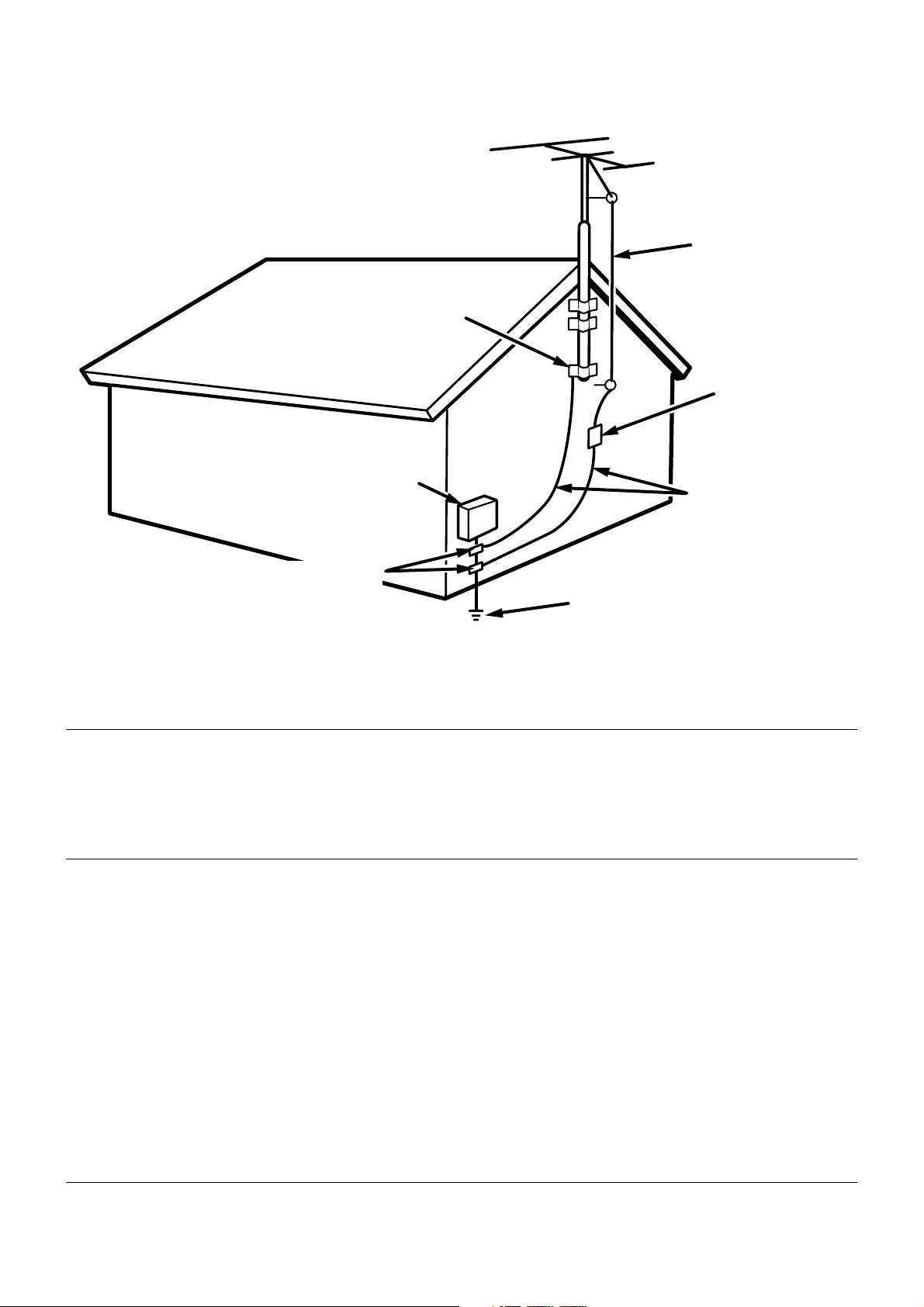
FIGURE 1
EXAMPLE OF ANTENNA GROUNDING AS PER
NATIONAL ELECTRICAL CODE, ANSI/NFPA 70
GROUND
CLAMP
ANTENNA
LEAD IN
WIRE
ANTENNA
DISCHARGE UNIT
(NEC SECTION 810-20)
ELECTRIC
SERVICE
EQUIPMENT
GROUND CLAMPS
POWER SERVICE GROUNDING
ELECTRODE SYSTEM
(NEC ART 250, PART H)
NEC - NATIONAL ELECTRICAL CODE
GROUNDING CONDUCTORS
(NEC SECTION 810-21)
NOTE TO CATV SYSTEM INSTALLER:
This reminder is provided to call the CATV (Cable-TV) system installer's attention to Article 820-40 of the NEC,
which provides guidelines for proper grounding and, in particular, specifies that the cable ground shall be
connected to the grounding system of the building, as close to the point of cable entry as practical.
NOTE:
This equipment has been tested and found to comply
with the limits for a Class B digital device, pursuant to
Part 15 of the FCC Rules. These limits are designed to
provide reasonable protection against harmful interference in a residential installation. This equipment generates, uses and can radiate radio frequency energy
and, if not installed and used in accordance with the
instructions, may cause harmful interference to radio
communications. However, there is no guarantee that
interference will not occur in a particular installation. If
this equipment does cause harmful interference to
radio or television reception, which can be determined
by turning the equipment off and on, the user is encour-
aged to try to correct the interference by one or more of
the following measures:
– Reorient or relocate the receiving antenna.
– Increase the separation between the equipment and
receiver.
– Connect the equipment into an outlet on a circuit
different from that to which the receiver is connected.
– Consult the dealer or an experienced radio/TV tech-
nician for help.
NOTE:Changes or modifications may cause this unit
to fail to comply with Part 15 of the FCC Rules and may
void the user's authority to operate the equipment.
This Class B digital apparatus complies
with Canadian ICES-003.
Cet appareil numérique de la Classe B est
conforme á la norme NMB-003 du Canada.
Page 5
FOREWORD
This section must be read before any connection is made to the
mains supply.
Warnings
Do not expose the equipment to rain or moisture.
Do not remove the cover from the equipment.
Do not insert anything into the equipment through the
ventilation holes.
Do not handle the mains lead with wet hands.
Do not cover the ventilation with any items such as tablecloths,
newspapers,curtains,etc.
No naked flame sources,such as lighted candles,should be
placed on the equipment.
When disposing of used batteries, please comply with
governmental regulations or environmental public instruction’s
rules that apply in your country or area.
INSTALLATION
Remember the following important points when installing the player:
• Do not expose the player to rain or moisture, as this may cause
damage to the player.
• All players produce some heat during operation and this heat must
be allowed to disperes freely. Do not close any ventilation openings
and insure that there is adequate ventilation space behind, beside
and above the player.
• Prevent extra heat from reaching the unit. Never put the player in the
full glare of the sun or near a heat source.
ENGLISH
PRECAUTIONS
The following precautions should be taken when operating the equipment.
GENERAL PRECAUTIONS
CE marking (only EU version)
This product is in conformity with the EMC directive
and low-voltage directive.
EQUIPMENT MAINS WORKING SETTING
Your Marantz product has been prepared to comply with the
household power and safety requirements that exist in your area.
PMD325 product can be powered by 120 V AC only.
COPYRIGHT
Recording and playback of any material may require consent. For
further information refer to the following:
— Copyright Act 1956
— Dramatic and Musical Performers Act 1958
— Performers Protection Acts 1963 and 1972
— any subsequent statutory enactments and orders
When installing the equipment ensure that:
– the ventilation holes are not covered.
– air is allowed to circulate freely around the equipment.
– it is placed on a vibration-free surface.
– it will not be exposed to excessive heat, cold, moisture or dust.
– it will not be exposed to direct sunlight.
– it will not be exposed to electrostatic discharges.
In addition, never place heavy objects on the equipment.
If a foreign object or water does enter the equipment, contact your
nearest dealer or service center.
Do not pull out the plug by pulling on the mains lead; grasp the plug.
It is advisable when leaving the house for an extended period, or
during a thunderstorm, to disconnect the equipment from the mains
supply.
PRECAUTIONS IN CONNECTION
• Be sure to unplug the power cable from the AC outlet or turn off
the POWER switch before proceeding with any connection.
• Connect one cable at a time observing the “input” and “output”.
This will avoid any cross connection between channels and signal
inputs and outputs.
• Insert the plugs securely. Incomplete connection may result in
noise.
• Prior to connecting other audio and video equipment to the
PMD325, please read their owner’s manuals.
1
Page 6

CONTENTS
1. BEFORE USING.................................................................................................... 3
2. ACCESSORIES ..................................................................................................... 5
3. FEATURES ............................................................................................................ 6
ENGLISH
4. CONNECTIONS ....................................................................................................7
5. NAMES AND FUNCTIONS .................................................................................... 9
Front panel ........................................................................................................................................................ 9
Display ............................................................................................................................................................ 10
Remote control unit ......................................................................................................................................... 11
Rear panel ...................................................................................................................................................... 12
6. BASIC OPERATIONS.......................................................................................... 14
Playing CDs .................................................................................................................................................... 14
Playing a specific track ................................................................................................................................... 15
Playing a specific part of a specific track ........................................................................................................ 16
7. ADVANCED OPERATIONS................................................................................. 17
Repeat play (playing the same tracks repeatedly) .......................................................................................... 17
Random play (Playing tracks in a random sequence) .................................................................................... 18
AMS play (Searching for a specific track) .......................................................................................................18
Program play (playing tracks in the preferred sequence) ............................................................................... 19
Delete program play (play with undesired tracks skipped) ............................................................................. 21
Pitch control (changing the play speed) .......................................................................................................... 24
Setting the position to start listening to play (manual cue) ............................................................................. 25
8. SETTING THE PLAY FUNCTIONS ..................................................................... 26
Using EASY JOG ............................................................................................................................................ 26
Various play functions (play modes) ............................................................................................................... 28
9. OTHER FUNCTIONS ..........................................................................................38
Last memory ................................................................................................................................................... 38
CD-TEXT ........................................................................................................................................................ 38
CD-R/RW disc play ......................................................................................................................................... 39
MP3 ................................................................................................................................................................ 39
Fader start ...................................................................................................................................................... 42
How to use the RS-232C connector ............................................................................................................... 43
Installing the rack-mounting kit ....................................................................................................................... 44
10. SPECIFICATIONS AND DIMENSIONS ...............................................................45
11. TROUBLESHOOTING ......................................................................................... 46
2
Page 7
1. BEFORE USING
PLAY/PAUSE
+
OPEN/CLOSE
CUESTOP
EASY JOG
-
PHONESLEVELQUICK REPLAY
POWER ON/OFF
CD PLAYER PMD325
1
23456789
0
TIMER
DISC
TEXT
123456 7891011121314151617181920
TTL
TRK INDX
TTL
TIME
MP3
RNDM
PROG A — B
RPT1S.PLAY
END
WARNING
ALBUM
— +
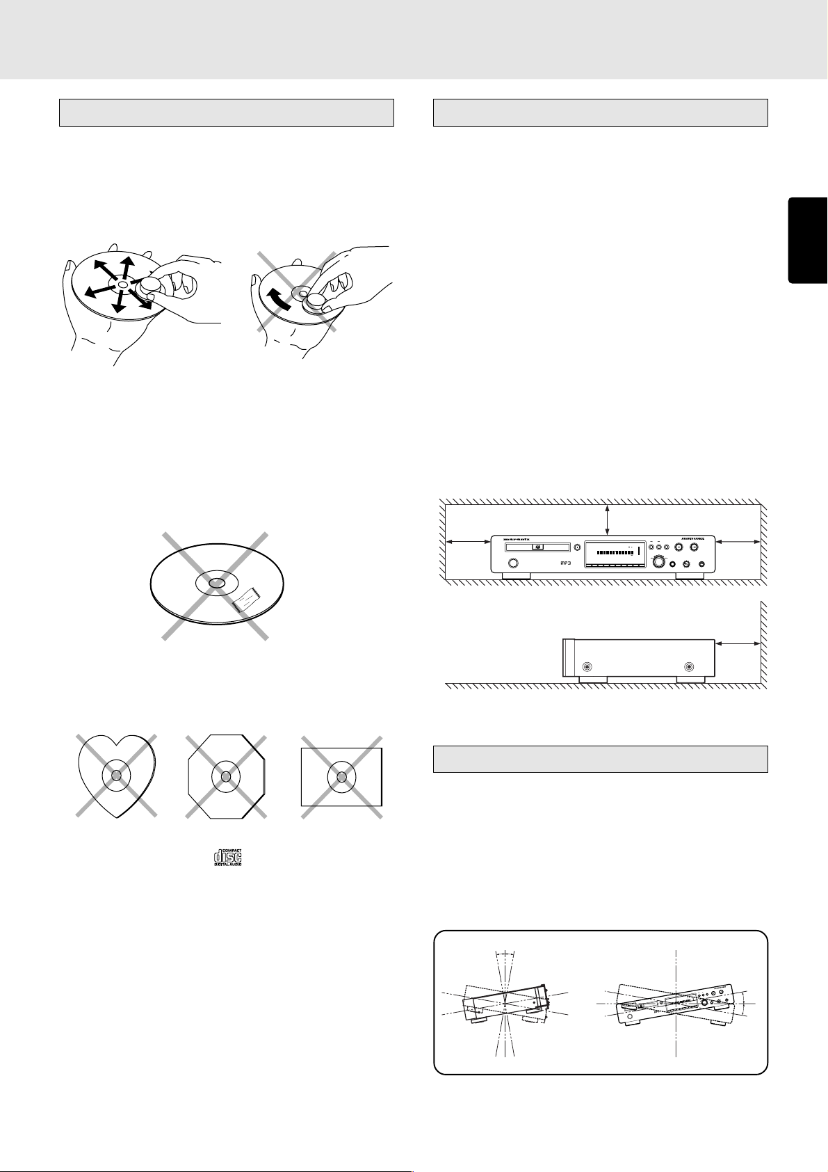
Notes about the discs
* Handle the discs carefully so as not to scratch their
surfaces.
* Keep the surfaces of the discs clean at all times.
When cleaning the surfaces of discs, always be sure to
use the special cleaner and wipe the surfaces in the
directions shown in the figure below.
• Wipe the surface radially
from the center.
* Do not attach pieces of paper or stickers to the label
surfaces of the discs.
When a disc has a piece of plastic tape or rental CD label
with paste protruding from the edge or when a disc still
bears traces of sticky tape or adhesive labels, do not
attempt to play it. If such a disc is played on the CD player,
you may find that you cannot remove it or that some other
kind of malfunctioning may occur.
• Do not wipe the surface in
the circumferential direction.
Inappropriate places for installation
To keep your player in perfect working order for the longest
possible time, avoid installing the player in the following
locations.
• Wherever it will be exposed to direct sunlight
• Wherever it will be close to a heater or other heat-radiating
appliance
• Wherever the humidity is high or ventilation is poor
• Wherever it is very dusty
• Wherever it will be subject to vibration
• On top of a rickety stand or in an unstable location which
is tilted at an angle
• On top of an amplifier or other component which dissipates
a great deal of heat
• In an audio rack with little space at the top and bottom or
other location where the heat dissipation will be obstructed
To ensure proper heat dissipation, install the player while
leaving clearances between the player and wall or other
components, as shown in the figure below.
10 cm or more
2 cm or more
10 cm or more
ENGLISH
* Do not use discs which come in special shapes.
Do not attempt to play heart-shaped or octagonal discs or
discs with any other special shapes. You may find that
you cannot remove them or that some other kind of
malfunctioning may occur in the player.
* Use discs which satisfy the CD standards such as those
with the “CD logo” or “
” mark on their disc label
surfaces.
No guarantees are made for playback if discs which do
not satisfy the appropriate CD standards are used.
Similarly, no guarantees are made for their sound quality
even if it is possible to play such discs.
* To protect your discs from damage, avoid placing them
in the following locations.
• Where they will be exposed to direct sunlight or where
they will be close to a heater or other heat-radiating
appliance
• Where the humidity level is high or it is very dusty
• Near a window or other such location where they may be
exposed to rain
* Get into the habit of putting the discs back in their cases
after use.
5 cm or more
Installation precautions
In order to ensure that the unit will operate correctly, install
and operate it within +/-10 degrees from the horizontal plane.
If the unit tilts too far in one direction, its disc may be pinched
or it may not be possible to open and close the disc holder
properly.
When the unit is to be installed in a 19-inch rack for use, secure
it firmly in four places.
Refer to page 45 for the outline drawing.
10°10°
E
S
U
A
P
/
Y
A
L
P
E
U
C
P
O
T
S
+
S
M
E
U
N
B
O
L
H
A
P
—
G
O
J
Y
.PLAY
S
S
A
L
E
E
E
V
1
E
TIM
L
T
P
R
L
T
T
B
—
A
G
O
E
R
P
S
O
M
L
D
C
N
/
R
N
E
P
O
3
INDX
MP
R
IME
T
TRK
L
T
5
T
32
DISC
MD
P
ER
Y
A
L
D P
C
F
F
/O
N
O
R
E
W
O
P
1920
18
1617
15
D
14
N
E
13
12
11
G
10
IN
9
N
R
8
A
7
W
6
5
4
3
2
1
0
T
X
E
T
89
7
6
45
3
2
1
10°
Y
A
L
P
E
R
K
IC
U
Q
+
-
10°
3
Page 8

BEFORE USING
Do not place objects on top
• Refrain from placing any objects on top of the player.
Cautions on handling power cord
ENGLISH
• Do not touch the power cord with wet hands.
• When disconnecting the power cord, always make sure
that you take hold of the plug. Yanking out or bending the
cord can damage it and/or cause electric shocks or a fire.
• Get into the habit of disconnecting the power plug before
leaving home.
Do not attempt repairs yourself
• Refrain from lubricating the player: doing so can cause
malfunctioning.
• Only qualified engineers with specialized expertise are
authorized to repair the pick-up and parts inside the player.
Precautions
Cautions on handling batteries
Misuse of the batteries can result in electrolyte leakage,
rupturing, corrosion, etc.
Bear in mind the following points when using batteries.
• Remove the batteries from the remote control unit if the
unit is not going to be used for a prolonged period (a month
or more).
• Do not use an old battery together with a new one.
• Insert the batteries while ensuring that their
are properly aligned with the corresponding markings on
the remote control unit.
• Batteries with the same shape may have different voltages.
Do not use different types of batteries together.
• If electrolyte has leaked, thoroughly wipe the inside of the
battery compartment, and then insert new batteries.
and poles
• In winter, droplets of water form on the insides of the
windows of a heated room: this is called condensation.
This CD player uses an optical lens, so the condensation
may form in the following cases.
- In a room immediately after the heating has been turned
on
- In a room where the humidity level is high
- When the player has been suddenly brought from a cold
location into a warm room
Since, in cases like this, the track numbers may not be
read and the player is prevented from operating properly,
wait about 30 minutes, and then operate the player.
• This player may cause interference on a tuner or TV set. If
this is the case, place it further away from the tuner or TV
set.
• Compact discs have much less noise than analog records
and hardly any noise is heard before play starts. Bear in
mind, therefore, that if the volume control on the amplifier
is set too high, you will risk damaging other audio
components.
• This player is designed to play music CDs only. It cannot
play CD-ROMs used with personal computers, game CDs,
video CDs or DVDs (video/audio).
4
Page 9
2. ACCESSORIES
Checking the accessories
After opening the cover of the packing box, check that the
following accessories are included.
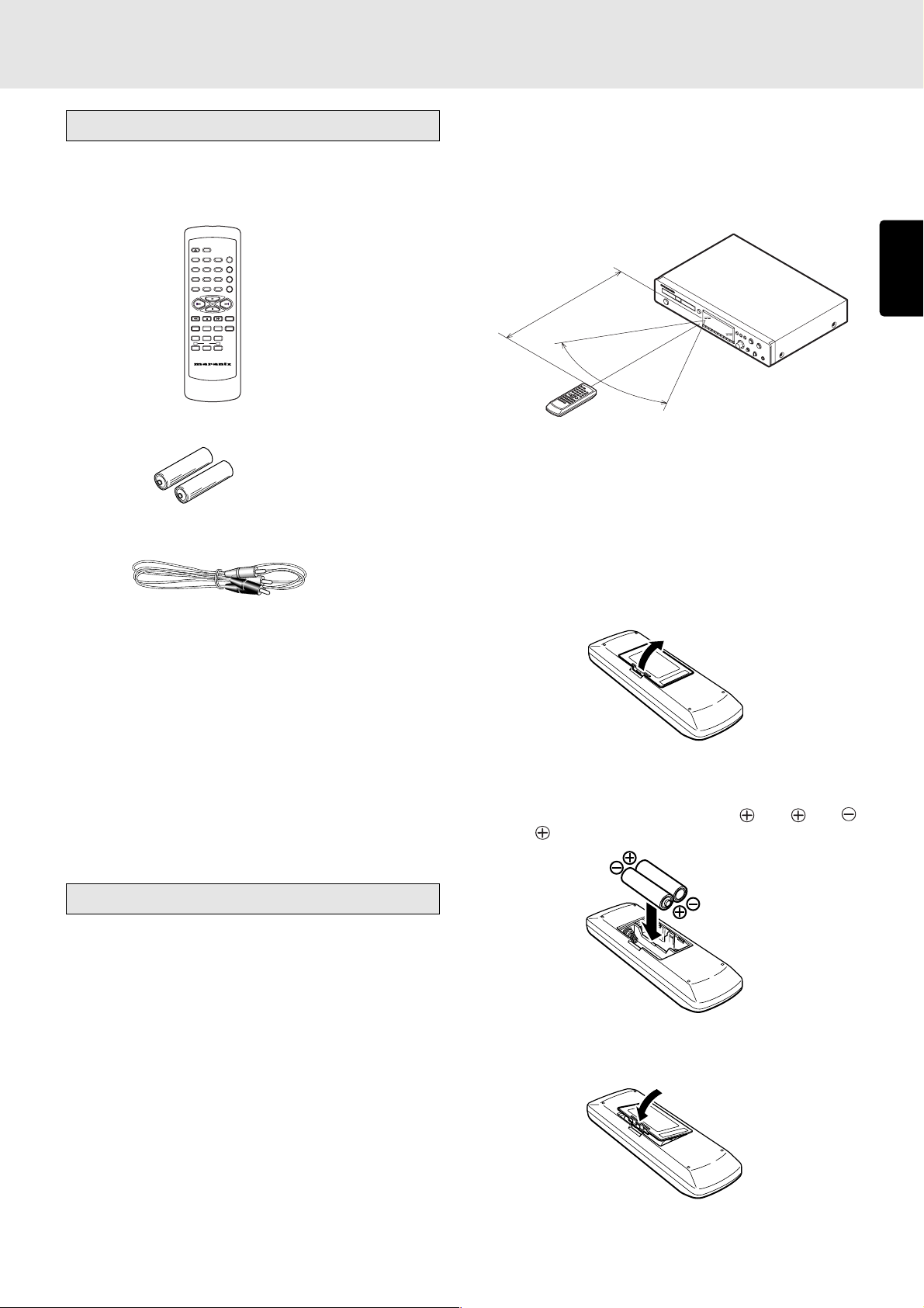
• Remote control unit (RC7300CD)
OPEN/CLOSE
DISPLAY
REPEAT
3
12
AMS
654
RANDOM
978
PROGRAM0A-B
CANCEL
TIME
SCROLL/
TEXT
MENU ENTER
RECALL
Q. REPLAY
INDEX -
INDEX +
PITCH
-
+
RESET
REMOTE CONTROLLER
RC7300CD
• Size “AA” batteries x 2
• Audio connecting cord (1 meter long)
• Operational range
As shown in the figure below, the player can be operated
by the remote control unit in a range which of about 5 meters
from the player’s remote sensor and over an angle up to
30 degrees to the left and 30 degrees to the right of the
position directly in front.
5m
60°
• Loading batteries
Before using the supplied remote control unit for the first
time, load the batteries in the remote control unit. The
batteries provided are used to verify the operations of the
remote control unit only.
ENGLISH
• User Guide
• Warranty card
Usage of REMOTE CONTROL UNIT
• Precautions
- Do not allow direct sunlight, an inverter fluorescent light
or other strong source of light to shine onto the player’s
infrared signal reception window (remote sensor).
Otherwise, the operation of the remote control unit may
be disabled.
- Bear in mind that operating the remote control unit may
cause other devices operated by infrared rays to be
operated by mistake.
- The remote control unit cannot be operated if the space
between the controller and the player’s remote sensor is
obstructed.
- Do not place any objects on top of the remote control
unit. Doing so may cause one or more buttons to be
held down which will cause the batteries to run down.
1 Take hold of the tab on the battery cover which is found
on the back side of the remote control unit, and pull it up.
2 Load the two new size “AA” batteries inside the battery
compartment while taking care to align their polarities
correctly with the polarity markings (
with and
with ).
Size “AA” (SUM-3) batteries x 2
3 Push the battery cover down in the direction of the arrow
to close it.
5
Page 10

3. FEATURES
• Play of unfinalized CD-R and CD-RW discs
supported
The PMD325 can play even partially once-written CD-R
and CD-RW discs that could not be played by conventional
CD players. Since unfinalized discs which have some
ENGLISH
recording time left can be played, even partially edited
discs can be played.
• MP3 play and ID3 tag display supported
The PMD325 supports not only the play of CD-R and CDRW discs recorded with MP3 files but also the ID3 tags
which are the text information of MP3 files so that text giving
the track information or artists’ names can be displayed.
(Japanese characters cannot be displayed.)
• CD-TEXT displays supported
• Pitch control function
The PMD325 comes with a pitch control function that
enables the play speed (pitch) to be varied in a -12% to
+12% range. This is useful when practicing to play a
musical instrument.
• Quick replay function
By means of a single-touch action, the quick replay function
returns play to a position, which is a number of seconds
(setting range: 1 to 30 seconds) that has been set, before
the position of the track now playing. This enables you to
return and listen again to the section a little before the
position where the track is now playing.
• End monitor function
By means of a single-touch action, the end monitor function
plays the end part of the track now playing for the duration
(setting range: 1 to 30 seconds) which has been set. This
makes it easy to check the end part of the track which is
now being played.
• Manual cue function
By setting the play start position in advance, play can
always be started at the preset position.
• End warning function
When the end of the track being played is approached,
the end warning indicator starts flashing to signal that the
end of the track now playing is near.
• Wide range of play modes
Among the many play modes featured by the PMD325 are
single play (STOP, NEXT, RECUE), programmed play,
repeat play (ALL, 1-track, A-B) and auto pause.
• External control interfaces
The PMD325 features RS-232C, parallel control I/O and
remote I/O as external control interfaces.
• Timer play supported
• CS4396 high-performance D/A converter (made
by Cirrus Logic)
High-linearity play is achieved by oversampling the PCM
signals to 128fs inside the D/A converter and combining
dynamic element matching (DEM) with multi-element
switched capacitors.
• Digital and analog areas configured separately
The digital area consisting of the servo, decoder and
microcomputer circuitry is mounted en bloc on the CD
mechanism PCB away from the analog (audio circuitry)
area.
This keeps out the pulsive noise generated from the digital
area and yield a pure sound reproduction.
• Auto cue function
This enables play to start automatically from the position
where the sound begins.
6
Page 11
4. CONNECTIONS
A
E
This CD player is connected to an amplifier, CD recorder and
other components for use. To ensure that the components
are connected properly, refer to the instruction manuals that
come with the components to be connected.
Before connecting the components, be absolutely sure to turn
off their power.
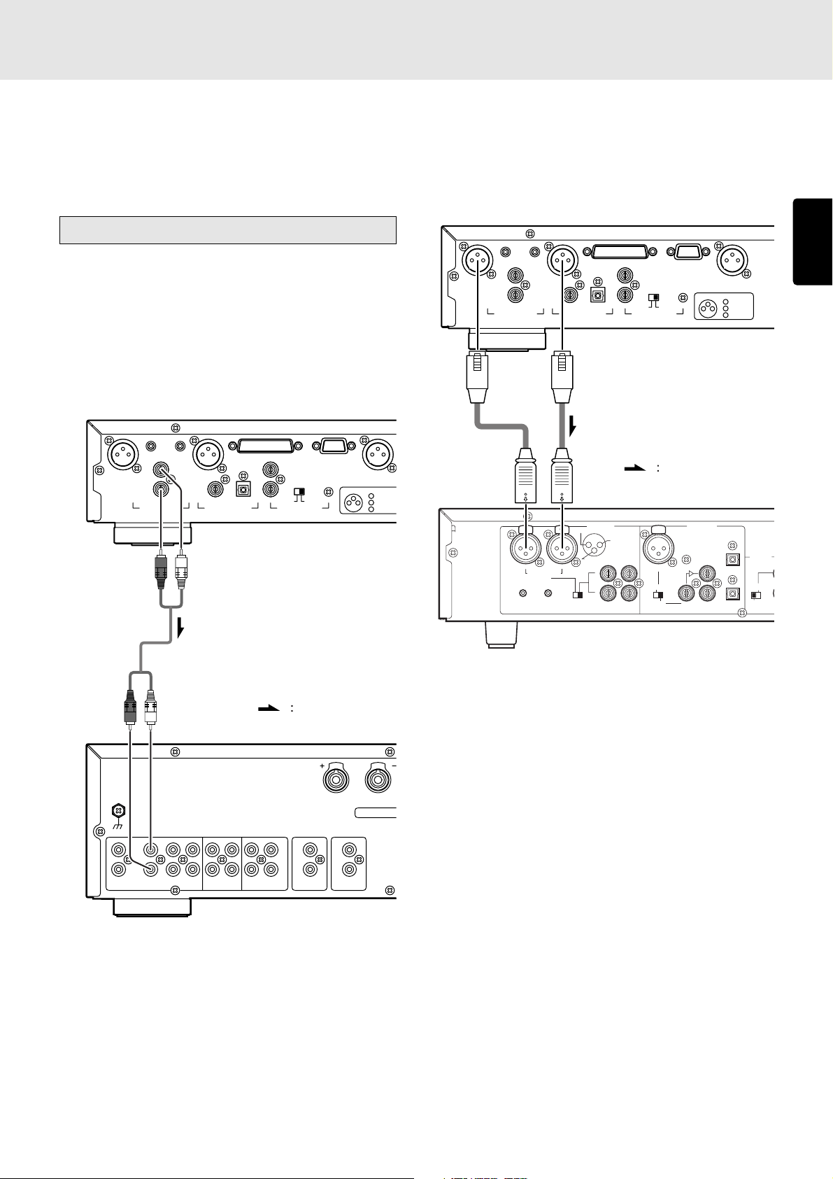
Connecting to an amplifier
• Connecting the analog unbalanced
output connectors
Use the audio connecting cord to connect the player with a
stereo amplifier or AV amplifier. Do not connect the player to
the PHONO input connectors on the amplifier.
When making the connections, insert the plugs securely into
the connectors. Failure to insert the plugs securely may result
in noise.
BALANCED
R L
ANALOG OUT
(Red)
OUTPUT LEVEL
L
R
DIGITAL OUT
(White)
EXTERNAL INTERNAL
OPT.COAX.
IN
OUT
REMOTE CONTROL
RS232CCONTROL I/O
DIGITAL OUT
(
SPDIF
CONNECTION
1 GND
2 HOT
231
3 COLD
• Connecting the ANALOG BALANCED
OUT (analog balanced output) connectors
Connect the unit to the stereo amplifier or AV amplifier using
XLR connector cables.
When making the connections, insert the plugs firmly into the
connectors. Failure to insert them securely gives rise to noise.
BALANCED
R L
OUTPUT LEVEL
L
ANALOG OUT
R
DIGITAL OUT
OPT.COAX.
EXTERNAL INTERNAL
REMOTE CONTROL
XLR connector cable
(available on the market)
)
(+)
(-)
PUSH
NEUTRIK
R
BALANCED
IN
R
-TRIM-
0 +22
0+22
(REF=+16dBu/0dBFS)
L
ANALOG
PUSH
HOT(+)
INPUT
2
COLD(-)
1
3
L
R
GROUND
ININOUT
NEUTRIK
L
SELECT
IN
OUT
Signal flow
PUSH
NEUTRIK
AES/EBU
SPDIF
RS232CCONTROL I/O
DIGITAL OUT
(
)
SPDIF
CONNECTION
1 GND
(+)
2 HOT
IN
(SPDIF)
231
DIGITAL
LOOP
OUT
OUT
3 COLD
OUT
(-)
REMOTE
(RC5)
EXT.
INT.(IR)
IN
ENGLISH
(Red)
PHONO
Audio connecting cord (supplied)
(White)
GND
L
R
CD
AUX
TUNERPHONO
REC
PLAY
/DVD
CD-R
Amplifier
Amplifier, CD recorder, etc.
Signal flow
R
SPE
SPEAKERS IMP
L
L
R
REC
PLAY
MD/TAPE
IN
R
OUT
REMOTE PRE OUT
CONTROL
7
Page 12
R
CONNECTIONS
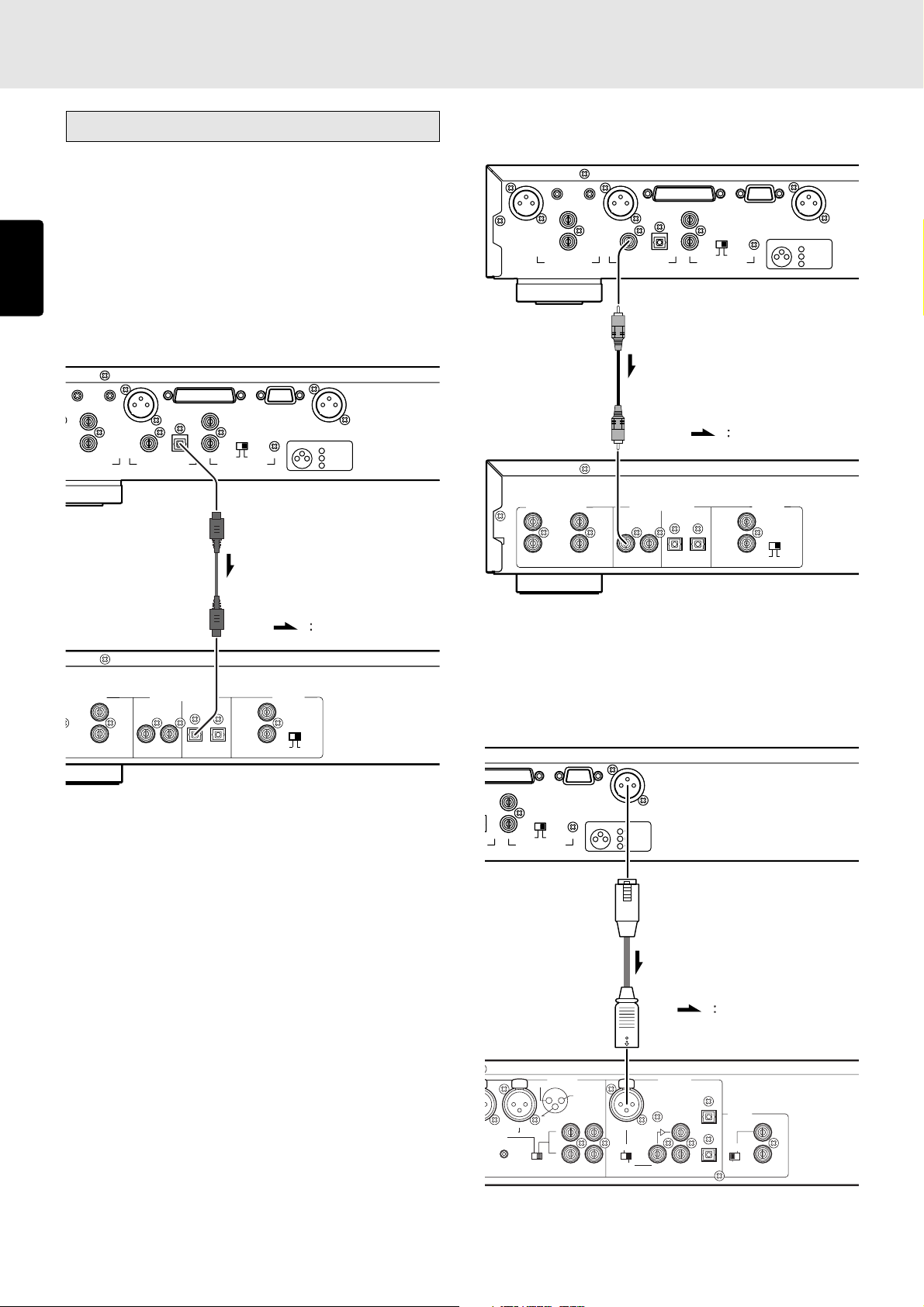
Connecting to a digital audio component
This unit comes with three different digital output connectors:
OPTICAL (x1), COAXIAL (x1) and DIGITAL OUT (SPDIF)
(digital balanced).
You can enjoy digital recording when the player is connected
ENGLISH
to a CD recorder or other digital recording component.
• Connecting the optical output connector
Use an optical digital connecting cable available on the
market. Insert the plug firmly in until it clicks into place. Do
not bend or bundle the optical digital connecting cable.
BALANCED
OUTPUT LEVEL
ANALOG OUT
L
L
R
DIGITAL OUT
OPT.COAX.
EXTERNAL INTERNAL
REMOTE CONTROL
RS232CCONTROL I/O
IN
OUT
DIGITAL OUT
CONNECTION
231
(
SPDIF
1 GND
2 HOT
3 COLD
• Connecting the coaxial output connector
Use a coaxial digital connecting cable available on the market.
BALANCED
R L
OUTPUT LEVEL
L
ANALOG OUT
R
DIGITAL OUT
EXTERNAL INTERNAL
OPT.COAX.
REMOTE CONTROL
Coaxial digital connecting cable
(available on market)
)
(+)
(-)
INPUT
ANALOG IN/OUT
L
R
OUTPUT
INPUT
DIGITAL IN/OUT
OUTPUT
OPTICAL COAXIAL
INPUT OUTPUT
OUT
IN
RS232CCONTROL I/O
DIGITAL OUT
CONNECTION
231
Signal flow
REMOTE
CONTROL
IN
OUT
INTERNAL
EXTERNAL
(
SPDIF
1 GND
2 HOT
3 COLD
)
(+)
(-)
Optical digital connecting cable
(available on market)
CD recorder, MD deck, AV amplifier, etc.
Signal flow
• DIGITAL OUTPUT (SPDIF)
LOG IN/OUT
L
R
OUTPUT
INPUT
DIGITAL IN/OUT
OUTPUT
OPTICAL COAXIAL
INPUT OUTPUT
REMOTE
CONTROL
IN
OUT
EXTERNAL
INTERNAL
CD recorder, MD deck, AV amplifier, etc.
(digital balanced output) connector
Use an XLR connector cable available on the market to
connect this connector.
NTROL I/O
EXTERNAL INTERNAL
REMOTE CONTROL
RS232C
IN
OUT
DIGITAL OUT
CONNECTION
231
(
SPDIF
1 GND
2 HOT
3 COLD
)
(+)
(-)
XLR connector cable
(available on the market)
Signal flow
BALANCED
IN
RIM-
0
2
Bu/0dBFS)
ANALOG
PUSH
HOT(+)
INPUT
2
COLD(-)
1
3
L
R
GROUND
ININOUT
AES/EBU
NEUTRIK
L
L
+22
SELECT
PUSH
NEUTRIK
SPDIF
IN
(SPDIF)
DIGITAL
LOOP
OUT
OUT
REMOTE
(RC5)
OUT
IN
EXT.
INT.(IR)
IN
OUT
CD recorder, MD deck, AV amplifier, etc.
8
Page 13
5. NAMES AND FUNCTIONS
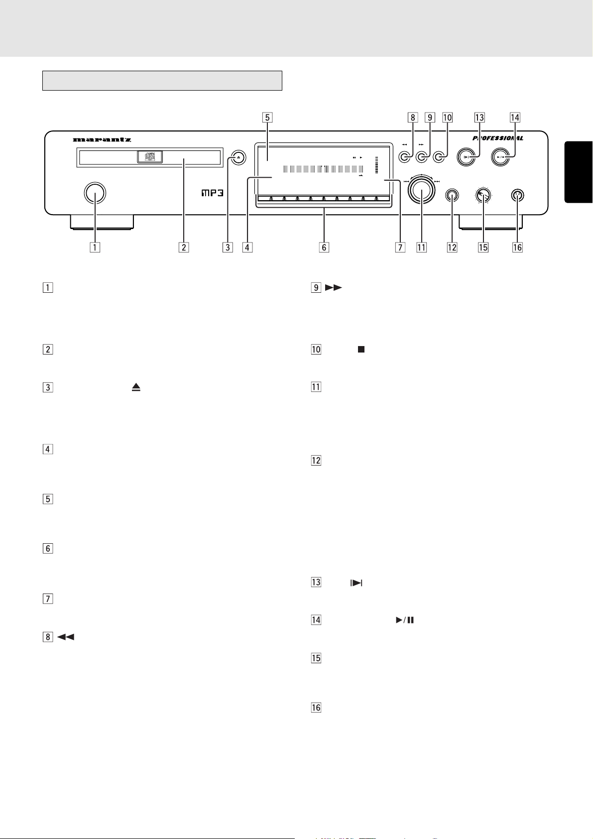
Front panel
CD PLAYER PMD325
POWER ON/OFF
OPEN/CLOSE
END
WARNING
1
POWER ON/OFF switch
This is used to turn the player’s power ON and OFF. When
it is pressed, the display lights and the power is turned
on; when it is pressed again, the power is turned off.
Disc tray
This is where the CD to be played is placed.
OPEN/CLOSE button
This is used to open and close the disc tray. When it is
pressed, the disc tray opens; when it is pressed again, it
closes.
Remote sensor
This senses the infrared control signals sent from the
remote control unit.
END WARNING indicator
This starts flashing 15 seconds before the end of the track
now playing is reached.
Numeric buttons (0 to 9)
These are used to specify the numbers of the tracks to be
played.
Display
This shows the settings, play status, text information, etc.
(search backward) button
This is used to search backward during play.
It also serves as the album selector button when playing
discs with MP3 files recorded on them.
TIMER
RNDM
PROG A — B
TRK INDX
RPT1S.PLAY
TTL
TIME
MP3
DISC
TTL
TEXT
12 34 56 7891011121314151617181920
23456789
(search forward) button
This is used to search forward during play.
It also serves as the album selector button when playing
discs with MP3 files recorded on them.
STOP button
This is used to stop play.
EASY JOG/push enter button
Preceding or subsequent tracks can be searched (tracks
can be skipped) by turning the jog dial clockwise or
counterclockwise. In addition, the play functions (play
modes) can be set using the jog dial.
QUICK REPLAY button
This is used to search backward from the current play
position for the time equivalent to the setting and resume
play.
The button is operated by the play setting function as the
end monitor. In the case of the end monitor, play is
resumed from the position which is before the end position
of the track now playing by the duration which has been
set.
CUE button
This button is used to move to and start set cue points.
PLAY/PAUSE button
This is used to start play or temporarily suspend play.
PHONES LEVEL control
This is used to adjust the headphones volume level. The
level increases when it is turned clockwise.
0
—+
ALBUM
EASY JOG
PLAY/PAUSE
CUESTOP
PHONESLEVELQUICK REPLAY
ENGLISH
+
-
PHONES jack
The headphones are connected to this jack. Use
headphones that come with a standard plug.
9
Page 14
NAMES AND FUNCTIONS
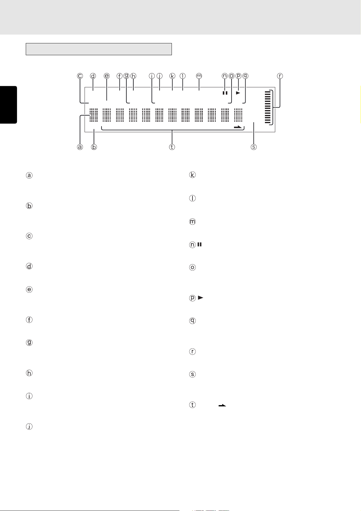
Display
ENGLISH
TIMER
DISC
TEXT
RNDM
PROG A — B
TTL
12 34 56 78 910 1112 1314 1516 1718 1920
TRK INDX
Main display
This displays the time information and text information of
the disc played, the setting menus, etc.
TEXT indicator
This lights when a disc supporting CD-TEXT has been
loaded.
DISC indicator
This flashes during readout of the table of contents (TOC)
information on the disc.
RPT
1
S.PLAY
TTL
TIME
MP3
RPT (repeat) indicator
This lights during repeat play.
1 (1-track repeat) indicator
This lights during 1-track repeat play.
S.PLAY (single track play) indicator
This lights during single track play.
(pause) indicator
This lights when play is temporarily suspended.
TIMER indicator
This lights when timer play has been set.
TTL (total track) indicator
This lights above the display of the total number of tracks
recorded on the disc.
RNDM (random) indicator
This lights during random play.
TRK (track) indicator
This lights above the display of the number of the track
being played, etc.
PROG (program) indicator
This lights during program play.
INDX (index) indicator
This lights above the display of the index number being
played, etc.
A-B (A-B repeat) indicator
This lights during A-B repeat play.
TTL (total time) indicator
When the total remaining time or total program time is
displayed, this lights above that display.
(play) indicator
This lights during play.
TIME indicator
This lights while the elapsed time or other such time is
displayed.
Pitch control indicator
This displays the pitch control setting.
MP3 indicator
This lights when a disc on which MP3 files have been
recorded is loaded.
1 - 20, (music calendar)
This displays the track numbers recorded on the disc, the
track numbers still to be played, and the track numbers
programmed for program play. During MP3 file play, the
album is displayed.
10
Page 15
NAMES AND FUNCTIONS
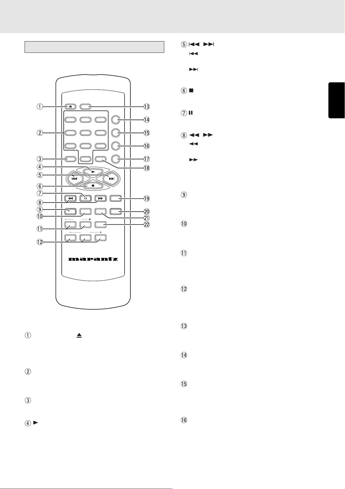
Remote control unit
OPEN/
CLOSE
DISPLAY
12
PROGRAM
TEXT
MENU ENTER
INDEX
PITCH
RESET
3
654
978
CANCEL
0
Q. REPLAY
REPEAT
AMS
RANDOM
A-B
TIME
SCROLL/
RECALL
, (track skip) buttons
: Use this to return to the start of the track now playing
or return to the start of the previous track.
: Use this to advance to the start of the subsequent
track.
(stop) button
This is used to stop the play.
(pause) button
This is used to temporarily suspend play.
, (search) buttons
: This button is used to search backward when it is
held down during play.
: This button is used to search forward when it is held
down during play.
These buttons also serve as the album selector buttons
when playing discs with MP3 files recorded on them.
TEXT button
This is used to switch the main display from the time display
to the text display.
MENU button
This is used to switch to the play function (play mode)
setting menu.
ENGLISH
REMOTE CONTROLLER
RC7300CD
OPEN/CLOSE button
This is used to open and close the disc tray.
When it is pressed, the disc tray opens; when it is pressed
again, it closes.
Numeric buttons (0 to 9)
These are used to specify the numbers of the tracks to be
played.
PROGRAM button
This is pressed to initiate program play.
(play) button
This is used to start play.
INDEX -/+ (index down/up) buttons
These are used to skip and search indexes. They can be
used with discs on which index numbers have been
recorded.
PITCH -/RESET/+ (pitch control down/reset/
up) buttons
These are used to adjust the play speed (pitch) with a
± 12% range.
DISPLAY button
This button is used to select the brightness of the display
window.
REPEAT button
This is used to play one track or all the tracks on the disc
repeatedly.
AMS (auto music scan) button
This is used to play the intros of all the tracks in sequence
starting from the first track for the duration equivalent to
the setting.
RANDOM button
This is used to play the tracks in a random sequence.
11
Page 16
NAMES AND FUNCTIONS
ENGLISH
A-B (A-B repeat) button
This is used to set start point (A) and end point (B) when a
particular section is to be played repeatedly.
CANCEL button
This is used to cancel the programmed tracks.
TIME button
This switches the main display from the text display to the
time display. It can also switch the time display during
play.
It can display how much time has elapsed and how much
play time remains for the current track as well as how much
time has elapsed and how much play time remains for the
whole disc.
During MP3 file play, it displays the elapsed time only.
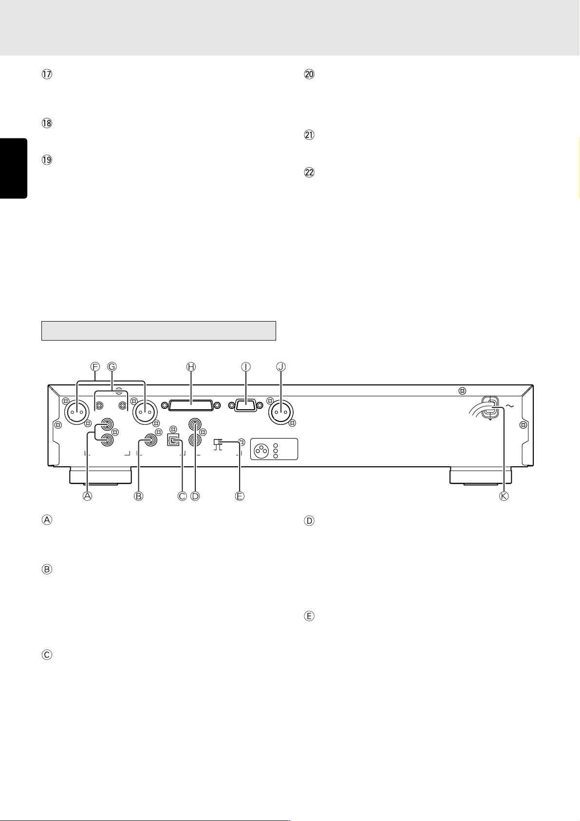
Rear panel
SCROLL/RECALL button
This is used to scroll the text display when text is displayed.
When it is pressed during program play, it is possible to
check which tracks have been programmed.
ENTER button
This is used to enter the play function settings.
Q.REPLAY (quick replay) button
This is used to search backward from the current play
position for the time equivalent to the setting and resume
play.
Furthermore, operation is performed as the end monitor
using one of the play setting functions. In the case of the
end monitor, play is resumed from the position, which is a
number of seconds that has been set, before the end
position of the track now playing.
BALANCED
R L
OUTPUT LEVEL
L
R
ANALOG OUT
DIGITAL OUT
IN
OUT
OPT.COAX.
EXTERNAL INTERNAL
REMOTE CONTROL
RS232CCONTROL I/O
DIGITAL OUT
CONNECTION
231
ANALOG OUT (analog output) connectors
The music signals during play are output from these
connectors.
DIGITAL OUT COAX. (digital coaxial output)
connector
The music signals during play are output digitally from
this coaxial output connector.
* Digital signals are not output during MP3 file play or pitch
control play.
DIGITAL OUT OPT. (digital optical output)
connector
The music signals during play are output digitally from
this optical output connector.
* Digital signals are not output during MP3 file play or pitch
control play.
(
SPDIF
1 GND
2 HOT
3 COLD
)
(+)
(-)
REMOTE CONTROL IN and OUT connectors
Using the remote control connecting cable, these
connectors enable this player to be connected to a
Marantz component equipped with remote control
connectors. These connections make it possible to control
an entire system that centers on the amplifier or other such
component.
EXTERNAL/INTERNAL switch
Before the player was shipped from the factory, this switch
was set to INTERNAL to enable the remote sensor built
into the player to be used.
Before using the connecting cable to make the connection
between the player and the remote control connectors on
a Marantz equipment, set the switch to EXTERNAL.
Note:
* Signals cannot be received from the remote control
unit if the switch is kept at EXTERNAL when the player
is to be used on its own.
12
Page 17

NAMES AND FUNCTIONS
ANALOG BALANCED OUT (analog balanced
output) connector
The signals of the music now playing are output from this
connector.
Using an XLR connector cable, connect the connector to
a component equipped with an analog balanced input
connector.
Note:
* Before connecting the unit to another component,
check that the XLR connectors have the same pin
layout.
If they have a different layout, reconnect the
conductors of the XLR connector cable in such a way
that the pin layouts match.
Pin layout of the unit’s XLR connector pins
1 GND
(+)
231
2 HOT
3 COLD
(-)
ANALOG BALANCED OUTPUT LEVEL control
This control is used to adjust the output level of the
ANALOG BALANCED OUT (analog balanced output)
connector.
The output level is increased by turning the control
clockwise.
Note:
* Do not apply excessive force to the control when
adjusting it.
* The output level and channel balance were adjusted
before the unit was shipped from the factory. (Output
level: +16 dBu)
CONTROL I/O (control input/output) connector
This connector is used to connect the remote control input/
output signals. For details, refer to “How to use the
CONTROL I/O (control input/output) connector” (page 41).
RS-232C connector
Using serial communication, the control signals from the
external source and the status information from the unit
are output through this connector. For details, refer to
“How to use the RS-232C connector” (page 43).
DIGITAL OUTPUT (SPDIF) (digital balanced
output) connector
The signals of the music now playing are digitally output
through this balanced output connector.
Use an XLR connector cable to connect the connector
with a component equipped with a digital balanced input
connector.
Digital signals are not output while MP3 files are playing
or during pitch control play.
AC POWER SOURCE CONNECTION
With the POWER switch set to the OFF position, plug the
mains lead into a mains outlet providing the right voltage.
ENGLISH
13
Page 18

6. BASIC OPERATIONS
Playing CDs
ENGLISH
POWER ON/OFF
CD PLAYER PMD325
OPEN/CLOSE
END
WARNING
1
TIMER
RNDM
PROG A — B
RPT1S.PLAY
DISC
TTL
TRK INDX
TTL
TEXT
12 3456 78 9101112 1314 151617181920
23456789
TIME
MP3
0
— +
CUESTOP
ALBUM
EASY JOG
2 3, 4 5
OPEN/CLOSE
3, 4
DISPLAY
12
PROGRAM
REPEAT
3
AMS
654
RANDOM
978
A-B
CANCEL
0
5
TIME
MENU ENTER
INDEX +
PITCH
RESET
RC7300CD
Q. REPLAY
+
SCROLL/
RECALL
TEXT
INDEX -
-
REMOTE CONTROLLER
PLAY/PAUSE
PHONESLEVELQUICK REPLAY
+
-
• Stopping play
PLAY/PAUSE
CUESTOP
OG
+
-
PHONESLEVELQUICK REPLAY
Press the button on the player or remote control unit during
play.
• Pausing play
PLAY/PAUSE
CUE
TIME
PHONESLEVELREPLAY
+
-
1. Turn on the power of the amplifier to which the player is
connected, and use the input selector on the amplifier to
select “CD” (the player’s input source which has been
connected).
2. Press the POWER button on the player to turn on the power.
3. Press the OPEN/CLOSE button on the player or remote
control unit. Place the CD to be played in the extended
disc tray while ensuring that the label with the printed text
is facing up.
In the case of a single (8 cm) CD, align it with the
indentation in the center of the tray.
4. Press the OPEN/CLOSE button on the player or remote
control unit to retract the disc tray. Pushing the front of the
disc tray lightly also causes the tray to be retracted. Once
the disc tray has been retracted, “TOC Reading” appears
on the display, after which the total number of CD tracks
and total remaining time are displayed. In the case of a
disc that supports CD-TEXT, the album title is displayed,
and then the total number of CD tracks and total remaining
time are displayed.
During play, press the button on the player or button on
the remote control unit to temporarily suspend play.
To resume play from the place where it was temporarily
suspended, press the
button on the remote control unit.
or
button on the player or the button
• Removing the CD
LAYER PMD325
After play has finished, press the OPEN/CLOSE button on
the player or remote control unit to extend the disc tray, and
remove the CD.
After the CD has been removed, press the OPEN/CLOSE
button again to retract the disc tray. The disc tray should
always be retracted when the player is not in use.
OPEN/CLOSE
OPEN/
CLOSE
DISPLAY
5. Press the button on the player or button on the
remote control unit to start play. Adjust the volume level
at the amplifier.
14
Page 19
BASIC OPERATIONS
Playing a specific track
• Specifying the number of a track to be
played (direct search)
Select the number of the track to be played directly by pressing
the numeric buttons (0 to 9) on the player or remote control
unit.
To select track number 10 or above, use the numeric buttons
to select the higher digit first and then select the lower digit.
Once the number of the track is selected, play will start
automatically.
Example: To play track 3
Press the “3” numeric button.
1
234
Example: To play track 12
Press the “1” numeric button.
1
234
OPEN/
CLOSE
DISPLAY
12
OPEN/
CLOSE
DISPLAY
12
REPEAT
3
REPEAT
3
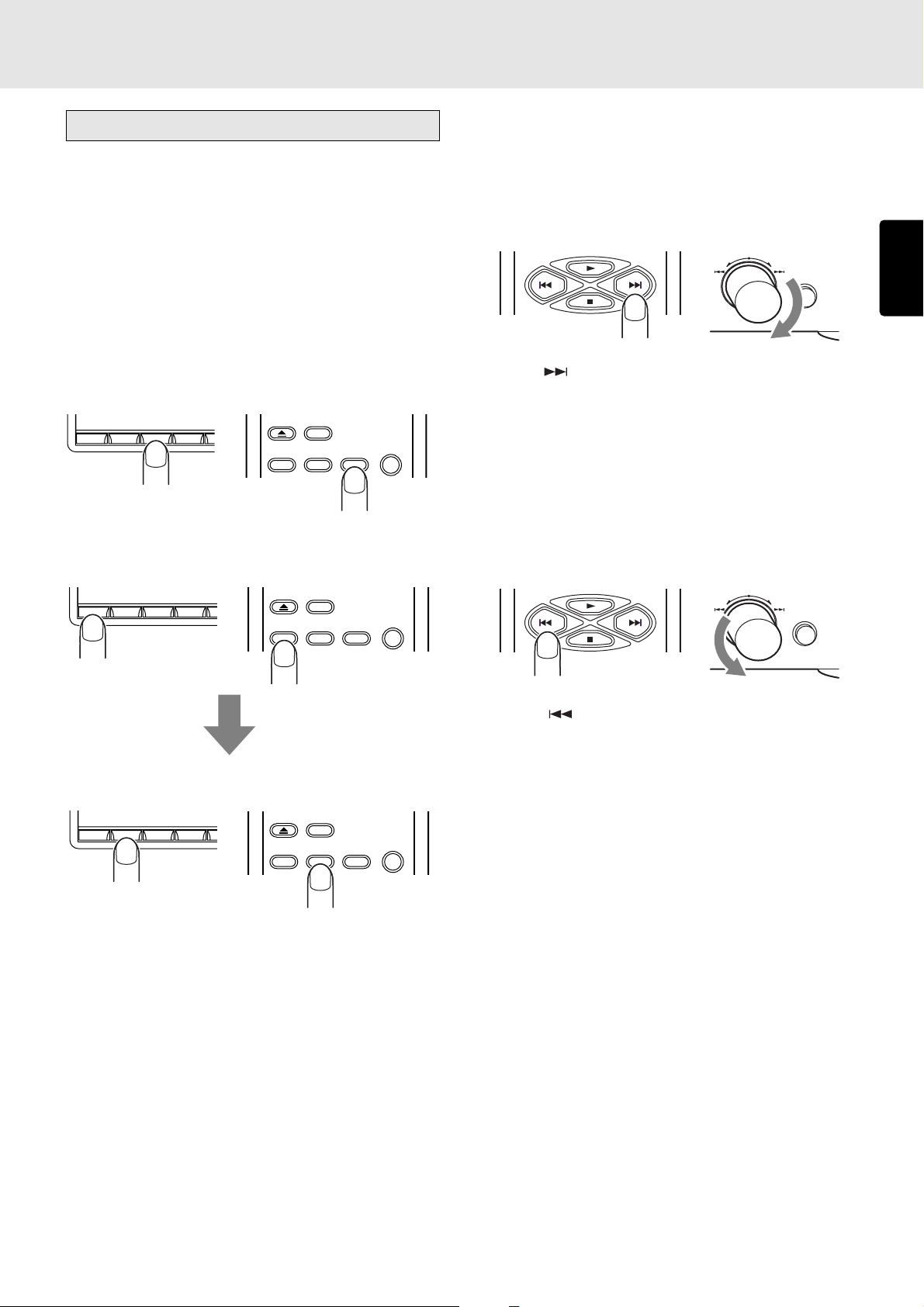
• Playing a previous or subsequent track
(track skip)
Advancing to a subsequent track
EASY JOG
QUICK REPLAY
ENGLISH
Press the button on the remote control unit for the number
of times equivalent to the number of tracks through which
play is to be advanced.
Play can also be advanced to the tracks ahead by turning
EASY JOG on the player clockwise. When EASY JOG is no
longer turned in the stop mode, the selected track is played
after one second elapses.
Returning to the start of the track now playing or a
previous track
EASY JOG
QUICK REPLAY
Within 1 second, press the “2” numeric button.
1
234
OPEN/
CLOSE
DISPLAY
12
REPEAT
3
Note:
* If a disc recorded with MP3 files also contains some data
files which are not MP3 files, the track before or after the
number of the selected track may be played. Direct
search is supported only for the album being played.
When the button on the remote control unit is pressed,
play returns to the start of the track now playing. Play returns
to the previous track which is equivalent to the number of
times the button was pressed.
In the same way, play can also be returned to the start of the
track now playing by turning EASY JOG dial on the player
counterclockwise. If it is turned further, play will return to the
previous track which is equivalent to the amount by which the
dial was turned.
When EASY JOG is no longer turned in the stop mode, the
selected track is played after one second elapses.
Note:
* If a disc recorded with MP3 files also contains some data
files which are not MP3 files, the track before or after the
number of the selected track may be played.
15
Page 20

BASIC OPERATIONS
Playing a specific part of a specific track
• Using the index function (index skip)
Q. REPLAY
SCROLL/
RECALL
TEXT
MENU ENTER
ENGLISH
INDEX
An index search can be performed during the play of a track
whose index has been recorded.
This function is useful for starting play at a specific location of
a long track. It returns play to a previous index which is
equivalent to the number of times the INDEX- button on the
remote control unit was pressed; alternatively, it advances
play to a subsequent index which is equivalent to the number
of times the INDEX+ button on the remote control unit was
pressed.
If the index skip function is operated for a CD with no indexes
recorded, the “No Index” message appears on the main
display, and play returns to the start of the track now playing.
Note:
* The index skip function cannot be used for discs
recorded with MP3 files.
The search (backward search) mode is established by holding
down the
button on the player or remote control unit.
During MP3 file play, play returns to the album title which is
equivalent to the number of times the button has been pressed.
Holding down the button initiates a backward search. (Returns
during backward searches are not constant.)
• Playing the last few seconds again during
play (quick replay)
Q. REPLAY
SCROLL/
RECALL
TEXT
PLAY/PAUSE
CUESTOP
PHONESLEVELQUICK REPLAY
+
-
MENU ENTER
INDEX
When the QUICK REPLAY button on the player or Q.REPLAY
button on the remote control unit is pressed during play, play
will be returned by the number of seconds set (factory setting
for quick replay time: 10 seconds), and the same section will
be played again. With a disc containing MP3 files, it will take
some moments for replay to begin.
For details on how to set the quick replay time. (See page
31.)
•
Searching a specific part of a track (search)
While listening to a track being played, it is possible to search
a specific part of that track by a forward or backward search.
Forward searching through the track now playing
CUESTOP
— +
ALBUM
EASY JOG
0
QUICK REPLAY
TIME
The search (forward search) mode is established by holding
down the
button on the player or remote control unit.
During MP3 file play, play advances to the album title which
is equivalent to the number of times the button has been
pressed. Holding down the button initiates a forward search.
Backward searching through the track now playing
CUESTOP
— +
ALBUM
EASY JOG
0
QUICK REPLAY
TIME
Note:
* The quick replay key on the play function menu must be
set to “Quick Replay.” (Factory setting: Quick Replay)
Refer to “How to set the quick replay key” (page 32).
• Listening to the end of a track (end monitor)
Q. REPLAY
SCROLL/
RECALL
TEXT
PLAY/PAUSE
CUESTOP
PHONESLEVELQUICK REPLAY
+
-
MENU ENTER
INDEX
When the unit’s QUICK REPLAY button or the remote
controller’s Q.REPLAY button is pressed during play, play is
resumed from the position which is before the end position of
the track now playing by the number of seconds which have
been set (factory setting for quick replay time: 10 sec.).
Note:
* The quick replay key on the play function menu must be
set to “End Monitor.” (Since the key was set to Quick
Replay at the factory, set it to End Monitor prior to
operation.)
Refer to “How to set the quick replay key” (page 32).
* With discs recorded with MP3 files, the quick play
operation is performed even if the quick replay key is
set to “End Monitor.”
16
Page 21

7. ADVANCED OPERATIONS
Repeat play (playing the same
tracks repeatedly)
• Playing all tracks repeatedly (all-track
repeat)
This function repeatedly plays all the tracks. Repeat play is
possible even during random play or program play.
Press the REPEAT button on the remote control unit.
OPEN/
CLOSE
DISPLAY
REPEAT
12
The “RPT” indicator on the display lights, and the repeat play
of all the tracks starts.
TTL
TRK INDX
12 34 56 78 910 1112 1314 1516 1718
To stop all-track repeat play and resume normal play, press
the REPEAT button on the remote control unit twice. The “RPT”
indicator on the display goes off.
All-track repeat play can also be initiated using EASY JOG
on the player. (See page 29.)
3
RPT
TIME
• Playing a specific part repeatedly (A-B
repeat)
This function repeatedly plays a specific part of a track that
you want to hear.
1. During play, press the A-B button on the remote control
unit at the start point of the part to be repeated.
RANDOM
978
PROGRAM
0
CANCEL
A-B
The “A-” indicator on the display now lights.
Display example: A-B repeat , point A (start), track 1, 5 sec.
A
TRK INDX
—
TIME
TTL
12 34 56 78 910 1112 1314 1516 1718
2. Press the A-B button on the remote control unit at the end
point of the part to be repeated.
RANDOM
978
ENGLISH
• Playing one track repeatedly (1-track
repeat)
This function repeatedly plays one track only. Even during
random play or program play, it repeats the track being played.
Press the REPEAT button on the remote control unit twice while
the track to be repeated is playing.
OPEN/
CLOSE
DISPLAY
REPEAT
RPT
3
1
TIME
12
The “RPT” and “1” indicators light, and track now playing is
repeated.
TTL
TRK INDX
12 34 56 78 910 1112 1314 1516 1718
To stop 1-track repeat play and resume normal play, press
the REPEAT button on the remote control unit to turn off the
“RPT” indicator on the display. 1-track repeat play can also
be initiated using EASY JOG on the player. (See page 29.)
PROGRAM
0
CANCEL
A-B
The “A-B” indicator on the display now lights, and the
designated part (from point A to point B) is played
repeatedly.
Display example: A-B repeat , point B (end), track 1, 20 sec.
TTL
12 34 56 78 910 1112 1314 1516 1718
A — B
TRK INDX
TIME
To stop A-B repeat play and resume normal play, press the AB button on the remote control unit to turn off the “A-B” indicator
on the display.
Note:
* The A-B repeat play function cannot be used during
random play or program play. Neither can it be used
with discs on which MP3 files have been recorded.
17
Page 22
ADVANCED OPERATIONS
Random play (Playing tracks in a
random sequence)
This function rearranges the tracks into a random sequence
and it then plays all the tracks in this random sequence. If it
ENGLISH
is used together with repeat play, the same tracks can be
repeatedly played but in a different sequence every time.
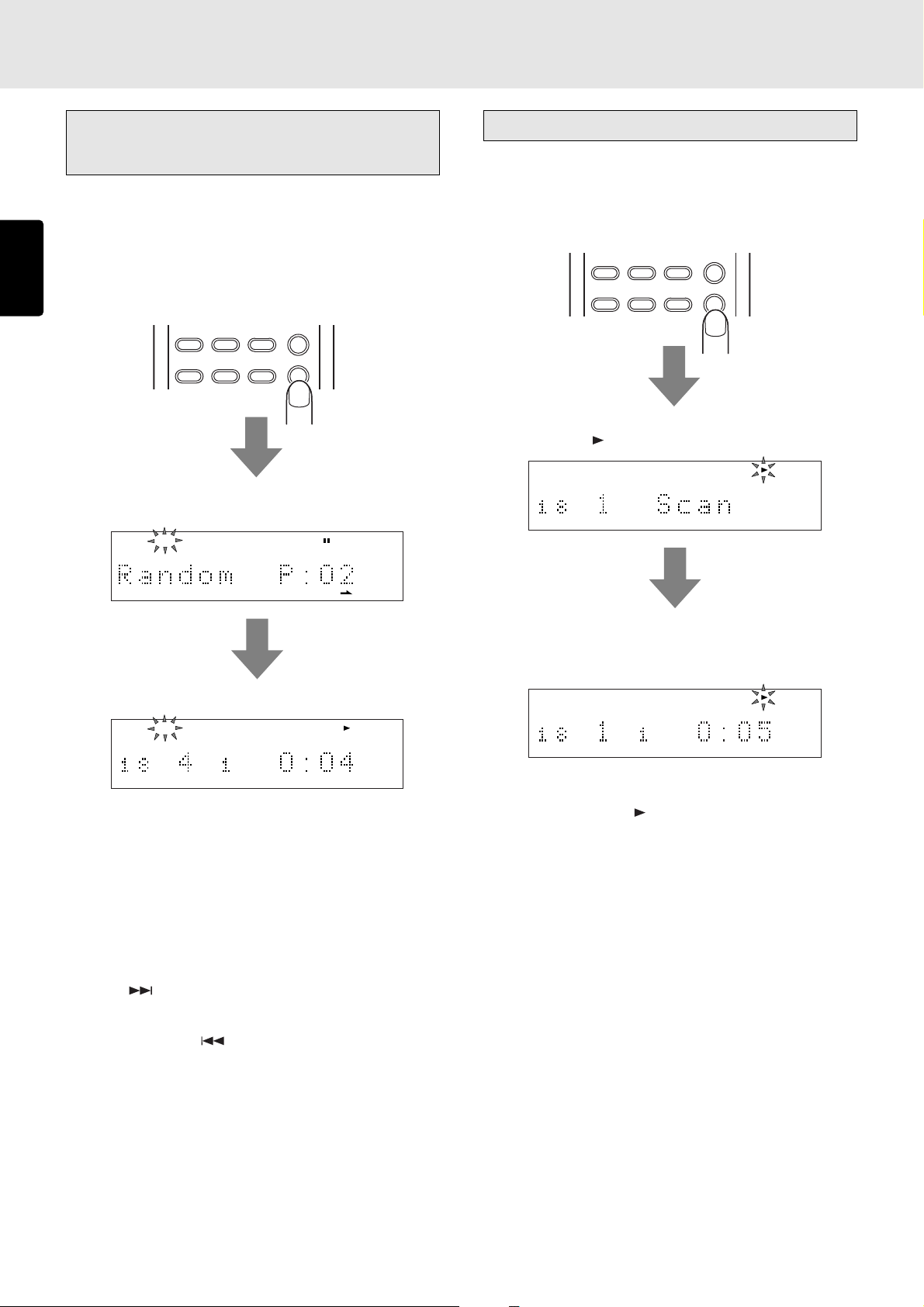
During play or stop, press the RANDOM button on the remote
control unit.
AMS
654
RANDOM
978
The items on the music calendar appear on the display one
after the other, and the “RNDM” indicator lights.
RNDM
AMS play (Searching for a specific track)
This function comes in handy when searching for a specific
track that you want to hear.
During stop or play, press the AMS (auto music scan) button
on the remote control unit.
REPEAT
12
The total number of tracks, track “1” and “SCAN” light on the
display, and the “
12 34 56 78 910 1112 1314 1516 1718
” indicator flashes.
3
AMS
654
78 910 1112 1314
Random play now starts.
RNDM
TTL
TRK INDX
12 34 56 78 910 1112 1314 1516 17
TIME
To stop random play and resume normal play, press the
RANDOM button on the remote control unit. The “RNDM”
indicator on the display goes off.
Random play can also be initiated using EASY JOG on the
player. (See page 30.)
• Skipping tracks during random play to
search other tracks
When the button on the remote control unit is pressed or
EASY JOG on the player is turned clockwise during random
play, the next track is selected at random and played.
Conversely, when the
pressed or EASY JOG on the player is turned counterclockwise
during random play, play returns to the start of the track now
playing. If the same operation is repeated, play is initiated in
the reverse order in which the tracks were played.
button on the remote control unit is
The intros of all the tracks starting from track 1 are played in
succession for the duration which has been set (factory
setting: 10 seconds).
TTL
TRK INDX
12 34 56 78 910 1112 1314 1516 1718
TIME
Once the track you want to hear has been found, press the
AMS button again. The “
” indicator now lights, and the track
found and whatever comes after that track will now be played
normally.
When the RANDOM button on the remote control unit is
pressed during AMS play, the AMS play function is released,
and the random play mode is established.
AMS play can also be initiated using EASY JOG on the player.
(See page 31.)
18
Page 23
ADVANCED OPERATIONS
Program play (playing tracks in the
preferred sequence)
The order in which the CD tracks are played can be rearranged
into the sequence desired. Up to 30 tracks can be
programmed.
• Program play in the time display mode
In the case of a CD-TEXT disc, first press the TIME button on
the remote control unit to set the main display to the time
display mode.
TIME
TTL
TEXT
12 34 56 78 910 1112 1314 1516 1718
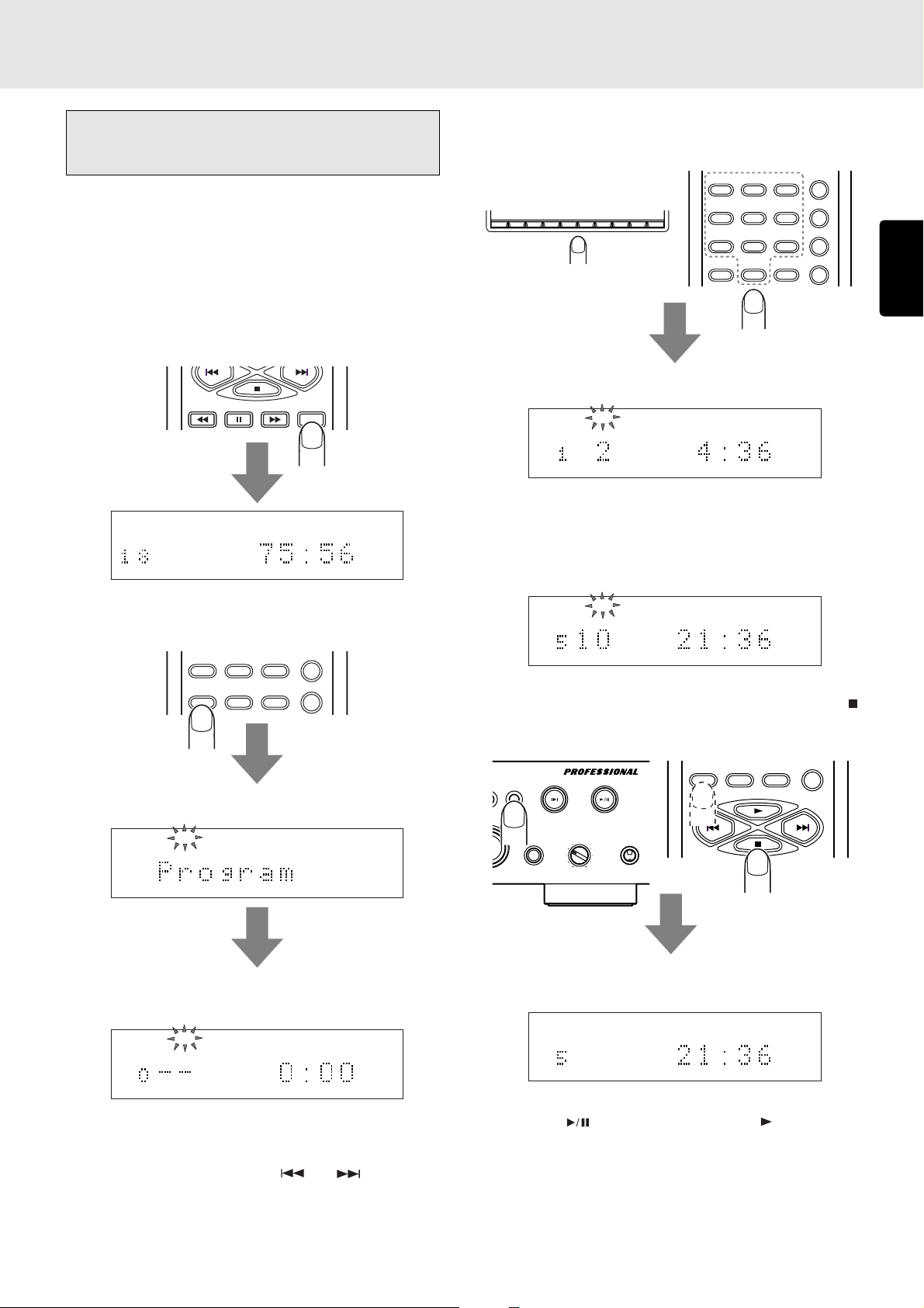
1. During stop, press the PROGRAM button on the remote
control unit.
978
RANDOM
TTL
TIME
REPEAT
3
AMS
654
RANDOM
978
A-B
CANCEL
0
1
23456789
12
0
PROGRAM
Display example: When track 2 has been selected
PROG
TTL
TEXT
TRK
2
TTL
TIME
3. Repeat step 2 to program the desired tracks in sequence.
At each step of the programming, the number of tracks
programmed and their total time appear on the main
display. Up to 30 tracks can be programmed.
PROG
TTL
TRK
TEXT
246810
TTL
TIME
ENGLISH
PROGRAM
0
CANCEL
A-B
“Program” appears for an instant on the main display.
PROG
TEXT
The PROG indicator flashes, and the program mode is
established.
PROG
TTL
TEXT
TTL
TIME
2. Press the numeric buttons on the remote control unit or
player that correspond to the track numbers (the tracks
can also be selected using the
select track number 10 or above, use the numeric buttons
to select the higher digit first and then select the lower
digit.
and buttons). To
4. Once all the tracks have been programmed, press the
button on the player or remote control unit or press the
PROGRAM button on the remote control unit.
PLAY/PAUSE
CUESTOP
OG
PHONESLEVELQUICK REPLAY
+
-
PROGRAM
0
CANCEL
A-B
The PROG indicator stops flashing and lights up instead,
and the program is entered.
PROG
TTL
TEXT
246810
TTL
TIME
5. Press the button on the player or the button on the
remote control unit. Play now starts in the programmed
sequence.
Program play will start even when step
4 is omitted.
Program play can also be initiated using EASY JOG on
the player. (See page 30.)
19
Page 24
ADVANCED OPERATIONS
• Program play in the text display mode
In the case of a CD-TEXT disc, tracks can be selected by title
for program play.
If the main display is set to the time display mode, press the
TEXT button on the remote control unit to establish the text
ENGLISH
display mode.
TIME
TEXT
MENU ENTER
TEXT
12 34 56 78 910 1112 1314 1516 1718 19
SCROLL/
RECALL
1. During stop, press the PROGRAM button on the remote
control unit.
RANDOM
978
The title of each selected track is scrolled, and once it
has been scrolled, it is programmed automatically. If you
do not want to program the track, select another track
before the scrolling is completed.
TEXT
3. Repeat step 2 to program the desired tracks in sequence.
Up to 30 tracks can be programmed.
4. Once all the tracks have been programmed, press the
button on the player or remote control unit or press the
PROGRAM button on the remote control unit.
PLAY/PAUSE
CUESTOP
OG
PHONESLEVELQUICK REPLAY
+
-
PROGRAM
0
CANCEL
A-B
PROGRAM
0
CANCEL
A-B
“Program” appears for an instant on the main display. Then
the PROG indicator flashes, and the program mode is
established.
PROG
TEXT
2. Press the and buttons on the remote control unit
or use EASY JOG on the player to select the track. (The
track can also be selected using the numeric buttons but
in this case the title is not displayed).
EASY JOG
QUICK REPLAY
The PROG indicator stops flashing and lights up instead,
and the program is entered.
PROG
TTL
246810
TTL
TIME
5. Press the button on the player or the button on the
remote control unit. Play of the selected tracks now starts
in the programmed sequence.
Program play will start even when step
Program play can also be initiated using EASY JOG on
the player. (See page 30.)
Note:
* Programming in the text display mode cannot be
performed for tracks which have no text information for
their titles.
4 is omitted.
20
Page 25
ADVANCED OPERATIONS
Delete program play (play with
undesired tracks skipped)
This function makes it possible to skip those tracks that you
do not want to hear during CD play. Up to 30 tracks can be
deleted from the program.
• Delete program play in the time display
mode
In the case of a CD-TEXT disc, first press the TIME button on
the remote control unit to set the main display to the time
display mode.
TIME
TTL
TEXT
12 34 56 78 910 1112 1314 1516 1718
TTL
TIME
1. During stop, press the PROGRAM button on the remote
control unit, and then press the CANCEL button.
RANDOM
978
PROGRAM
0
CANCEL
A-B
2. Press the numeric buttons on the remote control unit or
player that correspond to the track number that you do
not want to hear (the track can also be selected using the
and buttons).
REPEAT
3
AMS
654
RANDOM
978
A-B
CANCEL
0
1
23456789
12
0
PROGRAM
Display example: When track 2 has been selected
PROG
TTL
TRK
TEXT
1 3 4 5 6 7 8 9 10 11 12 13 14 15 16 17 18
TTL
TIME
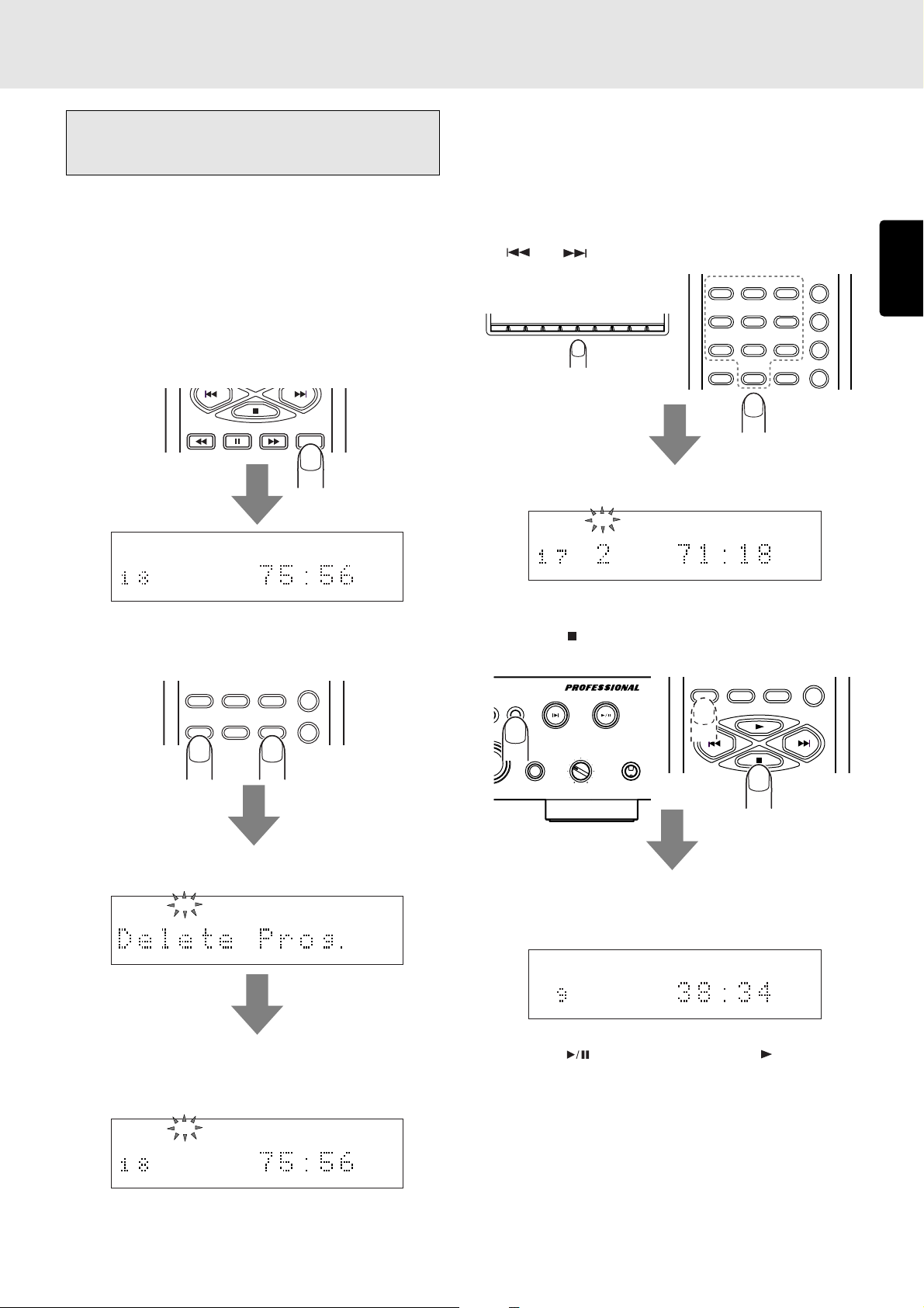
3. Repeat step 2, and upon completion of the programming,
press the
press the PROGRAM button on the remote control unit.
OG
button on the player or remote control unit or
PLAY/PAUSE
CUESTOP
PHONESLEVELQUICK REPLAY
PROGRAM
CANCEL
0
A-B
ENGLISH
“Delete Prog.” appears for an instant on the main display.
PROG
TEXT
12 34 56 78 910 1112 1314 1516 1718 19
The total number of CD tracks and the total play time
appear on the main display, the PROG indicator flashes,
and the delete program mode is established.
PROG
TTL
TEXT
12 34 56 78 910 1112 1314 1516 1718
TTL
TIME
+
-
The PROG indicator in the display stops flashing and lights
up instead, and the delete program is entered. Up to 30
tracks can be deleted from the program.
PROG
TTL
TEXT
1357911131517
TTL
TIME
4. Press the button on the player or the button on the
remote control unit. The CD is now played but with the
deleted tracks skipped.
Delete program play can also be initiated using EASY JOG
on the player. (See page 30.)
21
Page 26

ADVANCED OPERATIONS
• Delete program play in the text display
mode
In the case of a CD-TEXT disc, the tracks that are not desired
can be selected by title for delete program play.
If the main display is set to the time display mode, press the
ENGLISH
TEXT button on the remote control unit to establish the text
display mode.
TIME
TEXT
MENU ENTER
TEXT
12 34 56 78 910 1112 1314 1516 1718 19
SCROLL/
RECALL
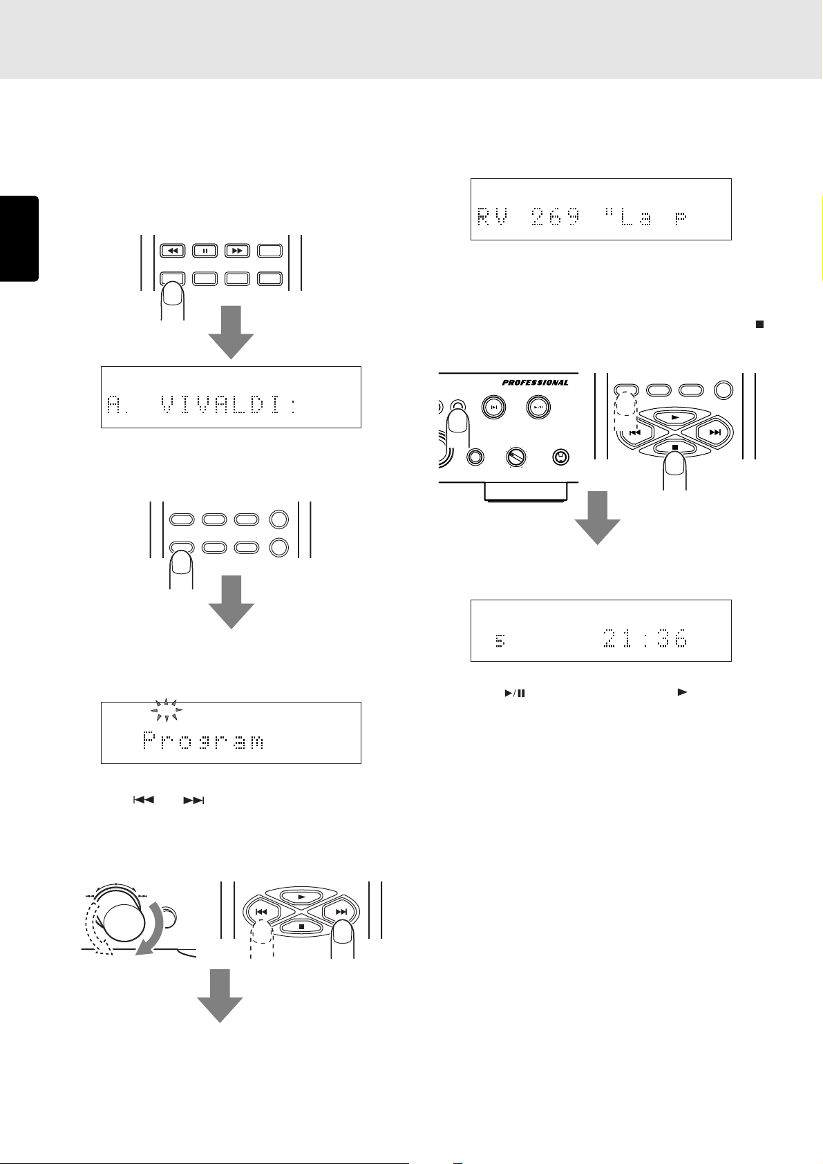
2. Press the and buttons on the remote control unit
or use EASY JOG on the player to select the track which
you do not want to hear. (The tracks can also be selected
using the numeric buttons but in this case the titles will
not be displayed.)
EASY JOG
QUICK REPLAY
The title of each selected track is scrolled, and once it
has been scrolled, it is deleted automatically. If you do
not want to delete the track, select another track before
the scrolling is completed.
1. During stop, press the PROGRAM button on the remote
control unit, and then press the CANCEL button.
RANDOM
978
PROGRAM
0
“Delete Prog.” appears for an instant on the main display.
PROG
TEXT
12 34 56 78 910 1112 1314 1516 1718 19
The total number of CD tracks and the album title appear
on the main display, the PROG indicator flashes, and the
delete program mode is established.
PROG
TTL
TEXT
12 34 56 78 910 1112 1314 1516 1718 19
CANCEL
A-B
TTL
TIME
PROG
TEXT
2 3 4 5 6 7 8 9 10 11 12 13 14 15 16 17 18 19
3. Repeat step 2, and upon completion of the programming,
press the button on the player or remote control unit or
press the PROGRAM button on the remote control unit.
PLAY/PAUSE
CUESTOP
OG
PHONESLEVELQUICK REPLAY
+
-
PROGRAM
0
CANCEL
A-B
The PROG indicator in the display stops flashing and lights
up instead, and the delete program is entered. Up to 30
tracks can be deleted from the program.
PROG
TTL
TEXT
1357911131517
TTL
TIME
4. Press the button on the player or the button on the
remote control unit. The CD is now played but with the
deleted tracks skipped.
Delete program play can also be initiated using EASY JOG
on the player. (See page 30.)
22
Note:
* Delete programming in the text display mode cannot be
performed for tracks which have no text information for
their titles.
Page 27

ADVANCED OPERATIONS
• Checking the program or delete program
contents
TIME
TEXT
MENU ENTER
SCROLL/
RECALL
During programming operation or program play, press the
SCROLL/RECALL button on the remote control unit.
With program play, the programmed tracks are displayed one
after the other in sequence on the main display.
With delete program play, the deleted tracks are displayed
one after the other in sequence on the main display.
• Changing the program or delete program
contents
PROGRAM
TEXT
0
MENU ENTER
CANCEL
A-B
TIME
SCROLL/
RECALL
• Returning program play to normal play
(canceling the entire program)
PLAY/PAUSE
CUESTOP
OG
PHONESLEVELQUICK REPLAY
+
-
Press the button on the player or remote control unit twice
during program play or once during stop. The PROG indicator
on the display goes off, and the entire program is canceled.
LAYER PMD325
Alternatively, a program can be canceled when the disc tray
is opened by pressing the OPEN/CLOSE button on the
player or remote control unit.
Adding tracks to the program
OPEN/CLOSE
OPEN/
CLOSE
DISPLAY
RANDOM
978
ENGLISH
Deleting tracks which were programmed for program
play
When the SCROLL/RECALL button on the remote control unit
is pressed during programming, the programmed tracks are
displayed one after the other in sequence.
As soon as the track to be deleted from the program has
appeared, press the CANCEL button on the remote control
unit immediately. The number of the deleted track is cleared
from the music calendar on the display.
Canceling the deletion of tracks which were deleted
for delete program play
When the SCROLL/RECALL button on the remote control unit
is pressed during delete programming, the deleted tracks are
displayed one after the other in sequence.
As soon as the track whose deletion is to be canceled has
appeared, press the CANCEL button on the remote control
unit immediately. The number of the track whose deletion
was canceled is displayed in the music calendar on the
display.
PROGRAM
0
CANCEL
A-B
Press the PROGRAM button on the remote control unit during
stop. The status of the PROG indicator in the display changes
from lighted to flashing, and more tracks can be added to the
program.
• Precautions for program and delete
program play
The program play and delete program play functions
∗
cannot be used with discs on which MP3 files have been
recorded.
When using the numeric buttons to select tracks 1 to 9 on
∗
a CD with 10 or more tracks in total, allow 1.5 seconds or
so to elapse after the button corresponding to the number
of the previous track was pressed before pressing the
button corresponding to the number of the next track.
When using the numeric buttons to select track 10 or up
∗
on a CD with 10 or more tracks in total, press the button
corresponding to lower digit within 1.5 seconds or so after
the button corresponding to the higher digit was pressed.
When using the and buttons for programming,
∗
keep pressing one of these buttons with less than half a
second or so in between until the number of the desired
track is displayed.
If the total time for a program exceeds 99 minutes, the time
∗
display will appear as “– – : – –.”
23
Page 28

ADVANCED OPERATIONS
Pitch control
(changing the play speed)
The play speed (pitch) can be changed across a ±12% range.
Digital signals are not output during pitch control.
∗
ENGLISH
• Increasing the play speed
Press the PITCH+ button on the remote control unit.
INDEX
Q. REPLAY
PITCH
RESET
Each time the button is pressed, the play speed is increased
in 1% increments (up to a maximum of +12%), and it is
displayed on the main display.
12 34 56 78 910 1112 1314 1516 1718
• Reducing the play speed
Press the PITCH- button on the remote control unit.
• Returning play to the normal speed (0%)
Press the PITCH RESET button on the remote control unit.
INDEX
“Pitch: 0%” appears on the main display.
12 34 56 78 910 1112 1314 1516 1718
If the PITCH RESET button on the remote control unit is pressed
again, play returns to the previous speed setting.
Pitch control can also be performed using EASY JOG on the
player. (See page 27.)
Q. REPLAY
PITCH
RESET
INDEX
Q. REPLAY
PITCH
RESET
Each time the button is pressed, the play speed is reduced in
1% increments (up to a minimum of -12%), and it is displayed
on the main display.
12 34 56 78 910 1112 1314 1516 1718
24
Page 29

ADVANCED OPERATIONS
Setting the position to start
listening to play (manual cue)
If the play start position is set ahead of time, you can start
listening to the disc from the position which was set at any time.
• Setting the cue point (play start position)
1. Play the part at the approximate position of the cue point
which is to be set, and press the
to the pause mode.
2. Press the CUE button.
CUESTOP
— +
ALBUM
EASY JOG
-
The frame display now appears on the display window,
and the cue point setting mode is established.
TTL
TRK
button to set the unit
PLAY/PAUSE
PHONESLEVELQUICK REPLAY
+
TIME
Once the cue point has been set, the position where it
was set will be retained in the memory until the power is
turned off or the CD is removed. To set a new cue point,
repeat the procedure from step
1.
Note:
* The cue point cannot be set if a disc recorded with MP3
files is used.
• Listening from the cue point (play start
position)
1. Press the CUE button while operation is stopped or during
play. Play now moves to the cue point, and the unit is set
to the pause mode.
PLAY/PAUSE
CUESTOP
— +
ALBUM
EASY JOG
PHONESLEVELQUICK REPLAY
+
-
The position where the cue point was set now appears on
the display window, and the time flashes.
ENGLISH
12 34 56 78 910 1112 1314 1516 1718
(The index display is cleared at this time.)
3. Turn EASY JOG or press the or button to finely
adjust the cue point.
When EASY JOG is turned clockwise, the frames are
advanced one at a time; conversely, when it is turned
counterclockwise, they are returned one at a time.
When the
forward status; conversely, when the
button is held down, play is set to the fast
button is held
down, play is set to the fast backward status.
4. Press EASY JOG to enter the cue point. “Cue Point”
appears for an instant on the display window.
12 34 56 78 910 11
The time at which the cue point was set now flashes, and
the unit is set to the pause mode. If the procedure is
repeated from step
point can now be set.
2 in this mode, a slightly different cue
TTL
TRK INDX
12 34 56 78 910 11
TTL
TIME
2. Press the button. Play now starts from the cue point.
Once the cue point has been set, play can be returned to
the cue point at any time simply by pressing the CUE point
during play.
TTL
TRK INDX
12 34 56 78 910 11
TTL
TIME
25
Page 30

8. SETTING THE PLAY FUNCTIONS
Using EASY JOG
The front panel of the player features the EASY JOG dial to
facilitate a number of different operations to be performed.
Under normal circumstances, play re-starts at the start of the
previous or subsequent tracks by turning the dial clockwise
ENGLISH
or counterclockwise. The dial also enables the play functions
(play modes) to be set from the menu. The menu can also be
operated from the remote control unit.
• Setting the play functions (play modes)
EASY JOG
QUICK REPLAY
When EASY JOG is pressed or when the MENU button on the
remote control unit is pressed, the play function (play mode)
setting mode is established.
EASY JOG
QUICK REPLAY
TEXT
MENU ENTER
TIME
SCROLL/
RECALL
Shown below is the play function (play mode) menu which is
switched when EASY JOG is turned.
1
2
3
4
5
6
7
8
9
10
11
Pitch
Single Track Play
Auto Cue
Repeat
Program
Delete Program
Random
AMS Time
Quick Replay Time
Quick Replay Key
Timer Play
EASY JOG turned
clockwise or
or MENU button
pressed
When EASY JOG is turned clockwise or counterclockwise in
this mode, the play function menu is switched.
The play function (play mode) menu can also be switched by
pressing the MENU button or the
or button on the
remote control unit.
EASY JOG
QUICK REPLAY
TEXT
MENU ENTER
TIME
SCROLL/
RECALL
At the desired play function (play mode), either press EASY
JOG on the player or press the ENTER button on the remote
control unit to select the mode concerned.
For subsequent details on the play functions (play modes),
refer to pages 27 to 37.
12
Play Mode
EASY JOG turned
13
Time Mode
counterclockwise
or button
pressed
14
15
16
17
18
19
20
Text Mode
End Warning
Tray Lock
Key Lock
MP3 Load
Auto MP3 Load
Default
While one of the play functions is being selected, the number
of the function as given in the figure above is displayed on
the music calendar.
26
Page 31

SETTING THE PLAY FUNCTIONS
• Pitch
This function enables the play speed (pitch) to be adjusted
within a +/-12% range. The setting is restored to “0%” when
the disc is replaced.
1. Press EASY JOG and then turn it so that “Pitch” appears
on the main display.
2. Press EASY JOG (or press the ENTER button on the remote
control unit) to select Pitch Control.
ENGLISH
EASY JOG
QUICK REPLAY
TEXT
MENU ENTER
TIME
SCROLL/
RECALL
3. Turn EASY JOG (or press the or button on the
remote control unit).
EASY JOG
QUICK REPLAY
The pitch control setting now appears on the main display.
The factory setting is 0% but this can be increased (to a
maximum of +12%) by turning EASY JOG clockwise or
reduced (to a minimum of -12%) by turning it
counterclockwise.
Minimum
Maximum
4. Set the play speed (pitch), and press EASY JOG (or press
the ENTER button on the remote control unit) to enter the
setting.
EASY JOG
QUICK REPLAY
TEXT
MENU ENTER
TIME
SCROLL/
RECALL
27
Page 32
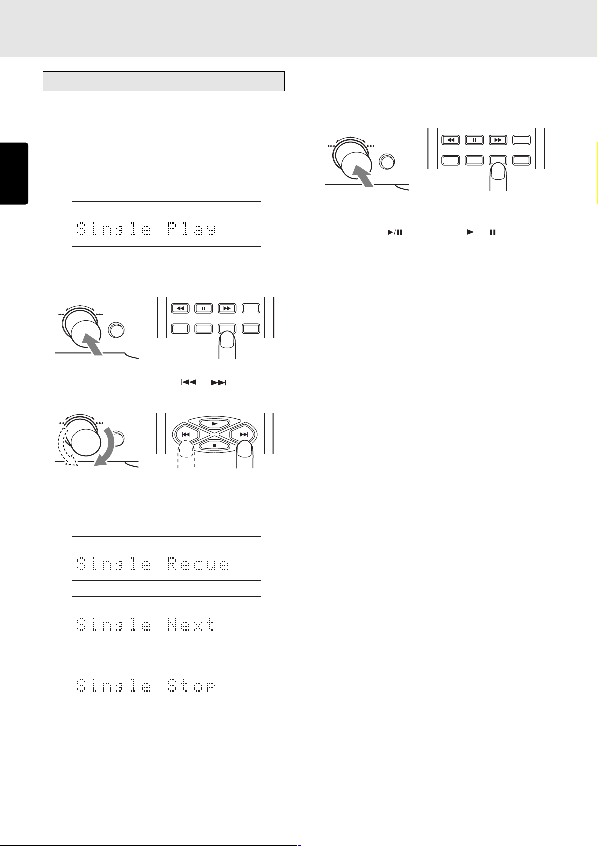
SETTING THE PLAY FUNCTIONS
QUICK REPLAY
EASY JOG
Various play functions (play modes)
• Single Track Play (ON/OFF)
This function enables single play searches which come in
handy at such times as practicing musical performances or
using the player at broadcast facilities.
ENGLISH
1. Press EASY JOG and then turn it so that “Single Play”
appears on the main display.
2. Press EASY JOG (or press the ENTER button on the remote
control unit) to select Single Track Play.
EASY JOG
QUICK REPLAY
TEXT
MENU ENTER
TIME
SCROLL/
RECALL
4. When EASY JOG (or the ENTER button on the remote
control unit) is pressed, the mode now displayed is
entered. When Single Recue, Single Next or Single Stop
has been selected, “S.PLAY” lights on the display window.
TIME
TEXT
MENU ENTER
When Single Recue or Single Next is set, play stops
temporarily at the start of the track and stands by.
Use the unit’s
button (or the or button on the
remote control unit) to start play.
At the Single Recue setting, play stops temporarily at the
start of the track now playing when that track is finished,
at the Single Next setting, it stops temporarily at the start
of the next track when the track now playing is finished;
and at the Single Stop setting, play stops when the track
now playing is finished.
SCROLL/
RECALL
3. Turn EASY JOG (or press the or button on the
remote control unit).
EASY JOG
QUICK REPLAY
The play mode is selected in succession through a 4-step
cycle: Single Recue → Single Next → Single Stop → Single
Off → Single Recue.
28
Page 33

QUICK REPLAY
EASY JOG
QUICK REPLAY
EASY JOG
SETTING THE PLAY FUNCTIONS
Auto Cue (ON/OFF)
This function enables a blank part at the beginning of a track
to be skipped and play to start where the sound has been
recorded.
1. Press EASY JOG and then turn it to display “Auto Cue” on
the main display.
2. Press EASY JOG (or the ENTER button on the remote
control unit), and select “Auto Cue.”
EASY JOG
QUICK REPLAY
TEXT
MENU ENTER
TIME
SCROLL/
RECALL
3. Press EASY JOG (or the or button on the remote
control unit).
EASY JOG
QUICK REPLAY
• Repeat (ALL/1/OFF)
This function enables some or all of the tracks on a disc to be
played repeatedly.
1. Press EASY JOG and then turn it so that “Repeat” appears
on the main display.
2. Press EASY JOG (or press the ENTER button on the remote
control unit) to select Repeat.
TIME
TEXT
MENU ENTER
SCROLL/
RECALL
3. Turn EASY JOG (or press the or button on the
remote control unit).
EASY JOG
QUICK REPLAY
ENGLISH
“Auto Cue: ON” and “Auto Cue: OFF” are displayed
alternately on the main display.
4. When EASY JOG (or the ENTER button on the remote
control unit) is pressed while “Auto Cue: ON” is displayed,
the auto cue function is enabled.
EASY JOG
QUICK REPLAY
When auto cue is set to ON, the blank part at the beginning
of the track is skipped, and the unit is set to the pause
mode at the position where the sound is recorded and it
stands by for play.
Use the unit’s
button to start play from the position
where the sound is recorded.
Note:
* The auto cue function does not work even when auto
cue has been set to ON if a disc recorded with MP3 files
is used.
TEXT
MENU ENTER
TIME
SCROLL/
RECALL
The function is switched through three settings:
“Repeat:ALL” (all-track repeat) → “Repeat:1” (1-track
repeat) → “Repeat OFF” → “Repeat:ALL.”
4. Press EASY JOG (or press the ENTER button on the remote
control unit) to enter the displayed status.
TIME
TEXT
MENU ENTER
SCROLL/
RECALL
At the “Repeat:ALL” (all-track repeat) setting, all the tracks
on the CD are played repeatedly; at the “Repeat:1” (1track repeat) setting, one track is played repeatedly.
29
Page 34

SETTING THE PLAY FUNCTIONS
QUICK REPLAY
EASY JOG
QUICK REPLAY
EASY JOG
• Program
This function enables the tracks to be rearranged into the
desired sequence for play.
Press EASY JOG and then turn it so that “Program” appears
on the main display.
ENGLISH
Press EASY JOG (or press the ENTER button on the remote
control unit) to select Program.
EASY JOG
QUICK REPLAY
The PROG indicator flashes on the display, and the tracks
can be rearranged in the desired sequence.
Turning EASY JOG clockwise executes the same function as
NEXT
(the track number is incremented); conversely,
turning it counterclockwise executes the same function as
PREVIOUS
(the track number is decremented). The
program settings are the same as the ones on page 19.
The program function cannot be used with discs on which
MP3 files have been recorded.
TEXT
MENU ENTER
TIME
SCROLL/
RECALL
• Random (ON/OFF)
This function enables the tracks to be rearranged in a random
sequence and played.
1. Press EASY JOG and then turn it so that “Random”
appears on the main display.
2. Press EASY JOG (or press the ENTER button on the remote
control unit) to select Random.
TIME
TEXT
MENU ENTER
SCROLL/
RECALL
3. Turn EASY JOG (or press the or button on the
remote control unit).
EASY JOG
QUICK REPLAY
• Delete Program
This function makes it possible to play the CD with the tracks
that are not desired skipped.
Press EASY JOG and then turn it so that “Delete Prog.”
appears on the main display.
Press EASY JOG (or press the ENTER button on the remote
control unit) to select Delete Program.
EASY JOG
QUICK REPLAY
TEXT
MENU ENTER
The PROG indicator flashes on the display, the total number
of tracks and the total play time are displayed, and the tracks
which are not going to be played can be selected.
Turning EASY JOG clockwise executes the same function as
NEXT
(the track number is incremented); conversely,
turning it counterclockwise executes the same function as
PREVIOUS
(the track number is decremented). The
delete program settings are the same as the ones on page
21.
Note:
* The delete program function cannot be used with discs
on which MP3 files have been recorded.
30
TIME
SCROLL/
RECALL
“Random:ON” and “Random:OFF” appear alternately on
the main display.
4. When EASY JOG (or the ENTER button on the remote
control unit) is pressed while “Random: ON” is displayed,
the “RNDM” indicator lights, the tracks are rearranged in
a random sequence, and all the tracks are played.
TIME
TEXT
MENU ENTER
SCROLL/
RECALL
Page 35

SETTING THE PLAY FUNCTIONS
QUICK REPLAY
EASY JOG
QUICK REPLAY
EASY JOG
• AMS (Auto Music Scan) Time
The AMS function enables the intros of all the tracks starting
from track 1 to be played for the duration which has been set
one after the other. In the case of this player, it enables the
intro play time to be set.
1. Press EASY JOG and then turn it so that “AMS Time”
appears on the main display.
2. Press EASY JOG (or press the ENTER button on the remote
control unit) to select AMS Time.
EASY JOG
QUICK REPLAY
TEXT
MENU ENTER
TIME
SCROLL/
RECALL
3. Turn EASY JOG (or press the or button on the
remote control unit).
EASY JOG
QUICK REPLAY
• Quick Replay Time
This is used to set the number of seconds for Quick Replay or
End Monitor.
1. Press EASY JOG and then turn it so that “Q.ReplayTime”
appears on the main display.
2. Press EASY JOG (or press the ENTER button on the remote
control unit) to select Quick Replay Time.
TIME
TEXT
MENU ENTER
SCROLL/
RECALL
3. Turn EASY JOG (or press the or button on the
remote control unit).
EASY JOG
QUICK REPLAY
ENGLISH
The AMS play time setting now appears on the main
display. The factory setting is 10 seconds but this can be
increased (to a maximum of 30 seconds) by turning EASY
JOG clockwise or reduced (to a minimum of 3 seconds)
by turning it counterclockwise.
Minimum
Maximum
4. Set the time, and press EASY JOG (or press the ENTER
button on the remote control unit) to enter the setting and
start AMS play.
EASY JOG
QUICK REPLAY
TEXT
MENU ENTER
TIME
SCROLL/
RECALL
The quick replay time setting now appears on the main
display. The factory setting is 10 seconds but this can be
increased (to a maximum of 30 seconds) by turning EASY
JOG clockwise or reduced (to a minimum of 1 second) by
turning it counterclockwise.
Minimum
Maximum
4. When the time (number of seconds) for Quick Replay or
End Monitor is set and then EASY JOG (or the ENTER
button on the remote control unit) is pressed, the setting
is entered.
TIME
TEXT
MENU ENTER
SCROLL/
RECALL
31
Page 36
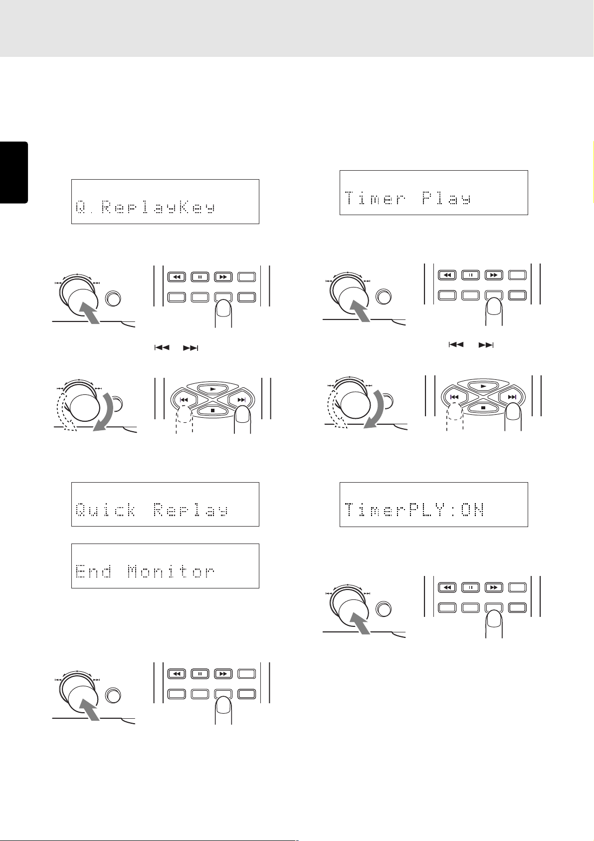
SETTING THE PLAY FUNCTIONS
QUICK REPLAY
EASY JOG
QUICK REPLAY
EASY JOG
• Quick Replay Key (Quick Replay/End
Monitor)
This function is used to switch the function when the unit’s
QUICK REPLAY button (and the Q.REPLAY button on the
remote control unit) has been pressed.
ENGLISH
1. Press EASY JOG and then turn it to display “Q.Replay” on
the main display.
2. Press EASY JOG (or the ENTER button on the remote
control unit), and select “Q.ReplayKey.”
EASY JOG
QUICK REPLAY
TEXT
MENU ENTER
3. Press EASY JOG (or the or button on the remote
control unit).
EASY JOG
QUICK REPLAY
TIME
SCROLL/
RECALL
• Timer Play (ON/OFF)
This function uses a timer available on the market to perform
timer play operations where play can be started at a
designated time.
1. Press EASY JOG and then turn it so that “Timer Play”
appears on the main display.
2. Press EASY JOG (or press the ENTER button on the remote
control unit) to select Timer Play.
TIME
TEXT
MENU ENTER
SCROLL/
RECALL
3. Turn EASY JOG (or press the or button on the
remote control unit).
EASY JOG
QUICK REPLAY
“Quick Replay” and “End Monitor” are displayed
alternately on the main display.
4. When EASY JOG (or the ENTER button on the remote
control unit) is pressed, the displayed function is switched
to the function of the QUICK REPLAY button (and the
Q.REPLAY button on the remote control unit).
EASY JOG
QUICK REPLAY
TEXT
MENU ENTER
For details, refer to “• Returning a short way during play
and listening” and “• Listening to the end of the track” on
pages 16.
32
TIME
SCROLL/
RECALL
“Timer PLY:ON” and “Timer PLY:OFF” appear alternately
on the main display.
4. With “Timer PLY:ON” displayed, press EASY JOG to enter
the setting. “TIMER” indicator lights on the display.
TIME
TEXT
MENU ENTER
When this function is set to ON and an external timer is
connected to the player in such a way that the player’s
power will be turned on by the timer, play starts as soon
as the power is turned on by the timer. This configuration
can be used in place of an alarm clock to wake you up in
the morning, but make sure that the volume of the sound
delivered by the amplifier, etc. is at the appropriate level.
At the ON setting, the “auto start” mode is established
where play will start at the same time as the power is turned
on by the POWER switch as well.
SCROLL/
RECALL
Page 37
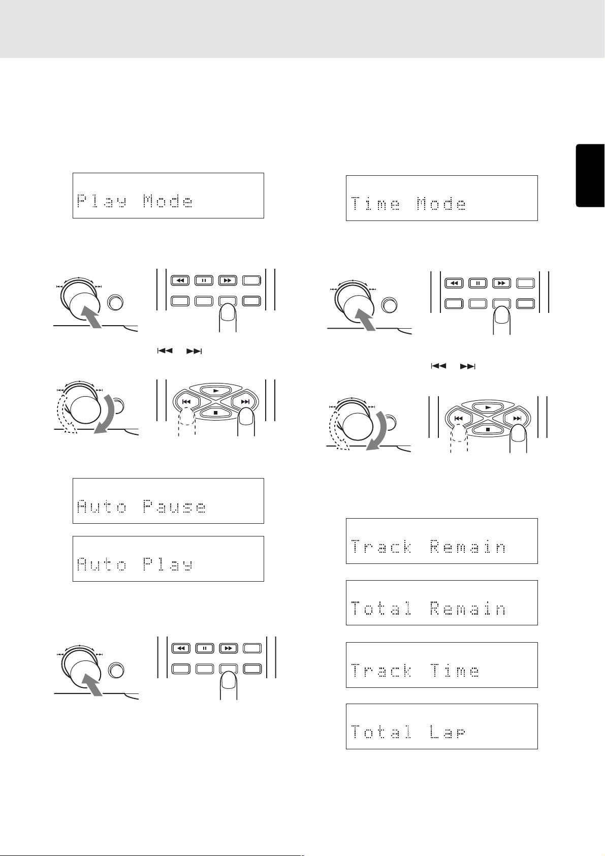
QUICK REPLAY
EASY JOG
SETTING THE PLAY FUNCTIONS
• Play Mode (Auto Pause/Auto Play)
This function makes it possible to select pause or play at the
beginning of a track when performing play or play with a
specific track number designation.
1. Press EASY JOG and then turn it to display “Play Mode”
on the main display.
2. Press EASY JOG (or the ENTER button on the remote
control unit), and select “Play Mode.”
EASY JOG
QUICK REPLAY
TEXT
MENU ENTER
TIME
SCROLL/
RECALL
3. Press EASY JOG (or the or button on the remote
control unit).
EASY JOG
QUICK REPLAY
• Time Mode (Track Remain/Total Remain/
Track Time/Total Lap)
This function selects what kind of time is to be displayed during
play.
1. Press EASY JOG and then turn it to display “Time Mode”
on the main display.
2. Press EASY JOG (or the ENTER button on the remote
control unit), and select “Time Mode.”
TIME
TEXT
MENU ENTER
SCROLL/
RECALL
3. Press EASY JOG (or the or button on the remote
control unit).
EASY JOG
QUICK REPLAY
ENGLISH
“Auto Pause” and “Auto Play” are displayed alternately
on the main display.
4. When EASY JOG (or the ENTER button on the remote
control unit) is pressed, the displayed status is entered.
EASY JOG
QUICK REPLAY
TEXT
MENU ENTER
If, when performing play or play with a specific track
number designation, Auto Pause has been set, pause is
established at the beginning of the track or if Auto Play
has been set, play starts immediately at the beginning of
the track.
TIME
SCROLL/
RECALL
The time mode is selected in succession through a 4-step
cycle: Track Remain → Total Remain → Track Time →
Total Lap → Track Remain.
33
Page 38

QUICK REPLAY
EASY JOG
SETTING THE PLAY FUNCTIONS
4. When EASY JOG (or the ENTER button on the remote
control unit) is pressed, the displayed status is entered.
EASY JOG
QUICK REPLAY
TEXT
MENU ENTER
ENGLISH
At the Track Remain setting, the remaining time of the track
now playing is displayed; at the Total Remain setting, the
remaining time of the disc now playing is displayed; at
the Total Lap setting, the elapsed time of the disc now
playing is displayed; and at the Track Time setting, the
elapsed time of the track now playing is displayed.
Note:
* The time mode cannot be changed if a disc recorded
with MP3 files is used.
• Text Mode (Auto Text/Title Text/Artist Text/
Album Text/Text Off)
This function selects what CD-TEXT or ID3 tag information is
to be displayed.
1. Press EASY JOG and then turn it to display “Text Mode”
on the main display.
TIME
SCROLL/
RECALL
4. When EASY JOG (or the ENTER button on the remote
control unit) is pressed, the displayed status is entered.
2. Press EASY JOG (or the ENTER button on the remote
control unit), and select “Text Mode.”
EASY JOG
QUICK REPLAY
TEXT
MENU ENTER
3. Press EASY JOG (or the or button on the remote
control unit).
EASY JOG
QUICK REPLAY
The text to be displayed is selected in succession through
a 4-step cycle when play is stopped and through a 5-step
cycle during play: Auto Text → Title Text (not displayed
when play is stopped) → Artist Text → Album Text → Text
Off → Auto Text.
No ID3 tag information is displayed when play is stopped
if a disc recorded with MP3 files is used.
34
TIME
SCROLL/
RECALL
TIME
TEXT
MENU ENTER
SCROLL/
RECALL
At the Auto Text setting, the album title is displayed when
play is stopped and the track title is displayed during play,
after which the time display is automatically restored.
At the Title Text setting, the track tile is displayed; at the
Artist Text setting, the album artist is displayed; and at the
Album Text setting, the album title is displayed.
At the Text Off setting, no CD-TEXT or ID3 tag information
is displayed, and the time information is displayed instead.
For details on CD-TEXT, refer to “Concerning CD-TEXT”
(page 38); for details on the ID3 tag, refer to “Concerning
MP3” (page 39).
Page 39

QUICK REPLAY
EASY JOG
QUICK REPLAY
EASY JOG
SETTING THE PLAY FUNCTIONS
• End Warning (ON/OFF)
This function uses an indicator to inform you that the end of
the track now playing is approaching.
1. Press EASY JOG and then turn it to display “End Warning”
on the main display.
2. Press EASY JOG (or the ENTER button on the remote
control unit), and select “End Warning.”
EASY JOG
QUICK REPLAY
TEXT
MENU ENTER
TIME
SCROLL/
RECALL
3. Press EASY JOG (or the or button on the remote
control unit).
EASY JOG
QUICK REPLAY
• Tray Lock (ON/OFF)
This function prevents the tray from opening during play to
safeguard against operational errors.
1. Press EASY JOG and then turn it to display “Tray Lock” on
the main display.
2. Press EASY JOG (or the ENTER button on the remote
control unit), and select “Tray Lock.”
TIME
TEXT
MENU ENTER
SCROLL/
RECALL
3. Press EASY JOG (or the or button on the remote
control unit).
EASY JOG
QUICK REPLAY
ENGLISH
“EndWarn: ON” and “EndWarn: OFF” are displayed
alternately on the main display.
4. When EASY JOG (or the ENTER button on the remote
control unit) is pressed while “EndWarn: ON” is displayed,
the End Warning function is enabled.
EASY JOG
QUICK REPLAY
TEXT
MENU ENTER
When End Warning is set to ON, the end warning indicator
starts flashing 15 seconds before the end of the track now
playing is reached to inform you that the end of the track
is approaching.
Note:
* The end warning indicator does not flash even when the
end warning is set to ON if a disc recorded with MP3
files is used.
TIME
SCROLL/
RECALL
“TrayLock: ON” and “TrayLock: OFF” are displayed
alternately on the main display.
4. When EASY JOG (or the ENTER button on the remote
control unit) is pressed while “TrayLock: ON” is displayed,
the Tray Lock function is enabled.
TIME
TEXT
MENU ENTER
If the Tray Lock is set to ON, the
button on the unit is
disabled while playing and pausing. (The button on the
remote work.) When this is set, “TrayLocked” appears on
the main display to inform you that the tray lock setting is
now ON.
SCROLL/
RECALL
35
Page 40

QUICK REPLAY
EASY JOG
SETTING THE PLAY FUNCTIONS
• Key Lock (ON/OFF)
This function disables the input of the unit to safeguard against
operational errors.
1. Press EASY JOG and then turn it to display “Key Lock” on
ENGLISH
the main display.
2. Press EASY JOG (or the ENTER button on the remote
control unit), and select “Key Lock.”
EASY JOG
QUICK REPLAY
TEXT
MENU ENTER
3. Press EASY JOG (or the or button on the remote
control unit).
EASY JOG
QUICK REPLAY
TIME
SCROLL/
RECALL
• MP3 Load
To play a disc recorded with MP3 files, the unit’s system must
be switched after turning on the power. Once the system is
switched, both music CDs and discs with MP3 files can be
played until the power is turned off.
The MP3 load function enables the system to be switched
manually.
1. Press EASY JOG and then turn it to display “MP3 Load”
on the main display.
2. Press EASY JOG (or the ENTER button on the remote
control unit), and select “MP3 Load.”
TIME
TEXT
MENU ENTER
“MP3 Loading” and a bar indicating the system switching
status appear on the main display.
SCROLL/
RECALL
“KeyLock: ON” and “KeyLock: OFF” are displayed
alternately on the main display.
4. When EASY JOG (or the ENTER button on the remote
control unit) is pressed while “KeyLock: ON” is displayed,
the Key Lock function is enabled.
EASY JOG
QUICK REPLAY
TEXT
MENU ENTER
If the Key Lock is set to ON, all the buttons on the unit
except the Easy Jog button are disabled. (The buttons on
the remote work.) If a button except the Easy jog button
is pressed, “KeyLocked” appears on the main display to
inform you that the key lock setting is ON.
TIME
SCROLL/
RECALL
It takes about 40 seconds for the system to be switched.
The normal display is restored upon completion of system
switching.
36
Page 41

QUICK REPLAY
EASY JOG
SETTING THE PLAY FUNCTIONS
• Auto MP3 Load (ON/OFF)
This function enables the unit’s system to be switched
automatically in order to play discs recorded with MP3 files.
1. Press EASY JOG and then turn it to display “Auto MP3
Load” on the main display.
2. Press EASY JOG (or the ENTER button on the remote
control unit), and select “Auto MP3 Load.”
EASY JOG
QUICK REPLAY
TEXT
MENU ENTER
TIME
SCROLL/
RECALL
3. Press EASY JOG (or the or button on the remote
control unit).
EASY JOG
QUICK REPLAY
“AutoLoad: ON” and “AutoLoad: OFF” are displayed
alternately on the main display.
4. When EASY JOG (or the ENTER button on the remote
control unit) is pressed while “AutoLoad: ON” is displayed,
the auto MP3 load function is enabled.
EASY JOG
QUICK REPLAY
TEXT
MENU ENTER
TIME
SCROLL/
RECALL
• Default
This function enables the data last stored in the memory to
be returned to the initial values. For details, refer to “Last
Memory” (on page 42).
1. Press EASY JOG and then turn it to display “Init Preset”
on the main display.
2. Press EASY JOG (or the ENTER button on the remote
control unit).
TIME
TEXT
MENU ENTER
The data last stored in the memory is returned to the initial
values, and the main display is restored to the normal
display. The table below lists the initial settings.
Play function Initial setting
Pitch Control 0.0%
Single Track Play Single off
Auto Cue Auto Cue off
Repeat Repeat off
AMS Time 10 Sec
Quick Replay Time 10 Sec
Quick Replay Key Quick Replay Key
Timer Play Mode Timer Play off
Play Mode Auto Pause
Time Mode Track Remain
Text Mode Auto
End Warning End Warning off
Tray Lock Tray Lock off
Key Lock Key Lock off
Auto MP3 Loading Auto Loading off
SCROLL/
RECALL
ENGLISH
When auto MP3 load is set to ON, the unit’s system is
switched automatically when the power is turned on. When
it is set to OFF, the unit’s system is switched when a disc
recorded with MP3 files is used.
Alternatively, the unit’s system can be switched manually
using the MP3 Load, which is a play function. (Page 36)
It takes about 40 seconds for the system to be switched.
For details on the displays that appear during system
switching, refer to “MP3 Load” (on page 36).
37
Page 42

9. OTHER FUNCTIONS
Last memory
This function stores the play function settings even after the
power has been turned off.
The settings that can be stored include “AMS Time,” “Quick
Replay Time” and “Timer Play.”
ENGLISH
The data that can be stored in the memory is listed below.
“Pitch”, “Single Track Play Mode”, “Repeat Mode”, “AMS
Time”, “Quick Replay Time”, “Quick Replay Key”, “Timer Play
Mode”, “Play Mode”, “Auto Cue Mode”, “Time Mode”, “Text
Mode”, “End Warning”, “Tray Lock”, “Auto MP3 Load”, “Key
Lock”
CD-TEXT
“CD-TEXT” refers to a new kind of music disc which differs
from a conventional music disc in that album titles, track titles
and other text information are recorded on it. CDs with the
following logos support this function.
CD TEXT
The text information is recorded on those parts which were
not used by conventional music CDs.
This means that discs with recorded CD-TEXT can be played
in the same way as in the past on existing CD players but the
text information can be viewed only when they are played on
a player that supports CD-TEXT.
This player automatically identifies whether a disc supports
CD-TEXT, and it displays the information on the display.
TEXT
• During play
Each time the TEXT button on the remote control unit is
pressed, the information items are displayed in the following
sequence. During play, the information of track now playing
is mainly displayed.
Title of track xx now playing
Album Title
xx Title (title of track xx)
xx Artist (artist of track xx)
xx Songwriter (songwriter of track xx)
xx Composer (composer of track xx)
xx Arranger (arranger of track xx)
Display of player
TRK
TEXT
12 34 56 78 910 1112 1314 1516 1718 1920
This lights when the disc that has been read
is identified as supporting CD-TEXT.
The following items of the text information on CD-TEXT discs
can be displayed in sequence by pressing the TEXT button
on the remote control unit.
CD-TEXT can be displayed also with the Text Mode play
function setting.
For details, refer to page 34.
However, the recorded information differs from one disc to
another so that not all the information given below will
necessarily be displayed. Items not recorded are
automatically omitted and skipped by the player, and only
the existing items are displayed.
TTL
TIME
Time display
• In the stop mode
Each time the TEXT button on the remote control unit is
pressed, the information items are displayed in the following
sequence. When the
displayed, the track concerned starts playing. The maximum
of characters that can be displayed is 64.
-- Title (title of track --)
button is pressed while “-- Title” is
Time display
Album Title
Album Artist
38
Page 43

OTHER FUNCTIONS
CR-R/CD-RW disc play
In addition to conventional music CDs and CD-R (recordable)
discs, this player can also play CD-RW (rewritable) discs. It
also supports the unfinalized discs that cannot be played by
regular CD players.
• Playing unfinalized CD-R/CD-RW discs
CD players normally play only those discs on which the
TOC information (*) has been recorded. This means that
in order for a CD player to play a CD-R/CD-RW disc with
music recordings, the disc had to be “finalized” by writing
the TOC information onto it.
Discs for which this finalizing job has not been done are
called unfinalized discs, and this player is designed to
support the play of these unfinalized discs as well.
Consequently, even CD-R/CD-RW discs on which more
material is to be recorded can be enjoyed without further
ado using this player.
* “TOC” stands for the table of contents which contains
the total number of tracks, the total play time and other
such information on the disc. This information has been
recorded on the inner circumference area of the disc.
• Precautions for unfinalized CD-R/CD-RW
discs
Take care not to scratch or dirty the area near the innermost
circumference of unfinalized CD-R/CD-RW discs.
Scratches, dirt or other abnormalities in this area may make
it impossible for the disc to be read.
On unfinalized CD-R/CD-RW discs recorded using a CD
recorder for audio applications, provisional TOC information
is recorded in the PMA area (*) which is further inside from
the TOC information area. This player supports unfinalized
discs by reading the information in the PMA area, but
because this area is extremely narrow, any scratches, dirt
or other abnormalities here may make it impossible for discs
to be read.
On some discs, this area may be very difficult to read. In
cases like this, use the disc after using a CD recorder to
do the finalizing. It is recommended that the finalizing be
done before scratches or dirt makes it hard for the discs to
be read.
* “PMA” stands for program memory area, and it refers to
the area where the provisional contents information such
as the number of tracks and play times recorded on the
CD-R/CD-RW discs is recorded. Discs cannot be played
by this player unless the PMA has been recorded properly.
MP3
This player can play CD-R/CD-RW discs as well as discs
available on the market recorded using MP3 files (*).
The ID3 tag (*) is supported by this player. The album title,
track title and name of the artist can be displayed for the
track (file) on which the ID3 tag information has been recorded.
* “MP3” refers to music data which has been compressed by
a file format known as “MPEG-1 Audio Layer 3.” Files with
the “.mp3” or “.MP3” extension are called MP3 files.
* “ID3 tag” refers to a format which adds the album title, track
titles, names of the artists and other text information to the
MP3 files.
• MP3 file playback
Playing albums in sequence
1. As with a music CD, place the disc recorded using the
MP3 files on the disc tray, and retract the disc tray.
2. Press the button on the player or the button on the
remote control unit.
Play now starts in sequence from the first album (on a
folder by folder basis (*)). (See next section.)
With a disc recorded with MP3 files, it takes about 40
∗
seconds after the player’s power has been turned on
for the player’s system to be switched before initial play.
Selecting and playing albums (folders)
Select the desired album (on a folder by folder basis (*)) using
the or button on the player or remote control unit.
Play now starts in sequence from the selected album. The
album number appears on the display.
(AL xxx)
• Displaying the ID3 tag information
The following display appears when the TEXT button on the
remote control unit is pressed while playing an MP3 file disc
on which the ID3 tag information has been recorded.
During play
Title of track xx now playing
(The text display is automatically
switched to the time display.)
Album Title
xx Title (title of track xx)
ENGLISH
This player supports the discs which have been recorded
∗
by any recorder that complies with the “Orange Book” of
CD-R/CD-RW standards.
The player can play only those discs recorded in the music
∗
format (CD-DA) or using MP3 files.
If there is not much recording time, it may be difficult for
∗
the data to be read out, and it may cause error.
When the player is to play a CD-RW disc or unfinalized
∗
CD-R/CD-RW disc, it automatically recognizes the type of
disc, and changes some of its internal settings to suit the
disc concerned. For this reason, the disc reading process
will take a little longer compared with regular music CDs
or CD-R discs.
xx Artist (Artist of track xx)
Time display
Those items among the display information which were not
∗
recorded are skipped, and only the recorded items are
displayed.
During stop
The ID3 tag information is not displayed during stop.2
39
Page 44

OTHER FUNCTIONS
aaaa05.mp3
aaaa06.mp3
bbbb07.mp3
bbbb08.mp3
cccc09.mp3
cccc10.mp3
aaaa04.mp3
aaaa03.mp3
yyyy.jpg
zzzz.doc
dddd11.mp3
dddd12.mp3
AAAA01.mp3
BBBB02.mp3
eeee13.mp3
eeee14.mp3
gggg16.mp3
gggg17.mp3
wwww.wav
xxxx.wav
ffff15.mp3
Album 02
Album 04
Album 05
Album 03
Album 06
Album 07
Album 10
Album 01
Album 08
Root
Album 09
(E)
• Precautions for discs recorded using MP3
files
The format of the files played have the “.mp3” or “.MP3”
∗
extension. Files with any other extension cannot be played.
The Joliet file system, an extension to the ISO9660 file
∗
ENGLISH
format, is supported as the write format. Both mode 1 (CDROM) and mode 2 (CD-ROM XA) are supported. MP3 file
discs recorded using packet writing cannot be played.
The supported MP3 file sampling frequency is 16 kHz – 48
∗
kHz and the bit rate is 32 kbps – 320 kbps.
44.1kHz, 128kbps are recommended for the unit.
The maximum number of characters in the ID3 tag
∗
information that can be displayed by this player is 32.
Characters other than alphanumerics will not be displayed
properly. Japanese characters cannot be displayed.
Digital signals are not output from the player while playing
∗
discs recorded using MP3 files.
It may not be possible for CD-R/CD-RW discs on which
∗
MP3 files were recorded to be played properly depending
on the environment of the personal computer used to record
the files, the writing software program and the CD-R/CDRW discs concerned. Check the external components
used.
MP3 files on mixed CDs or enhanced CDs containing a
∗
mixture of the CD-DA format for music purposes and MP3
files cannot be played. Only the CD-DA format for music
purposes will be played.
This player also supports discs created by multisessions.
∗
It is recommended that the maximum number of sessions
∗
on a CD-R or CD-RW disc be 10, the maximum number of
albums for all sessions be 20 and the maximum number of
files be 200.
• Example of play sequence
Diagram showing sequence as displayed by Win-
dows Explorer
CD-ROM drive
Play up to 8 hierarchical levels possible
Display that appears when the disc shown above is
inserted (in the stop mode)
Total number of tracks
• Functions not supported by MP3 play
The following functions are not supported when the player
is to play discs recorded with MP3 files.
- A-B repeat
- Program play
- Delete program play
- Index skip
- End monitor
- Manual cue
- Auto cue
- Time mode changes
- End warning
• Concerning random play
Random play proceeds on an album by album (folder by
folder) basis. When all the tracks of the album currently playing
have been played, play moves on to the next album in the
sequence.
During random play, the 1-track repeat and A-B repeat
functions cannot be used.
40
TTL
TRK
12 4 56 7 910
Album that contains MP3 files
Total number of MP3 albums
MP3
• The dotted line with arrow ( ) indicates the sequence
in which the MP3 albums and tracks are played.
• Album 01 to album 10
In the example shown in the figure, this CD-ROM has 10
albums (folders) but albums 03 and 08 are not MP3 files
and so cannot be played.
• AAAA01.mp3 to gggg17.mp3
In the example shown in the figure, this CD-ROM has 17
tracks starting with track “01” and ending with track “17.”
• Only those files with the “.mp3” extension are played; all
other files with the .wav, .jpg, .doc and other extensions
are skipped.
• Album 01 is allocated even when there are no files in the
root.
• The sequence may differ from the one that appears on the
personal computer. It may also differ depending on the
writing software program.
Page 45

OTHER FUNCTIONS
How to use the CONTROL I/O
(control input/output) connector
This input/output connector (D-Sub 25-pin female) is used
for remote control.
Contact circuits (switches, etc.) can be connected to each of
the input and output pins.
In addition, by connecting displays, etc. to the output pins,
statuses can be monitored from a distance.
Notes:
* Use the tally power supply at pin 12 at a total load current
of less than 80 mA.
* Use a D-Sub 25-pin male (4-40UNC for the screw part)
connector as the compatible connector.
* Refer to the example of the connections shown in the
figure on the right to connect a cable to the CONTROL I/
O connector.
Example of CONTROL I/O (input/output) connections
When using pin 4 (FADER NORMAL)
171820192122232425
141516
101112
13
CUE
2
14
23
END
2
15
NEXT
7
14
20
2
14
14
PLAY
14
(NORMAL)
FR
2
1
25
4
9
14
3456789
PAUSE
2
14
24
FADERFADER
2
17
FF
PREVIOUS
22
14
When using pin 16 (FADER INVERT)
171820192122232425
141516
101112
2
1
3456789
PLAY
2
14
25
(INVERT)
14
16
FR
9
14
PAUSE
2
14
24
FADERFADER
2
17
FF
PREVIOUS
14
22
14
13
CUE
2
14
23
END
2
15
NEXT
7
14
20
ENGLISH
Pin no. Signal
1FG -
2 TALLY POWER SUPPLY -
3 QUICK REPLAY I
4 FADER NORMAL I
5 PITCH ON OFF I
6 PITCH+ I
7 PREVIOUS I
8 INDEX- I
9FR I
10 STOP I
11 CUE TALLY O
12 PAUSE TALLY O
13 PLAY TALLY O
14 TALLY COMMON -
15 END TALLY O
16 FADER INVERT I
17 FADER TALLY O
18 PITCH- I
19 N.C. -
20 NEXT I
21 INDEX+ I
22 FF I
23 CUE I
24 PAUSE I
25 PLAY I
Table showing CONTROL I/O signal layout
I/O
Function Port specification
Frame GND
Tally power supply
Identical to QUICK REPLAY button
Refer to page 42 (fader start)
Identical to PITCH RESET button on remote control unit
Identical to PITCH+ button on remote control unit
Identical to button
Identical to INDEX- button on remote control unit
Identical to button
Identical to button
ON when CUE point is set
ON during pause
ON during play
Tally GND
Identical to END WARNING indicator
Refer to page 42 (fader start)
ON during fader play
Identical to PITCH- button on remote control unit
Not used
Identical to button
Identical to INDEX+ button on remote control unit
Identical to button
Identical to button
Identical to button
Identical to button
-
+5V, Imax=80mA
CMOS
CMOS
CMOS
CMOS
CMOS
CMOS
CMOS
CMOS
Ii<20mA
Ii<20mA
Ii<20mA
-
Ii<20mA
CMOS
Ii<20mA
CMOS
-
CMOS
CMOS
CMOS
CMOS
CMOS
CMOS
41
Page 46

OTHER FUNCTIONS
Fader start
When the fader start switch incorporated into a component
such as a mixer board or mixing console or an external switch
is connected to the fader start jack, play/pause control can
be exercised by opening and closing the switch.
ENGLISH
When using CONTROL I/O connector pins 4 (FADER
NORMAL) and 14 (TALLY COMMON)
BALANCED
R L
OUTPUT LEVEL
L
R
DIGITAL OUT
OPT.COAX.
ANALOG OUT
Fader start polarity
Play Closed
Pause Open
When using CONTROL I/O connector pins 16 (FADER
INVERT) and 14 (TALLY COMMON)
BALANCED
R L
OUTPUT LEVEL
L
R
DIGITAL OUT
OPT.COAX.
ANALOG OUT
Fader start polarity
Play Open
Pause Closed
IN
OUT
EXTERNAL INTERNAL
REMOTE CONTROL
IN
OUT
EXTERNAL INTERNAL
REMOTE CONTROL
RS232CCONTROL I/O
DIGITAL OUT
(
)
SPDIF
CONNECTION
1 GND
(+)
2 HOT
231
(-)
3 COLD
Fader (NORMAL)
switch
RS232CCONTROL I/O
DIGITAL OUT
(
)
SPDIF
CONNECTION
1 GND
(+)
2 HOT
231
(-)
3 COLD
Fader (INVERT)
switch
Remote control codes
This unit receives the codes listed in the table below from the
infrared remote sensor on the front panel and the remote
control connector on the rear panel, and it performs the
operations that correspond to those codes.
Remote control codes (RC5)
Command CODE
02000
12001
22002
32003
42004
52005
62006
72007
82008
92009
Time 2011
Recall/Scroll 2015
Random 2028
Repeat 2029
Next 2032
Previous 2033
Index + 2034
Index - 2035
Pitch Reset 2037
Pitch + 2038
Pitch - 2039
Program 2041
AMS 2043
Open/Close 2045
Pause 2048
Cancel 2049
Search Rev 2050
Search FF 2052
Play 2053
Stop 2054
A-B 2059
Display (Dimmer) 2071
Menu 2082
Enter 2087
Text 2088
Edit 20104
Quick Replay 205304
42
Page 47

OTHER FUNCTIONS
How to use the RS-232C connector
This input/output connector (D-Sub 9-pin female) is used for
RS-232C external control.
A straight cable available on the market can be connected to
this connector to exercise external control and send status
information.
• Connector pin assignment
1NC
69
51
• RS232C Connection
PMD325 Typical HOST
Transmit Data
Receive Data
Ground
2
3
5
2TX
3RX
4NC
5 GND
6NC
7NC
8NC
9NC
Rx Data
2
Tx Data
3
Ground
5
Example: Reception Time Command (code 2011)
2 0 1 1 CR
0x32 0x30 0x31 0x31 0x0d
When transmitting commands consecutively, put more than
100ms blank between commands.
Received command data
Command Code Command Code
0 2000 Pitch Down Start 2039
1 2001 Pitch Down Stop 203901
2 2002 Program 2041
3 2003 AMS 2043
4 2004 Open/Close 2045
5 2005 Pause 2048
6 2006 Cancel 2049
7 2007 Fast Backward Start 2050
8 2008 Fast Backward Stop 205001
9 2009 Fast Forward Start 2052
Time 2011 Fast Forward Stop 205201
Recall/Scroll 2015 Play 2053
Random 2028 Stop 2054
Repeat 2029 A-B 2059
Next 2032 Display (Dimmer) 2071
Previous 2033 Menu 2082
Index + 2034 Enter 2087
Index - 2035 Text 2088
Pitch Reset 2037 Quick Replay 205304
Pitch Up Start 2038 Cue 205910
Pitch Up Stop 203801
ENGLISH
D-Sub 9 Pin
(male)
D-Sub 9 Pin
(female)
The wiring requirements for a 9 pin to 9 pin serial connection,
are a male to female straight cable.
• RS-232C physical specifications
Cable Straight cable
Baud rate 9600 bps
Data bits 8 bits
Parity bit None
Stop bit 1 bit
Flow control None
• Command reception
The command packets have a data length of 5, 6 or 7 bytes.
ASCII codes from 0x00 to 0x7f are used to receive serial data.
At the transmission end, therefore, take steps to convert the
ASCII codes into HEX data to set the data in the data packets.
CR (0x0d) is added as the data packet delimiter.
• Status transmission
The status packets have a fixed data length of 4 bytes.
ASCII codes from 0x00 to 0x7f are used to transmit serial
data. For this reason, the ASCII codes are converted into
HEX data before the data is set in the data packets and
transmitted. CR (0x0d) is added as the data packet delimiter.
Example 1: Transmission Power On (code PWON)
P W O N CR
0x50 0x57 0x4f 0x4e 0x0d
Transmitted status data
Status Code Description
Power On PWON Transmitted when the power is turned on.
Tray Open TROP Transmitted upon completion of tray open.
Tray Close TRCL Transmitted upon completion of tray close.
TOC Error TOCE
TOC Reading TOCR Transmitted when TOC read is started.
No Disc NODI Transmitted when “No disc” is detected.
Stop STOP Transmitted when the disc has stopped.
Play Pxxx
Pause Axxx
Fast Forward FFON Transmitted when Fast Forward is started.
Fast Backward RWON Transmitted when Fast Backward is started.
Repeat Off RPOF Transmitted when Repeat Off is set.
Repeat All RPAL Transmitted when Repeat All is set.
Repeat One RPON Transmitted when Repeat One is set.
Repeat A RPA- Transmitted when Repeat A is set.
Repeat AB RPAB Transmitted when Repeat A-B is set.
End Warning ENDW Transmitted when End Warning is started.
Transmitted when a TOC read error has occurred.
Transmitted along with the track number (xxx)
when play is started; also transmitted when
the track number is changed during play.
Transmitted along with the track number (xxx)
when the pause status is established.
43
Page 48

OTHER FUNCTIONS
Installing the rack-mounting kit
Follow the steps below to install the rack-mounting kit on the
unit.
1. Remove the four screws on the side panels of the unit.
ENGLISH
Screw
3. Align the front panel with the boss screws provided in the
side panels of the rack-mounting kit, and fit it in place.
After having attached the front panel, secure it by
tightening up the four box nuts as shown in the figure
below.
Front panel of
rack-mounting kit
Box nut
Screw
2. Using the four screws which were removed in step 1, attach
the two side panels of the rack-mounting kit as shown in
the figure below.
Screw
Side panel (R) of
rack-mounting kit
Side panel (L) of
rack-mounting kit
Screw
Boss screw
4. The figure below shows how the rack-mounting kit looks
when it has been installed.
Tips
* When attaching the two side panels of the rack-mounting kit
in step
2, first loosely tighten the four screws, and then while
making adjustments so that the front panel of the rackmounting kit and front panel of the main unit are level, tighten
up these four screws securely.
* If necessary, remove the feet on the unit’s bottom panel.
44
Page 49
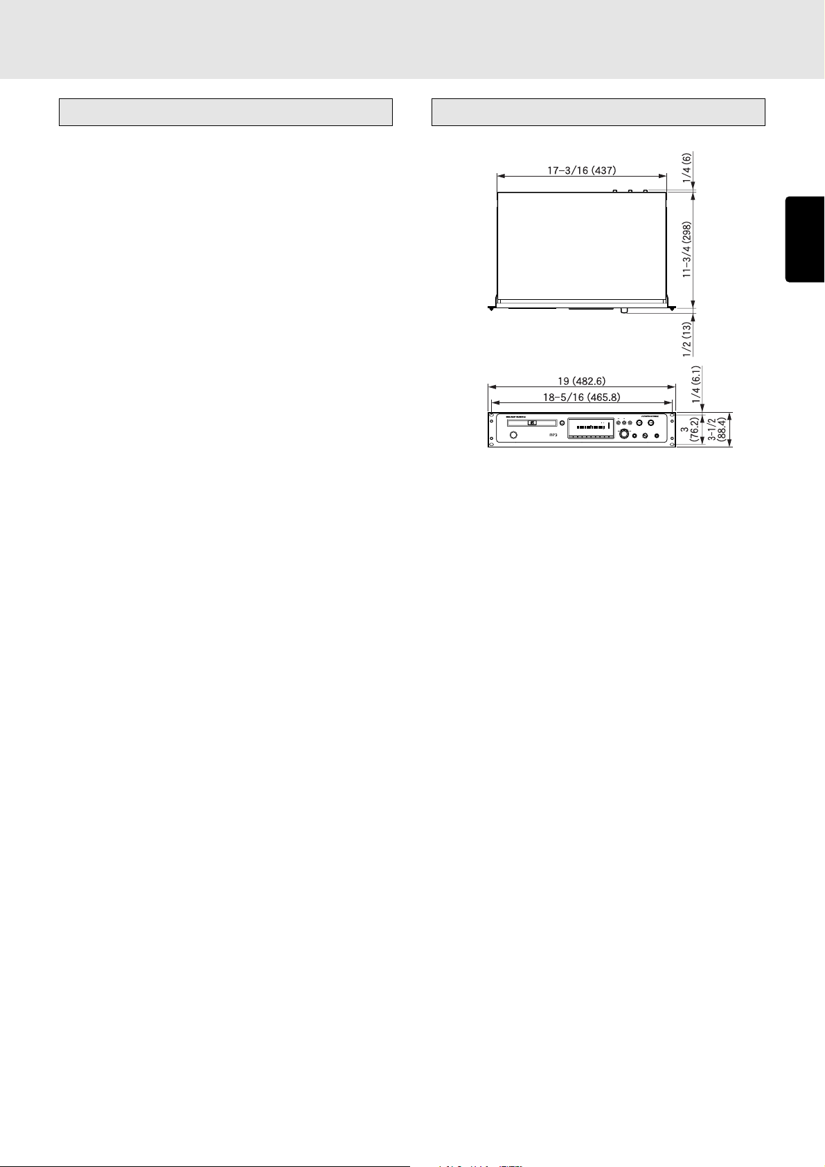
10. SPECIFICATIONS AND DIMENSIONS
Specifications
General specifications
System ....................................... Compact disc digital audio
Number of channels............................................................ 2
Compatible discs ............. CD, CD-R, CD-RW (12 cm, 8 cm)
Audio characteristics
Channels ............................................................................. 2
Frequency response ......................20 Hz to 20 kHz ± 0.5 dB
Dynamic range..............................................100 dB or more
Signal-to-noise ratio ................................ Better than 110 dB
Channel separation .......................... 100 dB or more (1 kHz)
Total harmonic distortion ............................. 0.0025% (1 kHz)
Wow & flutter ................................... Quartz crystal accuracy
Error correction system ..................... Cross-interleave Reed-
Solomon code (CIRC)
Analog output
Analog unbalanced output (RCA) ............ 2V RMS stereo
Analog balanced output (XLR).......... +16 dBu/600 ohms
(factory setting)
Variable range ................................... -11 to +21 dBu
Digital output
Coaxial digital output ........................... 0.5Vp-p/75 ohms
Optical digital output .......................................... -19 dBm
Digital balanced output ...................... 3.5Vp-p/110 ohms
Pitch control ............................ ± 12.0% in 0.1 dB increments
Dimensions (unit: inch (mm))
CD PLAYER PMD325
OPEN/CLOSE
TIMER
RNDM
PROG A — B
RPT1S.PLAY
DISC
TTL
TRK INDX
TTL
TIME
END
WARNING
MP3
TEXT
POWER ON/OFF
1234 56 78910111213141516 17181920
1
23456789
PLAY/PAUSE
CUESTOP
—+
ALBUM
EASY JOG
0
PHONESLEVELQUICK REPLAY
+
-
ENGLISH
Remote control
Infrared remote control input.................................. IR sensor
Remote control input ....... RCA (INT/EXT switching enabled)
Control input/output ............................. D-Sub 25-pin female
RS-232C ................................................. D-Sub 9-pin female
Optical readout system
Laser ................................................ AlGaAs semiconductor
Wavelength ............................................................... 780 nm
Signal system
Sampling frequency ................................................ 44.1 kHz
Quantization ..........................................16-bit linear/channel
Power supply
U version ..................................................... AC 120 V, 60 Hz
Power consumption ...................................................... 12 W
Cabinet, etc.
Maximum dimensions
Including rack-mounting kit
................................. 19 (W) x 3-1/2 (H) x 12-7/16 (D) in.
(482.6 (W) x 88.4 (H) x 316.5 (D) mm)
Main unit only ... 17-5/16 (W) x 3-9/16 (H) x 12-1/2 (D) in.
(440(W) x 90(H) x 317 (D) mm)
Weight
Including rack-mounting kit...................... 11 lbs (5.0 kg)
Main unit only ........................................ 9.46 lbs (4.3 kg)
Allowable operating temperature....................... +5 to +35°C
Allowable operating humidity.... 5 to 90% (no condensation)
This player’s specifications and exterior are subject to change
without notice for improvements.
45
Page 50

11. TROUBLESHOOTING
If you think that something is wrong with your player, first check
the points listed below. Incorrect operations can sometimes
be taken for trouble and malfunctions. If the trouble persists
even after the following points have been checked, consult
your dealer or nearest Marantz sales office or service center.
ENGLISH
Disc fails to turn.
• Has the power cord been connected properly?
• Has the player’s power been turned on?
• Has the disc been placed in the proper position?
• Is the disc upside down? (Is the disc’s label surface facing
up?)
• Is the disc dirty?
• Is the disc scratched?
• Is the disc warped?
Disc turns but no sound is heard.
• Have the amplifier and speakers been connected properly?
• Has the amplifier’s power been turned on?
• Has the amplifier’s function or selector switch been set to
“CD” or “AUX” (or to whichever connectors the player has
been connected)?
• Is the amplifier’s volume at its lowest setting?
Disc starts turning but then stops at some point.
• Is the disc dirty?
• Is the disc scratched?
• Is the disc warped?
• Is the disc being played a music CD? CD-ROMs (except
their MP3 files) for personal computers, etc. cannot be
played.
No remote control operations.
• Is the transmitter of the remote control unit (RC7300CD)
pointed at the remote sensor of the player? Is there anything
between the player and remote control unit which is
blocking the signals?
• Have the batteries of the remote control unit (RC7300CD)
run down?
• Is a strong light shining on the remote sensor of the player?
• Is the REMOTE CONTROL switch on the rear panel set to
the EXTERNAL position? (Set it to the INTERNAL position
if the player is to be used on its own.)
CD-R/CD-RW discs cannot be played.
• Has the disc been placed upside down on the disc tray?
• Is the recorded information in a format (CD-DA or MP3)
used for music applications?
46
Page 51

Limited Warranty
Your Marantz Professional product is warranted against manufacturer
defect for period of one year parts and labor.
Except as specified below this warranty covers defects in material
and workmanship. The following are not covered under warranty.
1. a) Damage, deterioration, malfunction or failure to meet
performance specification resulting from:
b) Accidents, acts of nature, misuse, abuse, neglect or
unauthorized product modification.
c) Improper installation, removal or maintenance, or failure to follow
supplied instruction.
d) Repair or attempted repair by a non Marantz authorized agent.
e) Any shipment of the product (claims must be presented to the
carrier).
f) Any cause other than a defect in manufacturing.
2. Cleaning, check-ups with no fault found, or changes incurred for
installation, removal or reinstallation of the product.
3. Any serialized product on which the serial number has been
defaced, modified or removed.
4. Batteries and battery chargers.
5. Accessories, including but not limited to, cables, mounting hardware
and brackets, cleaning accessories, power cords and adaptors,
and carry cases.
6. Product purchased outside the United States, its possessions or
territories.
How You Can Get Service
1. If your unit needs service, contact our service referral at the
appropriate telephone number indicated below. We will advise you
of the name and location of one or more warranty authorized service
centers from which service may be obtained. Please do not return
your unit directly to us.
2. You must pay any shipping charges if it is necessary to ship the
product for service. If the necessary repairs are covered by the
warranty, we will pay the return shipping charges to your location
anywhere in the United States or its territories.
3. Whenever warranty service is required, you must present the
original dated sales receipt or other proof of date purchased.
Limitation of Implied Warranties
All implied warranties, including warranties or merchantability and
fitness for a particular purpose, are limited in duration to the length or
this warranty.
Exclusion of Damages
Liability for any defective product is limited to repair or replacement of
the product at manufacturer’s option. Manufacturer shall not be liable
for damage to other products caused by any defects in Marantz
products, damages based upon inconvenience or loss of use of the
product, or any other damages, whether incidental, consequential, or
otherwise.
Non-Transferable Warranty
This warranty may be enforced only by the original purchaser.
What We Will Pay For
We will pay for all labor and material expense for items covered by
the warranty.
Some states do not allow limitations on how long an implied warranty
lasts and/or do not allow the exclusion or limitation of incidental or
consequential damages, so the above limitations and exclusions may
not apply to you.
How State Law Relates to the Warranty
This warranty gives you specific legal rights, and you may have other
rights which may vary from state to state.
Marantz Professional Service Number:
Marantz Professional Factory Service (630) 820-4800
This warranty is enforceable only in the United States and its
possessions and territories.
Page 52

R
is a registered trademark.
2002/10 MITs 09AK851250Printed in Japan
 Loading...