


INSTALLATION INSTRUCTIONS
HOOD MODELS – LOH36, LOH48 & LOH60
IMPORTANT SAFETY INSTRUCTIONS
PLEASE READ ENTIRE INSTRUCTION BEFORE PROCEEDING.
INSTALLATIONS MUST COMPLY WITH ALL LOCAL CODES.
IMPORTANT: Save these Instructions for the Local Electrical Inspector's use.
INSTALLER: Please leave these Installation Instructions with this unit for owner.
OWNER: Please retain these Instructions for future reference
WARNING - TO REDUCE THE RISK OF FIRE, ELECTRICAL SHOCK, OR INJURY TO PERSONS, HOODS SHOULD BE INSTALLED WITH VENTILATORS APPROVED FOR USE WITH THE HOOD. SEE TABLE – 1 ON THIS PAGE FOR APPROVED VENTILATORS.
WARNING - TO REDUCE THE RISK OF FIRE, ELECTRIC SHOCK, OR INJURY TO PERSONS, OBSERVE THE FOLLOWING:
A.Installation work and Electrical Wiring Must Be Done By Qualified Person(s) In
Accordance With All Applicable Codes
& Standards. Including Fire-Rated
Construction. “WARNING” To Reduce
The Risk Of Fire, Use Only Metal Duct
Work.
B.Sufficient air is needed for proper combustion and exhausting of gases
through the flue (chimney) of fuel burning equipment to prevent backdrafting. Follow the heating equipment manufactures guideline and safety standard such as those published by the National Fire Protection Association (NFPA) and the American Society for Heating, Refrigeration and Air Conditioning Engineers (ASHRAE), and the local code authorities.
C.When cutting or drilling into wall or ceiling, do not damage electrical wiring and other hidden utilities.
D.Ducted fans must always be vented to the outdoors.
E.Before Servicing or Cleaning Unit, Switch Power off At Service Panel And Lock Service Disconnecting Means to Prevent Power From Being Switched On Accidentally. When The Service Disconnecting Means Cannot be Locked, securely Fasten A Prominent Warning Device, Such As A Tag, To The Service Panel
CAUTION - TO REDUCE THE RISK OF FIRE AND TO PROPERLY EXHAUST AIR, BE SURE TO DUCT AIR OUTSIDE FOR DUCTED FANS – DO NOT VENT EXHAUST AIR INTO SPACE WITHIN WALLS OR CEILING OR INTO ATTICS, CRAWL SPACES OR GARAGES.
Read this instruction completely before starting installation. Planning the complete installation before starting any work is highly recommended. This includes all aspects of the installation including hood location, ducting, electrical requirements, and adequacy of mounting surfaces.
 TABLE - 1
Model LOHI = Internal ventilator  Model LOHE = Remote ventilator
This hood series has been designed to be used with the ventilators shown in Table – 1. Before cutting into cabinets, it is necessary to confirm that the correct ventilator is being used. Your dealer should have reviewed your needs prior to your purchase. Be sure you have the correct ventilation system.
CAUTION: To Reduce The Risk Of Fire And Electrical Shock, Install This Rangehood Only With Blowers Manufactured By Lynx Professional Grills.
DUCTING: Use a minimum 10" round duct for LOHI and LOHE installations. See Page – 3. A standard starting transition (33895) is included with the Hood.
 SAFTY WARNING:
Turn off power circuit at the service entrance and lockout panel before wiring the range hood.
NOTE: Unit must be vented
to the outside of the building.
Page 1 of 8 P/N 11857.00 Rev A
BEFORE STARTING INSTALLATION, YOU MUST IDENTIFY THE VENTILATOR MODEL BEING USED AND IF A TOP OR REAR EXHAUST IS TO BE USED.
Prepare cabinet and/or wall for mounting either top (Fig - 1) or rear (Fig 6 & 7) exhaust. Use furring strips to level cabinet mounting surface with any cabinet trims.
For knock out removal see Fig- B
|
Remove |
|
See |
Ventilator Model |
Knock out # |
Transition # |
Fig |
LOHI Top Exhaust |
1 |
33895 |
1,2,3 |
LOHE Top Exhaust |
1 |
33895 |
1,2,3 |
LOHI Rear Exhaust |
2 |
33895 |
4,5,6,7 |
LOHE Rear Exhaust |
2 |
33895 |
5,6,7 |
Break the metal webs by placing a screwdriver at one corner of the plate and hitting screwdriver sharply with a hammer. After breaking a second web the plate can be flexed to break other webs.
Wear eye protection when using tools.
Caution: When knock outs are removed the edges will be sharp! Sharp Edges should be Filed or Covered with Metal Tape.
Attach and secure the transition to the hood with #6x3/8 sheet metal screws and tape all joints prior to installing the hood. Attach hood to cabinet using #10 wood screws. Holes are located in the back panel and top panel of the hood for mounting. Use a minimum of four #10x3/4 wood screws to mount the hood. Longer screws are required if wall board or
other nonstructural surfaces are used between the hood and main mounting surface which should be a minimum of 3/4”
thick. When using rear holes for additional mounting use appropriate anchors if not engaging the wood structure. HINT: If you find vibration noise is present because of cabinet structure use additional screws, in holes available, to make the mounting more ridged.
Connect 120 volt, 60 Hz power through the conduit hole in top of hood, connecting to pigtail in hood junction box, white to white, black to black and connect green ground wire to the power supply ground wire per local codes. See Fig – A.
NOTE: Recommended height over BBQ Grills = 36 inches.
Hood is recommended for use over domestic gas or electric appliances. Not recommended for use over solid fuel fired appliances.
After installing the hood, install the internal blower (Top Exhaust See Fig 2; Rear Exhaust See Fig - 4) unit by positioning the blower onto bracket-A, notched blower bracket will center blower. Rotate into position against hood and secure Bracket – B to Hood with #8 sheet metal screws. If the remote ventilator is used see related instructions. The
LOHE ventilator will require revision of some wiring in the hood receptacle box - See LOHE instructions.
NOTE: LOHE requires a dedicated 20 AMP Power Supply. All other ventilators require a dedicated 15 AMP Power Supply
CAUTION: The hood is of sufficient weight that two installers are recommended to prevent injury or damage to the hood in handling.
Turn the power on at the service entrance and check the operation of the controls.
NOTE: be sure that all dampers are operating properly and are free to open.
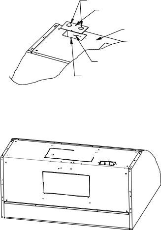
RECEPTACLE BOX COVER
Knock Outs
Cover
Hood Top
Hood Wiring Access
Mounting Screw
Remove Appropriate Knock Outs and Connect Wiring According to Hood and Blower Installation Instructions. CAUTION: Always Install Receptacle Box Cover.
Fig – A
1 


2
Fig - B
Page 2 of 8 P/N 11857.00 Rev A

FIG-1 |
HOOD MODELS LOHI |
|
TOP EXHAUST |
||
|
||
|
Bottom View Of Cabinet - |
|
|
Internal Or Remote Blowers |
Hood Width |
Dim "A" |
36" |
10-3/8 |
48" |
14-3/8 |
60" |
20-3/8 |
|
|
|
|
C |
|
|
|
|
|
5" |
"A" |
L |
|
12" |
|
|
|
10-1/4" |
|
||||
|
|
4" |
7-1/8" |
7-1/8" |
|
|
|
|
|
|
|
|
|
|
|
|
|
Wiring Access |
3/4" |
|
Back Wall |
|
|
|
|
Add Furring Strips To Provide An Even |
|
|
|||
|
|
Bottom Surface For The Hood Mounting |
|
|
|||
FIG-2 |
Secure Transition To Hood Using #6 X 3/8" |
|
Vertical Discharge |
FIG - 3 |
|||
Sheet Metal Screws. Tape All Joint & Seams |
|
|
|
|
|||
Remove Knock Out # 1 |
|
|
|
|
10" Duct to |
|
|
Air Flow |
Use # 33895 |
|
|
Discharge W/Roof Cap |
|
||
|
|
|
|
|
|
|
|
|
|
|
Transition |
12" |
|
Transition # 33895 |
|
|
|
|
To 10" Duct |
|
|
|
|
|
LOHI |
|
|
|
|
18" |
|
|
|
|
|
|
|
|
|
|
|
|
|
3" |
|
|
|
|
Rotate |
|
|
All |
Hoods |
30" |
|
|
Into |
|
|
|
|||
|
|
|
|
|
|
||
|
Position |
|
|
|
|
|
|
|
& Secure |
|
|
|
The 10" Discharge With Transition |
|
|
|
With 2 Screws |
|
|
Will Be On The Center Line Of Hood Width |
|||
|
|
|
|
|
And On Center Line of 12" Dimension. |
|
|
FIG - 4 |
|
|
HOOD MODELS LOHI |
|
|
|
|
|
|
|
|
|
|
|
|
|
|
|
|
|
|
|
|
|
|
|
|
|
|
|
|
|
|
|
|
|
|
|
|
Hood Width |
Dim "A" |
|||||||||
|
|
|
|
|
|
|
|
|
|
|
|
|
|
|
|
|
|
|
|
|
|
|
|
|
|
|
|
|
|
|
|
|
|
|
|
|
|
36" |
10-3/8 |
|||||||||||
|
|
|
|
|
|
|
|
|
|
|
REAR EXHAUST |
|
|
|
|
|
|
|
|
|
|
|
|
|
|
|
|
|
|
|
|
|
|
|
|
|
|
|
|
|
|
|
|
|||||||
Remove Knock Out # 2 |
|
|
|
|
|
Bottom View Of Cabinet |
|
|
|
|
|
|
48" |
14-3/8 |
||||||||||||||||||||||||||||||||||||
|
|
|
|
|
|
|
|
|
||||||||||||||||||||||||||||||||||||||||||
|
|
FIG - 6 |
||||||||||||||||||||||||||||||||||||||||||||||||
LOHI |
|
|
|
|
|
|
|
|
|
|
|
|
Internal Or Remote Blowers |
|
|
|
|
|
|
60" |
20-3/8 |
|||||||||||||||||||||||||||||
|
|
|
|
|
|
|
|
|
|
|
|
|
|
|
|
|
|
|
|
|
|
|
|
|
|
|
|
|
|
|
|
|
|
|
|
|
|
|
|
|
|
|
|
|
|
|
|
|
|
|
|
|
|
|
|
|
|
|
|
|
|
|
|
|
|
|
|
|
|
|
|
|
|
|
|
|
|
|
|
|
|
|
|
|
|
|
|
|
|
|
|
|
|
|
|
|
|
|
|
|
|
|
|
|
|
|
|
|
|
|
|
|
|
|
|
|
|
|
|
|
|
|
|
|
|
|
|
|
|
|
|
|
|
|
|
|
|
|
|
|
|
|
|
|
|
|
|
|
|
|
|
|
|
A |
|
|
|
|
|
|
|
C |
|
|
|
|
|
L Top Of Hood |
12" |
|
Rotate |
|
5" |
"A" |
||
B |
|
||||
4" |
|
|
|||
Into |
|
|
|||
|
|
|
|
||
Position |
|
Wiring Access 3/4" |
Back Wall |
||
& Secure |
|
|
|
|
|
With 2 Screws |
|
Add Furring Strips To Provide An Even |
|||
|
|
||||
|
|
Bottom Surface For The Hood Mounting |
|||
FIG - 5 |
|
FIG - 7 |
Rear Exhaust |
Top Of Hood |
|
|
|
1-3/4" |
14-1/2" |
||
Use # 33895 |
|
7-1/4" |
|
||
|
|
|
|
||
Transition |
|
|
|
7-1/8" |
|
To 10" Duct |
|
|
|
||
|
10-1/2" |
|
|
||
Or Wall Cap |
|
|
18" |
||
|
|
|
A |
||
|
|
|
|
||
Route To Outside |
|
|
C |
|
|
W/Wall Cap - LOHC |
|
|
L Of Hood |
|
|
|
|
Width Of Hood |
|
||
|
|
|
Cut Hole In Drywall |
||
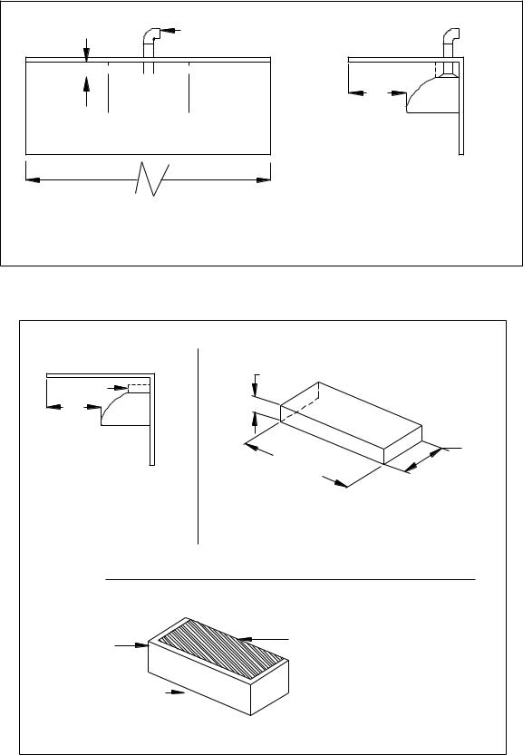
Secure Transition To Hood Using #6 x 3/8" |
|
|
|
||
|
A Center Of Round Duct Using |
To Accept Transition # 33895 |
|||
Sheet Metal Screws. Tape All Joints And Seams. |
|||||
Transition |
|
|
|||
|
|
|
|
||
Page 3 of 8 P/N 11857.00 Rev A

Outside Patio or Lanai Installation
Construction methods and installation shall comply with all local building codes. Internal ducting shall be sealed using outdoor rated metal duct tape.
The LYNX hood with stainless steel canopy is approved for installation in an outside patio or lanai area if the area is covered with a protective roof over the hood (wall style hoods are to be also mounted to a solid protective rear wall) and installed with a GFCI protected branch circuit. Roof or Wall Caps are to be sealed to prevent moisture migration to structure interior; use an outdoor rated sealant suitable for adhesion to the installation materials. See
Fig-8 for rear exhaust installation and Fig-9 for top exhaust installation.
Wall Cap
A |
A |
B |
Rear
Exhaust
A = 42" Minimum |
|
B = 30" Minimum |
Front View |
Fig - 8 |
Side View |
See Fig – 10 for structure with elevated roof/ceiling.
The Roof shall cover the top of the hood and extend a minimum of 42” from each side of the hood and 30” minimum from the outer most edges of the hood front.
Since, outdoor areas are subject to strong cross drafts it is recommended that the hood extend at least 3 – inches, and preferably 6 – inches, over either side of the cooking area to maximize the cooking discharge capture area. Cross drafts will affect the efficiency of the ventilation system and cooking discharge can escape capture by the hood/ventilation system. Be sure to plan for adequate ventilator (blower) capacity to minimize cross drafts influencing the removal of cooking discharges.
Page 4 of 8 P/N 11857.00 Rev A
The installation instruction that accompanies the hood shall be followed to ensure all safety Instructions and guidelines are adhered to. NOTE: Hood is recommended for use over domestic gas or electric appliances. Not recommended for use over solid fuel fired appliances. See Fig-10 for soffit construction
12" |
Roof Cap |


 Soffit
 A
A 

 A
A
B |
Top |
Exhaust |
A = 42" Minimum |
B = 30" Minimum |
Front View |
Side View |
|
Fig - 9 |
See Fig – 10 for structure with elevated roof/ceiling.
For installations with elevated Roof/Ceiling use a Soffit, or optional stainless steel extension
|
Constructed Soffit |
|
Soffit |
4" MIN |
|
|
||
B |
|
|
Top |
12" |
|
Exhaust |
||
Hood Widths |
||
|
||
B = 30" Minimum |
Soffit Top, Sides |
|
Side View |
& Front Shall Be |
|
|
Enclosed. Fasten |
|
|
To Top Of Hood |
|
Stainless Canopy Extension |
||
Canopy |
Fasten Wall Board |
|
Panel To Underside |
||
Extension |
||
Of Top Flange |
||
Fasten To Top |
||
|
||
Of Hood |
Fig - 10 |
|
|
||
Soffit shall be constructed of materials suitable for outdoor installation and be sealed to prevent moisture migration to structure interior.
Page 5 of 8 P/N 11857.00 Rev A
 Loading...