How it Works
Log In / Sign Up
Buy Points
How it Works
FAQ
Contact Us
Questions and Suggestions
Users
Logitech
Loading...
W
WHEEL MOUSE
2
Wingman
2
WingMan Cordless RumblePad
WingMan Force 3D
3
WingMan Formula Force GP
WingMan Formula GP
2
WingMan RumblePad
WIRED 3.5MM HEADSET WITH MIC
Wired Keyboard
Wireless All-in-One Keyboard TK820
Wireless Boombox
3
Wireless Combo MK330
Wireless DJ
Wireless DJ music system
WIRELESS DRUM CONTROLLER
2
Wireless Gamepad F710
Wireless Guitar Controller
6
Wireless Headphones For iPod
Wireless Headphones For MP3
Wireless Headset
2
Wireless M515
WIRELESS MICROPHONE
Wireless Mouse M185 Blue-Black
Wireless Mouse M185-Red
WIRELESS MOUSE M305
Wireless Music System
WIRELESS MUSIC SYSTEM FOR PC
Wireless Speaker
2
Wireless Speaker Adapter
Wireless Speaker for Ipad
Wireless Touch Mouse M600
WIRELESS TOUCHPAD
5
WONDERBOOM 2
WP R400
WP R700
WTK820
X
X100
3
X-140
X-210
X-220
X-230
X-240
3
X2-A-EMEA
X300
4
X-350
X50
X52
2
X52 Pro
X-530
3
X-540
4
X56
X56 HOTAS
2
X620
2
X-R0001
X-RB2
2
Y
Y-R0014
Y-R0016
Y-R0018
Y-R0023
Y-R0037
Y-R0038
Y-R0040
Y-R0044
Y-R0063
Y-RAY81
YRBF91
3
YRBG93
4
YRBN90
2
Y-RJ20
Y-U0018
YUU87
Z
Z-10
4
Z110
Z110 2.0
Z120
5
Z130
6
Z150 WS
Z200
8
Z205
Z207
2
Z213
25
Z-2300
Z240
2
Z-3
Z305
Z313
3
Z-3 2.1
Z-333
13
Z-340
Z-5
z-5300
2
Z 5300e
Z-540
2
Z-5400
2
Z-5450
Z-5500
3
Z-623 2.1 THX 980-000403
Z-640
3
Z-680
2
Z Cinema
3
Loading...
Loading...
Nothing found
X52
User Manual [ru]
539 pgs
2.29 Mb
1
User Manual [ru]
451 pgs
3.14 Mb
0
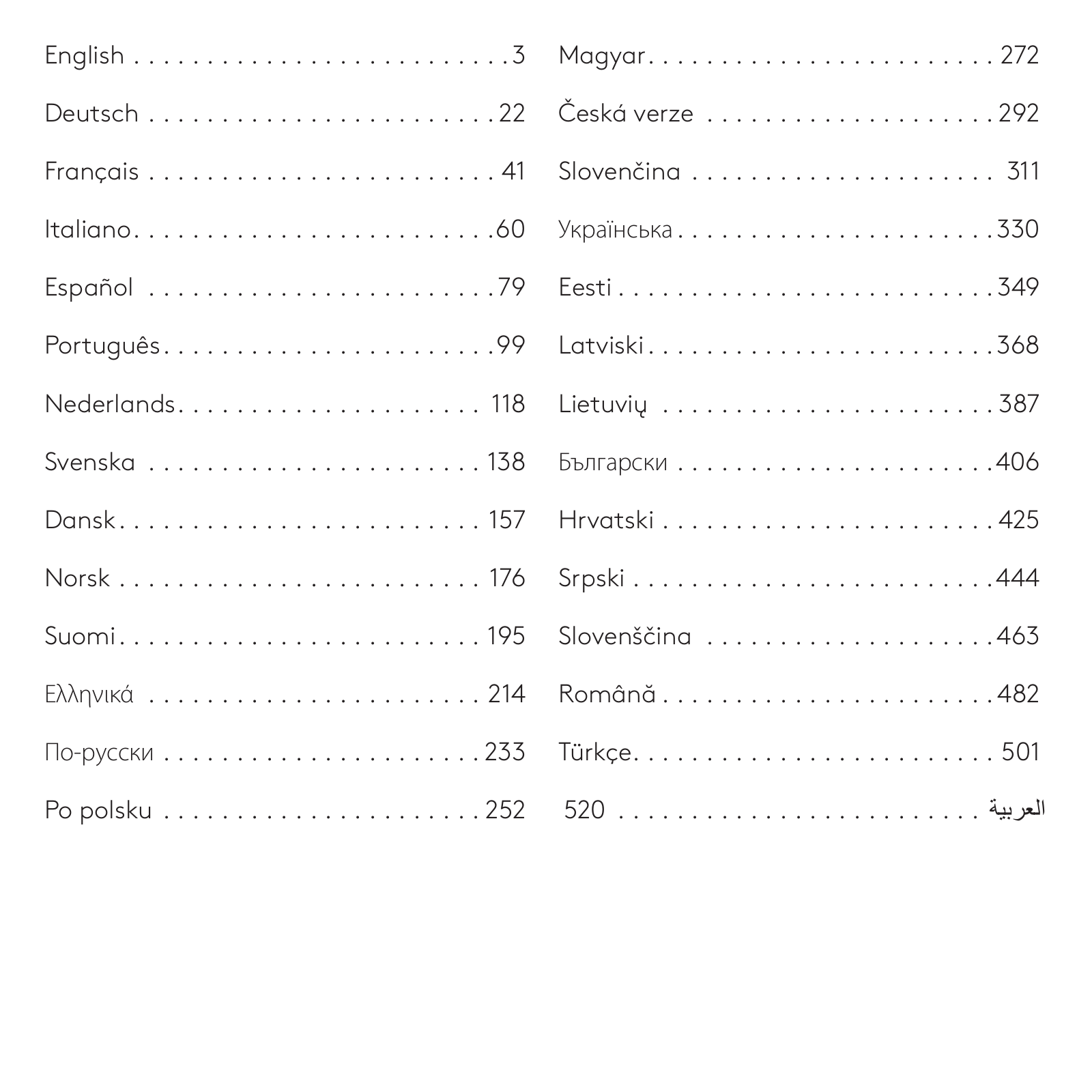
Table of contents
Loading...
Logitech X52 User Manual [ru]
...
Logitech User Manual [ru]
Download
Specifications and Main Features
Frequently Asked Questions
User Manual
Download
Loading...
+
hidden pages
Unhide
You need points to download manuals.
1 point = 1 manual.
You can buy points or you can get point for every manual you upload.
Buy points
Upload your manuals