


SM-PCP REV B
PC PROGRAM INSTRUCTIONS
Models: Power-Fin, Knight, Knight XL,
Knight Wall Mount and Armor
WARNING |
This manual must only be used by a |
|||||
qualified |
heating |
installer |
/ |
service |
||
|
technician. Read |
all instructions, |
||||
|
including |
this |
manual, |
the |
||
|
Installation and Operation Manuals, |
|||||
|
and the Service Manuals, before |
|||||
|
installing. Perform steps in the |
|||||
|
order given. Failure to comply could |
|||||
|
result in severe personal injury, |
|||||
|
death, |
or |
substantial |
property |
||
|
damage. |
|
|
|
|
|
Save this manual for future reference.

 PC Program Instructions
Contents
1. |
INSTALLATION |
|
|
Program Installation ..................................................... |
3 |
|
USB Installation............................................................ |
3 |
|
Program Setup............................................................. |
3 |
|
Starting the Program .................................................... |
4-6 |
2. |
SMART SYSTEM Status Screen ................................. |
5 |
3. |
SMART SYSTEM Graphics Screen............................. |
7 |
4. |
SMART SYSTEM Fault History Screen....................... |
8 |
5. |
SMART SYSTEM Cascade Screen ............................. |
9 |
6. |
POWER-FIN PARAMETERS |
|
|
Parameter Information Screens ................................... |
10 |
Changeable Parameters .............................................. |
11 |
Set 2: Functional Data ................................................. |
11 |
Set 4: Menu Values...................................................... |
12-19 |
7. KNIGHT, KNIGHT XL, KNIGHT WALL MOUNT, and |
|
ARMOR PARAMETERS |
|
Parameter Information Screens ................................... |
20 |
Changeable Parameters .............................................. |
21 |
Set 1: System Setup .................................................... |
21 |
Set 2: Functional Data ................................................. |
22 |
Set 4: Menu Values...................................................... |
23-29 |
8. NOTES......................................................................... |
30-31 |
2

PC Program Instructions
1Installation
Program installation
To begin installation of the program, please insert your Smart System CD into the CD drive. If you have Autostart enabled, the Smart System software screen will load. If not, navigate to your CD drive and double-click on index.html. Once the screen opens, select the program you wish to install. Follow the prompts then restart your computer.
If you wish to have the PC program icon on your desktop, click on START, and then Programs. Right click on SMART SYSTEM PC. Place the cursor over Send to >, and then click on Desktop. The icon will appear on the Desktop Screen.
USB installation
Your PC will communicate with the SMART SYSTEM control through the USB cable adapter combo included with your kit. This cable will require a specific USB driver. This driver may be installed by starting the SMART SYSTEM PC program, clicking on the Settings pull-down menu, and clicking on Comport> item. In the next menu, you will have the option of installing one of two USB drivers. Select the option appropriate for the operating system used by your PC. The necessary driver will install automatically.
Program setup
The PC will assign a ComPort to your new adapter. You will need to know the ComPort number it uses in order to tell the Smart System PC program which one to communicate with:
1.Click on Start, then Control Panel, then on the System icon (use the Classic View), then on the Hardware tab, and then on the Device Manager button. You will see a list of the hardware on your PC.
2.Double click on “Ports (COM&LPT)”. You will see an entry called “USB Serial Port (COM4)”. The ComPort number may be different on your computer but the device description will be the same. The Smart System PC program can communicate through Comports 1 – 16 on all models.
If the Comport assigned by your computer is a value larger than what is available in the Smart System PC program, you will need to manually reassign the ComPort on your computer.
3.Go back to the “Ports (COM&LPT)” area referenced above and take note of any unused ComPort between COM1 to COM16. Double click on the “USB Serial Port”.
4.Click on the “Port Settings” tab, then on the “Advanced” button. Select an unused Comport number (preferably COM1) in the range of COM1 to COM16 Click on OK. Click OK on the previous window and then close all of the other windows.
5.Restart your PC to make sure the new ComPort number is active. When you attach the USB cable to the PC, the PC should recognize the cable. The first time you start up the Smart System PC program, click on the “Settings” tab at the top of the screen, then click on “Comport”. Select the ComPort number assigned to the USB cable above.
The program displays temperatures in °F. If you wish to display temperatures in °C, click on the Settings tab along the top of the Main Screen window, and move the cursor over Temperature > in the pull-down menu. A new menu will appear, click on
Celsius.
CAUTION |
DO NOT connect a phone line to the |
|
phone jack on the front display. |
3
 PC Program Instructions
1Installation
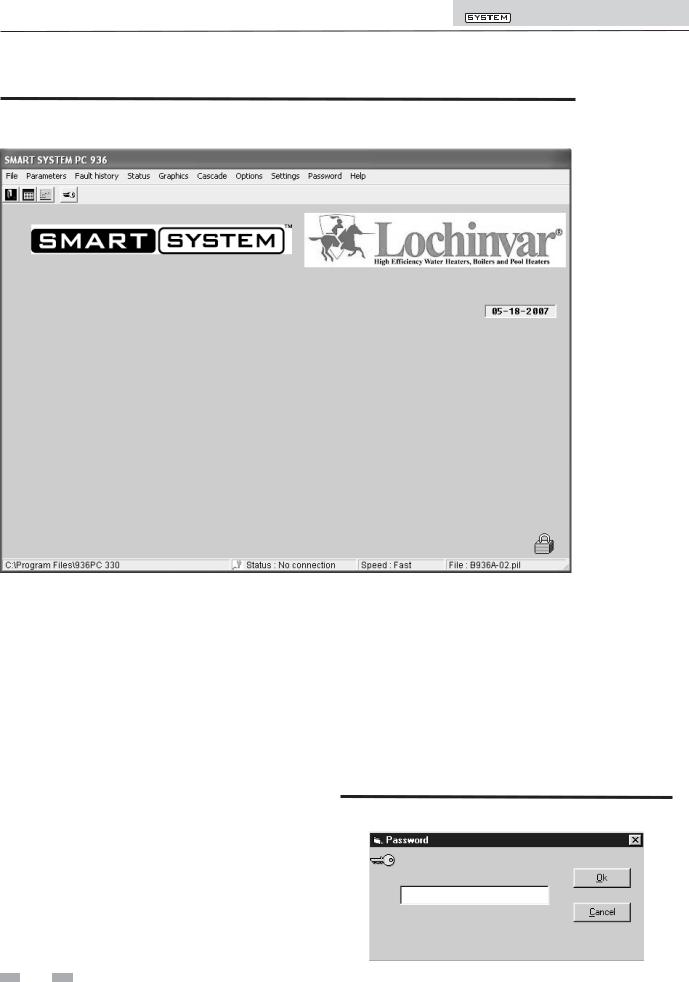
Figure 1-1_Main Screen
Starting the program
To start the program, double click on the icon (if you put it on your desktop), or click on START, then Programs, then SMART SYSTEM PC. See FIG. 1-1 on page 4.
There are two access levels for this program. The user access level allows only certain settings to be changed. The installer access level allows more settings to be changed. The program defaults to the user level when started. You will notice that a lock symbol appears in the lower right-hand corner of the window. To move to the installer level, a password must be entered. This password is located on a label on the CD-ROM case. You may enter the password by clicking on the “key” button in the upper left-hand corner of the window. A window opens in which you can type in the password (see FIG. 1-2). Note that the password is case sensitive and is in all CAPS. Click on the Ok button, or press the Enter key. You will notice that the lock symbol at the lower right-hand corner of the window has changed into a key symbol.
There are some fields along the bottom of the window (FIG. 1-1): The left field shows the location of the program. The next field shows the status of the communication between the PC and the SMART SYSTEM. This will say “No connection” when the program is started. As soon as the program sends or receives data from the SMART SYSTEM, this field will show “Connected”. The right field shows the filename of the parameter file in the program’s memory (see the following parameters).
Figure 1-2_Password Window
4
PC Program Instructions
2SMART SYSTEM Status screen
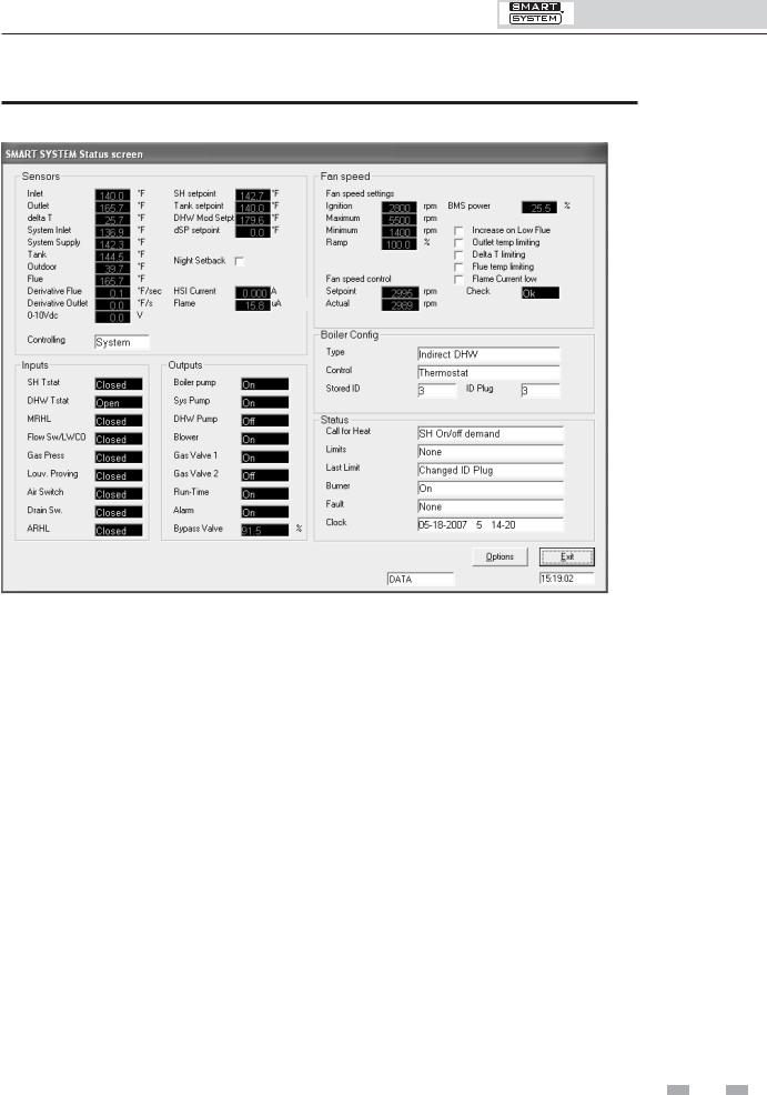
Figure 2-1_SMART SYSTEM Status Screen
To monitor and record the operation of the heater, click on the Status tab along the top of the Main Screen window (FIG. 1-1, page 4). The SMART SYSTEM Status Screen will appear (see FIG. 2-1 above). The screen is divided into several sections.
The Sensors section displays the current temperatures seen by the Inlet, Outlet, System Inlet, System Outlet, Tank, Outdoor, and Flue sensors. It also shows the delta T across the heat exchanger and the voltage being applied to the 0-10Vdc input (FIG. 2-1). The controlling sensor is shown below the items mentioned above. The default controlling sensor is the Outlet sensor. If a System Supply sensor is connected, the control will automatically use it as the controlling sensor.
The SMART SYSTEM can be programmed to use the Inlet sensor if desired. When so programmed, the Outlet sensor will be displayed for the first 3 minutes after the burner lights, and then the Inlet sensor will be displayed.
Power-fin Models Only: If a System Return sensor is connected, the control will use it as the controlling sensor, and display its reading instead.
Below the temperature readings are Derivative Flue and Derivative Outlet. These show how quickly these temperatures are changing. The control will take certain actions based on these values. For instance, if the outlet temperature rises too quickly, the control will force the heater to run at low fire.
To the right of the sensor temperature readings are the various setpoints. The SH setpoint is the setpoint the SMART SYSTEM uses during a space heating call for heat. Note that this setpoint will depend upon the outdoor temperature if the outdoor air sensor is connected. When the 0-10Vdc input is used, this setpoint will vary with the input voltage if it is used to control the setpoint. The tank setpoint is the setpoint used when a Tank sensor is connected. The DHW Mod Setpt is the outlet temperature setpoint used when heating an indirect DHW tank. The dSP setpoint is used when the inlet sensor is programmed as the controlling sensor. Below these is a check box indicating if Night Setback is active or not. Finally, the HSI Current and Flame Current are shown.
Below the Sensors section is the Inputs section (FIG. 2-1). This section displays the status of the Enable (Room Thermostat) Input, DHW Thermostat, Manual Reset High Limit, Flow Switch/Low Water Cutoff (optional), Gas Pressure Switch (optional), Louver Proving Switch (optional), Air Pressure Switch, Blocked Drain Switch, and Auto Reset High Limit Switch.
Next to the Inputs section is the Outputs section (FIG. 2-1). This section shows the status of the Boiler (secondary) pump, System (primary) Pump, DHW Pump, Blower, Gas Valve (1), Run-time Contacts, and Alarm Contacts.
5

PC Program Instructions
2SMART SYSTEM Status screen
Power-fin Models Only: If a 3-way bypass valve is installed, the display will indicate how much of the flow is not bypassed. The Gas Valve 2 output is not used.
At the top right of the window is the Fan Speed status information (FIG. 2-1). Included in the Fan Speed status are Min., Max., and Ignition fan speeds. If Ramp Delay is activated, the Ramp Delay limit is shown. The target and actual fan speeds are displayed, and if the actual speed is within acceptable limits. If the SMART SYSTEM is programmed to be controlled by a Building Management System (BMS), and programmed to have the BMS control the power from the boiler, then the percent of max. power is displayed. Finally, should select temperatures or the flame current approach certain limits, the SMART SYSTEM will force the fan speed up or down accordingly to prevent exceeding those limits. When this happens, the box next to the corresponding sensor is checked.
Below the Fan Speed status is the Boiler Configuration. This indicates the application to which the SMART SYSTEM is programmed to be used (water heater or boiler with indirect DHW), and the source of control (thermostat, BMS, or cascade depending on the model). The ID plug information is used in production to verify the correct programming of the control on Power-fin models.
Finally, the General status of the boiler is shown. Included in the General status is the active call for heat (if any), the active limits (if any), the last active limit, the burner status, the last fault, and the date and time as stored in the SMART SYSTEM.
While in the SMART SYSTEM Status Screen, you can generate a log file of the readings as the heater operates. Click on the Options button at the bottom right-hand corner of the screen (FIG. 2-1). Press the LogFile button and define a log file name and the directory you want it to be located in. Click OK. When you want to start logging data, click the Log button. The Log button will turn green to indicate that it is logging. You will also notice the filename at the top of the window, and will see the size increase as data is logged to the file. To stop logging, click on the Options button, then click on the Log button again. The Log button will turn back to gray to indicate that logging has stopped. If you desire to log data over an extended period of time, you may want to select a longer Log every time so the log file doesn’t grow too large.
You can also produce a bitmap of the window. Click on the Options button, then the Bitmap button. A bitmap of the window will be saved into the ENCONFLS directory below the directory in which the SMART SYSTEM program resides.
6
PC Program Instructions
3SMART SYSTEM Graphics screen
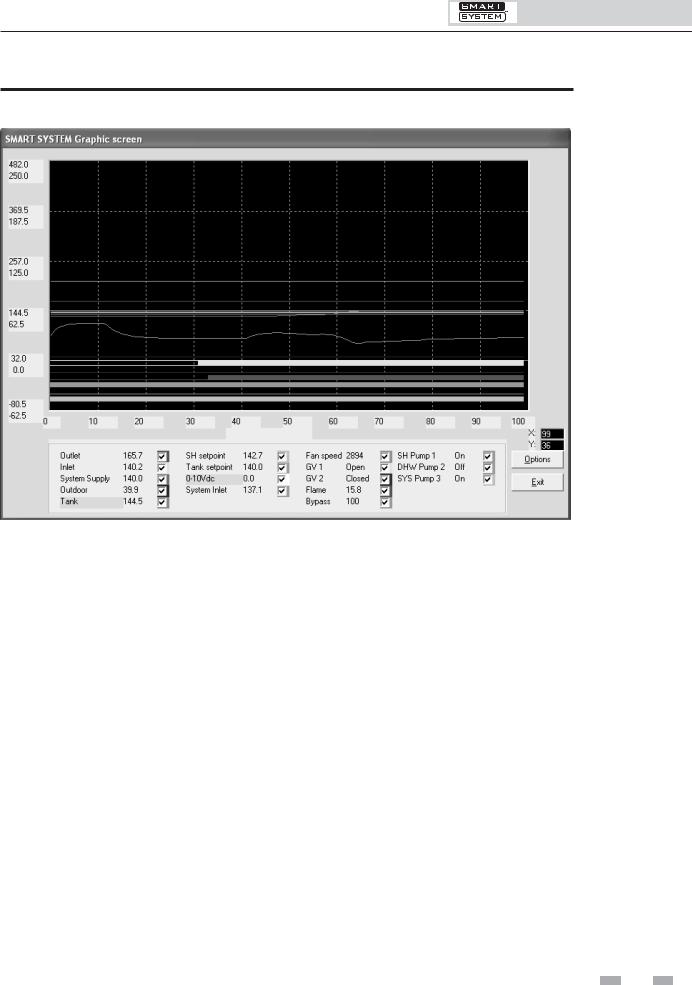
Figure 3-1_SMART SYSTEM Graphics Screen
The SMART SYSTEM Graphics Screen allows you to observe the changes in various readings while the heater operates (see FIG. 3-1). By default, the Outlet Temperature, Inlet Temperature, System Supply Temperature (if connected), Outdoor Temperature (if connected), Tank Sensor Temperature (if connected), Space Heating setpoint, Tank setpoint, 0-10Vdc input voltage, System Inlet Temperature (if connected), fan speed, and 3-way Bypass Valve (Power-fin Models Only) are plotted.
In addition, the status of the Gas Valve Output, Flame Current, and Pump Outputs are indicated by horizontal lines. When these readings are off, the line is thin; when on, the line is wide. Any of these readings can be removed from the graph by deselecting them at the bottom of the window. The current values of these readings are also displayed at the bottom of the window as depicted in FIG. 3-1.
The time scale and vertical (Y) scale can be changed by clicking on the Options button to get the Options window, and then the Up or Down buttons for the desired scale. Note that the vertical scale has two numbers for each division. The top number represents °F, and the bottom number represents °C. Press the Ok button to close the Options window. The background color of the Graphics Screen can be changed by pressing the Display button on the Options window.
As with the SMART SYSTEM Status Screen, a log file can be generated to record the performance of the appliance. Click on the Options button to open the Options window. Click on the LogFile button to create a file name and define the folder in which to put it. Once a Log File is defined, click on the Log button to start logging the readings. The Log button will turn green to indicate that the program is logging, and the log file size will appear at the top of the Graphics Screen window. Note that the file size will increase as more readings are logged. Click on the Log button again to stop logging of the readings. The Log button will turn gray again to indicate that logging has stopped.
A bitmap can also be generated of the SMART SYSTEM Graphics Screen. Click on the Options button, and then the Bitmap button. A bitmap of the window will be saved into the C:/program files/SMART SYSTEM PC/enconfls directory.
7

PC Program Instructions
4SMART SYSTEM Fault history screen
Figure 4-1_Fault History Screen
The Fault History Screen provides historical data about the operation of the SMART SYSTEM. Click on the Fault history button along the top of the Main Screen window (FIG. 1-1), and then click on Read from Control in the pull-down menu. After uploading data from the SMART SYSTEM, a window will appear with the status of numerous counters and lists of the most recent events (see FIG. 4-1 above). Included are details of the control board serial number, software version, default parameters, production date, and last service date. The number of times various faults have occurred is also shown. The last 10 faults are listed, as well as the last 10 blockings (a blocking is an event that causes the burner to shut off). In addition, the number of hours the control has operated in various states is shown, as well as the number of successful and failed ignition attempts. Finally, a count of internal checks is shown.
The total number of occurrences of certain faults are also stored in the control and shown on the left side of the screen. The column on the right shows the total occurrences since the control was built. The column on the left shows the total occurrences since the table was reset. Press the Erase table button at the bottom of the window to clear the totals in the column on the left. This will also clear the Last 10 faults and the Last 10 blockings.
Some of this information may be needed by a service technician to diagnose a problem, so provision is made to create a file in which to save this data. Click on Save file, and define a file name and the folder in which to save it. A bitmap can also be saved by clicking on the Bitmap button at the bottom of the Fault History Screen (FIG. 4-1). The bitmap file will be saved to the folder ENCONFLS located below the file in which the SMART SYSTEM program resides.
8
PC Program Instructions
5SMART SYSTEM Cascade screen
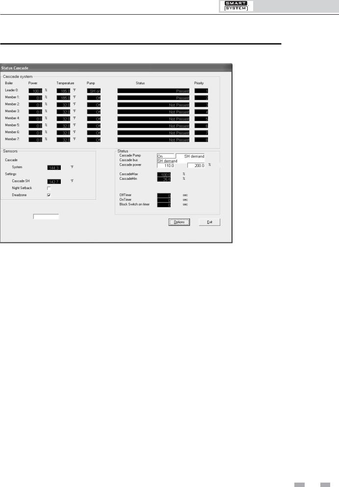
Figure 5-1_Cascade Screen
The Cascade Screen provides the status of the cascade system. The PC must be connected to the Leader (address 0) appliance. Click on the Cascade button along the top of the Main Screen window (FIG. 1-1).
The Cascade System area shows the power demand and setpoint, the boiler pump status, the boiler status, and the priority of each heater in the cascade. If a tank sensor (water heaters) or system supply sensor (boilers) is connected to the Leader heater, the cascade control will send a fixed setpoint of 215°F (102°C) (Power-fin boiler only); 185°F (85°C) (Knight boilers only) or a setpoint equal to the tank setpoint +27°F (15°C) (water heaters) and a power (% modulation) command to all the heaters as required to maintain the controlled temperature at the setpoint. On boilers, if a system supply sensor is not connected (NOT recommended), the Leader will send the space heating setpoint to all of the boilers in the cascade and each boiler will fire as required to hold their outlet sensors to this setpoint.
The Priority column indicates the order in which the heaters will fire to meet the load. This order changes every hour during the first day of operation, andevery24 hours thereafter.
The Sensors area displays the system supply or tank sensor temperature, and space heating or tank setpoint (see FIG. 5-1).
Power-Fin Models Only: Beneath this area is a check box indicating if Night Setback is active. Beneath that is a check box indicating if the Dead zone is active.
The Dead zone is active whenever the actual temperature is near the setpoint and the target modulation rate for the last boiler to fire is below its minimum firing rate. In this zone, the calculated total firing rate is held steady. Once the actual temperature goes too far above or below the setpoint, the total firing rate is adjusted accordingly.
The Status area displays several important parameters. The Cascade Pump gives the status of the system pump output, and the type of heat demand (Space Heating or DHW). The Cascade power shows the power target for the cascade, and the total power available. This target power may not be the same as the total power shown in the Cascade System area, due to the various time delays described below. The Cascade Max and Cascade Min values show the maximum and minimum fan speed percentages available in all of the heaters. The Off Timer and On Timer are used to force each boiler to have a minimum off and on time, to prevent short cycling. The Block Switch on the timer is started whenever a heater is commanded to start, and the next heater is prevented from starting until this timer times out. This allows time for the system supply or tank sensor to read the temperature change resulting from firing the last heater, before starting the next heater.
By clicking on the Options button, a log file can be defined, and logging can be started and stopped in the same way as with the Status and Graphics Screens previously described. A bitmap of the current screen can also be saved if desired.
9
PC Program Instructions
6Power-fin Parameters
Parameter information screens
By accessing the Parameter Information Screens, the installer can view all of the SMART SYSTEM parameters. The installer can also change certain specific parameters to fine tune the operation of the heater to the installation.
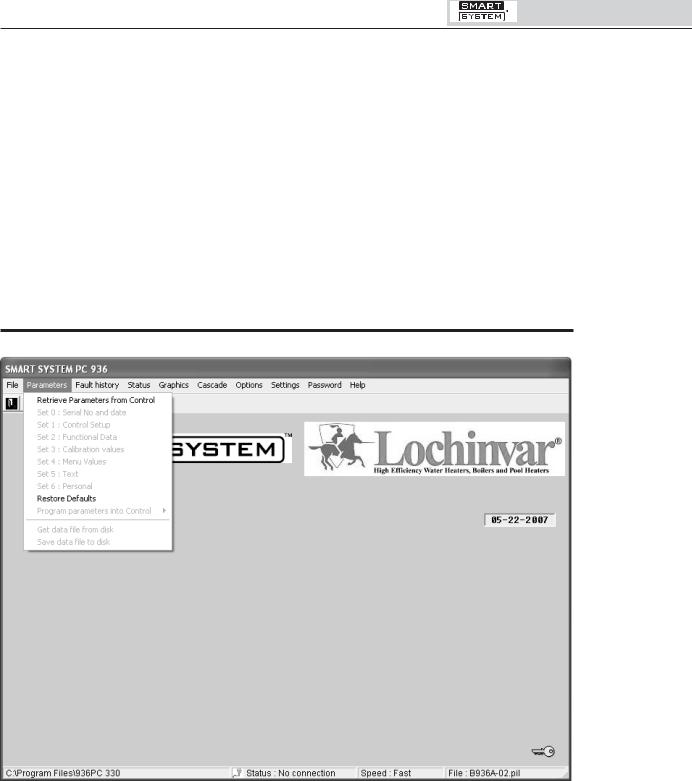
To access the parameter list, click on the Parameters button along the top of the Main Screen window (FIG. 6-1). Next click on Retrieve Parameters from Controller in the pull down menu (see FIG. 6-1). This will upload the current parameters in the SMART SYSTEM to the PC.
Figure 6-1_Parameters Pull-Down Menu Screen
Adjustable parameters are located in:
Set 2: Functional Data
Set 4: Menu Values
While many parameters are viewable in each set, only select parameters are adjustable. To make an adjustment to a parameter, select the parameter to be changed from the appropriate set. Click on the box next to the parameter and type in the value for the parameter.
Once an adjustment has been made to a parameter, it must be programmed into the SMART SYSTEM.
 10
10 
On the Parameters pull down menu, click on the Program Parameters into Control button. This will bring up another pull down menu. If a parameter was changed in just one set, select the set from the menu and click on it. If changes were made in multiple sets, select the Store Parameter Set 0-6 from the menu and click on it. This will program the new parameters into the SMART SYSTEM.
While the programming is taking place, the SMART SYSTEM will go into a lockout mode. It requires the Enter/Reset button on the display to be pressed after the programming has been completed before the appliance will be allowed to operate.
 Loading...