

Page 1
INSTALLATION & OPERATION
MANUAL
IT400
Remote Totalizer & Rate Indicator
Page 2

Liquid Controls
Sponsler, Inc.
IT400 Remote Totalizer & Rate Indicator
Page:
DOC#: MN-IT400-R2d.doc
ii
Notice
Proprietary Notice
The information contained in this publication is derived in part from proprietary data and trade secrets.
This information has been prepared for the expressed purpose of assisting operating and
maintenance personnel in the efficient use of the instrument described herein. Publication of this
information does not convey any rights to use or reproduce it or to use for any purpose other than in
connection with the installation, operation and maintenance of the equipment described herein.
Copyright 2008
Printed in the USA. All Rights Reserved.
SAFETY INSTRUCTIONS
The following instructions must be observed.
• Every effort has been made to design and manufacture this instrument to be safe for its intended
use. A hazardous situation may occur if this instrument is not used for its intended purpose or is
used incorrectly. Please note operating instructions provided in this manual.
• The instrument must be installed, operated and maintained by personnel who have been properly
trained. Personnel must read and understand this manual prior to installation and operation of the
instrument.
• An auto-resettabl e fuse internally protects this instrument. To reset the fuse, remove all power
from the unit for one minute.
• The manufacturer assumes no liability for damage caused by incorrect use of the instrument or for
modifications or changes made to the instrument.
Technical Improvements
Liquid Controls Sponsler, Inc. may modify the technical data herein without notice.
Warning: Do not open the enclosure when an explosive gas atmosphere is present.
Page 3

Liquid Controls
Sponsler, Inc.
IT400 Remote Totalizer & Rate Indicator
Page:
DOC#: MN-IT400-R2d.doc
iii
Table of Contents
Description ............................................................................................................................................ 1
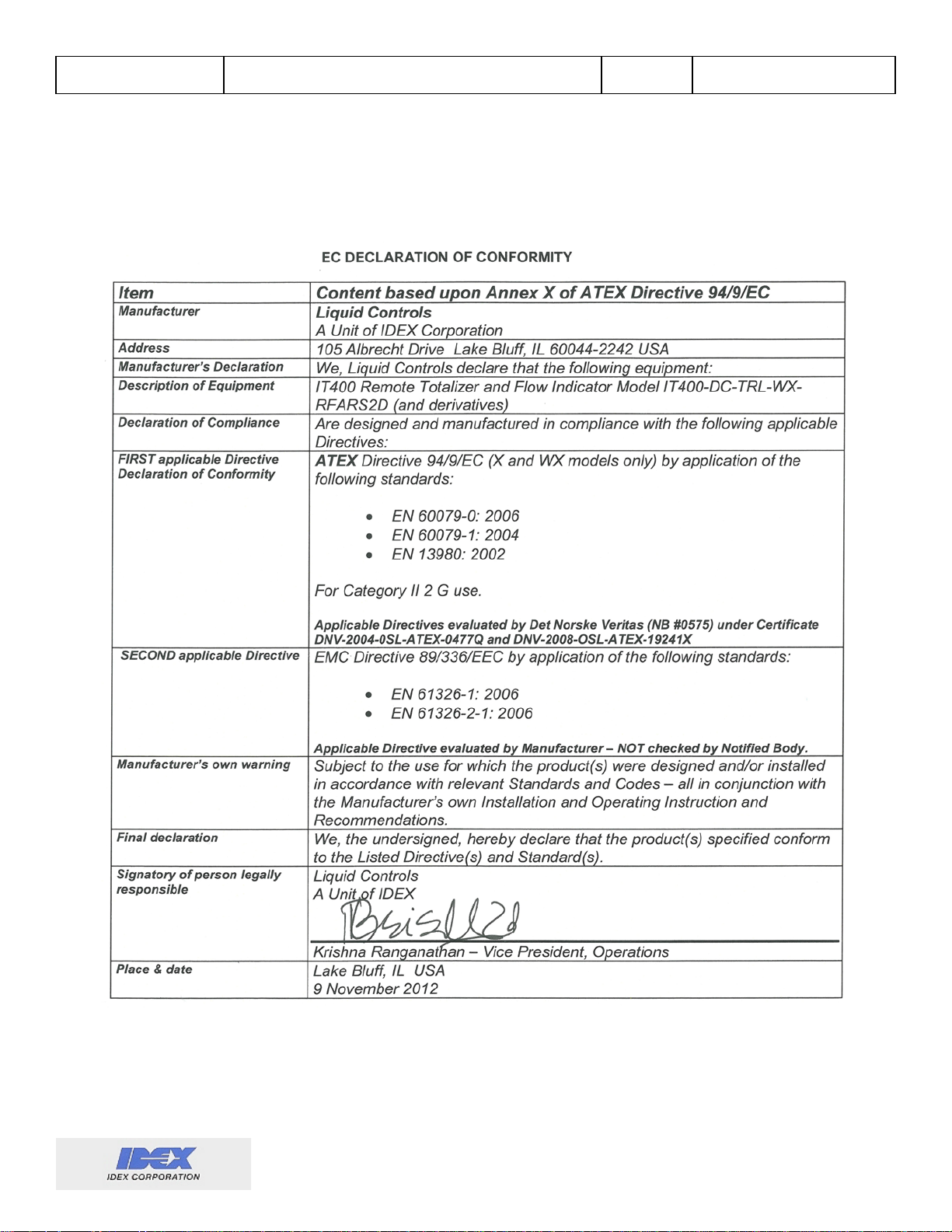
CE Declaration of Conformity ............................................................................................................ 2
Specifications .................................................................................................................................... 3
Wiring and Hookup Diagrams ............................................................................................................... 4
IT400 Operational Ov erv i ew ................................................................................................................. 8
Calibration ......................................................................................................................................... 8
Temperature Compensation .............................................................................................................. 8
Linearization ...................................................................................................................................... 8
LCD Display ...................................................................................................................................... 9
User Controls .................................................................................................................................. 10
Non-User interfaces ........................................................................................................................ 10
Inputs............................................................................................................................................... 12
Backlight .......................................................................................................................................... 13
Power .............................................................................................................................................. 13
Enclosure ........................................................................................................................................ 14
Menu System ...................................................................................................................................... 15
Button functions ............................................................................................................................... 15
Editing numbers .............................................................................................................................. 15
Menu descriptions ........................................................................................................................... 16
Appendix ............................................................................................................................................. 24
Appendix 1: Menu Quick Reference ................................................................................................ 25
Appendix 2: Coefficient of Thermal Expansion for Common Fluids ................................................. 26
Appendix 3: Menu Flow Chart ......................................................................................................... 27
Appendix 4: Manual Revision History .............................................................................................. 34
Page 4

Liquid Controls
Sponsler, Inc.
IT400 Remote Totalizer & Rate Indicator
Page: 1 DOC#: MN-IT400-R2d.doc
Description
General Unit Operation
The IT400 Remote Totalizer and Rate Indicator is a microcontroller based flow instrument capable of
translating flow in format ion and conditions to the built-in display and various outputs.
Features
• Pulse input supports turbine as well as many other pulse-type flowm et ers
• All features/configuration settings are available via field programmability
• Independent rate/t otal dis pl ay
• Magnetically operated internal switches maintain enclosure integrity
• Built-in digital multimeter and simulation functions for testing
• 2-20 point Linearization available
• Non-resettable “Grand” totalizer
• All outputs are fully opto-isolated (not RS-232)
• RS-232 port available
• Temperature compensation (RTD probe) available
• Backlight and backlight timer for low light display viewing
• Autoranging Rate display (decimal point will shift based on the size of the rate)
• Selectable power modes for customized battery life
• Available Datalogger can capture up to seven process/system values
Page 5
Liquid Controls
Sponsler, Inc.
IT400 Remote Totalizer & Rate Indicator
CE Declaration of Conformity
Page: 2 DOC#: MN-IT400-R2d.doc
Page 6

Liquid Controls
Sponsler, Inc.
Specifications
IT400 Remote Totalizer & Rate Indicator
Page: 3 DOC#: MN-IT400-R2d.doc
Display
• Total
• 8 digit 5.40mm high LCD (continuous display)
• Batch total (magnetic reset)
• Grand total (no reset)
• Rate
• 5 digit 8.66mm high LCD (continuous display)
• Range over/under limit indication
• Refresh rate: Multiple depending on power
mode (1/16s, 1/8s, 1/4s, 1s, 0.5s)
• Backlighted green w/ LED (magnetically activated
and timed)
• Dual segment low-battery warning
• Maintenance due warning
• Temperature range warning
Power:
• Internal: D Lithium battery
• Battery life: Various: typical per power mode:
1: 1yr, 2: 1yr; 3: 3.6yr; 4: 3yr; 5: 8yr
• External DC: 5 to 48VDC +/- 2 VDC reverse
polarity protected (Max: 12mA w/ backlight)
• Loop: requires 7VDC of loop supply
• Loop powered from the 4-2 0m A loop input
(non-isolated)
K-Factor range
• Pulses per gallon: 0.0000001 to 999999
Signal Input (flow)
• Frequency: 0-3000Hz
• Impedance: 10k ohms
• Magnetic
• Sensitivity: 50mV-36V (field adjustable) sine
or square wave
• Modulated carrier
• Carrier frequency 50kHz (requires external
power or loop power)
Compensation Input
• Temperature - RTD
• Two wire 10k ohm
• Coefficient of Thermal Expansion method
• Frequency
• Linearization table 2 to 20 poin ts
Engineering Unit Conversions
• Pre-programmed units: Gallons, Liters, Ft3, M3,
Pounds, BBL, KG (custom weight available)
• Custom units available with given units/gallon
• Rate and Total may have separate unit displays
Decimal Locations
• Total: Two places (and x10, x100)
• Rate: Three places (and x10, x100), autorange
Time Base
• Rates can be displayed in units per second,
minute, hour, day, and custom (in seconds)
Outputs
• Factored Pulse (Max: 150mA, 30VDC, 150mW)
• Opto-isolated open collector output
• Frequency or fixed pulse width (1, 2, 5, 10,
50, 100, & custom ms) output setting
• Output pulse Divider: 1, 2, 5, 10, 50, 100,
1000, & custom
• Alarm (Max: 150mA, 30VDC, 150mW)
• Programmable opto-isolated open collector
output
• Can be used to control totalization
(Max values at 25°C. Max combined Pulse/Alarm
output power: 190mW @ 25°C, 32mW @) 65°C)
• Rate (4-20mA)
• Factored rate to current loop output
• Programmable low and high
• Fully isolated (unless loop powered)
• Loop Voltage limit: 7-36VDC
Accuracy
• Display: ±0.01% reading (rate) or ± 1 count (total)
• Analog output: ±0.025% of fs @20°C
• Digital output: ±1 count
Environmental
• Operating: -30 to 65°C (-22 to 150°F)
• Storage: -40 to 85°C (-40 to 185°F)
Enclosure
• Explosion Proof Aluminum
• FM Approved, CSA Certified
• Class I, Division1, Groups B, C, & D
• Class II, Division 1, Groups E, F, & G
• NEMA 4X, IP66
• All openings ¾” FNPT
• Weight: 2.5lbs.
• Mount: Directly on flowmeter or Wall mount
Compliance
• CE 0575
• ATEX Ex II 2 G Ex d IIC T6 Gb (X and WX
enclosure types only)
• DNV-2008-OSL-ATEX-19241X
Communications
• RS-232
Datalogger
• Up to four triggers (including timer)
• Up to seven system values
• Real-time clock
• RS-232 or Internal SD/MMC Flash media card
Other features
• EEPROM setup storage (>100 year retention)
• All features/settings are field programmable.
Convenient number input via 0 -9 rotary switch and
two pushbuttons
Page 7

Liquid Controls
Sponsler, Inc.
IT400 Remote Totalizer & Rate Indicator
Page: 4 DOC#: MN-IT400-R2d.doc
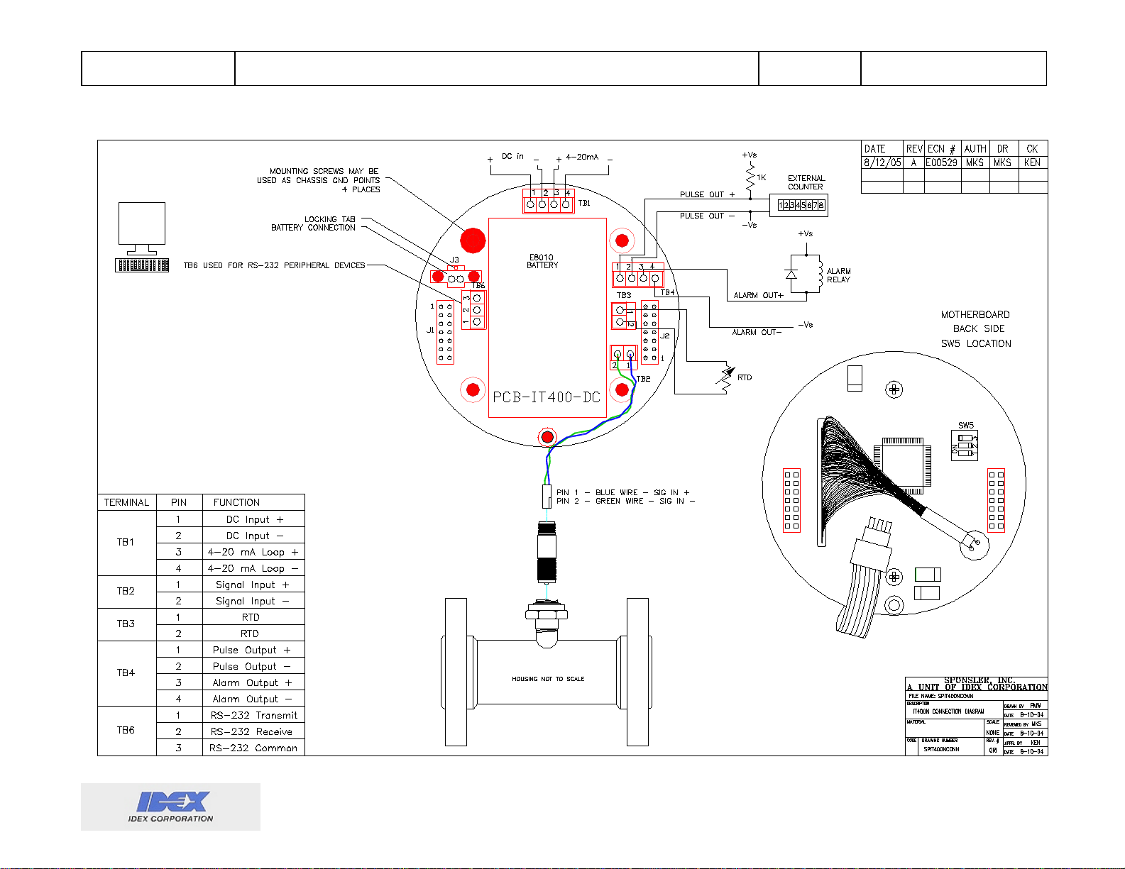
Wiring and Hookup Diagrams
The IT400 has many connections all made through the bottom/mounting board. It is
recommended to remove the battery when connecting wires to the connectors and when plugging
the connectors into their sockets.
Wiring
In order to maintain the rated CE marking, the following practices must be followed:
• All wires connected to the IT400 must be shielded (exception: SI supplied signal cable).
o All shields must be connected to one of the internal mounting screws to achieve their
ground connection.
o It is recommended that the non-IT400 end of these shields is left unconnected. This
will help avoid ground loops and unexpected behavior.
o It is recommended that only one spade type terminal be used on each of the screws.
Care should be taken to avoid shorting any spade with other circuitry on the mounting
board. If a longer screw is needed to attach the shielding spade, then the screw
must be chosen to ensure at least one extra thread of space behind the screw. The
hole depth is approximately 0.250 inches.
o Shields should not cover more than one pair of signal wires at a time.
• The IT400’s chassis must be connected to an earth ground via the screw attached to the
outside of the unit. At least a 12 AWG preferably green wire is recommended.
• All connections are to be made to the unit via rigid conduit.
• All connected wires must not exceed 98’ length.
• DC powered devices requiring the CE marking must be 4-20mA loop powered.
If no wires are required for a particular installation; the only requirement is the chassis ground
connection.
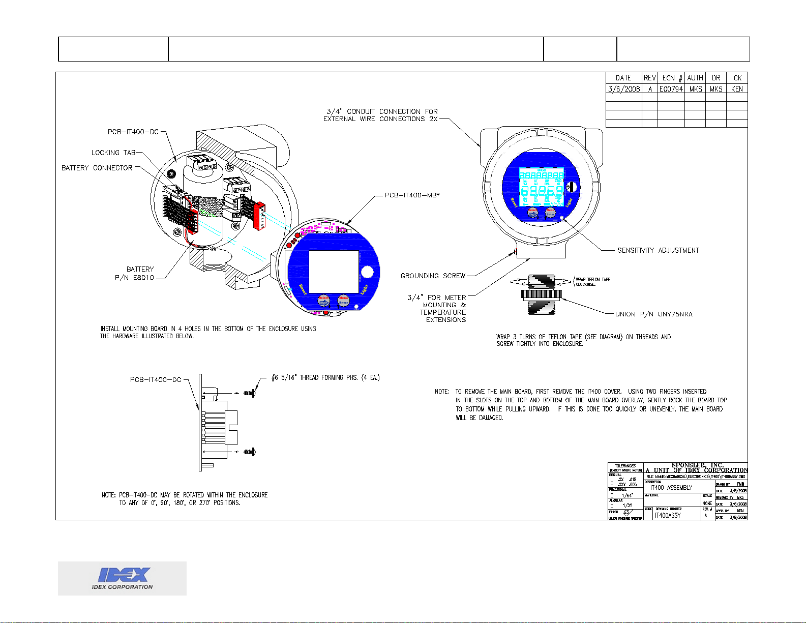
Battery Removal and Installation
Battery Replacement:
- E8010 from Liquid Control s Sponsler, Inc.
- TL-5930/F from Tadiran Batteries, Ltd.
Battery Removal:
reset the totalizer appears, the totalizer/grand totalizer/service timer will be saved to memory.
Using two fingers inserted in the slots on the top and bottom of the main board overlay, gently rock
the board top to bottom while pulling straight out. If this is done too quickly or unevenly, the main
board will be damaged. After the main board is removed, the battery is accessible by opening the
hook-loop strap. Once the battery is loose, the battery clip is removed by compressing the locking
tab on the connector (locking tab is on the top of the connector {J3}) and pulling it out.
Battery installation: Reverse the pr ocess for installation. Ensure the battery connector key is in the
proper orientation pri or to inser ti on.
The internal battery may only be replaced with one of two batteries:
Unscrew the IT400 cover, press and hold the menu button until the option to
Page 8
Liquid Controls
Sponsler, Inc.
Diagrams:
IT400 Remote Totalizer & Rate Indicator
Page: 5 DOC#: MN-IT400-R2d.doc
Figure 1 IT400 Connections
Page 9
Liquid Controls
Sponsler, Inc.
IT400 Remote Totalizer & Rate Indicator
Page: 6 DOC#: MN-IT400-R2d.doc
Grand
TB1
J3
1
2
TB6
1
J1
TB5
4
3
2
1
TB4
4
3
2
1
TB3
3
2
1
TB5
1
2
1
2
1
TB2
JP3
Grand
LIQUID CONTROLS GROUP
SPONSLER
Precision Turbine Flowmeters
A UNIT OF
IDEX
CORPORATION
2363 SANDIFER BLVD. WESTMINSTER, SC 29693
1.864.647.2065 WWW.SPONSLER.COM
I
T
4
0
0
b
e
r
m
u
N
LIQUID CONTROLS GROUP
SPONSLER
2363 SANDIFER BLVD. WESTMINSTER, SC 29693
I
T
4
0
0
Precision Turbine Flowmeters
A UNIT OF
IDEX
CORPORATION
1.864.647.2065 WWW.SPONSLER.COM
b
e
r
m
u
N
Figure 2 IT400 Board Stack Assembly and Battery Removal
Page 10
Liquid Controls
Sponsler, Inc.
IT400 Remote Totalizer & Rate Indicator
Grand
I
T
4
0
0
r
e
b
m
u
N
2363 SANDIFER BLVD. WESTMINSTER, SC 29693
1.864.647.2065 WWW.SPONSLER.COM
LIQUID CONTROLS GROUP
SPONSLER
Precision Turbine Flowmeters
A UNIT OF
IDEX
CORPORATION
Page: 7 DOC#: MN-IT400-R2d.doc
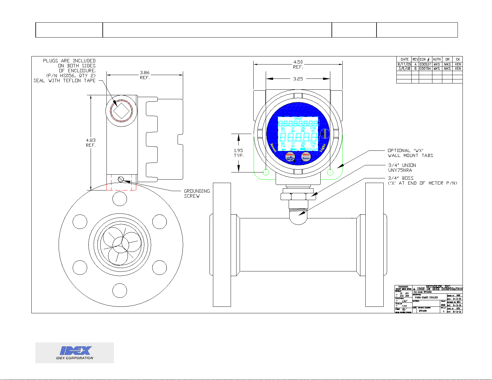
Figure 3 Meter Mounting and Dimensional
Page 11

Liquid Controls
Sponsler, Inc.
IT400 Remote Totalizer & Rate Indicator
Page: 8 DOC#: MN-IT400-R2d.doc
IT400 Operational Overview
The IT400 flowmeter system will perform the necessary calculations to provide the user with an
optional temperature compensated and optional linearized output of the following values:
• Rate
• Total
• Grand total
• Errors/warnings
• Various outputs
Calibration
Calibration of the IT400 is accomplished using either a linear K-Factor (pulses per gallon) or a
linearized K-Factor linearization table (when the linearizer is enabled). Independent unit conversion
factors and decimal points are available for the rate and total displays. Calibration and configuration
data are stored in an onboard EEPROM for permanent storage. Calibration of the IT400’s reference
circuitry is factory set and is not user accessible. Calibration of the IT400’s reference circuitry should
be performed by factory trained service personnel.
Temperature Compensation
The temperature compensator utilizes a platinum RTD to detect the process temperature. Process
temperature is used in conjunction with the reference temperature and Coefficient of Thermal
Expansion of the measured liquid (menu items) to adjust the rate and total values. When the
temperature compensation is enabled, the temperature warning annunciator (thermometer on the
LCD) will indicate when the process temperature is out of a programmable range. Optionally, an
alarm output as well as a totalizer inhibit function can also be tied to this temperature warning.
Various Coefficient of Thermal Expansions and their reference temperatures can be found in the
appendix. The temperature circuit and associated algorithm, when enabled, increase the IT400
current consumption fr om the power source and diminish battery life if running solely from the battery.
A programmable delay function has been provided in order to minimize the impact of the temperature
sampling on the battery life. The delay feature specifies the number of seconds between temperature
value samples. The higher the delay, the longer the battery will last.
Linearization
The linearizer utilizes a linear interpolation algorithm to calculate the rate and total based on a set of
calibration data points pr ogrammed by the user. The linearizer has21 points, the first point (lowest) is
automatically set at zero hertz, the remaining 2 to 20 are user programmable. The linearizer table
must have at least two data points in addition to the first (fixed) point and must be ascending in
frequency from the first point to the last. To have fewer than 20 points in the linearizer table, after the
last desired linearization point add one additional point and set the frequency at zero. Zero is an
invalid frequency; this will indicate the end of the table. The IT400 will not allow frequencies to be
entered out numerical order. Frequencies between zero and the first programmed point will use the
K-Factor of the first programmed point.
Page 12
Liquid Controls
Sponsler, Inc.
8 digit
IT400 Remote Totalizer & Rate Indicator
Page: 9 DOC#: MN-IT400-R2d.doc
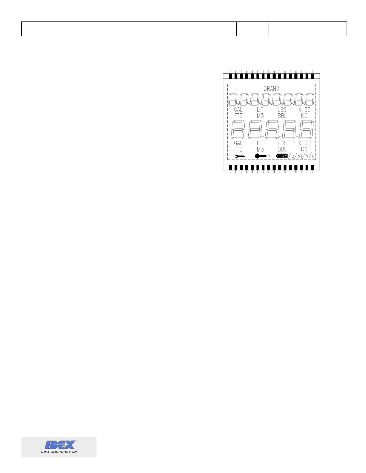
LCD Display
The LCD display has three main areas: The 8 digit totalizer,
5 digit rate indicator, and the annunciators.
• The 8-digit totalizer shows the total number of units
of volume through put of the flowmeter since the last
time the totalizer was reset. The totalizer is
resettable by 2 methods, via a magnetic reed sw it ch
in the lower left side of the unit and by menu. Th e
grand total is displayed as long as a magnet is
placed near the top of the face of the unit. The word
"GRAND" indicates the displayed value is the grand
total. Grand should be activated prior to battery
replacement to save total/grand total values to nonvolatile memory. Engineering unit annunciators
display the units and decimal place selected to compute total and grand total values. The
grand totalizer uses the same engineering unit as programmed for the totalizer.
• The 5-digit rate display shows the rate of the flowmeter throughput. If the rate exceeds the
high flow warning setpoint, "-oL-" is displayed. “-UL-“ is displayed when the rate is less than
the low flow warning setpoint. The warning is displayed until flowrate within these setpoints
resumes. The totalizer is not affected by this warning unless programmed to inhibit totalizer
when out of range. The range limits are established by the flow warning setpoints (Warning
menu) in the menu system. Indicators on the display also show the engineering units of
volume, time and decimal place used to compute the rate value.
Note: When the Grand Total magnetic reed switch is activated (and GRAND is displayed on the
screen), the rate display will display the current rate regardless of the range limits. This is
helpful when troubleshooting flow condition problems when the low rate setpoint is set above
zero.
• Refresh rate of the display of the unit happens at pre-determined intervals depending on the
selected power mode (see “Power”). Once the power mode is programmed (in the menu), the
refresh rate is fixed. This prevents a low refresh rate from being automatically selected which
could cause measurement delay.
• Other display annunciators. These are warning indicators and do not inhibit the operation of
the unit (unless explicitly enabled to do so by the alarm opti o n). These indicators may
however indicate the condition causing an inaccurate reporting of rate or total information.
o Wrench – The service annunciator is user programmable to a specific amount of
“turbine hours” (activ e flowmeter hours).
o Thermometer – The thermometer annunciator is displayed continuously any time the
temperature compensator is enabled and the process temperature is out of range.
o Battery – The battery annunciator is composed of two segments. The segments
indicate the level of the battery charge, like an automotive gas gauge.
Two segments – The battery is within normal operating voltage range.
One segment – A replacement battery should be acquired and installed. This will
also cause high temperature range on the temperature circuit to be reduced.
Total
5 digit
Rate
Page 13

Liquid Controls
Sponsler, Inc.
IT400 Remote Totalizer & Rate Indicator
Page: 10 DOC#: MN-IT400-R2d.doc
No segments – The batter y must be replaced to guarantee accur a te r epor ti ng .
User Controls
There are two main groups of user controls, internal and external. The internal controls are only
accessible when the enclosure cover is removed. The external controls are magnetically accessed
by strategic placement of a magnet along the outside of the unit.
• Internal
o Menu / Enter Button – This button is used primarily within the menu system. Press this
button at any time during RUN mode to enter the menu system. Note: the higher the
power mode, the longer the button will need to be held down for it to trigger the menu
system.
o Select / Digit Button – This button is also used primarily within the menu system.
However, when the temperature compensation option is purchased and enabled,
pressing this button while in RUN mode causes the 5-digit display to indicate the
current process temperature in degrees Fahrenheit.
o Number Dial – The number dial is only used while selecting values or editing numbers
while in the menu system. The number dial is disabled in RUN mode.
• External
o Magnetic Switches – There are three magnetically activated reed switches located
around the edge of the IT400 (indicated on the front panel with yellow text). These
switches allow external activation of the following functions:
Grand – The following actions are taken when the grand reed switch is activated:
The total display will indicate the value of the grand totalizer.
The rate display will indicate the current rate regardless of any out of range
warning conditions.
The GRAND annunciator will indicate.
The IT400 will store the values of the grand totalizer, the totalizer, and the
elapsed service time to non-volatile memory. This is useful if the IT400 is to
be removed from service (replace bat ter y, recalibrate, etc).
Light – When activated, the backlight timer will be engaged according to the chart in
the Backlight section.
Reset – When activated, the main totalizer will be reset.
Note: The internal user controls are described in more detail in the Menu section.
Non-User interfaces
Non-user interfaces are those that are wired to external devices. 4-20mA rate output and open
collector pulse output are standard, open collector alarm output, RS-232, datalogger, and real time
clock interfaces are optional.
• 4-20mA rate output
high setpoints.
is a linear representation of flow rate between the progra mmed low and
Example: A flowmeter has a calibrated range of 10 to 100gpm, the desired low and
high setpoints of the 4-20mA output are 10 and 100 respectively. Using these values,
the IT400 will calculate and output the proper current reading for a given flowrate.
Page 14

Liquid Controls
Sponsler, Inc.
IT400 Remote Totalizer & Rate Indicator
R – Rate
Z – Reset Totalizer
K – K Factor
T – Total
Q – Total CF
L – Linearizer Table
G – Grand total
W – Rate CF
F – Process Temperatur e (Deg F)
C – Capture Data (Trigger a datalogger event)
Page: 11 DOC#: MN-IT400-R2d.doc
Given a flow rate of 25gpm, the current loop reading will be 6.667mA. The output
engineering units are the same as for the rate display.
Note: For loop powered operation, refer to the Power section.
Note: The IT400 requires 7VDC of the loop supply.
• Pulse output
is an open collector design. A pull up resistor is required for interface with most
systems. An output pulse occurs with each increment of the totalizer if a pulse output divider of
1 has been programmed. For programmed pulse divider values other than 1 the output pulse
will occur at the divided value. Functions for a frequency output, pulse width, and pulse output
divider are programmable. When the frequency output is not selected, pulses are output in
bursts at each refresh.
Example: The totali z er incr em ents 15 puls es ( over the last refresh time) and the pulse
output divider is 5. The number of output pulses that will be generated will be 3.
Note: If the output pulse width programmed exceeds the time required to output the proper
number of output pulses an E will be displayed in the left-most character of the total display.
The IT400 will output as many pulses as time permits at the programmed pulse width.
Example: At a maximum flow of 900gpm the proper number of output pulses is 15 per
second, but the pulse width is programmed to 100ms and the pulse divider to 1. The 15
pulses would take 1.5 seconds (15x100ms); only 10 pulses would be outputted. Either
the pulse width must be reduced or if acceptable the divider increased.
Guideline: calculate the maximum output pulse width:
Maximum pulse width = 1/(output pulses per second/output pulse divider)
Using the example above: 1/(15/1) = 66.6ms is maximum pulse width.
• Alarm output• is an open collector output that can be used to externally indicate the presence
of several out of range conditions. These conditions include: temperature, flow rate, and
battery level. The ranges of temperature and flow rate are edited in their respective sections of
the Menu system. The Battery low level is factory set. Any Alarm condition of the enabled
alarms will activate the alarm output. Identical to the output pulse, a pull up resistor is required
to interface with most systems.
RS-232 interface
allows calculated values of the unit to be viewed upon request. To use this
interface, a serial device (computer or datalogger) is used to poll the IT400 by sending one of
the listed letters (the letter by itself) to the serial port. No carriage return is necessary. The
IT400 will reply with the requested data and a CR+LF. The BAUD rate is fix ed at 9600 ba ud
8N1. Currently, the datalogger data can only be captured via the RS-232 port. The func tions
available on this interface are:
Note: Using the RS-232 interface when loop powered will cause errors in the loop reading.
Page 15

Liquid Controls
Sponsler, Inc.
2147498935, 1073, 919.532, 37211, 32.2, 58.71818, 0
2147498945, 1227, 919.385, 37365, 32.0, 58.72917, 0
Date/Time: Mon Jan 18 2038 13:14:54 GMT-5:00:00
Warnings: 0:
• Datalogger
use this interface, a serial input device (computer or printer) is used to capture the data from
the IT400. Refer to the menu section of the manual to see the data that can be captured and
what triggers are available. Each line of data is terminated by a CR+LF combination (0x0D
and 0x0A). There are two data format outputs available, DB and non-DB:
DB Format: The DB format lists the enabled data in the following order: Time, Total, Rate,
Grand Total, Temperatur e, K-Factor, and Warnings. Units are the same as displayed on the
LCD. The time listed is the “UNIX” time or the number of seconds from the UNIX Epoch time
(Jan 1, 1970, 0:00:00 GMT). No Daylight Savings Time (DST) or time zone adjustment is
made. Example:
Non-DB Format: The non-DB format lists the enabled data in the same order as in the DB
format, but will be listed one item per line. In addi ti o n, this format shows the engineering units
of each value. The date/time is adjusted for local time zone as set in the menu. DST is not
included as this would allow duplicate time stamps. Example:
IT400 Remote Totalizer & Rate Indicator
Page: 12 DOC#: MN-IT400-R2d.doc
allows various working data to be captured based on several different triggers. To
2147498937, 1104, 919.687, 37242, 32.2, 58.71818, 0
2147498939, 1135, 919.506, 37273, 32.2, 58.71818, 0
2147498941, 1165, 919.557, 37303, 32.2, 58.71818, 0
2147498943, 1196, 919.609, 37334, 32.2, 58.71818, 0
Total: 98 G
Grand Total: 36235 G
Temperature: 32.0F
K-Factor: 58.72917 P/G
• Real-time clock
maintains the current date and time for use with the datalogger. Each
datalog event is preceded with the current date and time. Time is calculated by maintaining
the number of seconds since the UNIX Epoch time (Jan 1, 1970, 0:00:00 GMT). The real-time
clock does not increment unless the IT400 is power ed (either by DC-in, battery, or 4-20mA).
When the battery is replaced, the internal clock will be slow by the amount of time between the
time the menu is entered (just prior to removing the battery) and the time the IT400 is again
powered (after the battery replacement). The real-time clock can be set in the menu system
and is only available when the datalogger option is purchased.
Inputs
The IT400 has four inputs: RS-232 interface, user interface, temperature, and input signal.
•
RS-232• interface is described above.
User• interface is described above.
Temperature input is a standard 2-wire platinum RTD te mper a tur e pr obe ( 0.38 5 TCR ) . The
temperature probe is typically mounted within a few inches downstream of the attached
flowmeter. The temperature input will increase the drain rate on the battery when the IT400 is
battery powered. The temperature input is ignored if the temperature compensator is disabled.
Page 16

Liquid Controls
Sponsler, Inc.
Page: 13 DOC#: MN-IT400-R2d.doc
DC
4-20mA
Battery
value
Backlight
in - RUN-
Backlight
Yes
Don’t Care
Don’t Care
Non-Zero
ON
ON
No
No
Good
Non-Zero
Timer
ON
No
No
Low
Don’t Care
Manual
OFF
No
Yes**
Good
Non-Zero
Timer
ON
No
Yes
Don’t Care
Don’t Care
Manual
OFF
Don’t Care
Don’t Care
Don’t Care
DI SABLED
Manual
OFF
Don’t Care
No
Good
ALWAYSoN
ON
ON
• Signal
IT400 Remote Totalizer & Rate Indicator
input from practically any frequency generating device producing a sinusoidal signal, a
square wave pulse or can be connected to a modulated carrier pickup coil.
Sinusoidal signal: low amplitude crossing signal that doesn’t exceed the IT400’s input
specification. This signal can come directly from the pickup coil sensing rotation of the
attached Sponsler, Inc. turbine flowmeter or other flowmeter device.
Square signal: any zero referenced pulse that doesn’t exceed the IT400’s input
specification.
Modulated carrier: derived by modulating a carrier signal of the pickup coil caused by
the change in impedance resulting from the rotor blades passing in proximity to the coil.
This is an inductive coil therefore there is no drag on the rotor. MC coil operation is
factory enabled only. MC coil operation requires DC or loop power.
Note: SW5-3 must be “On” for MC coil operation when externally DC powered.
Backlight
The backlight is controlled by a combination of system parameters. The following table lists the
operation of the backlight and how it is controlled by these vari ous s y s tem para met er s:
BLI TE
Powered
Powered*
Condition
in Menu
* SW5-1, SW5-2, & SW5-3 “On”.
** SW5-3 “Off” (4-20mA loop to power modulated input and battery to power main circuit).
*** If the timer is set to ALWAYSoN, the battery will last about two months when not DC powered.
The front panel magnetic reed switch activates the backlight regardless of anything (as long as power
is applied). Backl ight activation may increment one additional input pulse and will cause 4-20mA
errors.
Power
The IT400 may be powered externally by any 5-48VDC source, 4-20mA loop, internally by battery, or
by a combination of these. Power consumption is affected by programmed options, inp ut si g nal
frequency, and the programmed power mode.
•
External Power
o DC: 5-48VDC
o 4-20mA Loop: used to power the IT400 or just the modulated carrier circuit (which
requires more voltage than is available from the battery). The IT400 requires 7VDC of
the loop supply.
Page 17

Liquid Controls
Sponsler, Inc.
Main
Power
Modulated
Power
Yes
Yes*
No
Off
Off
On
External
External
No
No**
No
On
On
On
Loop
Loop
No
No**
Yes
On
On
Off
Battery
Loop
Approximate
Battery (years)
0
500
0 500
0
6.5
500
3.2
0 500
0 500
• Internal Battery
external power sources. Battery life estimates are in the Power Mode chart below and are
affected by the options enabled. The battery may be replaced at any time with the only side
effect being a loss of normal operati on (all calibration and configuration information is
maintained). Total, Grand Total, and service hours may be saved at any time by activating the
Grand Total display or by entering the menu system. Upon system startup, the saved values
will be retrieved.
IT400 Remote Totalizer & Rate Indicator
Page: 14 DOC#: MN-IT400-R2d.doc
functions either as a primary power source or as a backup to either of the
External
DC
Loop
Isolation
Battery
Powered
SW5-1 SW5-2 SW5-3
IT400
Carrier
*For External power, the loop isolation switches SW5-1, 2 must be “Off” (isolated).
** Loop powered operation; the loop isolation switches SW5-1, 2 must be “On” (non-isolated).
• Power Mode
: controls the refresh rate of both the display and outputs of the IT400 and is a
user selectable menu item. Refresh times and approximate battery life are in the following
table:
Mode
Refresh Input frequency
1 16 refreshes/s
2 8 refreshes/s
3 4 refreshes/s
4 1 refreshes/s
*Battery life calculations are worst case based on continuous flow , enabled linearizer,
temperature compensator, 4-20mA output, and pulse output.
Enclosure
The IT400 is contained in an explosion proof enclosure. This enclosure is typically meter mounted
via a union or a temperature extension (consult factory for lengths and applications). There is
typically a short cable (4 feet) that connects the IT400 to an external temperature probe (a few inches
downstream). Rigid conduit is recommended for this connection to maintain the explosi on pr oo f
rating of the enclosure and to maintain CE marking.
5 2s/refresh
Page 18

Liquid Controls
Sponsler, Inc.
IT400 Remote Totalizer & Rate Indicator
Page: 15 DOC#: MN-IT400-R2d.doc
Menu System
The IT400’s menu system is designed to allow a simple means of entering all of the data required for
the system to perform its calculations. This section steps through the menu system and provides a
description of each item. To enter the menu system, simply press Menu.
Button functions
Menu / Enter – The menu button advances through the menu system. When editing values, this
button provides the “enter” function. Note: The menu may be exited while viewing any main menu
item by pressing and holding Menu, then pressing and holding Select, then releasing Menu, next
releasing Select.
Select / Digit – The select button is used to change values and edit numbers. To edit a displayed
number, Select is pressed to allow editing. When editing num bers, each press of Digit shifts right
the digit to be edited. When selecting between two values, Select is used (this includes yes/no,
ENABLED/DI SABLED, and pos/neg)
Number – The number dial is used to set the current displayed item to a specific value. When editing
numbers, the flashing number will change according to the number dial. When editing decimal
placement of a number, the decimal point will change according to the number dial.
Editing numbers
Some menu items require the editing of a number. All three controls are used to edit the number.
Here is a short example of editing the low temperature warning set point :
1. Number to be edited is displayed:
2. Press Select to edit the number.
3. If the number can be positive or negative, press Select to toggle between
positive (PoS) and negative (NEG).
4. Press Enter to accept the desired sign.
5. Next, the actual number can be edi te d. Num ber s are edit e d
from left to right. The digit that is currently being edited will
flash. Use the Number dial to change the flashing number to
the desired value. If no change is needed, do not move the Number dial.
6. Press Digit to move the edit focus to the next digit. Repeat these steps as
necessary to edit all the digits in the number.
7. Press Enter to accept the changes to t he nu mber.
8. If the number can have a decimal, the current decimal location will flash. Use
the Number dial to change the flashing decimal to the desired location. If no change is needed,
do not move the Number dial.
9. Press Enter to accept the decimal loca ti on.
10. In most cases, an opportunity to re-edit the number is presented.
POS
T MPL o
- 350.0000
t mpLo
NEG
t mpLo
350.00000
T MPL o
Page 19

Liquid Controls
Sponsler, Inc.
IT400 Remote Totalizer & Rate Indicator
o
r ef t
Page: 16 DOC#: MN-IT400-R2d.doc
Menu descriptions
The menu is composed of a list of editable items which control the operation of the IT400. This is a
listing of all of the menu items. The IT400 reverts to the Run Mode if no user input is detected within
30 seconds while viewing any of the following top level menu items.
1. Reset Totalizer
Resets the totalizer without using an external magnet. If the totalizer reset is set to
no, the subsequent submenu is not displayed.
1.1 Reset Totalizer Done
This is an informational message that indicates that the main totalizer has been
reset.
2. Temperature Compensation E na ble
Displayed only if purchased as an option. Temperature compensation can be
enabled or disabled. If compensation is dIsabLed, the next two sub-menus are
skipped.
2.1 Reference Temperature
Temperature at which the Coefficient of Thermal Expansion is referenced. The
temperature units are degrees Fahrenheit and must match the Coefficient of
Thermal Expansion used in the next item (and is listed in the Appendix).
2.2 Coefficient of Thermal Expansion
The Coefficient of Thermal Expansion for select fluids can be found in the
Appendix.
RST No
ToTAL
r st done
t ot aL
ENABLED
t c o mp
f 60.000
0.0001015
t coef
Displayed only if purchased as an option. Linear interpolation can be enabled or
disabled. If linearization is dI SABLEd, the next three sub-menus are skipped.
Permits the editing of the linearizer table and is only set if the linearizer has been
enabled. If set to no, the linearizer table will not be edited and the menu system
jumps to menu 4 (K-Factor) below. If the table is to be edited, the menu will step through the list of
points in the order of frequency then K factor. The frequency values must be ascending starting with
the first point being the lowest.
Note: To enter a table of fewer than 20 points in the linearizer table, after the last desired linearization
point add one additional point and set the frequency to zero. Example: For 15 point linearization, set
the frequency for point 16 to zero.
Note: The table must have at least two points.
3. Linear Interpolation Enable
3.1 Linear Interpolation Table Edit
ENABLED
LI NER
edI t no
TABLE
Page 20

Liquid Controls
Sponsler, Inc.
IT400 Remote Totalizer & Rate Indicator
Page: 17 DOC#: MN-IT400-R2d.doc
3.2 Frequency Input
Permits setting of the frequency of a given run in the linearizer. The number listed
on the display indicates which point in the table is being edited. Frequencies must
be in ascending order (point 1 is the lowest frequency). When the frequency is set,
press Enter to accept.
Note: If a frequency point is entered that is not ascending, the device will restore the original value
and return to the frequency for that point.
10.000000
FY 01
5.0000000
3.3 K-Factor Input
Allows the setting of the K-Factor of a given point in the linearizer. The number
listed on the display indicates which point in the table is being edited. When the KFactor is set, press Enter to accept.
Note: If the table was edited, upon accepting the last K-Factor, the menu will return to menu 3.1
Linear Interpolation Table Edit.
Note: The table edit may be exited while viewing any K-Factor by pressing and holding Menu, then
pressing and holding Select, then rele as ing Menu, then releasing Select.
FAC01
60.000000
4. K-Factor
Only available if the linearizer is dI sabLed. The K-Factor is the non-linearized
base meter factor and is always in pulses per gallon. Both total and rate displays
use this K-factor in their base conversion.
FCToR
1.0000000
5. Totalizer Units
Set by turning the Number dial to the desired position. The dial positions allow
several standard conversions as well as three customizable settings. The
conversion (from gallons) of each position is listed in the upper display. The customizable settings
are LBS, KG, and {blank}. For each of these engineering units, the system allows a customized “per
gallon” conversion to be entered. The {blank} item is for engineering units that are not included in the
standard list. Example: To display pounds of liquid nitrogen, LBS (#2) is selected with the dial and
the value is edited to read 6.745 (6.745 pounds of LN2 per gallon).
UNI TT
Set by turning the Number dial to the desired position. If no decimal is shown, the
decimal is assumed one place to the right of the least significant digit.
Set by turning the Number dial to the desired position. The dial positions allow
several standard conversions as well as three customizable settings. The
conversion (from gallons) of each position is listed in the upper display. The customizable settings
are LBS, KG, and {blank}. For each of these engineering units, the system allows a customized “per
gallon” conversion to be entered. The {blank} item is for engineering units that are not included in the
standard list. Example: To display pounds of liquid nitrogen, LBS (#2) is selected with the number
dial and the number is edited to read 6.745 (6.745 pounds of LN2 per gallon).
6. Totalizer Decimal Place
7. Ratemeter Units
DEC T
1.0000000
UNI TR
Page 21

Liquid Controls
Sponsler, Inc.
IT400 Remote Totalizer & Rate Indicator
Page: 18 DOC#: MN-IT400-R2d.doc
8. Ratemeter Decimal Place
Set by turning the Number dial to the desired position. If no decimal is shown, the
decimal is assumed one place to the right of the least significant digit. There is one
special setting named aut orange. The autorange setting allows the ratemeter
display to self adjust the decimal point based on the size of the number to be displayed. Example:
Ratemeter decimal set to aut orange. If the rate is 12.873 GPM, then 12.873 will be displayed. If the
rate increases to 128.73 GPM, then 128.73 will be displayed.
DEC R
60.000000
9. Rate Time Base
The time the ratemeter is based on in seconds. The Number dial positions allow
several standard time bases as well as one customizable setting. The conversion
(in seconds) of each position is listed in the upper display. The customizable setting is indicated by
the absence of any time annunciator at the bottom of the display. The {blank} item is for units that are
not included in the standard list. Example: To display the rate in units per week, the customized
number would be edited to read 604800.00 and no annunciator is di spl ayed.
10. 4-20mA Output
The 4-20mA analog output is enabled or disabled in this menu. If the 4-20mA
output is dI SABLEd, the next two sub-menu items are skipped.
RT I ME
ENABLED
4- 20
10.1 4-2 0mA Output Low Setting
Used by the 4-20mA output as the low setpoint. Edit the number to read the
desired low flowrate setting. The setpoint engi neeri ng units are the same as the
ratemeter engineer ing units.
0.0000000
out Lo
99999.000
10.2 4-2 0mA Output High Setting
Used by the 4-20mA output as the high setpoint. Edit the number to read the
desired high flowrate setting. The setpoint engineering units are the same as the
ratemeter engineer ing units.
out hI
ENABLED
11. Pulse Output Enable
The pulse output is enabled or disabled in this menu. If the pulse output is
disabled, the next two sub-menu items are skipped.
11.1 P uls e Output - Pulse Width
The pulse width of the pulse output is set by turning the Number dial to the desired
position. The dial positions allow several standard pulse widths as well as one
customizable setting. The selected pulse width in milliseconds is listed in the upper display. There is
one special setting named f requenCy. The frequency setting allows the pulse output to auto adjust
the pulse width based on the number of pulses to be outputted per second. Example: Pulse width
set to f r equenCy. If the totalizer is counting to 14 every second, then the output pulse width will be
71.428ms. If the totalizer is now counting to 55 every second, then the output pulse width will auto
p oUT
2
p WI D
Page 22

Liquid Controls
Sponsler, Inc.
IT400 Remote Totalizer & Rate Indicator
pmoDE
adjust to 18.2ms. The f r equenCy setting is especially useful when using the pulse output as a
ratemeter, howev er , if a ratemeter output is desired, the 4-20mA loop will provide better results. Dial
position #7 provides a customized pulse output setting initially set to 75, which can be edited for any
pulse width (max 999ms).
Note: If the pulse width exceeds the inverse of the number of requested output pulses per sec on d,
the total display will indicate this error with an e in the left most totalizer character during Run Mode.
When the e is displayed, output pulses are being lost. Example: If the pulse width is set to 500(ms),
then the maximum number of pulses that may be outputted is two per second.
Page: 19 DOC#: MN-IT400-R2d.doc
11.2 P uls e Output - Pulse Divider
1
Divides the pulse output by the displayed value. The divider is set by turning the
Number dial to the desired position. The dial positions allow several standard
pulse dividers as well as one customizable setting. The selected pulse divider is listed in the upper
display. The customized pulse divider setting is switch position #8 (initially set to 75), and can be
edited for any value (max 9999).
12. Backlight Timer
Determines the length of time the backlight remains “On” when activated. Set by
turning the Number dial to the desired position. The dial positions allow several
standard timer values in seconds as well as one customizable setting. The selected timer value is
listed in seconds in the upper display. If the timer is set to ALWAYSoN, the battery will last about two
months. This setting is not needed for DC powered units as the backlight is always on when DC
powered anyway. The customized backlight timer setting is switch position #9 (initially set to 75), and
can be edited for any number of seconds (max 9999s).
Note: The backlight timer is only a timer. Even when disabled, the backlight may be used when a
magnet is located by the Light magnetic reed switch.
Note: The backlight is the highest current drawing component of the IT400. Use it sparingly;
excessive use will quickly reduce the battery life (when running on the internal battery).
p DI V
10
bLI TE
Sets the IT400’s internal power savings functions and the refresh rate. The power
mode is set by turning the Number dial to the desired position. Power modes
range from mode 1 (fastest refresh, shortest battery life) to mode 5 (slowest refresh, longest battery
life). The power mode is described in greater detail in the Power section of this manual.
Note: When power mode is set to 5, the datalogger activation timer period (AT I MR) will be rounded
down to the nearest even number.
13. Power Mode
3
Page 23

Liquid Controls
Sponsler, Inc.
IT400 Remote Totalizer & Rate Indicator
aLARM
123456
Page: 20 DOC#: MN-IT400-R2d.doc
14. Alarm
Displayed only if purchased as an option. The alarm menu allows the setting of various system
warnings to trigger an alarm. The number at the top of the display indicates which alarms are
enabled: A 1 indicates the associated alarm is enabled, and a 0 indicates disabled. Starting from the
left side of the screen, the alar ms ar e in order in the following list:
1. Lbat t – Low battery. Enables the low battery warning (absence of any battery annunciator
when running off battery) to trigger the alarm.
2. t empu – Temperature under. Enables a low process temperature warning to trigger the alarm.
3. t empo – Temperature over . Enables a high process temperature warning to trigger the alarm.
4. RATEU – Rate under. Enables a low flow rate warning to trigger the alarm.
5. rat eo – Rate over. Enables a high flow rate warning to trigger the alarm.
6. not ot – No totalize during alarm. Inhibits the totalizer whenever there is an alarm condition.
Using this setting prevents special “out of range” flow conditions from affecting the totalizer.
Example: The temperature set points are set for the liquid state range of LN2, and the not ot
is set to ENABLED. The totalizer will not count any “gassing” of the meter (it will
not totalize when the detected temperature is outside the liquid temperature
range).
To set an alarm, press Select. A prompt to enable the Low battery alarm is
presented. Press Select again to toggle between enabLed, and dI sabLed. When
the selection is set, press Enter to accept and move to the next alarm. Continue
through all alarm settings. When the last alarm is set, the original list of all alarms is presented.
000000
15. Service Hours
Displays the number of hours remaining until the service hours have elapsed. If the
service hours setpoint is to be programmed or to reset the service hours counter,
press Select. Press Menu to skip the next two sub-menu items.
999
SERVE
1000
15.1 Serv ice Hours Set Point
Displays the number of hours the flowmeter sees a rate other than zero before the
wrench annunciator i s di s played. When this number is edited (press Select), the
Service Hours count er is automa ti cal l y reset to zero elapsed hours (proceed to the next sub-menu
item). To exit without resetting the Service Hours counter, press Menu (skip the next sub-menu
item).
CURNT
01000
15.2 S erv ice Hours Set Point Edit/Reset
When the Service Hours setpoint Edit/Reset menu is entered, the Service Hours
counter is automatically reset to zero. The Service Hours setpoint may be set to
any number of hours less than 99999 hours.
s set
Page 24

Liquid Controls
Sponsler, Inc.
IT400 Remote Totalizer & Rate Indicator
123456
Page: 21 DOC#: MN-IT400-R2d.doc
16. Datalogger
Displayed only if purchased as an option. The datalogger menu allows the setting
of various data outputs and when to capture. Every datalog event is preceded by
the date and time of the capture (See the Real Time Clock section). The number
at the top of the display indicates which data are enabled: A 1 indicates the
associated data is enabled, and a 0 indicates disabled. Starting from the left side of the screen, the
data are in order in the following list:
1. WARNG – Warning. Enables any warnings to be included in the log.
2. FCToR – K-Factor. Enables the K-Factor value to be included in the log. This will track the K-
Factor (and will change only during linearizer and temperature compensation use).
3. TEMP – Temperature. Enables the temperature value to be included in the log.
4. GToTL – Grand Total. Enables the grand totalizer value to be included in the log.
5. RATE – Rate. Enables the rate value to be included in the log.
6. ToTAL – Total. Enables the totalizer value to be included in the log.
000000
DTALG
16.1 Setting Data to be Captured to the Datalogger
To set the data to be included in the log, press Select. A prompt to enable the warnings output is
presented. Press Select again to toggle between enabLed, and dI sabLed. When the selection i s set,
press Enter to accept and move to the next data setting. Continue through all data settings as listed
above. When the last data setting is set, the menu automatically proceeds to the Datalogger
Activation and Output Settings.
16.2 Datalogger Activation and Output Settings
Setting the datalogger activation and output settings flows seamlessly from the previous menu listing.
The same procedure as in the data settings above is used to enable and disable these settings. The
list below describes the menu items in this section:
1. A RST – Activate by Reset. Will activate a datalog event when the reset input is activated. The
logged event will actually occur just prior to the reset action. Therefore, the data that is
captured will be for the last total displayed. To get a datalog event that shows a total of zero,
activate the reset function a second time.
2. AWARN – Activate by Warning. Will activate a datalog event whenever there is a change in a
warning. An event will be triggered when the warning is indicated, as well as another event
when the warning changes (shows no warning or a secondary warning).
3. AGRND – Activate by Grand. Will activate a datalog event when the grand total is activated.
4. ATI ME – Act ivate by timer. Will activate a datalog event based on an internal timer. The period
of the timer is set by AT I MR (below). If this option is disabled, the Activation timer period is not
asked.
5. SERDB – Serial output in DB format. This is a toggle between the two output format types:
DB format Enabled – Database format. This format will list the output data in a raw
“listing” form. Each data value is listed as a comma separated list. The time/date that will
be logged when this setting is enabled is based on GMT and will reflect the number of
seconds that have passed since Jan 1, 1970 at 0:00:00 (including leap years, but not leap
seconds, time zone, or DST). This is commonly referred to as “UNIX” time. This format is
Page 25

Liquid Controls
Sponsler, Inc.
IT400 Remote Totalizer & Rate Indicator
tIme
HR:MN:SEC
DY.MO.YEAR
useful when the data is captured to a computer and later imported into a data analysis
program or database.
DB format Disabled – Pretty-Print format. This format will list data on separate lines,
preceded by the name of the data and followed by the given units of measure. This format
is more useful for ticket printing and human readability. The time/date that will be logged
when this setting is enabled will be in the format: Fri Aug 12 2005 12:36:56 GMT-0400
6. ATI MR – Activation timer period. Only available if ATI ME i s enabled. Sets the number of
seconds between timer triggered datalog activations.
Note: If the power mode is set to 5, the activation timer period will be rounded down to the
nearest even number.
Page: 22 DOC#: MN-IT400-R2d.doc
17. Real-Time Clock
The real time clock menu allows the viewing and setting of the internal real time
clock. Pressing Select toggles between the current date and time (the next two
submenu items). Holding Select for more t ha n 3 seconds allows editing.
12=36=56
17.1 Current Time
Allows the setting of the time portion of the real time clock. The current time is set by holding Select
for more than 3 seconds. Prompts for time zone (TZoNE), hour (Ho UR), minute
(MI N), and second (SEC) are displayed. The internal time will resume the instant
Enter is pressed after entering seconds.
17.2 Current Date
Allows the setting of the date portion of the real time clock. The current date is set
by holding Select for more than 3 seconds. Prompts for year (YEAR), month (MoNTH), and day (DAY)
are displayed. Setting the date will not affect the time portion of the real time clock.
15.08.2005
DATE
edI t no
18. Warnings
The editing of the system warnings used for the on-screen warnings and the alarm
set points (if purchased) is allowed when yes is selected here. Temperature limits
and temperature delay are only available if temperature compensation is enabled or temperature is
enabled in the alarm output, or the datalog ger.
WA R N
0.0000000
18.1 Edit Low Flow Limit
The minimum valid flow rate before triggering a low flow warning.
Note: In order to have the rate display show a low flow warning (- UL- ) at zero flow,
FLoLo
set this output low setting to 0.0001.
The maximum valid flow rate before triggering a high flow warning.
The minimum valid temperature before triggering a low temperature warning.
18.2 E dit High Flow Limit
18.3 E dit Low Temperature Limit
9999999.2
FLohI
- 350.0000
t mpLo
Page 26

Liquid Controls
Sponsler, Inc.
IT400 Remote Totalizer & Rate Indicator
18.4 E dit High Temperature Limit
Page: 23 DOC#: MN-IT400-R2d.doc
200.00000
The maximum valid temperature before triggering a high temperature warning.
Note: After setting a high limit, a display of I NVALI D indicates the low was not less
than the high.
t mphI
10
18.5 Temperat ure delay
The number of seconds to wait between temperature measurements. The shorter
the delay, the more accurately the temperature profile will represent the flow.
Shorter delay periods reduce battery life (when powered exclusively by battery). To edit the delay,
turn the Number dial to select from one of the pre-programmed values, or select 75 (dial position 9)
and edit the number for a custom delay. In Run Mode, the temperature annunciator will flash each
time the temperature is sampled.
19. Test
The test menu allows the viewing, testing, and simulating of various system inputs
and outputs. Here is a listing of the test items:
1. raw freQ – The displayed value is the raw input frequency (autoranged) being received by the
flowmeter input. The value is in Hz. Pressing Select displays the max frequency received by
the flowmeter input.
2. r t d ohm – The displayed value is the raw resistance value of the RTD in ohms. The value is
indeterminate if no RTD is installed.
3. bat t er y / - DC I N- / - Loop- – The displayed v al ue is the battery voltage (if BATTERY is
displayed) or internal voltage regulator if -DC I n- or -Loop- is dis pl a yed.
4. LCD t est – Pressing Select causes the IT400’s LCD to indicate all segments.
5. 4- 20t est – Pressing Select causes the IT400 to simulate five values on the 4-20mA output.
The Number dial is used to step through the following values: 0%, 25%, 50%, 75%, & 100 %.
The backlight will be disabled during the 4-20mA output test so as to not affect the 4-20mA
output. The dial must be turned until one of the values is displayed.
6. ver sI on – The displayed value is the internal software version.
DELAY
t est
Enables or disables the menu lockout. If the menu lockout is disabled, the menu is
exited and RUN mode is resumed.
Displays and allows the edit of the code that must be entered to gain access to the
menu. A code of 0000 disables the lockout. Edit the number to read the desired
lockout code setting. Only four digits are available for the lockout code. The default lockout code is
1000.
20. Menu Lockout Enable
20.1 Menu Lock out Code
ENABLED
LoC
1000
CoDE
Page 27

Liquid Controls
Sponsler, Inc.
IT400 Remote Totalizer & Rate Indicator
Page: 24 DOC#: MN-IT400-R2d.doc
Appendix
Page 28

Liquid Controls
Sponsler, Inc.
IT400 Remote Totalizer & Rate Indicator
Appendix 1: Menu Quick Reference
Page: 25 DOC#: MN-IT400-R2d.doc
1. Reset Totalizer
Done
2. Enable Temperature
Compensation
Reference Temperature*
{60.0}
Coefficient of Thermal
Expansion* {0.0001015}
3. Enable Linearizer
Edit Linearizer Table
Table Points*
4. K Factor (if Linearizer is
disabled)* {60.0}
5. Totalizer Units
0) Gallons
1) Liters
2) Pounds*
3) Cubic Feet
4) Cubic Meters
5) Barrels
6) Kilograms*
7) Custom*
6. Totalizer Decimal Place
0) 0.01
1) 0.1
2) none
3) x10
4) x100
7. Ratemeter Units
0) Gallons
1) Liters
2) Pounds*
3) Cubic Feet
4) Cubic Meters
5) Barrels
6) Kilograms*
7) Custom*
8. Ratemeter Decimal Place
0) 0.001
1) 0.01
2) 0.1
3) none
4) x10
5) x100
6) Auto-range
* User Editable value
Default values in bold. Your default values may be different depending on the configuration requested at order time.
9. Ratemeter Time-base
0) Seconds
1) Minutes
2) Hours
3) Days
4) Custom*
10. Enable 4-20mA Output
4-20mA Output Low* {0.0}
4-20mA Output High *
{99999.0}
11. Enable Pulse Output
Pulse Width
0) Frequency
1) 1 ms
2) 2 ms
3) 5 ms
4) 10 ms
5) 50 ms
6) 100ms
7) Custom*
Pulse Outp ut Divider
0) 1
1) 2
2) 5
3) 10
4) 50
5) 100
6) 1000
7) Custom*
12. Backlight Timer
0) Disabled
1) 2s
2) 5s
3) 10s
4) 30s
5) 1m
6) 3m
7) 5m
8) Always On
9) Custom*
13. Power Mode Selection
0) Mode 1 refresh 16/s
1) Mode 2 refresh 8/s
2) Mode 3 refresh 4/s
3) Mode 4 refresh 1/s
4) Mode 5 refresh 2s
14. Alarm Bits
Low Battery
Temperature Under
Temperature Over
Rate Under
Rate Over
No Totalize During Alarm
15. Service Hours
Service Hours Set Point
Service Hours Set Point
Edit/Reset* {1000}
16. Datalogger
17. Real-Time Clock
18. Warnings
Flow Rate
Low* {0.0}
High* {9999999.2}
Temperature
Low* {-350.0}
High* {200.0}
Temperature Sample Delay
0) 1s
1) 2s
2) 5s
3) 10s
4) 30s
5) 1m
6) 3m
7) 5m
8) 10m
9) Custom*
19. Unit Test
Raw Frequency
RTD ohms
DC Input / Battery Voltage
(DC in if > 2.7Vdc)
LCD Test
4-20mA Output Test %
0) 0
1) 25
2) 50
3) 75
4) 100%
Software Version
20. Enable Menu Lockout
Menu Lockout Code*
{1000}
Page 29

Liquid Controls
Sponsler, Inc.
IT400 Remote Totalizer & Rate Indicator
Fluid
Reference Density
(Lb/Gal)
Reference Temperature
(ºF)
Air
7.294
-317.8
0.0016262
Ammonia
5.699
-28.2
0.0005704
Argon
11.616
-302.6
0.0014861
CO2
8.733
-10.0
0.0012609
Methane
3.540
-258.7
0.0010523
Natural Gas
3.540
-258.7
0.0010523
Nitrogen
6.743
-320.4
0.0014917
Oxygen
9.519
-297.4
0.0013458
Propane
4.234
60.0
0.0007178
Gasoline
6.256
60.0
0.0003703
Kerosene
6.923
60.0
0.0002681
#2 Fuel Oil
7.883
60.0
0.0000885
Water
8.338
60.0
0.0001015
Page: 26 DOC#: MN-IT400-R2d.doc
Appendix 2: Coefficie nt of Ther ma l Exp ansi on for Common Fluids
Fluid Properties Table
LIQUID
Coefficient of Thermal Expansion
Page 30

Liquid Controls
Sponsler, Inc.
Run Mode
Setup Start
Lockout
1. Reset
Totalizer
2.
Temperature
Compensator
ToTAL
RATE
SETUP
PRESS SEL
LoC
RST No
ToTAL
Lockout
Enabled?
Yes
No
0000
CoDE
Number
Entry
Lockout
Correct?
RST YES
ToTAL
Feature 'C'
Purchased?
oF 60.000
REF T
Number
Entry
0.0001015
TCo EF
Number
Entry
No
Yes
ENABLED
T Co MP
Temperature
Compensator
Enabled?
Yes
No Yes
Select
Digit
Select
Digit
Select
Digit
Select
Digit
Select
Digit
Menu
Enter
Menu
Enter
Menu
Enter
Menu
Enter
Menu
Enter
Menu
Enter
DI SABLED
T Co MP
I NCoRRECT
LoC
- RUN-
Menu
Enter
P2-1
RST DoNE
ToTAL
Menu
Enter
No
REF T or TCo EF
Changed?
No
Yes
IT400 Remote Totalizer & Rate Indicator
Appendix 3: Menu Flow Chart
Page: 27 DOC#: MN-IT400-R2d.doc
Page 31

Liquid Controls
Sponsler, Inc.
IT400 Remote Totalizer & Rate Indicator
3. Linear
Interpolation
4. K-F actor
5. Totali zer
Units
6. Totali zer
Decimal Pl ace
DI SABLED
LI NER
ENABLED
LI NER
Feature 'L'
Purchased?
Yes
EDI T No
TABLE
EDI T YES
TABLE
*10.000000
FY 01
Number
Entry
*5.0000000
FAC01
Number
Entry
No
Repeat at
most 20
times
--EXIT--
FAC01
Last Point
-OR-
FY = 0?
No
Note: Set FY to z ero
after las t valid entry
Yes
1.0000000
UNI TT
60.000000
FCt or
Se t with
Dial*
Number
Entry
DEC T
Se t with
Dial*
Linearizer
Enabled?
No Yes
8.3359000 LBS
3.7810000 KG
1.2000000 (Custom)
Select
Digit
*GAL, LIT, LBS, FT3, M3, BBL, KG, Custom
*0.01, 0.1, 0, x10, x100
Menu
Enter
Menu
Enter
Select
Digit
Menu
Enter
Menu
Enter
Menu
Enter
Menu
Enter
Menu
Enter
Select
Digit
Select
Digit
Select
Digit
Select
Digit
Select
Digit
Menu
Enter
Menu
Enter
Menu
Enter
Menu
Enter
Select
Digit
Number
Entry
P2-1
P3-1
* Actual readings will vary
**To Exit: Hold Menu fi r st, then
pre ss Select, then release Menu
**
**
Page: 28 DOC#: MN-IT400-R2d.doc
Page 32

Liquid Controls
Sponsler, Inc.
IT400 Remote Totalizer & Rate Indicator
604800.00
8.3359000
3.7810000
1.2000000
AUTo RANGE
Page: 29 DOC#: MN-IT400-R2d.doc
P3-1
7. Rate Uni ts
8. Rate
Decim al Plac e
9. Rate Time
Base
1.0000000
UNI TR
Menu
Enter
DEC R
Menu
Enter
60.000000
RT I ME
Menu
Enter
Set w ith
Dial*
Set w ith
Dial*
Set w ith
Dial*
LBS
(Custom)
KG
(Custom)
Select
Digit
Select
Digit
Number
Entry
*GAL, LIT, LBS, FT3, M3, BBL, KG, Custom
*0.001, 0.01, 0.1, 0, x10, x100,
Number
Entry
* /S, /M, /H, /D, Custom
10. 4-20mA
Setup
No Yes
DI SABLED
4- 20
Menu
Enter
4-20mA
Enabled?
Select
Digit
P4-1
ENABLED
4- 20
Menu
Enter
0.0000000
oUTLo
Menu
Enter
99999.000
oUThI
Menu
Enter
Select
Digit
Select
Digit
Number
Entry
Number
Entry
Page 33

Liquid Controls
Sponsler, Inc.
IT400 Remote Totalizer & Rate Indicator
Pulse Output
Backlight
Power Mode
Alarm
DI SABLED
P out
Menu
ENABLED
P o UT
Menu
Pulse Out
Enabled?
No
Yes
2
P WI D
1
P DI V
Set w ith
Dial*
Set w ith
Dial**
10
BLI TE
Set w ith
Dial*
Menu
Enter
Select
Digit
75
(Custom)
75
(Custom)
75
(Custom)
Select
Digit
Menu
Enter
Menu
Enter
Menu
Enter
Menu
Enter
*FREQUENCY,2,5,10,50,100,75(Custom)
**1,2,5,10,30,100,1000,75(Custom)
*DI SABLED,2,5,10,30,60,180,300,600,75(Custom)
Menu
Enter
Select
Digit
PMo DE
Set w ith
Dial*
Menu
Enter
*1,2,3,4,5
Number
Entry
Number
Entry
Number
Entry
P4-1
Menu
Enter
000000
ALARM
Select
Digit
DI SABLED
LBATT
Option 'AL'
Purchased?
Yes
Enable /
Disable*
DI SABLED
TEMPU
DI SABLED
TEMPo
DI SABLED
RATEU
DI SABLED
RATEo
DI SABLED
NoTot
Enable /
Disable*
Enable /
Disable*
Enable /
Disable*
Enable /
Disable*
* Exampl e a t e nd of flowchart
P5-1
No
Page: 30 DOC#: MN-IT400-R2d.doc
Page 34

Liquid Controls
Sponsler, Inc.
IT400 Remote Totalizer & Rate Indicator
Page: 31 DOC#: MN-IT400-R2d.doc
Service Timer
Datalogger
P5-1
Option 'D'
Purchased?
No
Yes
DI SABLED
A RST
999
SERVE
Menu
Enter
000000
DTALG
Menu
Enter
Select
Digit
Select
Digit
Enable /
Disable*
1000
CURNT
Menu
Enter
DI SABLED
WARNG
DI SABLED
T e mp
DI SABLED
RATE
DI SABLED
AWARN
Select
Digit*
Enable /
Disable*
Enable /
Disable*
Enable /
Disable*
Enable /
Disable*
01000
S SET
DI SABLED
FCToR
DI SABLED
GToTAL
DI SABLED
ToTAL
DI SABLED
AGRND
Number
Entry
* Resets the service timer
Enable /
Disable*
Enable /
Disable*
Enable /
Disable*
Enable /
Disable*
Real Time
Clock
*12=36=56
T I ME
Menu
Enter
P6-1
DI SABLED
ATI ME
Select
Digit
Select
Digit
Enable /
Disable*
*16.01.2006
DATE
Menu
Enter
DI SABLED
SERDB
Select
Digit
*08
Mo N
*NEG
TZoNE
*36
MI N
Enable /
Disable*
* Actual readings w ill vary. Date format is DD.MM.YEAR
*2005
YEAR
Number
Entry
Number
Entry
Number
Entry
ENABLED
ATI ME
No
Number
Entry
Yes
?
*12
DAY
*12
hoUR
*56
SEC
2
ATI MR
* Exampl e at end of flowcha rt
Hold for more than
Select
Digit
3 seconds to edit
Number
Entry
Number
Entry
Number
Entry
Number
Entry
Page 35

Liquid Controls
Sponsler, Inc.
IT400 Remote Totalizer & Rate Indicator
Warnings:
Flow Rate and
Temperature
Setpoints
Test
(Multimeter
Functions)
TEST
RAW F REQ
*- ERR-
Select
Digit
Menu
Enter
Menu
Enter
* Actual readings will vary
RTD o hM
*429.0
Menu
Enter
- DC I N-
*3.614
Menu
Enter
Powered by?
BATTERY
*3.614
DC in
Battery
Menu
Enter
- LooP-
*3.614
Menu
Enter
Loop
L CD TEST
88888888
#88888
Select
Digit
Menu
Enter
# All se gments w ill be on
4- 20test Select
Digit
Menu
Enter
Menu
Enter
Se t with
Dial**
**0%, 10%,50%, 75%,100%
Menu
Enter
VERSI ON
*1.10
P6-1
0.0000000
FLoLo
Number
Entry
9999999.2
FLohI
Number
Entry
Select
Digit
Select
Digit
10
DELAY
Se t with
Dial*
75 (Custom)
Select
Digit
Menu
Enter
Number
Entry
EDI T No
WA RN
EDI T YES
WA RN
Select
Digit
Menu
Enter
Menu
Enter
- 350.0000
T MPL o
Number
Entry
200.00000
T MPh I
Number
Entry
Select
Digit
Select
Digit
Menu
Enter
Menu
Enter
Menu
Enter
Menu
Enter
Menu
Enter
Menu
Enter
P7-1
**Any of: T Co MP, ALARM:TEMPU/TEMPo, or
DTAL G:TE MP set to ENABLED
Is tem perature
measurement
enabled? **
No
Yes
*1,2,5,10,30,60,180,300,600,75(Custom)
Select
Digit
FREQ MAX
*- ERR-
Hold
Select
Digit
Page: 32 DOC#: MN-IT400-R2d.doc
Page 36

Liquid Controls
Sponsler, Inc.
IT400 Remote Totalizer & Rate Indicator
No
Is the value
positive?
Yes
No
Yes
Can the value
have a deci m al
point?
Menu
Enter
Set w ith
Dial*
Select
Digit
Next Digit
(to ri g h t)
*0,1,2,3,4,5,6,7,8,9
350.00000
T MP L o
Menu
Enter
Set decimal
with Dial
Yes
Back to Run
Mode
Select
Digit
Menu
Enter
No
Menu
Enter
P8-1
Enable /
Disable
DI SABLED
WA R N G
ENABLED
WA R N G
Select
Digit
Menu
Enter
Enabled?
No
Yes
Continue
Menu
Enter
Page: 33 DOC#: MN-IT400-R2d.doc
Lockout
Enable
Config Save
Number Ent ry
(example)
DI SABLED
LoC
Menu
Enter
- CoNFI G-
Select
Digit
SAVED - RUN-
Number
Entry
T MP L o
Continue
ENABLED
LoC
Can the value be
negative?
NEG
Menu
Enter
T MP L o
PoS
1000
CoDE
Menu
Enter
Select
35000000
T MP L o
Digit
Number
Entry
Enable /
Disable
(example)
Page 37

Liquid Controls
Sponsler, Inc.
IT400 Remote Totalizer & Rate Indicator
Revision
Date
Notes
Original
9/1/2004
Original Document
R1
6/15/2005
Revision level added (title); Copyright date updated (ii); Loop voltage limits
editorial markups.
R2
1/17/2006
Added Datalogger and Real Time Clock sections to Operational Overview,
page image.
R2a
3/14/2006
Formatting corrections.
R2b
12/4/2007
Added backlight information: Backlight section of Operational Overview,
Added power to pulse and Alarm out. Added current to DC input.
R2c
3/18/2008
Update to CE Declaration of Conformity. Added DC input voltage
on wiring about screw depth and threads. Update branding.
R2d
1/8/2013
Update to CE Declaration of Conformity. Update branding.
Appendix 4: Manual Revision History
added (2); Wire length limits and CE power limitations added (3); Alarm
editing description added (18); FMax description, Backlight disabled during
4-20mA, and Version display added (19); Bold defaults and Version added
(21); Converted the reference densities to LB/Gal (22); Added Version to
test mode (28); Revision history added (29); Various formatting and
Menu, Appendix 1, and Appendix 3. Changed warnings. Added fro nt
Menu, and Appendix 1, Menu Quick Reference. Updated Copyright
Page: 34 DOC#: MN-IT400-R2d.doc
tolerance and ATEX to specifications. Updated Assembly drawing. Note
Page 38

Liquid Controls
Sponsler, Inc.
IT400 Remote Totalizer & Rate Indicator
Page: 35 DOC#: MN-IT400-R2d.doc
Page 39

Liquid Controls
Sponsler, Inc.
IT400 Remote Totalizer & Rate Indicator
Page: 36 DOC#: MN-IT400-R2d.doc
Page 40

© 2009
Pub. No. MN-IT400-R2d
(1/2013)
 Loading...