

Liebherr PKSBSBS7253, PKSBSBS7263, PKSBSES7253, PKSBSBS7353, PKSBSES7353 Installation Guide
...Page 1
Installation instructions
Side-by-Side combinations
101212
7085626 - 00
SBS ...
Page 2
General safety information
Contents
1 General safety information................................... 2
2 External dimensions of the appliance................. 2
3 Side-by-side assembly.......................................... 2
The manufacturer works constantly on the further development
of all the types and models. Therefore please understand that
we have to reserve the right to make design, equipment and
technical modifications.
To get to know all the benefits of your new appliance, please
read the information contained in these instructions carefully.
The instructions apply to several models. Differences may
occur. Text relating only to specific appliances is marked with
an asterisk (*).
Instructions for action are marked with a
action are marked with a .
, the results of
1 General safety information
-
The socket must be easily accessible so that
the appliance can be quickly disconnected
from the supply in an emergency. It must be
outside the area of the rear of the appliance.
DANGER identifies a situation involving direct
danger which, if not obviated, may
result in death or severe bodily
injury.
WARNING identifies a dangerous situation
which, if not obviated, may result in
death or severe bodily injury.
CAUTION identifies a dangerous situation
which, if not obviated, may result in
minor or medium bodily injury.
NOTICE identifies a dangerous situation
which, if not obviated, may result in
damage to property.
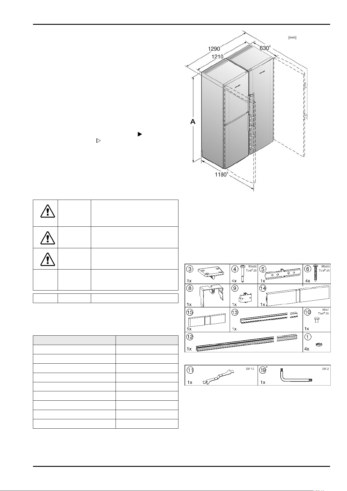
Fig. 1
x
For appliances supplied with wall spacers, the measurement
increases by 35 mm.
3 Side-by-side assembly
Install the freezer or the appliance with freezer compartment on
the left as viewed from the front. These appliances have a sidewall heating on the right-hand side to prevent the formation of
condensation.
All the assembly components are supplied with the appliance.
Note identifies useful information and tips.
2 External dimensions of the appliance
Appliance designation Height A (mm)
SBS(es) 6352 1664
SBSes 7155 1841
SBSes 7165 1841
SBS(esf) 7212 1841
SBS(es) 7252 1841
SBS(es) 7253 1841
SBS 7262 1841
SBSes 7263 1841
SBSes 7353 1841
Fig. 2
Fig. 3
Ensure that the following tools are to hand:
Spirit level
q
Power screwdriver
q
Screwdriver Torx® 25
q
Open-ended spanner size 10 (included in supply package)
q
Allen key size 2 (included in supply package)*
q
Information for moving the combined appliance:
2
Page 3

Side-by-side assembly
Before assembling the appliances, site them as closely as
q
possible to the final position.
When moving the appliances, always take hold of them at
q
the outer front corners. On no account should you push with
your knee against the side walls or door.
The combined appliance is easiest to shift diagonally by
q
moving the left and right corner alternately.
Once the combined appliance is exactly in front of the aperture, push it straight in.
If the combined appliance
q
has to be pulled out of the
aperture again, take hold of
it in the lower third area and
pull it straight forwards.
NOTICE
Risk of damage when moving the combined SBS appliance!
The combined SBS appliance is heavy once assembled. The
appliance may be dented by improper movement.
Observe the information given on moving the appliance (see
u
above).
Remove all protective film from the outside of the housing.
u
On the front of the appliance:
Move the joining plate sideways so that the centre bar of the
u
plate lies on the side wall of the appliance. Tighten the
screws.
Now screw the joining plate to the other appliance. As you
u
do this, shift the appliances together or apart slightly as
necessary.
Fig. 6
If the appliance is fitted with the pre-mounted screw
u
Fig. 6 (7)
The joining plate automatically aligns the depth of the appliances. If one appliance is further forward than the other, start
with that appliance. Otherwise start with the appliance on the
left.
Fix the joining plate
u
two screws
Move the joining plate sideways so that the centre bar of the
u
plate lies on the side wall of the appliance. Tighten the
screws.
Now screw the joining plate to the other appliance. As you
u
do this, shift the appliances together or apart slightly as
necessary.
On the rear of the appliance:
: Undo the screw.
Fig. 6 (5)
Fig. 6 (6)
.
loosely to one appliance with
Fig. 4
If necessary, completely retract the height-adjustable feet
u
Fig. 4 (A)
touching the floor.
Place the caps
u
able feet.
Push both appliances together up to approx. 10 mm apart
u
so that they stand flush at the front.
at the front of both appliances so that they are not
Fig. 4 (1)
onto the four front height-adjust-
Fig. 5
Unclip and remove the covers
u
The joining plate automatically aligns the height of the appliances. If one appliance is slightly higher than the other, start
with that appliance.
Put the joining plate
u
one appliance with two screws
Fig. 5 (3)
Fig. 5 (2)
in place and fix it loosely to
Fig. 5 (4)
.
.
Insert the joining clamp
u
side walls.
Insert the joining angle
u
bottom.
If the joining angle is too loose, fix it with a screw
u
Note
To avoid vibration noise, ensure neither the clamps nor the
u
screws are in contact with the tubes on the rear of the appliance!
On the front of the appliance:
Fig. 7 (8)
Fig. 7 (9)
at the top of the centre
into the recess at the
Fig. 7 (10)
Fig. 7
.
Fig. 8
3
Page 4

Side-by-side assembly
NOTICE
Risk of damage to the castor bases!
When aligning the appliance by the back adjustable feet, do
u
not use a cordless screwdriver, as this will either damage
the height adjustment mechanism or possibly loosen the
adjusting rod. Adjust the feet by hand.
You can adjust the front height-adjustable feet with the openended spanner
the rear height-adjustable feet* with a Torx® 25 screwdriver.
Retract the centre height-adjustable feet
u
are not in contact with the floor.
Level the combination using the outer height-adjustable feet
u
Fig. 4 (B)
Before fitting the cover strip
together along the whole length. That makes it easier to insert
the strip into the gap. Use a soft cloth to press the strip into
place to avoid making dents in the surface. Carefully press the
strip into the gap, keeping it straight, to achieve an optimal
joint.
On the front, press the long cover strip
u
vertical gap. Make sure the strip sits on top of the joining
plate
Peel the protective film off the cover strip.*
u
Fig. 8 (11)
.
Fig. 9 (5)
included in the supply package, and
Fig. 4 (C)
so they
Fig. 9
Fig. 9 (12)
.
, press the two bars
Fig. 9 (12)
into the
Fig. 11
Fit the bottom cover
u
plate
Fig. 11 (5)
Connect the combination to the mains according to the
u
manual.
Appliances with IceMakers:
Connect the appliance to the fixed water connection
u
according to the manual.
NOTICE
Risk of damage when moving the combined SBS appliance!
The combined SBS appliance is heavy once assembled. The
appliance may be dented by improper movement.
Observe the information given on moving the appliance (see
u
above).
Carefully slide the combination into the intended position.
u
If necessary, align the height with the height-adjustable feet.
u
Lower the centre height-adjustable feet
u
touch the floor.
Then support the door: Extend the height-adjustable feet
u
Fig. 4 (A)
then turn them further by 90°.
The doors can be aligned in
height with the aid of the outer,
lower turn hinges:*
Extend the threaded pin
u
at the turn hinge until they are resting on the floor,
Fig. 12 (17)
turn at most!).
Fig. 11 (15)
and snap it in at the bottom.
a little (by one
from above onto the joining
Fig. 4 (C)
until they
Fig. 10
On the top of the appliances, press the short strip
u
Fig. 10 (13)
strip is flush with the joining plate
Clip the cover
u
control panel covers. Make sure the side edges of the cover
are flush with the control panel covers. To enable this, the
cover is expandable.
into the gap. Make sure the front edge of the
Fig. 10 (14)
Fig. 10 (3)
over the gap between the two
.
To lift the door, turn the bearing pin
u
using the open-ended spanner
supply package. In the delivery condition, the bearing pin is
completely screwed in.
Tighten the threaded pin
u
bearing pin.
Fig. 12 (17)
Fig. 13 (18)
Fig. 13 (11)
again to secure the
clockwise
included in the
Fig. 12
Fig. 13
4
 Loading...