

Page 1
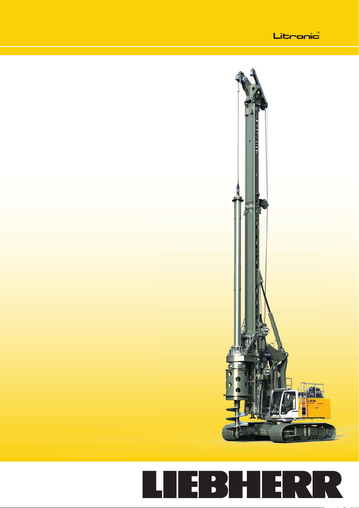
Technical data
Rotary drilling rig
L B 36 - 410
Page 2
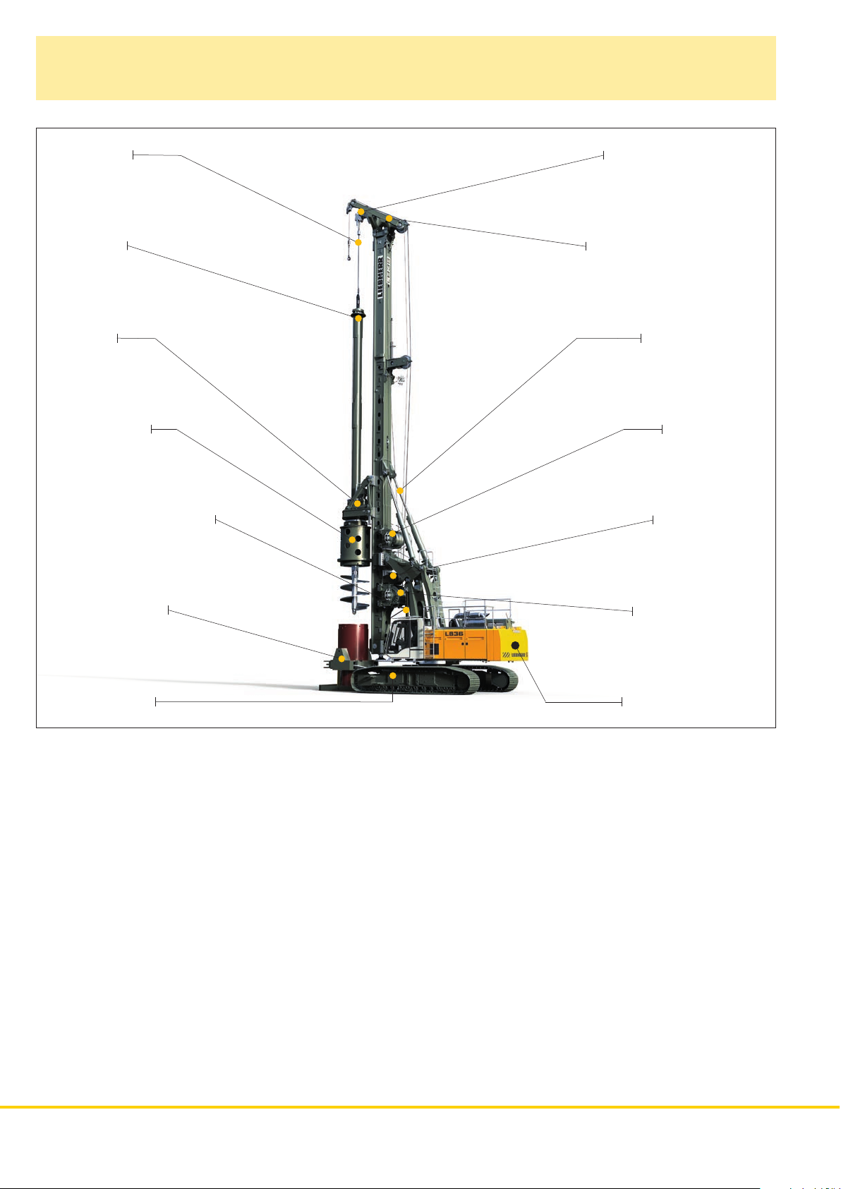
Concept and characteristics
LB 36
Kelly rope
Kelly bar
Rotary
Casing driver
Radius adjustment device
Leader top for Kelly rope
Leader top for auxiliary rope
Inclination device
Crowd winch
Auxiliary winch
Casing oscillator
Undercarriage
The robust universal machine for a wide variety of applications:
• Kelly drilling
• Auger drilling
The rigid leader absorbs high torque and is fitted with a
rope crowd system for high pull forces.
• Full displacement drilling
• Double rotary drilling
All winches are mounted on the leader, which provides
a direct view of the main winch from the operator‘s cab.
The solid undercarriage offers excellent stability and low
ground bearing pressure.
The rotary drive of the BAT series combines exceptional
torque with optimum operating comfort.
The uppercarriage with its small swing radius enables
operation in restricted space.
The powerful Liebherr diesel engine is low in emission and
economical through SCR technology.
Parallel kinematics with a large working area allow to fold
back the leader.
Kelly winch 300 kN
Counterweight 20.6 t
2 LB 36
Page 3
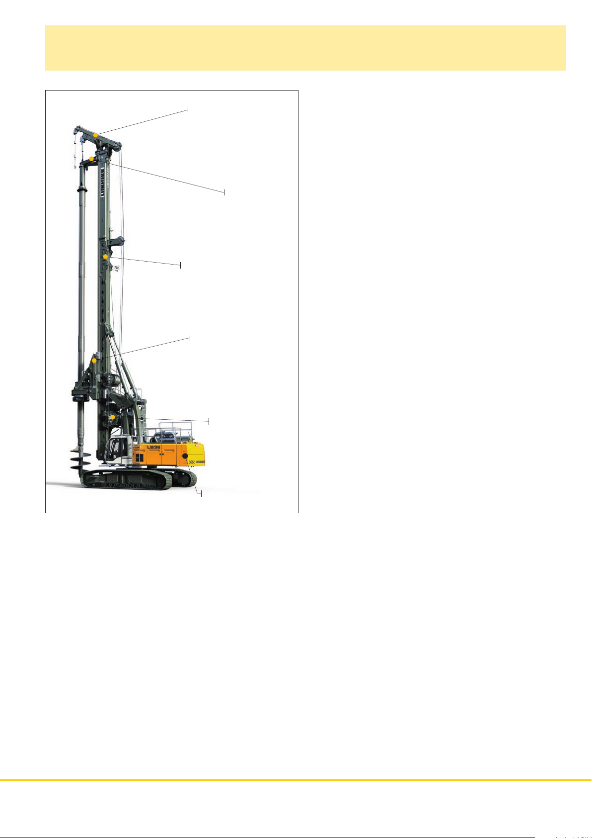
Concept and characteristics
LB 36 with optional equipment
Leader top for Kelly rope
(for extended drilling
axis - 17 00 mm )
Kelly bar guide
Leader extension 1120 mm
Adapter for extension of
drilling axis (1700 mm)
Kelly winch 400 kN
Counterweight 22.4 t
The Litronic control with assistance systems supports the
operator:
• Cruise Control for the drilling process
• Joystick control for all machine functions
• Automatic shake-off function for working tools
• Leader inclination memory etc.
Liebherr Kelly bars feature strongly overlapping elements
resulting in less wear.
Precise and robust Liebherr casings and drilling tools
provide excellent drilling performance.
Sophisticated solutions provide safe operation and maintenance of the machine.
• Cab design for optimum visibility
• Acoustic and optic warning
• Walkways on the uppercarriage
• Safety rails on top of the uppercarriage
• Rear and side view cameras etc.
LB 36 3
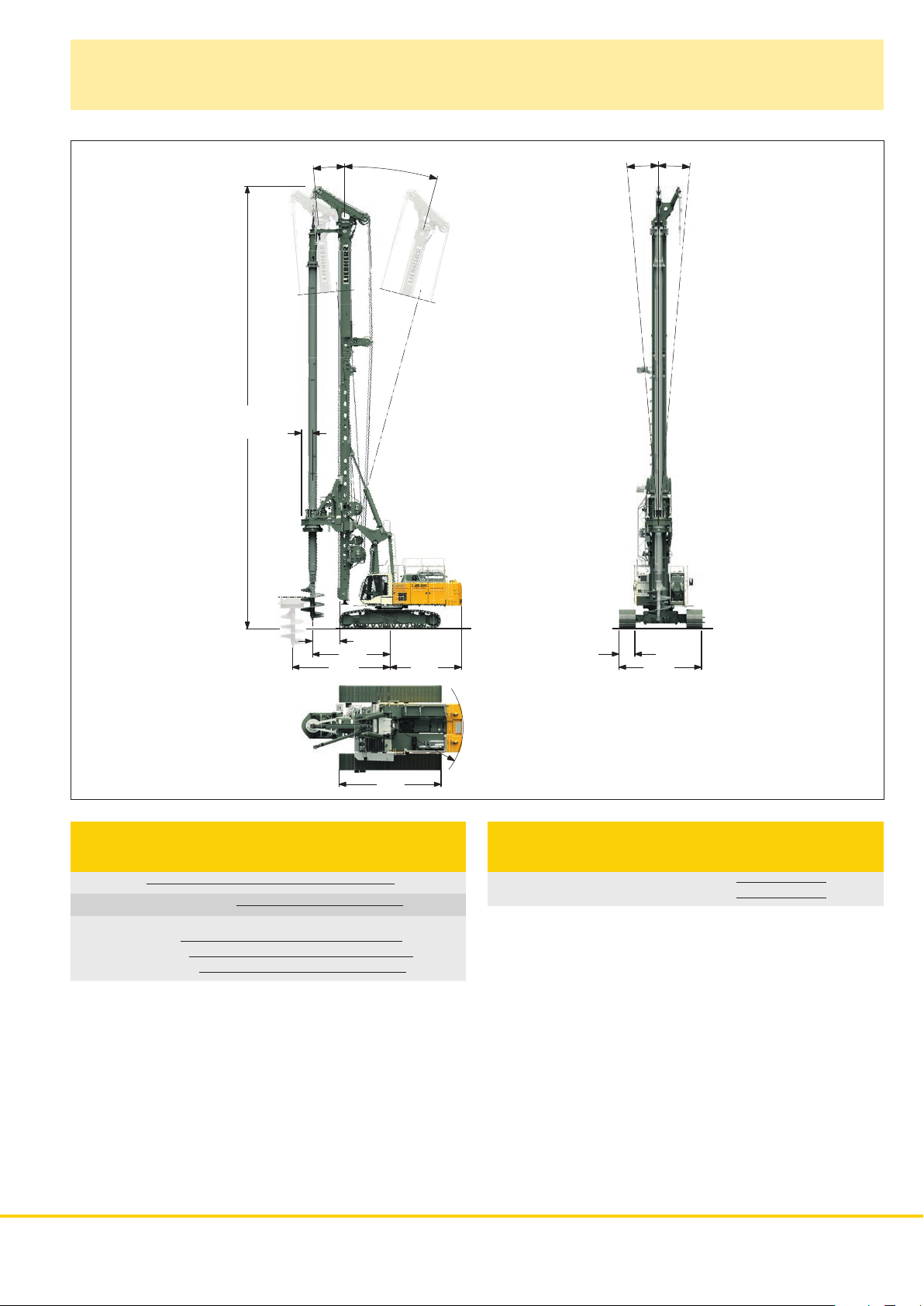
Page 4
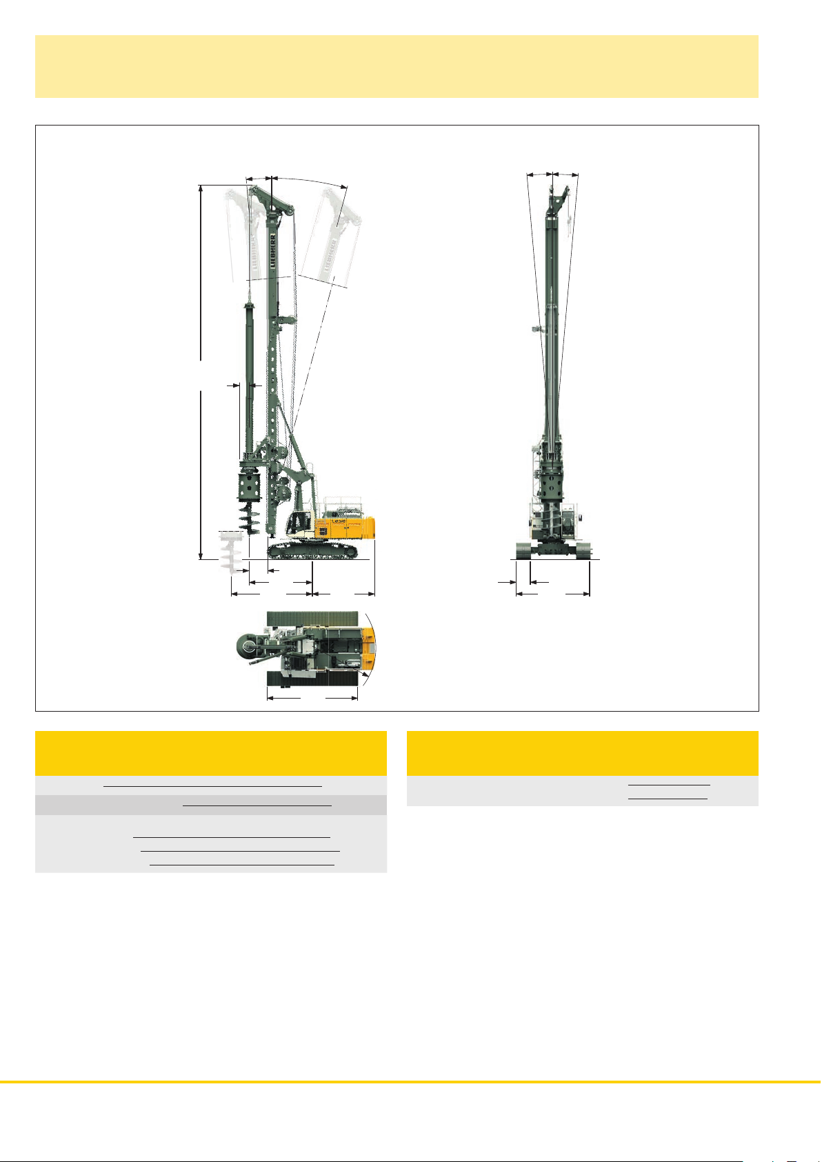
Dimensions
Basic machine LB 36
690
26200
5°
5°
15°
5°
1300
4412
5662 4370
6385
Technical data
LB 36
Total height 26.20 m
Max. pull, leader on ground
Continuous rig inclination adjustment
Lateral inclination
Forward inclination 5°
Backward inclination 15°
400 kN
± 5°
1000
5150
R 4435
Operating weight
LB 36
Total weight with 900 mm 3–web shoes 115.0 t
with 1000 mm 3–web shoes 115.7 t
The operating weight includes the basic machine LB 36 (with
rotary and Kelly bar MD 36/3/30) and 20.6 t counterweight, without
equipment for casing oscillator.
4 LB 36
Page 5
Dimensions
Basic machine LB 36 with optional equipment
690
27545
5°
15°
5°
5°
1700
4812
6062 4475
6385
Technical data
LB 36 with optional equipment
Total height 27.55 m
Max. pull, leader on ground
Continuous rig inclination adjustment
Lateral inclination
Forward inclination 5°
Backward inclination 15°
400 kN
± 5°
1000
5150
R 4540
Operating weight
LB 36 with optional equipment
Total weight with 900 mm 3–web shoes 120.5 t
with 1000 mm 3–web shoes 121.2 t
The operating weight includes the basic machine LB 36 (with
rotary and Kelly bar MD 36/3/30) and 22.4 t counterweight, without
equipment for casing oscillator.
LB 36 5
Page 6

Transport dimensions and weights
The fi gures in this brochure may include options which are not within the standard scope of supply of the machine.
25183 (*26758)
1375
6650
6383 12150 (*13725)
1000
3000
3600
3710
385
Transport standard
includes the basic machine (ready for operation) with leader, without
working tools (such as rotary, Kelly bar etc.) and without counterweight.
20485 (*21605)
6650
6383
7452 (*8572)
Transport option leader folded
includes the basic machine (ready for operation) with leader, without
working tools (such as rotary, Kelly bar etc.) and without counterweight.
25183 (*26758)
Dimensions and weights
Length 25 .18 m
Weight complete without counterweight
1375
1000
(*80.3) 78.6 t
3220
3600
3710
385
Dimensions and weights
Length 20.48 m
Weight complete without counterweight
(*80.7) 79.0 t
3000
3386
7524
4640 13019 (*14594)
Transport with optional equipment
includes the basic machine (ready for operation) with leader, without
working tools (such as rotary, Kelly bar etc.), without crawlers and
without counterweight.
25183 (*26758)
2572 11026
Transport leader
includes the leader without working tools (such as rotary,
Kelly bar etc.).
*) Rigs with optional equipment
3100
3565
Dimensions and weights
Length 26.30 m
Weight complete without counterweight
(*61.7) 59.9 t
2810
2430
Weights
Weight complete (*29.1) 27. 3 t
Lower part of the leader
Upper part of the leader with leader top
1.8 t
(*4.8) 4.6 t
895
6 LB 36
Page 7

Transport dimensions and weights
8290
1375
6383
8068
Transport basic machine
ready for operation, without counterweight.
Transport weight without self-assembly system
2515
3000
1000
3600
51.2 t
3385
385
Counterweight I Counterweight I
3710
3000
Counterweight II Counterweight II
3000
Counterweight
(standard)
Counterweight I 10.2 t
Counterweight II
665
170
2x 5.2 t
1565
3000
1565
3000
Counterweight
(
optional equipment)
Counterweight I 2x 6.0 t
Counterweight II
1620
775
1565
170
2x 5.2 t
1300
2120
Rotary
LB 36
Transport weight
BAT 410
8920
4640
1770
9.1 t
1700
2540
Rotary
with optional equipment
Transport weight
BAT 410
3000
3040
1770
11.1 t
3390
894
6383
1220
1000
Transport basic machine
ready for operation, without crawlers and without counterweight.
Transport weight
Weights can vary with the nal con guration of the machine.
32.6 t
Crawlers
Crawler left 10 .1 t
Crawler right
10 .1 t
LB 36 7
Page 8

Rotary BAT 410 with shock absorber
Gearbox frame
Drive motors
Kelly bar
Shock absorber
Gearbox
Cardan joint
Casing driver
Rotary BAT 410
Automatic gearbox for best operating comfort
• No stopping required to change gears
• No interruption of the drilling process
• Automatic torque adjustment
• Continuous optimization of speed
• Four electronically adjustable speed ranges
Highest availability through easy set-up
• No mechanical shift gearbox
• Higher availability thanks to less moving parts
• Less maintenance required
• No pressure lubrication necessary
• No interferences through defective lubrication pump
• Simplified hydraulics
• Lower risk of hydraulics leakages
Flexibility through modular design
• Exchangeable drive adapters for use of other Kelly bars
• Exchangeable cardan joint for other casing drivers
• Quickly exchangeable equipment for other methods of operation
8 LB 36
450
400
350
300
250
200
kNm
150
100
50
0
0 10 20 30 40 50
BAT 410
rpm
Nominal
450
400
350
300
250
200
kNm
150
100
50
0
0 10 20 30 40 50
BAT 410
rpm
Effective
Page 9

54
A
1900
X
Kelly drilling
A
2
3
bar
0100200300400
15
2
1900
bar
X
0200300400
100
83 mm/U
Display for Kelly drilling
Technical data
Rotary drive - torque 410 kNm
Rotary drive - speed
37 rpm
Kelly bars
A X Drilling
(mm) (mm) (m) (t) (mm)
MD 36/3/30 119 0 0 9800 28.0 7.6 470
MD 36/3/36 139 00 780 0 34.0 8.8 470
MD 36/4/42 12950 8700 40.0 10.3 470
MD 36/4/48 14 45 0 7200 46.0 11.5 470
Performance data
Max. drilling diameter* 2300 mm uncased
Max. drilling diameter* 2000 mm cased
MD 36/4/54 159 50 5700 52.0 12.7 470
MD 36/4/60 174 50 4200 58.0 13.9 470
MD 36/4/66 189 50 2700 64.0 15.1 470
*) Other drilling diameters available on request Other Kelly bars available on request
When using a casing oscillator, value X has to be reduced
by 1600 mm.
-63.9
200
-24.3
kN
m
depth
1.23
m/min
-5.56m
kN
KELLY
188.2
0.00
m/min
-24.25m
300
200
100
0
MODE
kN
°0.1
bar
rpm
2200
400
1900
300
1600
200
1300
100
1000
700
0
Weight Kelly Ø
10
:
°0.0
Nm%
100
80
60
40
20
0
LB 36 9
Page 10

54
bar
bar
Kelly drilling
with optional equipment
A
1900
X
Technical data
Rotary drive - torque 410 kNm
Rotary drive - speed
37 rpm
Performance data
Max. drilling diameter* 3000 mm uncased
Max. drilling diameter* 2500 mm cased
*) Other drilling diameters available on request
Other Kelly bars available on request
When using a casing oscillator, value X has to be reduced
by 1600 mm.
2
3
1.23
m/min
-5.56m
-63.9
kN
KELLY
0.00
188.2
m/min
MODE
300
200
100
0
kN
°0.1
bar
rpm
2200
400
1900
300
1600
200
1300
100
1000
700
0
0100200300400
15
2
0200300400
100
83 mm/U
200
-24.3
kN
m
-24.25m
Display for Kelly drilling
Kelly bars
A X Drilling
depth
(mm) (mm) (m) (t) (mm)
MD 36/3/30 11900 11100 28.0 7.6 470
MD 36/3/36 13900 9100 34.0 8.8 470
MD 36/4/42 12950 10100 40.0 10.3 470
MD 36/4/48 14450 8600 46.0 11.5 470
MD 36/4/54 15950 7100 52.0 12.7 470
MD 36/4/60 17450 5600 58.0 13.9 470
MD 36/4/66 18950 4100 64.0 15.1 470
MD 36/4/72 20450 2600 70.0 16.3 470
MD 28/5/78 18250 4900 76.0 14.0 508
MD 28/5/84 19450 3700 82.0 15.0 508
MD 28/5/90 20650 2400 88.0 16.8 508
Weight Kelly Ø
10
:
°0.0
Nm%
100
80
60
40
20
0
LB 36
10
Page 11

30
Double rotary drilling
Typ DBA 200
Technical data
Rotary drive I - torque 1
Rotary drive I - speed 1
Rotary drive I - torque
Rotary drive I - speed 2
Rotary drive II - torque
Rotary drive II - speed 1
Rotary drive II - torque
Rotary drive II - speed 2
Max. drilling diameter*
Max. drilling depth**
Max. pull force
*) Other drilling diameters available on request
**) Other drilling depths available on request
st
gear 195 kNm
st
gear 9 rpm
nd
2
gear 97 kNm
nd
gear 18 rpm
st
1
gear 103 kNm
st
gear 17 rpm
nd
2
gear 51 kNm
nd
gear 34 rpm
750 mm
17. 30 m
900 kN
3
bar
bar
bar
%
0125
0.29m³
0100200300400
0100200300400
-10010203040
Display for double rotary drilling
2
3.27
m/min
-10.80m
-88.4
kN
KELLY
0.00
12.0
600
400
200
0
m/min
bar
400
300
200
100
kN
0
15
9.7
200
kN
11:
°0.0
°0.0
rpm
Nm%
2200
100
1900
80
1600
60
1300
40
1000
20
700
0
0.00m
MODE
LB 36 11
Page 12

Continuous fl ight auger drilling
Auger with auger guide
bar
bar
%
Display for continuous ight auger drilling
Technical data
Rotary drive - torque 410 kNm
Rotary drive - speed
37 rpm
Performance data
Drilling depth with auger cleaner* 17. 30 m
Drilling depth without auger cleaner*
Drilling depth with 8 m Kelly extension
without auger cleaner
Max. pull force (crowd winch and Kelly winch)
Max. push force (weight of rotary and auger to be added)
Max. drilling diameter**
*) Without Kelly extension
**) Other drilling diameters available on request
2
2
3
1.73
m/min
15.34 m
194.7
0125
1.44m³
0100200300400
3.1
1
-10010203040
kN
KELLY
1.73
376.3
m/min
600
400
bar
400
200
300
200
0
100
kN
0
200
kN
11:18
°0.0
°0.1
rpm
Nm
%
2200
100
1900
80
1600
60
1300
40
1000
20
700
0
15.34 m
MODE
17. 80 m
25.80 m
1000 kN
200 kN
1200 mm
12 LB 36
Page 13

18
Full displacement drilling
Full displacement tool with auger guide
bar
bar
%
Display for full displacement drilling
Technical data
Rotary drive - torque 410 kNm
Rotary drive - speed
37 rpm
Performance data
Drilling depth* 17. 80 m
Drilling depth with 8 m Kelly extension
Max. pull force (crowd winch and Kelly winch)
Max. push force (weight of rotary and
drilling tool to be added)
Max. drilling diameter**
*) Without Kelly extension
**) Other drilling diameters available on request
2
2
3
1.73
m/min
15.34 m
194.7
0125
1.44m³
0100200300400
3.1
1
-10010203040
kN
KELLY
1.73
376.3
m/min
600
400
bar
400
200
300
200
0
100
kN
0
200
kN
11:
°0.0
°0.1
rpm
Nm
%
2200
100
1900
80
1600
60
1300
40
1000
20
700
0
15.34 m
MODE
25.80 m
1000 kN
200 kN
600 mm
LB 36 13
Page 14

Technical description
Engine
Power rating according to ISO 9249, 390 kW (523 hp) at 1900 rpm
Engine type Liebherr D 856 A7 SCR
Fuel tank 700 l capacity with continuous level
indicator and reserve warning
Engine complies with NRMM exhaust certication EPA/CARB Tier 4i
and 97/68 EC Stage III B.
Hydraulic system
The main pumps are operated by a distributor gearbox. Axial piston
displacement pumps work in open circuits supplying oil only when
needed (ow control on demand).
The hydraulic pressure peaks are absorbed by the integrated
automatic pressure compensation, which relieves the pump and
saves fuel.
Pumps for working tools 2x 350 l/min
Separate pump for kinematics 180 l/min
Hydraulic oil tank 800 l
Max. working pressure 350 bar
The cleaning of the hydraulic oils occurs via an electronically
monitored pressure and return filter.
Any clogging is shown on the display in the cab.
The use of synthetic environmentally friendly oil is also possible.
Control
The control system – developed and manufactured by Liebherr – is
designed to withstand extreme temperatures and the many heavy–
duty construction tasks for which this machine has been designed.
Complete machine operating data are displayed on a high resolution
monitor screen. A GSM/GPRS telematics module allows for remote
inquiry of machine data and operational conditions. To ensure clarity
of the information on display, different levels of data are shown in
enlarged lettering and symbols.
Control and monitoring of the sensors are also handled by this high
technology system. Error indications are automatically displayed on
the monitor in clear text. The machine is equipped with proportional
control for all movements, which can be carried out simultaneously.
Two joysticks are required for operation. Pedal control can be
changed to hand control.
Option:
PDE®: Process data recording
Kelly winch with freewheeling
Line pull ef fective (1st layer) 300 kN
Rope diameter 34 mm
Line speed 0-71 m/min
Option:
Line pull ef fective (1st layer) 400 kN
Rope diameter 38 mm
Line speed 0-59 m/min
Crawlers
Propulsion through axial piston motor, hydraulically released spring
loaded multi–disc brake, maintenance-free crawler tracks, hydraulic
chain tensioning device.
Drive speed 0 – 1.4 km/h
Track force 814 kN
Wid th of 3- we b gr ous ers 1000 mm
Transport width 3600 mm
Option:
Width of 3-web grousers 900 mm
Transport width 3500 mm
2-speed hydraulic motor for higher travel speed
Swing
Consists of triple-row roller bearing with external teeth and two
swing drives, fixed axial piston hydraulic motor, spring loaded and
hydraulically released multi–disc holding brake, planetary gearbox
and pinion. Selector for 3 speed ranges to increase swing precision.
Swing speed from 0 – 2 rpm is continuously variable.
Auxiliary winch
Line pull ef fective (1st layer) 100 kN
Rope diameter 20 mm
Line speed 0-89 m/min
Rope crowd system
Crowd force push/pull 400/400 kN
Line pull (effective) 200 kN
Rope diameter 28 mm
Travel 18.50 m
Line speed 0-70 m/min
The winches are noted for compact, easily mounted design.
Propulsion is via a maintenance-free planetary gearbox in oil bath.
Load support by the hydraulic system; additional safety factor by
a spring–loaded, multi–disc holding brake. All line pull values are
effective values. The efficiency factor of approx. 25% has already
been deducted.
Noise emission
Noise emissions correspond with 2000/14/EC directive on noise
emission by equipment used outdoors.
14 LB 36
Page 15

Process data recording system - PDE
®
(additional equipment)
The Liebherr process data recording system PDE® constantly records the relevant process data
during the working process.
59% 7
pile number 12A/23
pile number
ø 60 cm
10%
10%
3.5 m
3.5 m
3.65 m
3.61m
4.0 m
4.0 m
4.5 m
4.5 m
5.0 m
5.0 m
12A/23
CompactFlash
memory card
5.5 m
5.5 m
70
60 50 40 30 0 5 10 30 bar
ABC
ABC
PDE® colour monitor
for visualization of the PDE® data
in the operator's cab
Standard
Optional
3040506070
0 5 10 30 bar
PC provided
by the customer
Printer
Process data report
software PDR
®
PDE
External sensors
Depending on the application the recorded and processed data are displayed on the PDE® touchscreen in the operator‘s cab, e.g. in the form
of an online cast-in-place pile.
At the same time the PDE
start and stop recordings. A recording of every start-stop cycle carried out in the PDE
®
is operated using this touchscreen. The operator can enter various details (e.g. jobsite name, pile number, etc.) and
®
is established on a CompactFlash memor y card.
The PDE® can be confi gured in a number of ways, e.g. for the connection of external sensors, for the generation of a simple protocol as graphic
le and/or for a printout directly in the operator‘s cab.
Process data reporting - PDR (additional equipment)
Comprehensive data evaluation and generation of reports on a PC is possible using the
software PDR.
Recordings management - The recordings generated by the PDE
in PDR. The data can be impor ted directly from the CompactFlash card or via the Liebherr telematics
system LiDAT. Certain recordings, e.g. for a particular day or jobsite, can be found using lter functions.
Viewing data - The data in each record is displayed tabularly. Combining several recordings provides
results, for example, regarding the total concrete consumption or the average depth. Furthermore, a diagram
editor is available for quick analysis.
Generating reports - A vital element of PDR is the repor t generator, which allows for the generation of
individual reports. These can be printed out directly or stored as pdf les. In the process the size, colour, line
thickness or even the desired logo can be confi gured. Moreover, the repor ts can be displayed in different
languages, e.g. in English and in the national language.
®
system can be imported and managed
CFA Drilling
job site:
machine ID:
start date:
start time:
stop time:
duration:
motorway
1155xx
05.11.2008
12:16:48
12:48:48
00:32:00
pile number:
maximum depth:
total concrete vol.:
concrete volume pile:
overconsumption:
maximum incline:
E02
2227 cm
15,123 m³
14,531 m³
29,8 %
0,4 °
LB 36 15
Page 16

Liebherr-Werk Nenzing GmbH
Dr. Hans Liebherr Str. 1, 6710 Nenzing/Austria
Tel.: +43 50809 41–473, Fax: +43 50809 41–499
crawler.crane@liebherr.com, www.liebherr.com
facebook.com/LiebherrConstruction
LB 36 – 10505378 – 03/2013 Subject to change without notice.
 Loading...