


 LG
LG
2018 UHD 720p LCD TV Training Materials
32LK610BPUA WebOS 4.0 FHD TV POWER SUPPLY TESTING
Using a Simple 3V Jig or
Smart TV Test Jig and Multi-Gender Board
Published October 09th, 2018

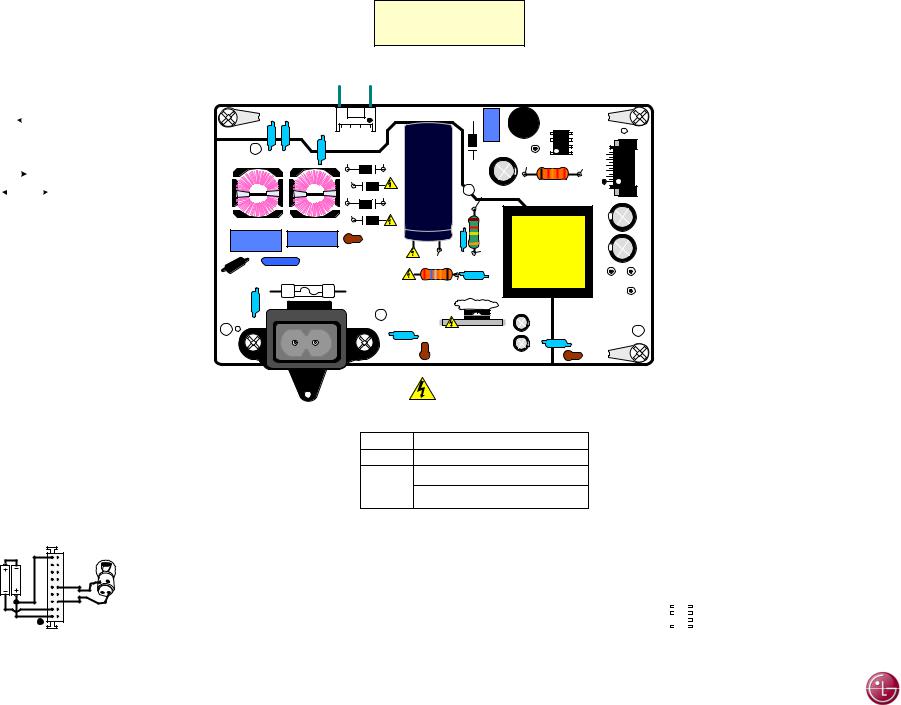
Power Supply (SMPS) Board Layout (EAY64548901)
32LK610BPUA (2018) Power Supply Testing
To Backlights
P801
To Main
Board P2300
P201
SK100
AC In
October 2018 |
Page 01 |
|
 LG
LG
32LK610BPUA SMPS (Power Supply) Drawing
P801 To Panel Backlight Power pin 7.
P801 Pin 1 goes to Backlight Driver
Q801 (Back of SMPS)
LED- (95.8V) 50%
LED+ (118.5V) 50%
P801 "SMPS Board" To "LED Backlights"
PIN |
|
LABEL |
RUN |
Diode |
|||||||
1 |
|
|
|
|
|
|
|
LED- |
110.4V~89V |
OL |
|
|
|
|
|
|
|
||||||
3 |
|
|
|
|
|
|
|
N/C |
n/c |
n/c |
|
5 |
|
|
|
|
|
|
|
N/C |
n/c |
n/c |
|
7 |
|
|
|
|
|
|
|
LED+ |
134.8V~113.2V |
OL |
|
|
|
|
|
|
|
||||||
|
|
|
|
|
|
|
|
|
|
|
|
In |
|
|
Out |
|
|
Dim to Bright |
|
||||
|
|
|
|
||||||||
AC 1st applied 168V (30sec) then fall to 76V During Stand-By LED+ will fluctuate 76V Main Board Disconnected: 69V
Backlight Setting Dim 0% to Bright 100% Pins 2-6 are not connection.
Direct Lit Backlights (8 LEDs on 1 Array Strip)
SMPS TEST: Forcing SMPS On.
This test requires simple 3V jig.
See below or Multi-Gender Board, use Port P16 (12pin), See Article 9627.
SMPS
P/N: EAY64548901
|
|
|
|
|
|
To Backlight LEDs |
|
|
|
|
|
|
|
P204 |
7.83V (13.20V) |
||
|
|
|
|
|
|
|
|
|
|
|
|
|
P203 |
7.83V (13.20V) |
|||
|
|
|
|
|
78V (116V) |
(91V) |
|
|
|
|
|
|
|
P202 |
7.83V (13.20V) |
||
|
|
|
|
|
|
|
|
|
|
|
|
P802 |
60.42V (90V) |
||||
|
|
|
|
|
|
LED+ |
LED- |
|
|
|
|
|
|
|
|||
|
|
CY101 |
|
CY103 |
|
|
|
C806 |
|
|
|
|
P201 |
||||
|
|
|
|
|
|
D802 |
L801 |
IC801 |
|||||||||
|
|
|
|
|
|
|
|
|
|
|
|
||||||
|
|
|
|
|
|
CY104 |
|
|
|
|
|
|
|
||||
|
|
|
|
|
|
P801 |
|
|
|
|
P802 |
|
|
0V |
|
||
|
|
|
|
|
|
69V |
168V (159V) |
|
|
|
|
|
Gnd |
|
|
||
|
|
|
|
|
|
C601 |
78V |
|
(0.15V) |
|
|||||||
|
|
|
|
|
|
|
D104 |
C205 |
|
||||||||
|
|
|
|
|
|
|
|
(116V) |
|
|
|
|
|
||||
|
|
|
|
|
|
69V |
D103 |
|
|
|
|
|
|
||||
|
|
|
|
|
|
460V |
|
|
|
|
|
R816 |
|
|
|||
|
|
|
|
|
|
69V |
168V (159V) |
|
171V (288V) |
|
|
|
|||||
|
|
|
|
|
|
120uF |
|
SECONDARY |
|
||||||||
|
|
|
|
|
|
69V |
D102 |
|
|
|
|
|
|
|
|
|
|
|
|
|
|
|
|
|
- + |
|
|
|
|
|
|
|
|
C203 |
|
|
|
|
LF101 |
|
LF102 |
|
|
|
|
|
|
|
|
|
|||
|
|
|
|
D101 |
|
|
R112 |
|
|
|
|
|
|||||
|
|
|
CX101 |
CX102 |
|
|
|
|
|
|
|
||||||
|
|
|
|
|
|
|
168V |
|
T101 |
|
C201 |
||||||
|
|
|
|
|
|
LB112 |
|
|
|
|
|
||||||
|
|
|
|
|
|
F100 |
|
168V (159V) |
C107 |
(159V) |
|
|
|
||||
|
1 |
|
VA100 |
|
|
C108 |
|
|
|
|
|
P204 |
P203 |
||||
|
1 |
|
5A / 250V |
|
|
|
|
|
|
|
|
|
|||||
H |
0 |
|
|
|
|
R113 |
(0V) |
|
|
|
|
|
|
|
P202 |
||
|
|
|
|
|
|
|
|
|
|
|
|
|
|||||
T |
|
|
|
|
|
|
|
|
|
|
|
|
|
|
|||
CY102 |
|
|
|
PRIMARY |
Can’t Read |
|
|
|
|
||||||||
|
|
|
|
|
|
|
|
|
|
|
|
|
|
||||
|
|
|
|
|
|
|
CY111 |
|
|
|
|
C106 |
Chassis Gnd |
||||
|
|
|
|
|
|
|
Q101 |
|
C105 |
CY111 |
|
||||||
Using 3V Simple Jig: Remove AC Power. Disconnect P2300 on Main Board.
Test 1: Using a 3V jig, Jump 3V to pin 1 (PWR_ON). Apply AC Power. (No Backlights in Test 1)
(Pins 4-8) rises to 13.13V. Backlight Power LED+ 114.8V. LED95.6V. PDIM will be 3.42V. Remove AC Power.
Test 2: Using a 3V jig, Jump 3V to pin 11 (DRV_ON). Place a 12V Light Bulb on 13.2V to Gnd.
Apply AC Power. All Voltages should be produced. (13.2V) 12.95V to Main and
“LED+” 119.2V to the Backlights), “LED-“ 94.3V.
This will also force the Backlights to come on. PDIM will be 3.77V
SK100
AC
LB110 |
LB113 |
|
Hot Gnd
(Shock Hazard)
VOLTAGE LABEL
MODEL LGP32D-17F1
INPUT AC100V~240Vac 50/60Hz. 1.5A
13.2V = 1.8A
OUTPUT
31V – 660mA
Test 2 |
P201 |
|
|
11 |
12 |
|
|
AA 2 |
|
10 |
Solder 1157 |
(3V) |
|
|
|
3 |
6 |
Solder |
|
|
|
|
|
Test 1 |
1 |
2 |
|
Test Set Up |
|
||
Note:
P201 still inserted. P2300 removed. Use P2300 side to insert needles from the Jig.
Note: STBY 7.83V (Pins 4-8) Must be present when AC is applied before beginning test which indicates Standby voltage is OK.
Special Note:
The 13.2V Line “Must” be loaded using a 12V light Bulb when using the 3V Simple Jig).
3V SIMPLE JIG: Made from 2 (AA) batteries. Jump + to – on one side.
On the other side, solder two red wires (needle tipped) to the + and one black wire (needle tipped) to the – side.
See Article 8979
Note: For Ground you can use Panel Back.
32LK610BPUA (2018) Power Supply Testing
Note: The Smart Test Jig and Multi-Gender Board “Can” be used in this model for testing. Use Port P16. 13.2V Line does not have to be loaded in this case,
Jig Switch set to 24V / LCD Power (See Article 9627).
P201 "SMPS Board" To P2300 "MAIN Board" |
|
|
|||||
|
|
|
|
|
|
|
MAIN |
PIN |
LABEL |
STBY |
|
RUN |
|
Diode |
|
|
|
|
|
|
|
|
12 |
(3) 12 |
P-DIM |
0V |
|
*0.16V-3.18V |
|
OL |
|
(2) 11 |
MS (Drv_On) |
0V |
|
1.97V |
|
OL |
11 |
9-10 |
Gnd |
Gnd |
|
Gnd |
|
Gnd |
9-10 |
4-8 |
13.2V |
7.83V |
|
13.10V |
|
OL |
8-4 |
3 |
Gnd |
Gnd |
|
Gnd |
|
Gnd |
3 |
2 |
N/C |
n/c |
|
n/c |
|
n/c |
2 |
(1) 1 |
PWR_ON |
0V |
|
3.35V |
|
1.20V |
1 |
|
|
|
*Dim to Bright |
|
|
||
Voltages below for Backlight Power (LED+) are with Main disconnected and using Simple 3V Jig to supply turn-on commands on-at-a-time.
(Special Note: 13.2V Line “Must” be loaded using a 12V light Bulb when using the 3V Simple Jig).
(1)PWR-On Pin 1: Turns on 13.2V to the Main. No backlights at this time. Backlight Power is 114.6V.
(2)MS (DRV_On) Pin 11: Turns on the Backlights. Backlight power goes to 119.3V.
Voltages given below for PDIM are with Main connected and receiving normal Digital Antenna Signal.
(3) PDIM Pin 12: Will vary according to incoming video IRE level and OSD Backlight setting Output from the Video Processor. And the Backlight settings in the Customer’s Menu 0% TO 100%. It is then routed out P1001 to P201 and sent to the LED Driver IC on the Back of the SMPS. The Range is: Dim 0.17V ~ Bright 3.28V. (1.76V at 50%) PDIM is actually a 3.44V p/p pulse (PWM Control).
|
|
|
Pin |
Run |
Pin |
Run |
IC801 |
4) |
0.86V |
5) |
3.19V |
||
|
|
|
3) |
13.1V |
6) |
Gnd |
|
|
|
||||
|
|
|
2) |
n/c |
7) |
1.95V |
|
|
|
1) |
89V |
8) |
Gnd |
October 2018 |
Page 02 |
LG |
|
 Loading...