


 Loading...
<![endif]>ENGLISH
OWNER’S MANUAL
PLASMA TV
Please read this manual carefully before operating your set and retain it for future reference.
www.lg.com
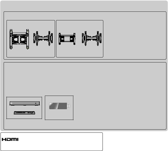
Separate purchase
Wall Mounting Bracket
AW-50PG60MS AW-50PG60M AW-60PG60MS AW-60PG60M
or |
or |
(50PK7***, 50PK9***) |
(60PK7***, 60PK9***) |
Optional extras can be changed or modified for quality improvement without any notification. Contact your dealer for buying these items.
This device only works with compatible LG Plasma TV.
Wireless LAN for
Broadband/
Wireless Media Box |
DLNAAdaptor |
AV1 |
AV2 |
COM1 |
COM2 |
RGB |
HDMI 1 |
HDMI 2 |
HDMI 3 |
HDMI 4 |
WIRELESS |
|
|
|
|
|
|
WIRELESS |
|
OUT |
|
|
|
|
|
|
|
CONTROL |
|
|
|
(Except for 50/60PK950)
HDMI, the HDMI logo and High-Definition Multimedia Interface are trademarks or registered trademarks of HDMI Licensing LLC.

CONTENTS
PREPARATION |
|
Accessories...................................................... |
A-1 |
Front Panel Controls........................................ |
A-2 |
Back Panel Information................................... |
A-3 |
Stand Installation............................................. |
A-4 |
Back Cover for Wire Arrangement................... |
A-5 |
How to remove the Cable Management Clip.. |
A-5 |
Not using the Desk-type Stand ...................... |
A-6 |
Swivel Stand.................................................... |
A-6 |
Careful Installation Advice .............................. |
A-6 |
Desktop Pedestal Installation.......................... |
A-7 |
Wall Mount: Horizontal Installation.................. |
A-7 |
Remote Control Key Functions....................... |
A-8 |
EXTERNAL EQUIPMENT SETUP |
|
Antenna Connection............................................ |
1 |
Connecting with a Component cable.................. |
2 |
Connecting with an HDMI cable.......................... |
3 |
Connecting with an HDMI to DVI cable............... |
4 |
USB Setup........................................................... |
4 |
Connecting with an RF Cable.............................. |
5 |
Connecting with an RCA cable............................ |
5 |
Connecting with a D-sub 15 pin cable................ |
6 |
Digital audio out Setup........................................ |
6 |
External Equipment Wireless Connection........... |
7 |
Supported Display Resolution............................. |
8 |
Screen Setup for PC mode................................. |
9 |
Network Setup................................................... |
13 |
WATCHINGTV/PROGRAMMECONTROL |
|
Turning on the TV.............................................. |
23 |
Initializing Setup ................................................ |
23 |
Programme Selection........................................ |
23 |
Volume Adjustment............................................ |
23 |
Quick Menu........................................................ |
24 |
On Screen Menus Selection and Adjustment... |
25 |
Auto Programme Tuning ................................... |
27 |
Manual Programme Tuning............................... |
28 |
Programme Edit ................................................ |
31 |
Software Update................................................ |
35 |
Picture/Sound Test............................................. |
37 |
Diagnostics........................................................ |
38 |
Product/Service Information.............................. |
39 |
Network Test...................................................... |
39 |
Simple Manual................................................... |
40 |
Selecting the Programme List........................... |
41 |
Input List............................................................ |
43 |
Input Label......................................................... |
44 |
SIMPLINK.......................................................... |
45 |
AV Mode............................................................ |
48 |
Initializing(Reset to original factory settings)..... |
49 |
NETCAST |
|
Legal Notice....................................................... |
50 |
Netcast Menu..................................................... |
52 |
Bigpond.............................................................. |
53 |
Movie Online...................................................... |
56 |
Weather info....................................................... |
58 |
Photo Album...................................................... |
59 |
TO USE A USB OR PC DEVICE |
|
When connecting a USB device........................ |
60 |
DLNA.................................................................. |
62 |
Movie List........................................................... |
66 |
Photo List........................................................... |
76 |
Music List........................................................... |
84 |
DivX Registration Code..................................... |
90 |
Deactivation....................................................... |
91 |
GAME |
|
Game................................................................. |
92 |
EPG(ELECTRONIC PROGRAMME |
|
GUIDE)(IN DIGITAL MODE) |
|
Switch On/Off EPG............................................ |
94 |
Select a Programme.......................................... |
94 |
Button Function in NOW/NEXT Guide Mode.... |
94 |
Button Function in 8 Day Guide Mode.............. |
95 |
Button Function in Date Change Mode............. |
95 |
Button Function in Extended Description Box... |
95 |
Button Function in Remind Setting Mode.......... |
96 |
Button Function in Schedule List Mode............. |
96 |
<![endif]>CONTENTS
I

CONTENTS
<![endif]>CONTENTS
MHEG (MULTIMEDIA AND HYPERMEDIA INFORMATION CODING EXPERT GROUP)(IN DIGITAL MODE)
Switch on MHEG .............................................. |
97 |
Select a Programme.......................................... |
97 |
Button Function in Listing Mode........................ |
98 |
Button Function in NOW/NEXT Mode............... |
98 |
PICTURE CONTROL |
|
Picture Size (Aspect Ratio) Control................... |
99 |
Picture Wizard................................................. |
101 |
Energy Saving................................................. |
102 |
Preset Picture Settings.................................... |
103 |
Manual Picture Adjustment.............................. |
105 |
Picture Improvement Technology.................... |
106 |
Expert Picture Control...................................... |
107 |
Picture Reset................................................... |
110 |
Image Sticking Minimization (ISM) Method..... |
111 |
Mode Setting.................................................... |
112 |
Demo Mode..................................................... |
113 |
SOUND & LANGUAGE CONTROL |
|
Auto Volume Leveler....................................... |
114 |
Clear Voice II................................................... |
115 |
Preset Sound Settings-Sound Mode............... |
116 |
Sound Setting Adjustment -User Mode........... |
117 |
Infinite Sound................................................... |
117 |
Balance............................................................ |
118 |
TV Speakers On/ Off Setup............................. |
119 |
DTV Audio Setting (In digital mode only)........ |
120 |
Selecting Digital Audio out............................... |
121 |
Audio Reset..................................................... |
122 |
I/II |
|
-Stereo/DualReception(Inanaloguemodeonly)...... |
123 |
- NICAM Reception (In analogue mode only)........ |
124 |
- Speaker Sound Output Selection.................. |
125 |
Country Selection............................................ |
126 |
Language Selection (In digital mode only)...... |
127 |
TIME SETTING |
|
Clock Setup..................................................... |
129 |
Auto On/Off Time Setting................................. |
130 |
Sleep Timer Setting......................................... |
131 |
PARENTAL CONTROL / RATINGS |
|
Set Password & Lock System......................... |
132 |
Block Programme............................................ |
133 |
Parental Control (In digital mode only)............ |
134 |
External Input Blocking.................................... |
135 |
Key Lock.......................................................... |
136 |
TELETEXT |
|
Switch On/Off .................................................. |
137 |
SIMPLE Text.................................................... |
137 |
TOP Text.......................................................... |
138 |
FASTEXT......................................................... |
138 |
Special Teletext Functions............................... |
139 |
DIGITAL TELETEXT |
|
Teletext within Digital Service.......................... |
140 |
Teletext in Digital Service................................ |
140 |
APPENDIX |
|
Troubleshooting............................................... |
141 |
Maintenance.................................................... |
143 |
Product Specifications .................................... |
144 |
IR Codes.......................................................... |
145 |
External Control Device Setup........................ |
146 |
Open source software notice........................... |
153 |
II
PREPARATION
PLASMA TV Models : 50/60PK7***, 50/60PK9***
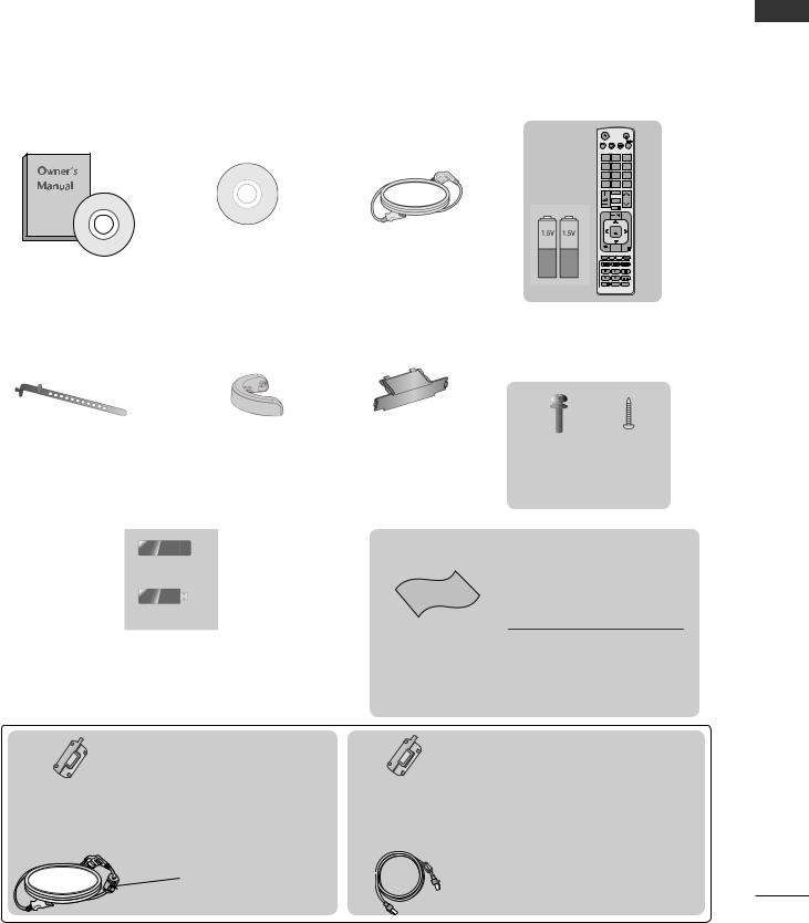
ACCESSORIES
Ensure that the following accessories are included with your TV. If an accessory is missing, please contact the dealer where you purchased the TV.
■■ Image shown may differ from your TV.
|
|
|
|
|
|
LIGHT |
|
|
|
|
|
ENERGY AV MODE INPUT |
|
||
|
|
|
|
|
|
TV/ |
|
|
|
|
|
|
|
RAD |
|
|
|
|
|
SAVING |
|
|
|
|
|
|
|
1.,;@ |
2abc |
3def |
|
|
|
|
|
4ghi |
5jkl |
6mno |
|
|
|
|
|
7pqrs 8tuv 9wxyz |
|
||
|
|
|
|
LIST |
0[ |
Q.VIEW |
|
|
|
|
|
|
MARK |
|
|
|
|
|
|
|
FAV |
|
|
|
|
|
|
|
CHAR/NUM |
|
P |
|
|
|
|
|
RATIO |
P |
A |
|
|
|
|
|
EG |
||
|
|
|
|
|
DELETE |
|
|
|
|
|
|
|
MUTE |
|
|
|
|
|
|
MENU |
|
Q.MENU |
|
|
Nero MediaHome |
Power Cord |
|
|
OK |
|
|
|
|
BACK |
GUIDE |
FREEZE |
|
||
|
|
|
|
EXIT |
|
||
Owner’s Manual |
4 Essentials CD |
|
|
INFO |
AD |
APP/* |
|
|
|
|
|
|
|||
|
|
|
Remote Control |
||||
|
|
|
Batteries (AAA) |
||||
|
x 2 |
|
|
x 4 |
|
|
x 4 |
|
|
|
|
|
|
||
|
Cable |
Protection |
|
|
|
|
|
Cable Holder |
Cover |
M4x28 |
M4x14 |
||||
Management Clip |
|
||||||
Bolts for stand assembly (Only 50PK7***, 50PK9***)
Wireless LAN for Broadband /DLNAAdaptor
(Only for 50/60PK950)
Ferrite Core
(This item is not included for all models.)
Ferrite core can be used to reduce the electromagnetic wave when connecting the power plug.
The closer the location of the ferrite core to the power plug, the better it is.
Install the power plug closely.
This item is not included for all models.
Polishing Cloth
Polishing cloth for use on the screen.
* Lightly wipe any stains or fingerprints on the surface of the TV with the polishing cloth.
Do not use excessive force. This may cause scratching or discolouration.
Ferrite Core
(This item is not included for all models.)
Ferrite core can be used to reduce the electromagnetic wave when connecting the LAN cable.
Place the ferrite core far from TV and wind the LAN cable in the ferrite core once.
<![endif]>PREPARATION
A-1
PREPARATION
<![endif]>PREPARATION
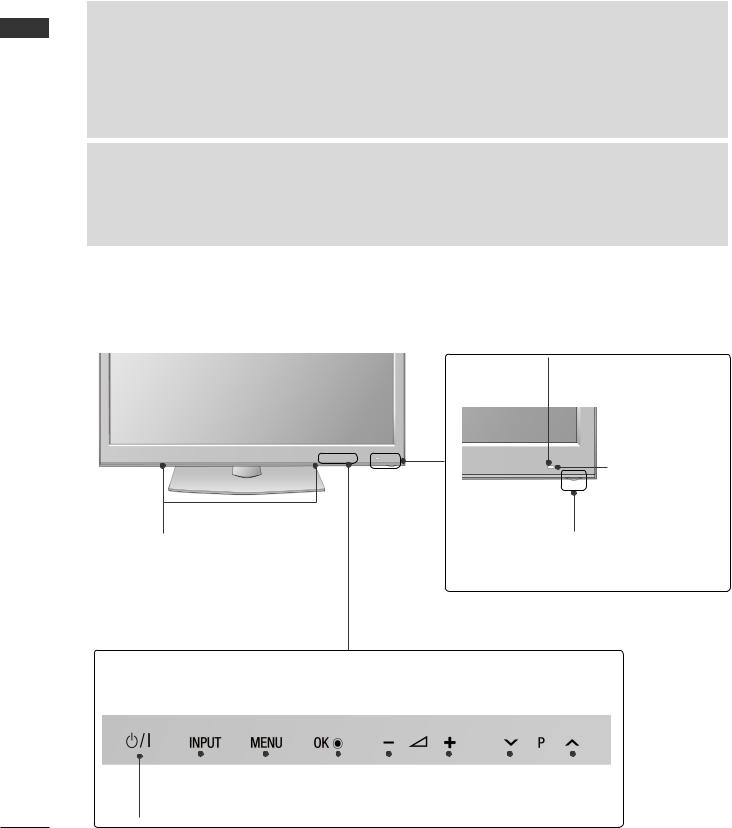
FRONT PANEL CONTROLS
 NOTE
NOTE
►TV► can be placed in standby mode in order to reduce the power consumption. And TV should be switched off using the power switch on the TV if it will not be watched for some time, as this will reduce energy consumption.
The energy consumed during use can be significantly reduced if the level of brightness of the picture is reduced, and this will reduce the overall running cost.
 CAUTION
►Do► not step on the glass stand or subject it to any impact. It may break, causing possible injury from fragments of glass, or the TV may fall.
►Do► not drag the TV. The floor or the product may be damaged.
■■ Image shown may differ from your TV.
Intelligent Sensor
Adjusts picture according to the surrounding conditions
Remote Control
Sensor
SPEAKER
Power/Standby Indicator
• Illuminates red in standby mode.
• The lighting is off while the TV remains on.
Touch Button
You can use the desired button function by touching.
|
|
|
|
|
|
|
|
POWER |
INPUT |
MENU |
OK |
VOLUME |
|
PROGRAMME |
|
A-2
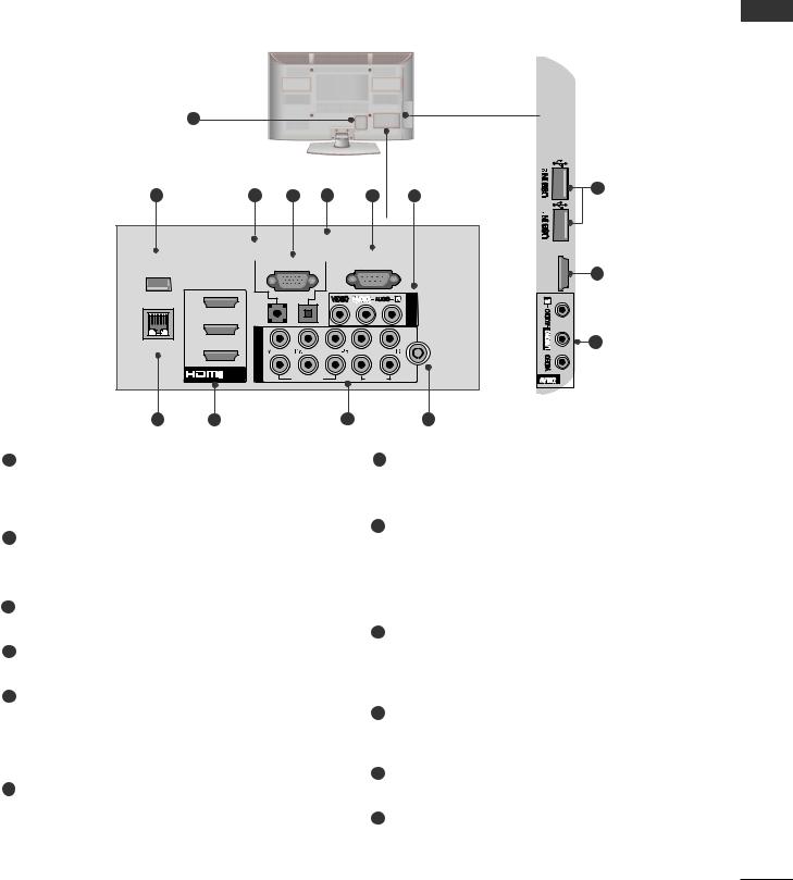
BACK PANEL INFORMATION
■■ Image shown may differ from your TV.
|
1 |
|
|
|
|
|
|
|
2 |
|
3 |
4 |
5 |
6 |
7 |
|
12 |
|
|
|
||||||
|
AUDIO IN |
|
OPTICAL |
|
|
|
|
|
|
|
DIGITAL |
|
|
<![if ! IE]> <![endif]>IN4 |
|
||
WIRELESS |
(RGB/DVI) |
|
AUDIO OUT |
RS-232C IN |
|
|
||
|
|
RGB IN (PC) |
(CONTROL & SERVICE) |
<![if ! IE]> <![endif]>/DVI |
9 |
|||
CONTROL |
|
|
|
|
|
|
||
|
|
|
|
|
|
|
<![if ! IE]> <![endif]>HDMI |
|
|
3 |
|
|
VIDEO L(MONO) AUDIO R |
<![if ! IE]> <![endif]>1 |
|
|
|
|
|
|
|
|
<![if ! IE]> <![endif]>IN |
|
|
|
|
|
|
|
|
|
<![if ! IE]> <![endif]>AV |
|
|
|
2 |
<![if ! IE]> <![endif]>IN |
|
|
|
2 |
|
|
|
|
|
|
|
|
|
||
LAN |
/DVI IN |
<![if ! IE]> <![endif]>COMPONENT |
|
VIDEO |
AUDIO |
|
7 |
|
|
|
ANTENNA |
||||||
|
1 |
|
|
|
|
1 |
IN |
|
|
|
|
|
|
|
|
|
|
8 |
9 |
|
|
|
10 |
|
11 |
|
1Power Cord Socket
This TV operates on an AC power.
Caution: Never attempt to operate the TV on DC power.
2WIRELESS Control
Connect the Wireless Ready Dongle to the TV to control the external input devices connected to Wireless Media Box wirelessly.
3RGB/DVI Audio Input
Connect the audio from a PC or DTV.
4RGB IN Input
Connect the output from a PC.
5OPTICAL DIGITAL AUDIO OUT
Connect digital audio to various types of equipment.
Connect to a Digital Audio Component. Use an Optical audio cable.
6RS-232C IN (CONTROL & SERVICE) PORT
Connect to the RS-232C port on a PC. This port is used for Service or Hotel mode.
7Audio/Video Input
Connect audio/video output from an external device to these jacks.
8LAN
Network connection for AccuWeather,
Picasa, YouTube, etc.
Also used for video, photo and music files on a local network.
9HDMI/DVI IN Input
Connect an HDMI signal to HDMI IN. Or DVI (VIDEO) signal to HDMI/DVI port with DVI to HDMI cable.
10Component Input
Connect a component video/audio device to these jacks.
11Antenna Input
Connect antenna or cable to this jack.
12USB Input
Connect USB storage device to this jack.
<![endif]>PREPARATION
A-3
PREPARATION
<![endif]>PREPARATION
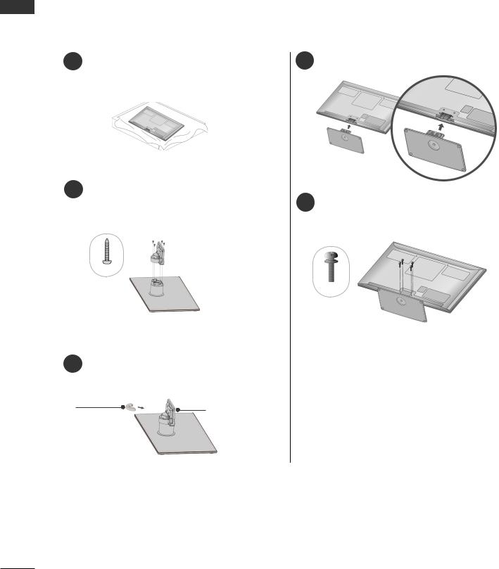
STAND INSTALLATION (only 50PK7***, 50PK9***)
■■ Image shown may differ from your TV.
When assembling the desk type stand, check whether the bolt is fully tightened. (If not tightened fully, the product can tilt forward after the product installation.) If you tighten the bolt with excessive force, the bolt can deviate from abrasion of the tightening part of the bolt.
1 |
Carefully place the TV screen side down on |
4 Assemble the TV as shown. |
a cushioned surface to protect the screen |
||
|
from damage. |
|
2Set the Stand Base on even floor. Assemble the parts of the Stand Body with the Stand Base of the TV.
 Stand Body
M4x14
 Stand Base
3Assemble the parts of the Cable Management Clip with the Stand Body.
Cable |
Stand Body |
Management |
|
Clip |
|
5Fix the 4 bolts securely using the holes in the back of the TV.
M4x28
A-4
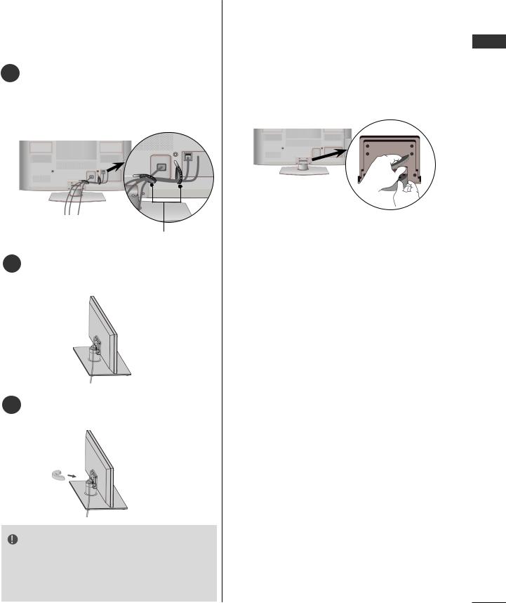
BACK COVER FOR WIRE ARRANGEMENT
■■Image shown may differ from your TV.
1 After connecting the cables as necessary, install Cable Holder as shown and bundle the cables.
In case of the LAN cable, install as shown to reduce the electromagnetic wave.
Cable Holder
2Connect the cables as necessary. To connect additional equipment, see the
External Equipment Setup section.
3Install the Cable Management Clip into the TV until clicking sound.
NOTE
►Do► not use the Cable Management Clip to lift the TV.
-If the TV is dropped, you may be injured or the TV may be damaged.
HOW TO REMOVE THE CABLE MANAGEMENT CLIP
■■ Image shown may differ from your TV.
Hold the Cable Management Clip with both hands and pull it backward as shown.
<![endif]>PREPARATION
A-5
PREPARATION
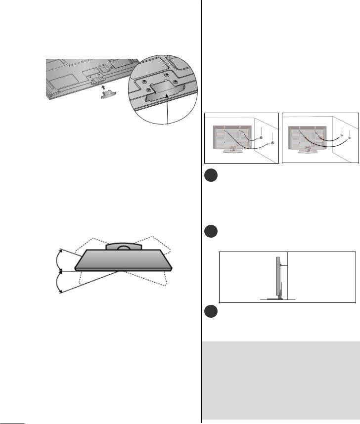
NOT USING THE DESK-
TYPE STAND
|
|
■■ Image shown may differ from your TV. |
|
| <![if ! IE]> <![endif]>PREPARATION |
|||
When installing the wall-mounted unit, use the |
|||
protection cover. |
|||
|
|
||
|
|
Insert the Protection |
|
|
|
Cover into the TV until |
|
|
|
clicking sound. |
|
|
|
Protection Cover |
|
|
|
(Fix a Guide to the Outsides.) |
|
CAREFUL INSTALLATION ADVICE
■■ You should purchase necessary components to fix the TV safety and secure to the wall on the market.
■■ Position the TV close to the wall to avoid the possibility of it falling when pushed.
■■ The instructions shown below are a safer way to set up the TV, by fixing it to the wall, avoiding the possibility of it falling forwards if pulled. This will prevent the TV from falling forward and causing injury. This will also prevent the TV from damage. Ensure that children do not climb or hang from the TV.
1 1
2
2
SWIVEL STAND
■■ Image shown may differ from your TV.
After installing the TV, you can adjust the TV set manually to the left or right direction by 20 degrees to suit your viewing position.
1Use the eye-bolts or TV brackets/bolts to fix the product to the wall as shown in the picture.
(If your TV has bolts in the eyebolts, loosen then bolts.)
* Insert the eye-bolts or TV brackets/bolts and tighten them securely in the upper holes.
2Secure the wall brackets with the bolts on the wall. Match the height of the bracket that is mounted on the wall.
3
3Use a sturdy rope to tie the product for alignment. It is safer to tie the rope so it becomes horizontal between the wall and the product.
 NOTE
NOTE
►When► moving the TV undo the cords first.
►Use► a platform or cabinet strong and large enough to support the size and weight of the TV.
►To► use the TV safely make sure that the height of the bracket on the wall and on the TV is the same.
A-6
■■The TV can be installed in various ways such as on a wall, or on a desktop etc.
■■The TV is designed to be mounted horizontally.
EARTHING
Ensure that you connect the earth wire to prevent possible electric shock. If grounding methods are not possible, have a qualified electrician install a separate circuit breaker.
Do not try to earth the TV by connecting it to telephone wires, lightening rods or gas pipes.
PowerSupply
Circuitbreaker
DESKTOP PEDESTAL INSTALLATION
■■ Image shown may differ from your TV.
For adequate ventilation allow a clearance of 10 cm all around the TV.
10 cm
10 cm
10 cm |
10 cm |
 NOTE
NOTE
►Should► Install wall mount on a solid wall perpendicular to the floor.
►Should► use a special wall mount, if you want to install it to ceiling or slanted wall.
►The► surface that wall mount is to be mounted on should be of sufficient strength to support the weight of TV set; e.g. concrete, natural rock, brick and hollow block.
►Installing► screw type and length depends on the wall mount used. Further information, refer to the instructions included with the mount.
►LG► is not liable for any accidents or damage to property or TV due to incorrect installation:
-Where a non-compliant VESA wall mount is used.
-Incorrect fastening of screws to surface which may cause TV to fall and cause personal injury.
-Not following the recommended Installation method.
10 cm
10 cm
10 cm |
10 cm |
10 cm
WALL MOUNT: HORIZONTAL INSTALLATION
■■We recommend the use of a LG Brand wall mounting bracket when mounting the TV to a wall.
■■We recommend that you purchase a wall mounting bracket which supports VESA standard.
■■LG recommends that wall mounting be performed by a qualified professional installer.
Model |
VESA Standard |
Quantity |
||
(A |
* B) |
Screw |
||
50PK7*** |
400 |
* 400 |
M6 |
4 |
60PK7*** |
600 |
* 400 |
M8 |
4 |
50PK9*** |
400 |
* 400 |
M6 |
4 |
60PK9*** |
600 |
* 400 |
M8 |
4 |
<![endif]>PREPARATION
A-7
PREPARATION
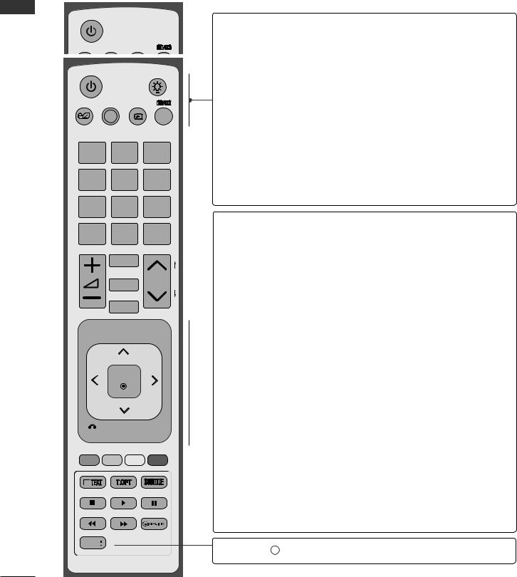
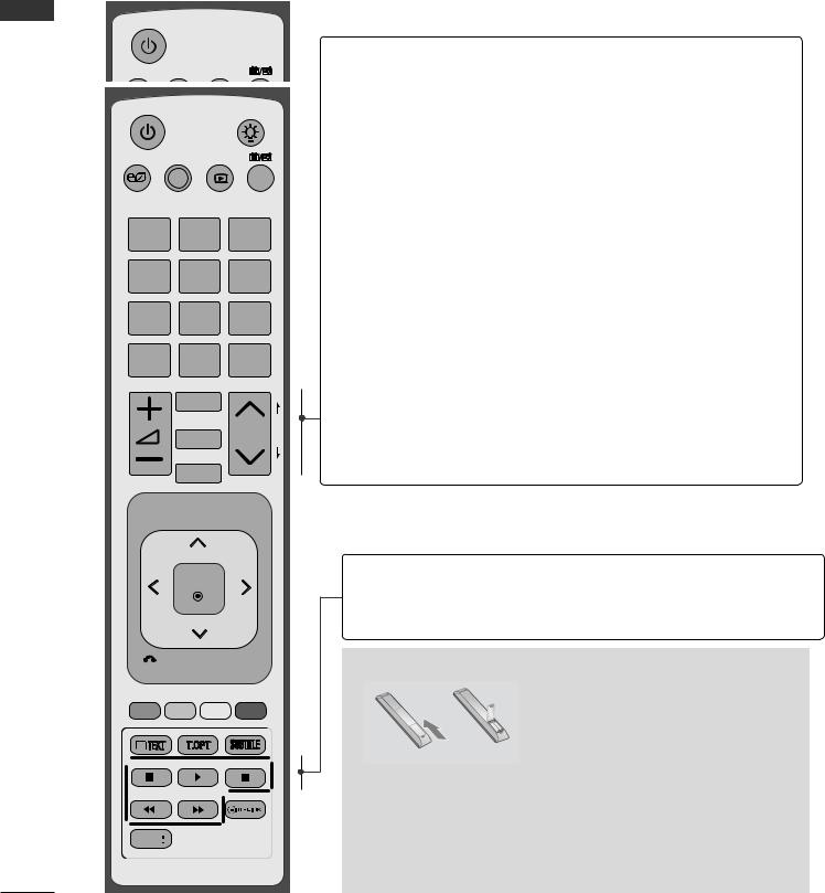
REMOTE CONTROL KEY FUNCTIONS
When using the remote control, aim it at the remote control sensor on the TV.
<![endif]>PREPARATION
ENERGY AV MODE |
INPUT |
LIGHT
ENERGY AV MODE |
INPUT |
TV/ RAD
SAVING
12ABC 3DEF
4GHI 5JKL 6MNO
7PQRS 8TUV 9XYZ
LIST 0[ |
Q.VIEW |
|
MARK |
|
|
FAV |
|
|
CHAR/NUM |
|
P |
RATIO |
P |
A |
EG |
DELETE
MUTE
MENU  Q.MENU
OK
BACK GUIDE EXIT 
FREEZE
INFO

 (POWER) Switches the TV on from standby or off to standby.
LIGHT You can turn the light of the remote control button (Only on or off.
50/60PK9***)
ENERGY Adjust the Energy Saving mode of the TV.(►p.102) SAVING
AV MODE It helps you select and set images and sounds when connecting AV devices.(►p.48)
INPUT External input mode rotate in regular sequence. (►p.43)
TV/RAD Selects Radio, TV and DTV channel.
MENU Selects a menu.
Clears all on-screen displays and returns to TV viewing from any menu.(►p.25)
NetCast SelectthedesiredNetCastmenusource.(►p.52)
(Bigpond,Weatherinfo,MovieOnline,PhotoAlbum.)
NetCastmenusourcecandifferbycountry.
Q. MENU Select the desired quick menu source. (Aspect Ratio, Clear Voice II , Picture Mode, Sound Mode, Audio Language, Sleep Timer, Skip Off/On, USB Device).(►p.24)
 THUMBSTICK Allows you to navigate the on-screen menus and (Up/Down/Left/Right) adjust the system settings to your preference.
OK Accepts your selection or displays the current mode.
BACK Allows the user to move return one step in an interactive application, EPG or other user interaction function.
EXIT Clears all on-screen displays and returns to TV viewing from any menu.
GUIDE Shows programme guide.(►p.93)
INFO i Shows the present screen information.
A-8

ENERGY AV MODE |
INPUT |
LIGHT
ENERGY AV MODE |
INPUT |
TV/
RAD
SAVING
12ABC 3DEF
4GHI 5JKL 6MNO
7PQRS 8TUV 9XYZ
LIST 0[ |
Q.VIEW |
|
MARK |
|
|
FAV |
|
|
CHAR/NUM |
|
P |
RATIO |
P |
A |
EG |
DELETE
MUTE
MENU  Q.MENU
OK
BACK GUIDE EXIT 
1
FREEZE
INFO
<![endif]>PREPARATION
0 to 9 number |
Selects a programme. |
button |
Selects numbered items in a menu. |
(Space) |
Opens an empty space on the screen keyboard. |
| <![if ! IE]> <![endif]>] |
|
LIST |
Displays the programme table. (►p.41) |
Q.VIEW |
Returns to the previously viewed programme. |
Coloured These buttons are used for teletext (on TELETEXT buttons models only), Programme edit.
1 TELETEXT These buttons are used for teletext. BUTTONS For further details, see the ‘Teletext’ section.(►
p.137)
SUBTITLE Recalls your preferred subtitle in digital mode.
FREEZE Pause the present picture at the screen. (It doesn't work at USB Mode and Simplink.)
The TV returns to normal viewing automatically if no signal is received or no operation is performed for 5 minutes.
If you keep the screen in Freeze condition, the residual image can exist.
See a list of AV devices connected to TV.
When you toggle this button, the Simplink menu appears at the screen.(►p.45)
A-9
PREPARATION
<![endif]>PREPARATION
ENERGY AV MODE |
INPUT |
LIGHT
ENERGY AV MODE |
INPUT |
TV/ RAD
SAVING
12ABC 3DEF
4GHI 5JKL 6MNO
7PQRS 8TUV 9XYZ
LIST 0[ |
Q.VIEW |
|
MARK |
|
|
FAV |
|
|
CHAR/NUM |
|
P |
RATIO |
P |
A |
EG |
DELETE
MUTE
MENU  Q.MENU
OK
BACK GUIDE EXIT 
FREEZE
INFO
VOLUME UP Adjusts the volume. /DOWN
MARK Select the input to apply the Picture Wizard settings.
Mark and un-mark programmes in the USB menu.
FAV Displays the selected favourite programme.
CHAR/NUM Shifts the Character or Number for NetCast menu.
RATIO Selects your desired Aspect Ratio of picture. (►p.99)
DELETE Deletes the entered character when entering the character on the screen keyboard.
MUTE Switches the sound on or off.
Programme Selects a programme.
UP/DOWN
PAGE UP/ Move from one full set of screen information to the DOWN next one.
SIMPLINK / Controls SIMPLINK or MY MEDIA menu (Photo List, MY MEDIA Music List and Movie List).
Menu control buttons
Installing Batteries
■■ Open the battery compartment cover on the back and install the batteries matching correct polarity (+with +,-with -).
■■Install two 1.5 V AAA batteries. Do not mix old or used batteries with new ones.
■■Close cover.
■■To remove the batteries, perform the installation actions in reverse.
A-10
EXTERNAL EQUIPMENT SETUP
■■To prevent damage do not connect to the mains outlet until all connections are made between the devices.
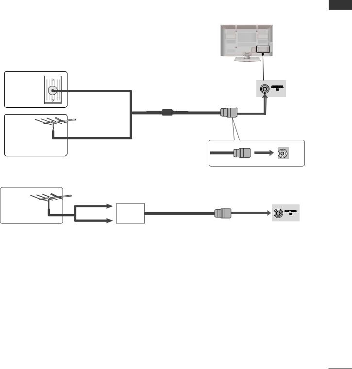
ANTENNA CONNECTION
■■For optimum picture quality, adjust antenna direction.
■■An antenna cable and converter are not supplied.
Wall |
Multi-family Dwellings/Apartments |
|
(Connect to wall antenna socket) |
||
Antenna |
||
Socket |
|
RF Coaxial Wire (75 Ω)
Outdoor
Antenna
(VHF, UHF) Single-family Dwellings /Houses
(Connect to wall jack for outdoor antenna)
|
UHF |
Antenna |
Signal |
|
Amplifier |
|
VHF |
■■In poor signal areas, to achieve better picture quality it may be necessary to install a signal amplifier to the antenna as shown above.
■■If signal needs to be split for two TVs, use an antenna signal splitter for connection.
<![endif]>SETUP EQUIPMENT EXTERNAL
1
EXTERNAL EQUIPMENT SETUP
<![endif]>SETUP EQUIPMENT EXTERNAL
■■To avoid damaging any equipment, never plug in any power cord until you have finished connecting all equipment.
■■This section on EXTERNAL EQUIPMENT SETUP mainly uses diagrams for the 50/60 PK950.
■■Image shown may differ from your TV.
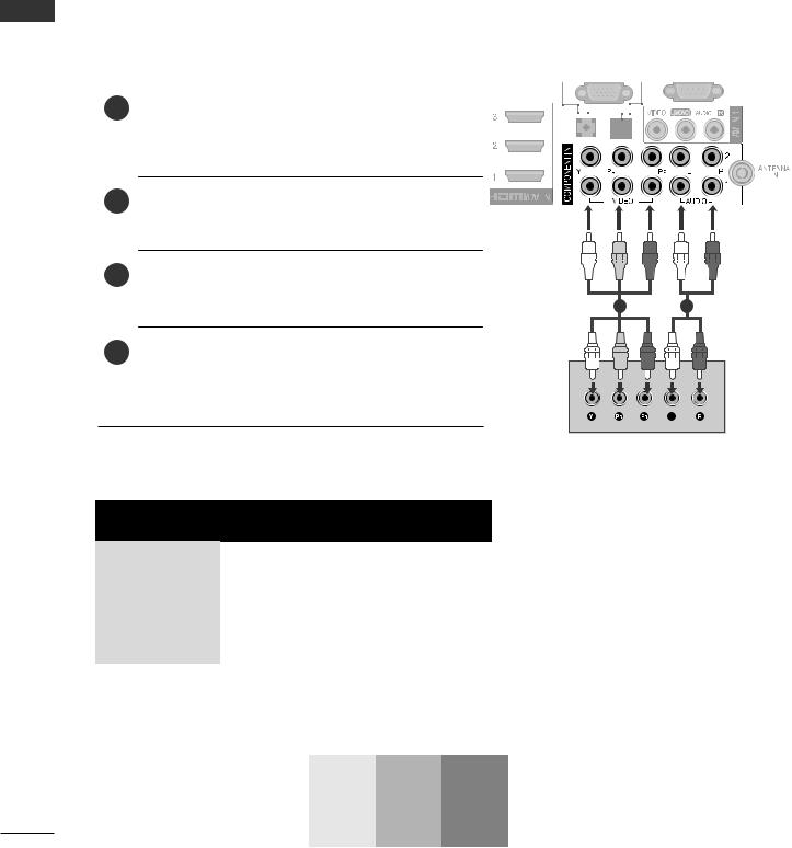
CONNECTING WITH A COMPONENT CABLE
This TV can receive Digital RF/Cable signals without an external digital set-top box. However, if you do receive Digital signals from a digital set-top box or other digital external device, refer to the diagram as shown below.
1 |
Connect the video outputs (Y, PB, PR) of the |
|
|
|
|
|
|
|
|
|
|
|
|
external equipment (digital set-top box, DVD, |
|
|
|
|
|
|
|
|
|
|
|
|
|
|
|
|
|
|
|
|
|
|
||
|
etc.) to the COMPONENT IN VIDEO jacks on |
|
|
|
|
|
|
|
|
|
|
|
|
|
|
|
|
|
|
|
|
|
|
||
|
the TV. |
|
|
|
|
|
|
|
|
|
|
|
2 |
Connect the audio output of the external equip- |
|
|
|
|
|
|
|
|
|
|
|
|
|
|
|
|
|
|
|
|
|
|||
|
|
|
|
|
|
|
|
|
|
|||
|
ment (digital set-top box, DVD, etc.) to the |
|
|
|
|
|
|
|
|
|
|
|
|
|
|
|
|
|
|
|
|
|
|
||
|
COMPONENT IN AUDIO jacks on the TV. |
|
|
|
|
|
|
|
|
|
|
|
3 |
(Turn on the external equipment. |
|
|
|
|
|
|
|
|
|
|
|
|
Refer to the external equipment's manual for |
1 |
|
|
|
|
|
|
|
|||
|
operating instructions.) |
2 |
|
|
|
|
|
|||||
4Select the COMPONENT1 input source using the INPUT button on the remote control.
If connected to COMPONENT IN 2, select
COMPONENT2 input source.
►HDMI► Audio Supported format : Dolby Digital, PCM. DTS Audio format is not supported.
Signal |
Component |
HDMI |
|
480i/576i |
O |
X |
|
480p/576p |
O |
O |
|
720p/1080i |
O |
O |
|
1080p |
O |
O |
|
(24 Hz / 30 Hz / |
|||
(50 Hz / 60 Hz only) |
|||
|
50 Hz / 60 Hz) |
||
|
|
Component Input ports
To achieve better picture quality, connect a DVD player to the component input ports as shown below.
Component ports on the TV |
Y |
PB |
PR |
|
|
|
|
|
Y |
PB |
PR |
Video output ports |
Y |
B-Y |
R-Y |
on DVD player |
Y |
Cb |
Cr |
|
Y |
Pb |
Pr |
2
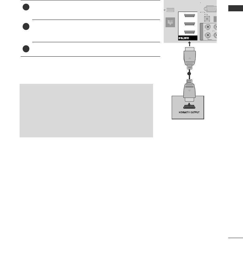
CONNECTING WITH AN HDMI CABLE
1Connect the HDMI output of the external equipment (digital settop box, DVD, etc.) to HDMI/DVI IN 1, HDMI/DVI IN 2, HDMI/ DVI IN 3, HDMI/DVI IN 4 jack on the TV.
2Turn on the external equipment.
(Refer to the external equipment's manual for operating instructions.)
3Select HDMI1, HDMI2, HDMI3, HDMI4 input source using the INPUT button on the remote control.
 NOTE
NOTE
►The► TV can receive video and audio signals simultaneously when using an HDMI cable.
►If► the DVD does not support Auto HDMI, you must set the output resolution appropriately.
►Check► that your HDMI cable is High Speed HDMI Cable. If the HDMI cables are not High Speed HDMI Cable, flickering or no screen display can result. Please use the High Speed HDMI Cable.
|
|
|
|
|
|
|
|
|
|
|
|
|
|
(RGB/DVI) |
|
||||
|
|
|
|
|
|
|
|
|
|
WIRELESS |
|
|
|
RGB IN |
|
(PC |
|||
|
|
|
|
|
|
||||
|
|
|
|
|
|
|
|
|
|
|
CONTROL |
|
|
|
|
|
|
||
3
2
LAN
1
|
|
/DVI IN |
|
|
|
|
|
||
VI |
||||
|
|
|||
|
|
|
|
1
<![endif]>SETUP EQUIPMENT EXTERNAL
3
EXTERNAL EQUIPMENT SETUP
CONNECTING WITH AN HDMI TO DVI CABLE
<![endif]>SETUP EQUIPMENT EXTERNAL
1Connect the digital set-top box or the DVI output of the PC to HDMI/DVI IN 1, HDMI/DVI IN 2, HDMI/DVI IN 3, HDMI/DVI IN 4 jack on the TV.
2Connect the audio output of the digital set-top box or the PC audio output to the AUDIO IN (RGB/DVI) jack on the TV.
3Turn on the digital set-top box or the PC and the TV.
(Refer to the digital set-top box or the PC manual for operating instructions.)
4Select HDMI1, HDMI2, HDMI3, HDMI4 input source using the INPUT button on the remote control.
|
|
|
|
|
|
|
|
|
|
|
|
|
|
|
|
|
|
|
|
|
|
|
|
|
|
AUDIO IN |
|
|
|
|
|
OPTICAL |
|
|
|
|
|
|
|
|
|
|
|||
|
|
|
|
|
|
|
|
|
DIGITAL |
|
|
|
|
|
|
|
|
|
|
|
||
|
|
|
(RGB/DVI) |
|
|
|
|
|
|
|
|
|
|
|
|
|
|
|
|
|
||
|
|
|
|
|
|
|
|
AUDIO OU |
T |
|
|
RS-232C IN |
|
|
|
|
|
|
||||
|
|
|
|
|
|
|
|
|
|
|
|
|
|
|
|
|
|
|||||
|
|
|
|
|
|
|
|
|
|
|
|
|
|
|
|
|
|
|
|
|
|
|
IRELESS |
|
|
RGB IN |
|
(PC) |
|
|
|
(CONTROL & SERVICE) |
|
|
|
|
|
||||||||
|
|
|
|
|
|
|
|
|
|
|
|
|
|
|||||||||
ONTROL |
3 |
|
|
|
|
|
|
|
|
|
|
|
|
|
|
<![if ! IE]> <![endif]>IN 1 |
|
|
|
|
||
|
|
|
|
|
|
|
|
|
|
|
|
|
|
|
|
|
|
|
|
|
||
|
|
|
|
|
|
|
|
|
|
|
|
|
|
|
|
|
|
|
|
|
||
|
|
|
|
|
|
|
|
|
|
|
|
|
|
|
|
|||||||
|
|
|
2 |
|
|
|
|
|
|
|
|
|
|
|
|
|
|
<![if ! IE]> <![endif]>AV |
|
|
|
|
|
|
|
|
|
|
|
|
|
|
|
|
|
|
|
|
|
|
|
|
|
|
|
|
|
|
|
|
|
|
|
|
|
|
|
|
|
|
|
|
|
|
|
|
|
|
|
|
|
|
|
|
|
|
|
|
|
|
|
|
|
|
|
|
|
|
|
|
|
LAN |
|
|
|
|
|
|
|
|
|
|
|
|
|
|
|
|||||||
|
|
1 |
|
|
|
|
|
|
|
|
|
|
|
|
|
|
|
|
ANTENNA |
|||
|
|
|
|
|
|
|
|
|
|
|
|
|
|
|
|
|
|
|
|
|
||
|
|
|
|
|
|
|
|
|
|
|
|
|
|
|
|
|
|
|
|
IN |
|
|
|
|
|
|
|
|
|
|
|
|
|
|
|
|
|
|
|
|
|
|
|||
|
|
|
|
|
|
|
|
|
|
|
|
|
|
|
|
|
|
|
|
|
|
|
 /DVI IN
12
or 
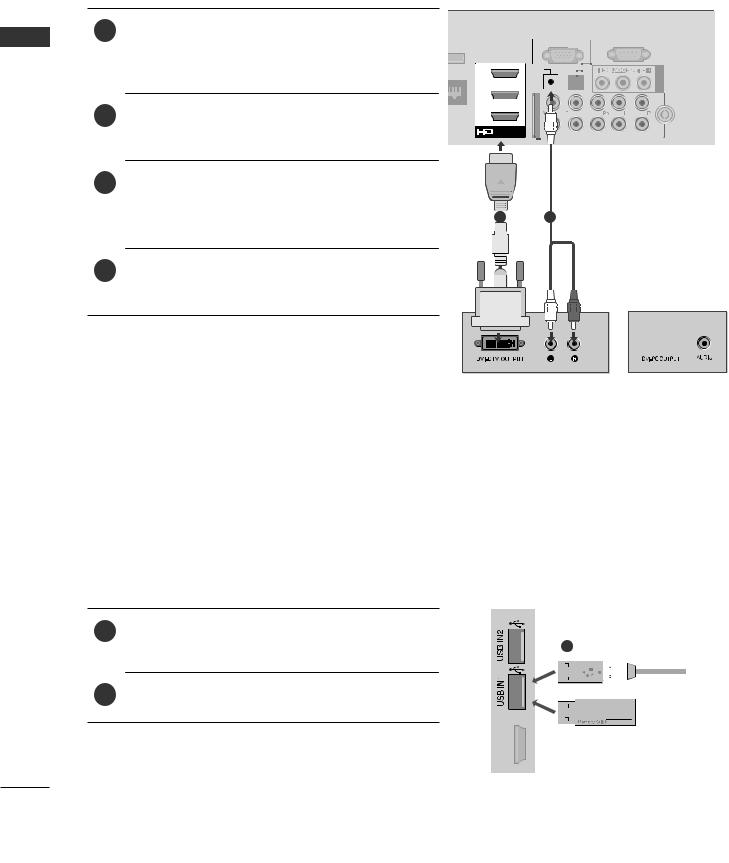
USB SETUP
1Connect the USB device to the USB IN 1 or USB IN 2 jack on the TV.
2After connecting the USB IN 1 or USB IN 2 jack, you use the USB function. (► p.60)
1
 or
or
<![endif]>HDMI/DVIIN4
4
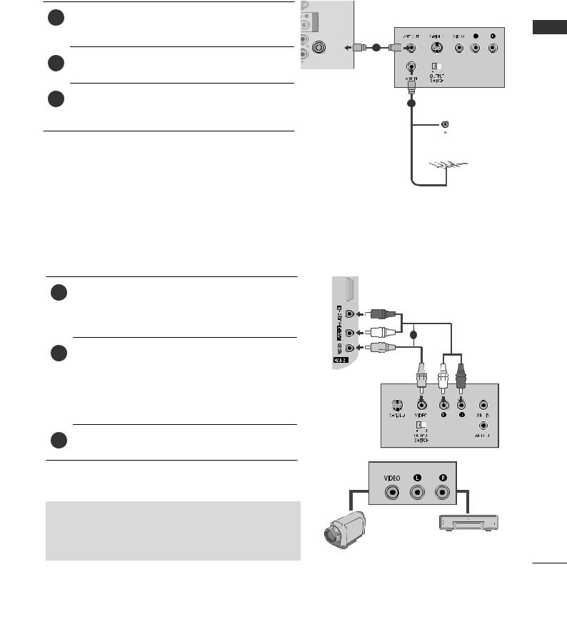
CONNECTING WITH AN RF CABLE
To avoid picture noise (interference), allow adequate distance between the VCR and TV.
1 Connect the ANT OUT socket of the VCR to |
<![if ! IE]> <![endif]>IN 1 |
the ANTENNA IN socket on the TV. |
<![if ! IE]> <![endif]>AV |
|
|
|
|
ANTENNA |
1 |
IN |
2Connect the antenna cable to the ANT IN socket of the VCR.
3 |
Press the PLAY button on the VCR and match |
2 Wall Jack |
|
the appropriate channel between the TV and |
VCR for viewing.  Antenna
CONNECTING WITH AN RCA CABLE
1Connect the AUDIO/VIDEO jacks between TV and VCR or external equipment. Match the jack colours. (Video = yellow, Audio Left = white, and Audio Right = red)
2Insert a video tape into the VCR and press PLAY on the VCR. (Refer to the VCR owner’s manual.)
Or, Operate the corresponding external equipment. (Refer to external equipment operating guide.)
3Select AV1, AV2 input source using the INPUT button on the remote control.
 NOTE
NOTE
►If► you have a mono VCR, connect the audio cable from the VCR to the AUDIO L/MONO jack of the TV.
<![endif]>HDMI/DVIIN4
Camcorder
1
or
Video Game Set
<![endif]>SETUP EQUIPMENT EXTERNAL
5
EXTERNAL EQUIPMENT SETUP
<![endif]>SETUP EQUIPMENT EXTERNAL
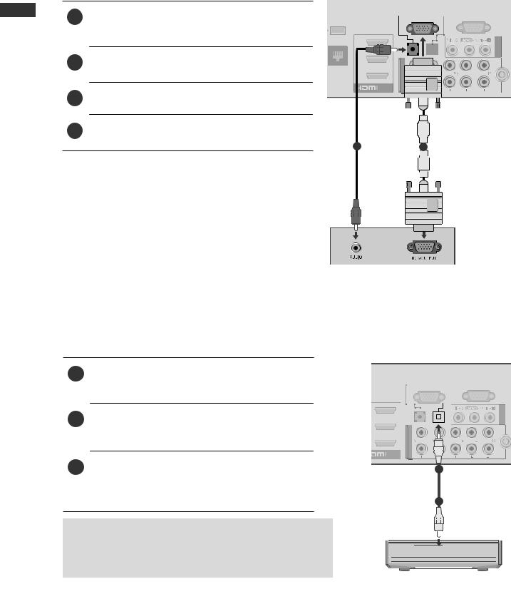
CONNECTING WITH A D-SUB 15 PIN CABLE
This TV provides Plug and Play capability, meaning that the PC adjusts automatically to the TV's settings.
1Connect the RGB output of the PC to the RGB IN (PC) jack on the TV.
2Connect the PC audio output to the AUDIO IN (RGB/DVI) jack on the TV.
3Turn on the PC and the TV
4Select RGB input source using the INPUT button on the remote control.
|
|
|
|
|
|
|
|
|
|
|
|
|
|
|
|
AUDIO IN |
OPTICAL |
|
|
|
|
||||
|
|
|
|
|
DIGITAL |
|
|
|
|
|
||
|
|
|
(RGB/DVI) |
|
|
|
|
|
|
|||
|
|
|
|
AUDIO OUT |
|
|
RS-232C IN |
|
||||
|
|
|
RGB IN (PC) |
|
|
|
||||||
|
|
|
|
|
|
|||||||
WIRELESS |
|
(CONTROL & SERVICE) |
||||||||||
|
|
|
||||||||||
|
||||||||||||
|
CONTROL |
|
|
|
|
|
|
|
|
|
||
3 |
<![if ! IE]> <![endif]>IN 1 |
|
<![if ! IE]> <![endif]>AV |
LAN

 /DVI IN
21
DIGITAL AUDIO OUT SETUP
Sending the TV’s audio signal to external audio equipment via the Digital Audio Output (Optical) port.
If you want to enjoy digital broadcasting through 5.1-channel speakers, connect the OPTICAL DIGITAL AUDIO OUT terminal on the back of TV to a Home Theater (or amp).
1Connect one end of an optical cable to the TV Digital Audio (Optical) Output port.
2Connect the other end of the optical cable to the digital audio (Optical) input on the audio equipment.
3Set the “TV Speaker option - Off ” in the AUDIO menu.(►p.119). Refer to the external audio equipment instruction manual for operation.
|
|
|
|
|
|
OPTICAL |
|
|
|
|
|
|
||
AUDIO IN |
|
DIGITAL |
|
|
|
|
|
|
||||||
(RGB/DVI) |
|
AUDIO OUT |
|
|
|
|
|
|
||||||
|
|
RS-232C IN |
||||||||||||
|
|
|
|
|
|
|
|
|
|
|
|
|
|
|
|
|
RGB IN |
|
(PC) |
|
|
|
(CONTROL & SERVICE) |
<![if ! IE]> <![endif]>AV IN 1 |
|||||
|
|
|
|
|
|
|
|
|
|
|
|
|
|
|
|
|
|
|
|
|
|
|
|
|
|
|
|
|
|
|
|
|
|
|
|
|
|
|
|
|
|
|
|
|
|
|
|
|
|
|
|
|
|
|
|
|
|
|
|
|
|
|
|
|
|
|
|
|
|
|
|
|
|
|
|
|
|
|
|
|
|
|
|
|
|
|
|
|
|
|
|
|
|
|
|
|
|
|
|
|
|
|
|
|
|
|
|
|
|
|
|
|
|
|
|
|
|
|
|
|
|
|
|
|
|
|
|
|
|
|
|
|
|
|
|
|
|
|
|
|
|
|
|
|
|
|
|
|
|

 /DVI IN
1
2
 CAUTION
6 |
►►Do not look into the optical output port. Looking at the laser |
|
|
|
|
|
|||
beam may damage your vision. |
|
|
|
|
|
|
|
||
EXTERNAL EQUIPMENT WIRELESS CONNECTION
LG TVs with a Wireless Control port support the LG Wireless Media Box, which is sold
separately. When you connect the Wireless Ready Dongle (included with the Wireless Media Box) to the TV, external devices can be connected to the LG Wireless Media Box and video and audio will be sent to the TV wirelessly.
After the wireless is connected, press the INPUT button to view the wireless input screen. Refer to the Wireless Media Box manual for operating instructions.
Connect the WIRELESS CONTROL jack of the
1Wireless Ready Dongle to the WIRELESS CONTROL jack on the TV.
2Connect HDMI OUT jack of the Wireless Ready Dongle to the HDMI/DVI IN 1, HDMI/ DVI IN 2, HDMI/DVI IN 3, HDMI/DVI IN 4 jack on the TV.
LG Wireless Ready Dongle
AV1 |
AV2 COM1 COM2 RGB |
HDMI 1 HDMI 2 HDMI 3 HDMI 4 WIRELESS |
WIRELESS |
OUT |
|
CONTROL |
||
|
LG Wireless Media Box
AUDIO IN
(RGB/DVI)
WIRELESS |
|
|
|
|
RGB IN |
(PC |
|||
CONTROL |
|
|
|
|
3
2
LAN
1
|
/DVI IN |
|
|
|
|
|
|
||
VID |
||||
|
|
 NOTE
NOTE
►►WIRELESS CONTROL : Wireless Ready Dongle power supply and control usage. ►►HDMI : Video/Audio signal is connected in Wireless Ready Dongle.
►When► you connect to the Wireless Media Box (Separately sold product), you can watch the external device connected to the Wireless Media Box through wireless connection.
►When► using the external device connected to the Wireless Media Box, some functions of the TV. ►In► wireless external output, Real Cinema and Digital Noise Reduction functions are not supported.
<![endif]>SETUP EQUIPMENT EXTERNAL
7
EXTERNAL EQUIPMENT SETUP
<![endif]>SETUP EQUIPMENT EXTERNAL
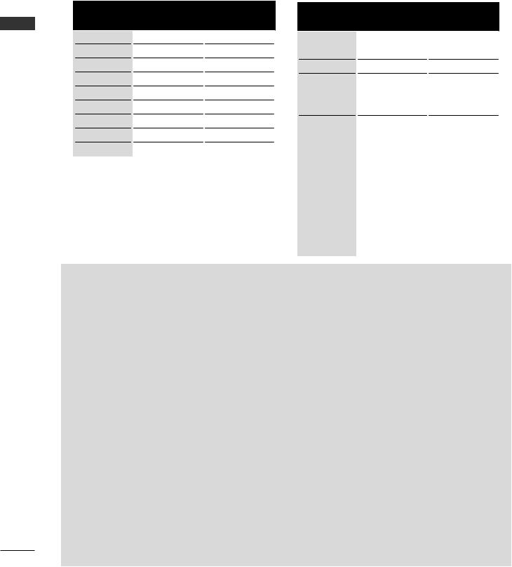
SUPPORTED DISPLAY RESOLUTION
RGB-PC, HDMI/DVI-PC mode |
HDMI/DVI-DTV mode |
|
Horizontal |
Vertical |
|
Resolution |
Frequency |
||
Frequency (Hz) |
|||
|
(kHz) |
||
|
|
||
720x400 |
31.469 |
70.08 |
|
640x480 |
31.469 |
59.94 |
|
800x600 |
35.156 |
56.25 |
|
800x600 |
37.879 |
60.31 |
|
1024x768 |
48.363 |
60.00 |
|
1280x768 |
47.693 |
59.992 |
|
1360x768 |
47.712 |
60.015 |
|
1280x1024 |
63.981 |
60.020 |
|
1920x1080 |
66.587 |
59.934 |
|
Horizontal |
Vertical |
|
Resolution |
Frequency |
||
Frequency (Hz) |
|||
|
(kHz) |
||
|
|
||
720x480 |
31.47 |
59.94 |
|
31.47 |
60 |
||
|
|||
720x576 |
31.25 |
50 |
|
|
37.5 |
50 |
|
1280x720 |
44.96 |
59.94 |
|
|
45 |
60 |
|
|
33.72 |
59.94 |
|
|
33.75 |
60 |
|
|
28.125 |
50 |
|
|
26.97 |
23.94 |
|
1920x1080 |
27 |
24 |
|
33.71 |
29.97 |
||
|
|||
|
33.75 |
30.00 |
|
|
56.25 |
50 |
|
|
67.432 |
59.939 |
|
|
67.5 |
60 |
 NOTE
NOTE
►Avoid► keeping a fixed image on the set’s screen for prolonged periods of time. The fixed image may become permanently imprinted on the screen; use a screen saver when possible.
►There► may be interference relating to resolution, vertical pattern, contrast or brightness in PC mode. Change the PC mode to another resolution or change the refresh rate to another rate or adjust the brightness and contrast on the menu until the picture is clear. If the refresh rate of the PC graphic card can not be changed, change the PC graphic card or consult the manufacturer of the PC graphic card.
►The► synchronization input waveform for Horizontal and Vertical frequencies are separate.
►We► recommend using 1920x1080, 60 Hz for the PC mode, this should provide the best picture quality.
►Connect► the signal cable from the monitor output port of the PC to the RGB (PC) port of the TV or the signal cable from the HDMI output port of the PC to the HDMI IN (or HDMI/DVI IN) port on the TV.
►Connect► the audio cable from the PC to the Audio input on the TV. (Audio cables are not included with the TV).
►If► using a sound card, adjust PC sound as required.
►If► the graphic card on the PC does not output analogue and digital RGB simultaneously, connect only one of either RGB or HDMI IN (or HDMI/DVI IN) to display the PC output on the TV.
►If► the graphic card on the PC does output analogue and digital RGB simultaneously, set the TV to either RGB or HDMI; (the other mode is set to Plug and Play automatically by the TV.)
►DOS► mode may not work depending on the video card if you use an HDMI to DVI cable.
►If► you use too long an RGB-PC cable, there may be interference on the screen. We recommend using under 5m of cable. This provides the best picture quality.
8
SCREEN SETUP FOR PC MODE
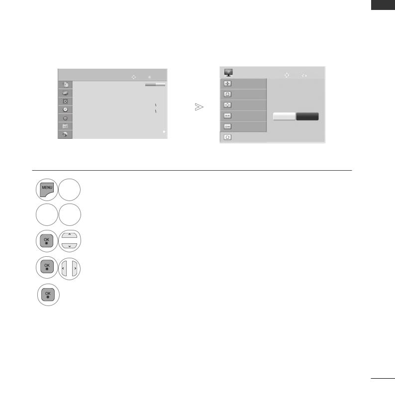
Screen Reset
Returns Position, Size and Phase to the factory default settings.
This function works in the following mode : RGB[PC].
|
|
|
PICTURE |
Move |
|
|
OK |
|
|
|
SCREEN |
Move |
Prev. |
||||
|
|
|
|
|
|
|
|
|
|
|
|
|
|
|
|
||
|
|
|
|
• Brightness |
50 |
|
|
|
|
|
|
|
|
|
Resolution |
|
|
|
|
|
|
• Sharpness |
65 |
|
|
|
|
|
|
|
|
|
Auto Config. |
|
|
|
|
|
|
|
|
|
|
|
|
|
|
|
|
|
|||
|
|
|
|
|
|
|
|
|
|
|
|
|
|
|
|||
|
|
|
|
• Colour |
60 |
|
|
|
|
|
|
|
|
|
|
|
|
|
|
|
|
|
|
|
|
|
|
|
|
|
|
|
|
||
|
|
|
|
|
|
|
|
|
|
||||||||
|
|
|
|
• Tint |
0 |
|
|
|
|
|
|
|
|
|
Position |
|
|
|
R |
|
|
|
|
G |
|
To Set |
|
||||||||
|
|
|
|
|
|
|
|
|
|||||||||
|
|
|
|
• Colour Temp. |
0 |
|
|
|
|
|
|
|
|
|
|
|
|
|
|
|
|
|
|
W |
|
|
|
|
C |
|
Size |
Yes |
No |
||
|
|
|
|
• Advanced Control |
|
|
|
|
|
|
|
||||||
|
|
|
|
• Picture Reset |
|
|
|
|
|
|
|
|
|
|
Phase |
|
|
|
|
|
|
|
|
|
|
|
|
|
|
|
|
|
|
|
|
|
|
|
|
••Screencr |
|
|
|
|
|
|
|
|
<![if ! IE]> <![endif]>► |
|
|
|
|
|
|
|
|
|
|
|
|
|
|
|
|
|
|
|
|
|
|
Reset
 Select PICTURE.
3

 Select Screen.
Select Reset.
4
Select Yes.
5
Run Reset.
•Press the MENU/EXIT button to return to normal TV viewing.
•Press the BACK button to move to the previous menu screen.
<![endif]>SETUP EQUIPMENT EXTERNAL
9
EXTERNAL EQUIPMENT SETUP
<![endif]>SETUP EQUIPMENT EXTERNAL
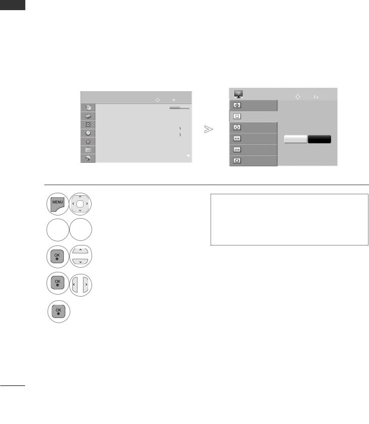
Auto Configure (RGB [PC] mode only)
Automatically adjusts the picture position and minimizes image instability. After adjustment, if the image is still not correct, your TV is functioning properly but needs further adjustment.
Auto configure
This function is for automatic adjustment of the screen position, size, and phase The displayed image will be unstable for a few seconds while the auto configuration is in progress.
|
|
|
PICTURE |
Move |
|
|
OK |
|
|
SCREEN |
Move |
Prev. |
||||
|
|
|
|
|
|
|
|
|
|
|||||||
|
|
|
|
• Brightness |
50 |
|
|
|
|
|
|
|
|
Resolution |
|
|
|
|
|
|
|
|
|
|
|
|
|
|
|
|
|
||
|
|
|
|
• Sharpness |
65 |
|
|
|
|
|
|
|
|
Auto Config. |
|
|
|
|
|
|
|
|
|
|
|
|
|
|
|
|
|||
|
|
|
|
|
|
|
|
|
|
|
|
|
|
|||
|
|
|
|
• Colour |
60 |
|
|
|
|
|
|
|
|
Position |
|
|
|
|
|
|
|
|
|
|
|
|
|
|
|
|
|||
|
|
|
|
|
|
|
|
|
||||||||
|
|
|
|
• Tint |
0 |
|
|
|
|
|
|
|
|
Auto Config. |
||
|
R |
|
|
|
G |
|
||||||||||
|
|
|
|
|
|
|
||||||||||
|
|
|
|
• Colour Temp. |
0 |
|
W |
|
|
|
C |
|
|
Size |
Yes |
No |
|
|
|
|
• Advanced Control |
|
|
|
|
|
|
|
|||||
|
|
|
|
|
|
|
|
|
|
|
|
|
|
|||
|
|
|
|
• Picture Reset |
|
|
|
|
|
|
|
|
|
Phase |
|
|
|
|
|
|
|
|
|
|
|
|
|
|
|
|
|
|
|
|
|
|
|
••Screencr |
|
|
|
|
|
|
<![if ! IE]> <![endif]>► |
|
|
|
|
|
|
|
|
|
|
|
|
|
|
|
|
|
|
|
Reset |
|
|
|
|
|
|
|
|
|
|
|
|
|
|
|
|
|
|
|
Select PICTURE.

 Select Screen.
Select Auto Config.
•If the position of the image is still not correct, try Auto adjustment again.
•If picture needs to be adjusted again after Auto adjustment in RGB (PC), you can adjust the Position, Size or Phase.
Select Yes.
Run Auto Config.
•Press the MENU/EXIT button to return to normal TV viewing.
•Press the BACK button to move to the previous menu screen.
10
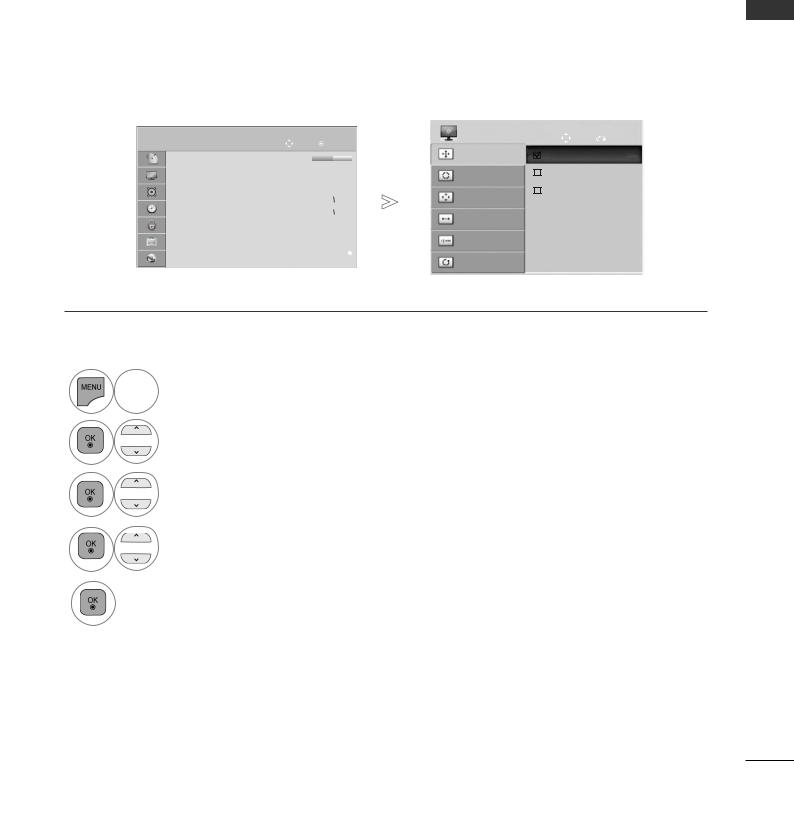
Selecting Resolution
To view a normal picture, match the resolution of RGB mode and selection of PC mode.
This function works in the following mode: RGB[PC]
|
|
|
PICTURE |
Move |
|
|
OK |
SCREEN |
|
|
Move |
Prev. |
||||
|
|
|
|
|
|
|
|
|
|
|||||||
|
|
|
|
• Brightness |
50 |
|
|
|
|
|
|
Resolution |
|
|
1024 x 768 |
|
|
|
|
|
|
|
|
|
|
|
|
|
|||||
|
|
|
|
|
|
|
||||||||||
|
|
|
|
• Sharpness |
65 |
|
|
|
|
|
|
Auto Config. |
|
|
1280 x 768 |
|
|
|
|
|
|
|
|
|
|
|
|
|
|
||||
|
|
|
|
• Colour |
60 |
|
|
|
|
|
|
|
|
1360 x 768 |
|
|
|
|
|
|
|
|
|
|
|
|
|
|
|
||||
|
|
|
|
• Tint |
0 |
|
|
|
|
|
|
Position |
|
|
|
|
R |
|
|
|
G |
|
|
|
|
||||||||
|
|
|
|
• Colour Temp. |
0 |
|
|
|
|
|
|
|
|
|
|
|
|
W |
|
|
|
C |
Size |
|
|
|
|
||||||
|
|
|
|
• Advanced Control |
|
|
|
|
|
|
|
|
|
|||
|
|
|
|
|
|
|
|
|
|
|
|
|
|
|||
|
|
|
|
• Picture Reset |
|
|
|
|
|
|
|
Phase |
|
|
|
|
|
|
|
|
|
|
|
|
|
|
|
|
|
|
|
|
|
|
|
|
|
••Screencr |
|
|
|
|
|
|
<![if ! IE]> <![endif]>► |
|
|
|
|
|
|
|
|
|
|
|
|
|
|
|
|
|
|
|
|
|
|
Reset
 Select PICTURE.
Select Screen.
3
Select Resolution.
4
Select the desired resolution.
5
•Press the MENU/EXIT button to return to normal TV viewing.
•Press the BACK button to move to the previous menu screen.
<![endif]>SETUP EQUIPMENT EXTERNAL
11
EXTERNAL EQUIPMENT SETUP
<![endif]>SETUP EQUIPMENT EXTERNAL
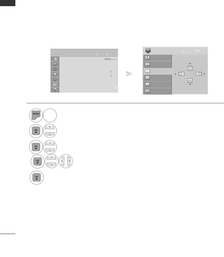
Adjustment for screen Position, Size, Phase
If the picture is not clear after auto adjustment and especially if characters are still trembling, adjust the picture position manually.
This function works in the following mode : RGB[PC].
|
|
|
PICTURE |
|
|
|
|
|
|
|
|
|
|
SCREEN |
Move |
Prev. |
|
|
|
|
|
|
|
|
|
|
|
|
|
|
|
||||
|
|
|
Move |
|
|
OK |
|
|
|
|
|
||||||
|
|
|
|
• Brightness |
50 |
|
|
|
|
|
|
|
|
|
Resolution |
|
|
|
|
|
|
|
|
|
|
|
|
|
|
|
|
|
|
||
|
|
|
|
• Sharpness |
65 |
|
|
|
|
|
|
|
|
|
Auto Config. |
|
|
|
|
|
|
|
|
|
|
|
|
|
|
|
|
|
|||
|
|
|
|
|
|
|
|
|
|
|
|
|
|
|
|||
|
|
|
|
• Colour |
60 |
|
|
|
|
|
|
|
|
|
Position |
|
|
|
|
|
|
|
|
|
|
|
|
|
|
|
|
|
|||
|
|
|
|
|
|
|
|
|
|||||||||
|
|
|
|
• Tint |
0 |
|
|
|
|
|
|
|
|
|
|
|
|
|
R |
|
|
|
G |
|
|
|
|||||||||
|
|
|
|
• Colour Temp. |
0 |
|
|
|
|
|
|
|
|
|
|
|
|
|
|
W |
|
|
|
C |
|
|
Size |
|
|
||||||
|
|
|
|
• Advanced Control |
|
|
|
|
|
|
|
|
|
||||
|
|
|
|
|
|
|
|
|
|
|
|
|
|
||||
|
|
|
|
• Picture Reset |
|
|
|
|
|
|
|
|
|
|
Phase |
|
|
|
|
|
|
|
|
|
|
|
|
|
|
|
|
|
|
|
|
|
|
|
|
••Screencr |
|
|
|
|
|
|
|
<![if ! IE]> <![endif]>► |
|
|
|
|
|
|
|
|
|
|
|
|
|
|
|
|
|
|
|
|
Reset |
|
|
|
|
|
|
|
|
|
|
|
|
|
|
|
|
|
|
|
|
 Select PICTURE.
Select Screen.
3
Select Position, Size or Phase.
4 |
Make appropriate adjustments. |
|
5
•Press the MENU/EXIT button to return to normal TV viewing.
•Press the BACK button to move to the previous menu screen.
12
NETWORK SETUP
Wired Network Connection
This TV can be connected to a local area network (LAN) via the LAN port. After making the physical connection, the TV needs to be set up for network communication.
|
|
|
|
|
|
|
|
|
|
AUDIO IN |
|
|
|
|
OPTICAL |
|
|
|
|
|||
|
|
|
|
|
|
|
|
|
|
|
|
|
|
|
DIGITAL |
|
|
|
|
|||
|
|
|
|
|
|
|
|
|
(RGB/DVI) |
|
|
|
A |
UDIO OUT |
RS-232C IN |
|
|
|
||||
|
WIRELESS |
|
|
|
|
|
|
|
|
|
|
RGB IN |
(PC) |
|
|
(CONTROL & SERVICE) |
|
|
|
|||
|
CONTROL |
|
3 |
|
|
|
|
|
|
|
|
|
|
|
|
|
|
|
<![if ! IE]> <![endif]>1 |
|
||
|
|
|
|
|
|
|
|
|
|
|
|
|
|
|
|
|
|
|
|
|
||
|
|
|
|
|
|
|
|
|
|
|
|
|
|
|
|
|
|
|
<![if ! IE]> <![endif]>AV IN |
|
||
|
|
|
|
|
|
|
|
|
|
|
|
|
|
|
|
|
|
|
|
|
||
|
|
|
|
|
|
|
|
|
|
|
|
|
|
|
|
|
|
|
|
|||
|
|
|
|
|
|
|
|
|
|
|
|
|
|
|
|
|
|
|
|
|
|
|
|
|
|
|
|
|
|
|
|
|
|
|
|
|
|
|
|
|
|
|
|
|
|
|
|
|
|
|
|
|
|
|
|
|
|
|
|
|
|
|
|
|
|
|
|
|
|
|
|
|
|
|
|
|
|
|
|
|
|
|
|
|
|
|
|
|
|
|
|
|
|
LAN |
|
|
|
|
|
|
|
|
|
|
|
|
|
|
|
|
|
ANTENNA |
||
|
|
|
|
|
1 |
|
1 |
|
|
|
|
|
|
|
|
|
|
|
|
|
IN |
|
|
|
|
|
|
|
|
|
|
|
|
|
|
|
|
|
|
|
|
|
|
|
|
|
|
|
|
|
|
|
|
|
|
|
|
|
|
|
|
|
|
|
|
|
|
|
|
|
|
|
|
|
|
|
|
|
|
|
|
|
|
|
|
|
|
|
|
|
|
Broadband Modem |
|
|
|
|
|
|
|
|
|
|
|
|
Router |
|||||||||||||
|
|
|
|
|
|
|
|
|
|
|
|
|||||||||||||||
|
|
|
|
|
|
|
|
|
|
|||||||||||||||||
|
|
|
|
|
|
|
|
|
|
|
|
|
|
|
|
|
|
|
|
|
|
|
|
|
|
|
|
|
|
|
|
|
|
|
|
|
|
|
|
|
|
|
|
|
|
|
|
|
|
|
|
|
|
|
|
|
|
|
|
|
|
|
|
|
|
|
|
|
|
|
|
|
|
|
|
|
|
|
|
|
|
|
|
|
|
|
|
|
|
|
|
|
|
|
|
|
|
|
|
|
|
|
|
|
|
|
|
|
|
|
|
|
|
|
|
|
|
|
|
|
|
|
|
|
|
|
|
|
|
|
|
|
|
|
Broadband Service |
|
|
|
|
|
|
|
Broadband Modem |
||||
|
|
|
|
|
|
|
|
|
|
|
|
|
|
|
|
|
|
|
|
|
|
|
|
|
|
|
|
|
|
|
|
|
|
|
|
|
|
|
|
|
|
|
|
|
|
|
|
|
|
|
|
|
|
|
|
|
|
|
|
|
|
|
|
|
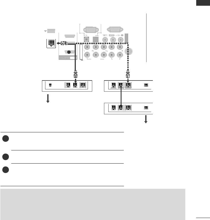
Broadband Service
1Connect the LAN port of the Modem or Router to the LAN port on the TV.
2Select “Network Setting” in the NETWORK menu.
3After connecting the LAN port, use the NetCast menu. For more information about NetCast setup and troubleshooting, visit http://lgknowledgebase.com. Search for
NetCast.
 CAUTION
►Do► not connect a modular phone cable to the LAN port.
►Since► there are various connection methods, please follow the specifications of your telecommunication carrier or internet service provider.
<![endif]>SETUP EQUIPMENT EXTERNAL
13
EXTERNAL EQUIPMENT SETUP
<![endif]>SETUP EQUIPMENT EXTERNAL
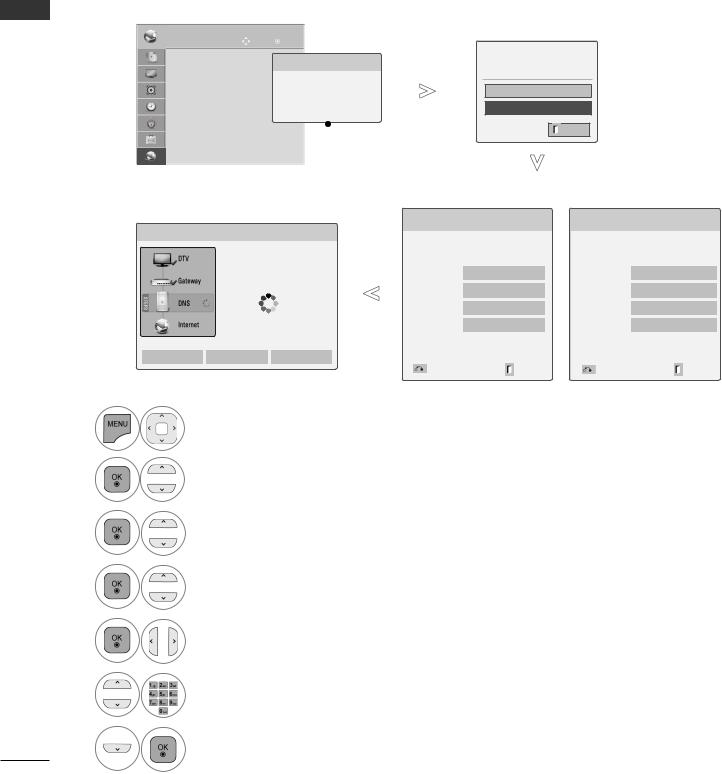
Wired Network Setup
If wired and wireless networks are both available, wired is the preferred method.
After making a physical connection, a small number of home networks may require the TV network settings to be adjusted.
For detail information, contact your internet provider or router manual.
|
NETWORK |
Move |
OK |
|||
|
• NetworkSetting |
:Wired |
Network Type |
|||
|
• |
: |
|
|
|
|
|
• Network Status |
:Internetis |
Wired network is recommended |
|||
|
• Legal Notice |
|
|
|
|
|
|
|
|
Wired |
|
||
|
|
|
|
|
||
|
|
|
|
|
|
|
|
|
|
|
Wireless |
|
|
|
|
|
|
|
|
|
|
|
|
|
|
Appeared when |
|
|
|
|
|
|
||
|
|
|
|
|
wired and wireless |
|
|
|
|
|
|||
|
|
|
|
|
are simultaneously |
|
|
|
|
|
|
connected. |
|
If you already set the Network Setting
Previous setting value exists. Do you want to connect with the previous setting?
|
OK |
|
Resetting |
Next |
Exit |
|
|
|
|
|
|
|
|
|
IP Auto Setting |
|
IP Manual Setting |
||||||||||||||||
|
|
|
|
|
|
|
|
Network Setting |
|
|
|
|
|
Network Setting |
|
|
|
|
|
|
|||||||
|
Network Setting |
|
|
|
|
|
|
|
|
|
|
|
|
|
|
|
|
|
|
|
|
|
|
|
|
||
|
|
|
|
|
|
|
|
Select the IP setting mode. |
Insert the IP address. |
|
|
|
|
|
|
||||||||||||
|
|
|
|
|
|
|
|
|
|
|
|
|
|
|
|
|
|
|
|
|
|
|
|
|
|
||
|
|
TV |
|
|
|
|
|
|
IP Mode |
◄ IP Auto Setting ► |
|
IP Mode |
◄ IP Manual Setting ► |
|
|||||||||||||
|
|
|
|
|
|
|
|
|
|
|
|
|
|
|
|
|
|
|
|
|
|
|
|
|
|
|
|
|
|
|
|
|
|
|
|
|
|
|
|
|
|
|
|
|
|
|
|
|
|
|
|
|
|
|
|
|
|
|
|
|
|
|
|
● IP Address |
|
0 |
. 0 . 0 . 0 |
|
● IP Address |
0 |
. 0 . 0 . 0 |
|
|
|
|||||||||
|
|
|
|
|
Network connecting |
|
|
|
|
|
|
|
|
|
|
|
|
|
|
|
|
|
|||||
|
|
|
|
|
|
|
|
|
|
|
|
|
|
|
|
|
|
|
|
|
|||||||
|
|
|
|
|
|
|
|
● Subnet Mask |
|
255 |
. 255 . 0 . 0 |
● Subnet Mask |
255 |
. 255 . 0 . 0 |
|
|
|
||||||||||
|
|
|
|
|
|
|
|
|
|
|
|
|
|
|
|
|
|
|
|
|
|
|
|
|
|
|
|
|
|
|
|
|
|
|
|
|
|
|
|
|
|
|
|
|
|
|
|
|
|
|
|
|
|
|
|
|
|
|
|
|
|
|
|
● Gateway |
|
0 |
. 0 . 0 . 0 |
|
● Gateway |
0 |
. 0 . 0 . 0 |
|
|
|
|||||||||
|
|
|
|
|
|
|
|
|
|
|
|
|
|
|
|
|
|
|
|
|
|
|
|
|
|
|
|
|
|
|
|
|
|
|
|
|
|
|
|
|
|
|
|
|
|
|
|
|
|
|
|
|
|
|
|
|
|
|
|
|
|
|
|
● DNS Server |
|
0 |
. 0 . 0 . 0 |
|
● DNS Server |
0 |
. 0 . 0 . 0 |
|
|
|
|||||||||
|
|
|
|
|
|
|
|
|
|
|
|
|
|
|
|
|
|
|
|
|
|
|
|
|
|
|
|
|
|
|
|
|
|
|
|
|
|
|
|
|
OK |
|
|
|
|
|
|
OK |
|
|
|
|
|
|
|
|
|
|
|
|
|
|
|
|
|
|
|
|
|
|
|
|
|
|
|
|
|
|
|
||||
|
Setting |
|
Test |
|
Close |
|
|
|
|
|
|
|
|
|
|
|
|
|
|
|
|
|
|
|
|
||
|
|
|
|
|
|
|
|
|
|
|
|
|
|
|
|
|
|
|
|
|
|
|
|
||||
|
|
|
|
|
|
|
|
|
Previous |
|
|
|
Exit |
|
Previous |
|
|
|
Exit |
|
|
|
|||||
|
|
|
|
|
|
|
|
|
|
|
|
|
|
|
|
|
|
|
|
|
|
|
|
|
|
|
|
Select NETWORK.
Select Network Setting.
Select Wired.
If you already set Network Setting: Select Resetting. The new connection settings resets the current network settings.
Select IP Auto Setting or IP Manual Setting.
When Selecting IP Manual Setting:
IP addresses will need to be input manually.
Select OK.
14

■■This feature requires an always-on broadband internet connection.
■■You do not need to connect to a PC to use this function.
■■If Network Setting is not working, check your network conditions. Check the LAN cable and make sure your router has DHCP turned on if you wish to use the Auto Setting.
■■ If the Network Setting is not completed, network may not operate normally.
■■IP Auto Setting: Select it if there is a DHCP server on the local area network (LAN) via wired connection, the TV will automatically be allocated an IP address. If you’re using a broadband router or broadband modem that has a DHCP (Dynamic Host Configuration Protocol) server function. The IP address will automatically be determined.
■■ IP Manual Setting: Select it if there is no DHCP server on the network and you want to set the IP address manually.
<![endif]>SETUP EQUIPMENT EXTERNAL
15

EXTERNAL EQUIPMENT SETUP
<![endif]>SETUP EQUIPMENT EXTERNAL
 NOTE
NOTE
►For more information about NetCast setup and troubleshooting, visit http://lgknowledgebase. com Search for NetCast.
►Use a standard LAN cable with this TV. Cat5 or better with a RJ45 connector.
►Many network connection problems during set up can often be fixed by re-setting the router or modem. After connecting the player to the home network, quickly power off and/or disconnect the power cable of the home network router or cable modem. Then power on and/or connect the power cable again.
►Depending on the internet service provider (ISP), the number of devices that can receive internet service may be limited by the applicable terms of service. For details, contact your ISP.
►LG is not responsible for any malfunction of the TV and/or the internet connection feature due to communication errors/malfunctions associated with your broadband internet connection, or other connected equipment.
►LG is not responsible for problems within your internet connection.
►Some content available through the network connection may not be compatible with the TV. If you have questions about such content, please contact the producer of the content.
►You may experience undesired results if the network connection speed does not meet the requirements of the content being accessed.
►Some internet connection operations may not be possible due to certain restrictions set by the Internet service provider (ISP) supplying your broadband Internet connection.
►Any fees charged by an ISP including, without limitation, connection charges are your responsibility.
►A 10 Base-T or 100 Base-TX LAN port is required for connection to this TV. If your internet service does not allow for such a connection, you will not be able to connect the TV.
►A DSL modem is required to use DSL service and a cable modem is required to use cable modem service. Depending on the access method of and subscriber agreement with your ISP, you may not be able to use the internet connection feature contained in this TV or you may be limited to the number of devices you can connect at the same time. (If your ISP limits sub-scription to one device, this TV may not be allowed to connect when a PC is already connected.)
►The use of a “Router” may not be allowed or its usage may be limited depending on the policies and restrictions of your ISP. For details, contact your ISP directly.
►The wireless network operates at 2.4 GHz radio frequencies that are also used by other household devices such as cordless telephone, Bluetooth® devices, microwave oven, and can be affected by interference from them.It can be interrupted by the device using 5 GHz radio frequencies. It is same device with LG wireless media box, cordless telephone, other Wi-Fi device.
►It may decrease the service speed using Wireless network by surrounding wireless condition.
►Turn off all unused network equipment in your local home network. Some devices may generate network traffic.
►In some instances, placing the access point or wireless router higher up away from the floor may improve the reception.
►The reception quality over wireless depends on many factors such as type of the access point, distance between the TV and access point, and the location of the TV.
►When connecting internet through the wired/
wireless sharing machine, it may interrupt the connection because of the use limitation and confirmation of service company.
►To connect wireless AP, an AP that supports the wireless connection is necessary, and the wireless connection function of the AP needs
to be activated. Please enquire to the AP
supplier for the possibility of AP wireless connections.
►►Please verify the security settings of AP SSID for
wireless AP connection, and enquire to the AP supplier for the AP SSID security settings.
►►The TV can become slower or malfunction with wrong settings of network equipments (wired/
wireless router, hub, etc). Please install correctly by referring to the manual of the equipment, and set the network.
►When► AP is set to include 802.11n, and if Encryption is designated as WEP(64/128bit) or WPA(TKIP/AES), the connection may not be possible.
►There► may be different connection methods according to the AP manufacturers.
16
Loading...