

LG 47VL10-BAA Owner’s Manual
<![endif]>ENGLISH
OWNER’S MANUAL
MONITOR SIGNAGE
Please read this manual carefully before operating the your set and retain it for future reference.
MONITOR SIGNAGE MODEL
47VL10
www.lg.com

<![endif]>ENGLISH
2 TABLE OF CONTENTS
TABLE OF CONTENTS
3 |
LICENSES |
|
26 MAKING CONNECTIONS |
|||
|
|
|
|
|
||
|
|
|
27 Connecting to a HD receiver, DVD, |
|||
4 |
ASSEMBLING AND |
|
|
|
Camcorder, Camera, Gaming Device or |
|
|
|
|
VCR player |
|||
|
PREPARING |
|
|
|
||
|
|
27 |
- HDMI connection |
|||
4 |
Accessories |
|||||
27 |
- HDMI/DVI connection |
|||||
5 |
Optional Accessories |
|||||
28 |
- AV(CVBS) connection |
|||||
6 |
Parts and buttons |
|||||
|
|
|
|
|||
7 |
Connecting the stand |
|
|
29 TROUBLESHOOTING |
||
7 |
Connecting the Speakers |
|
|
|||
|
||||||
8 |
Cable Management |
|
|
|
|
|
9 |
Connecting stand hole cover |
|
32 SPECIFICATIONS |
|||
9 |
To install Portrait |
|
||||
|
|
|
|
|||
10 |
Installing on a wall |
|
35 RS-232C |
|||
11 |
|
|
||||
REMOTE CONTROL |
35 |
Connecting the cable |
||||
|
|
35 |
RS-232C Configurations |
|||
12 |
USING THE MONITOR SET |
35 |
Communication Parameter |
|||
36 |
Command reference list |
|||||
12 |
Connecting to a PC |
|||||
38 |
Transmission / Receiving protocol |
|||||
12 |
- Using the input list |
47 |
IR CODES |
|||
13 |
- RGB connection |
|
|
|
|
|
13- HDMI/DVI connection
14- HDMI connection
14- LAN connection
15CUSTOMIZING SETTINGS
15Accessing main menus
16- PICTURE settings
20- AUDIO settings
21- TIME settings
22- OPTION settings
25- INFORMATION settings

LICENSES 3
LICENSES
Supported licenses may differ by model. For more information of the licenses, visit www.lg.com.
The terms HDMI and HDMI High-Definition Multimedia Interface, and the HDMI logo are trademarks or registered trademarks of HDMI Licensing LLC in the United States and other countries.
<![endif]>ENGLISH
<![endif]>ENGLISH
4 ASSEMBLING AND PREPARING
ASSEMBLING AND PREPARING
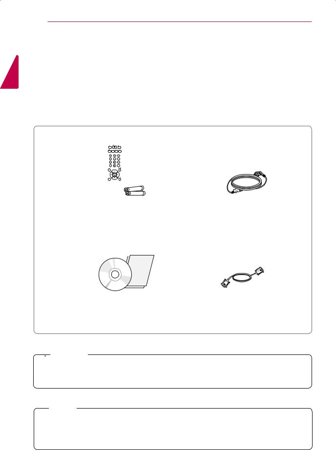
Accessories
Check your product box for the following items. If there are any missing accessories, contact the local dealer where you purchased your product. The illustrations in this manual may differ from the actual product and accessories.
|
|
|
Power Cord |
Remote control and Batteries |
|||
User Manual/Card |
15-pin D-SUB Signal Cable |
 CAUTION
y yDo not use any pirated items to ensure the safety and product life span.
y yAny damages or injuries by using pirated items are not covered by the warranty.
 NOTE
NOTE
y yThe accessories supplied with your product may vary depending on the model.
y yProduct specifications or contents in this manual may be changed without prior notice due to upgrade of product functions.
ASSEMBLING AND PREPARING 5
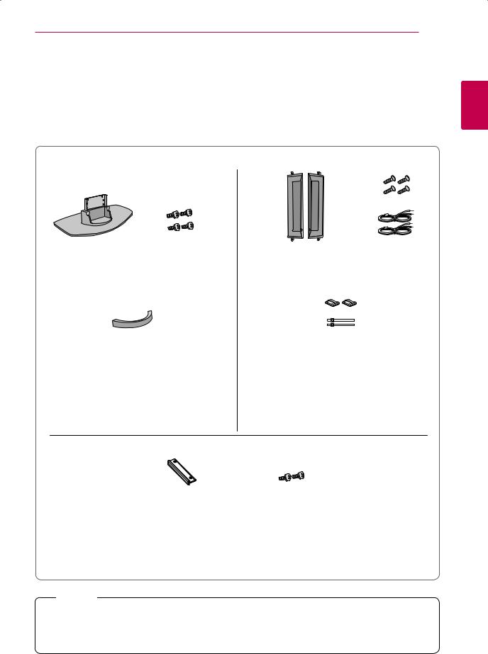
Optional Accessories
Without prior notice, optional accessories are subject to change to improve the performance of the product, and new accessories may be added. The illustrations in this manual may differ from the actual product and accessories.
<![endif]>ENGLISH
Stand |
Screws |
Speaker |
Screws/Cable |
|
cable management |
Cable holder/ |
|
Cable Tie |
Stand kit Speaker kit
Stand hole cover |
Screws |
Stand hole cover kit
 NOTE
NOTE
y yCable holder/Cable tie may not be available in some areas or for some models. y yOptional accessories are not included for all models.
6 ASSEMBLING AND PREPARING
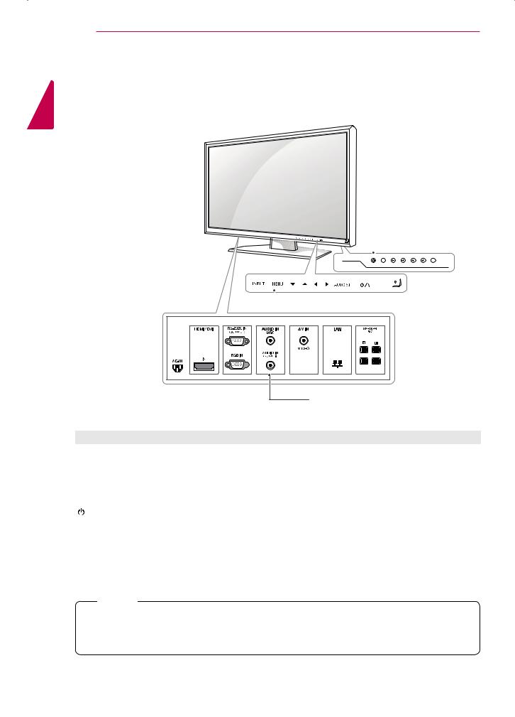
Parts and buttons
<![if ! IE]><![endif]>ENGLISH

 Screen Buttons
 Screen Marks
Connection panel |
Screen Marks |
Description |
INPUT |
Changes the input source. |
|
|
MENU |
Accesses the main menus, or saves your input and exits the menus. |
▼▲ |
Adjust the up and down. |
◄ ► |
Adjusts the volume level. |
|
|
AUTO/SET |
For optimal screen display, automatically adjusts screen resolution. |
|
|
/ I |
Turns the power on or off. |
IR Receiver |
This is where the unit receives signals from the remote control. |
|
|
Power Indicator |
This Indicator lights up blue when the display operates normally(on mode). If the display |
|
is in sleep (Energy Saving) mode, this indicator color changes to amber. |
 NOTE
NOTE
y yYou can set the Power indicator to on or off by selecting OPTION in the main menus.

ASSEMBLING AND PREPARING 7
Connecting the stand
- Only on some models.
1 Take the parts for the stand out of the box and assemble them as shown in the picture.
Connecting the Speakers
- Only on some models.
1Mount the product onto the speaker by using a screw as shown in the following connect the speaker cable.
<![endif]>ENGLISH
Stand Screws
cable management
2Place a soft cloth on the table and put the product with the screen facing downward. Connect the stand as shown in the following picture.
3Use the screws to secure the stand on the rear side of the product as shown in the diagram.
2After installing your speakers, use holders and cable ties to organize the speaker cables. (This feature is not available in all model.)
 NOTE
NOTE
y yConnect the speaker terminals noting the correct polarity.
<![endif]>ENGLISH
8 ASSEMBLING AND PREPARING
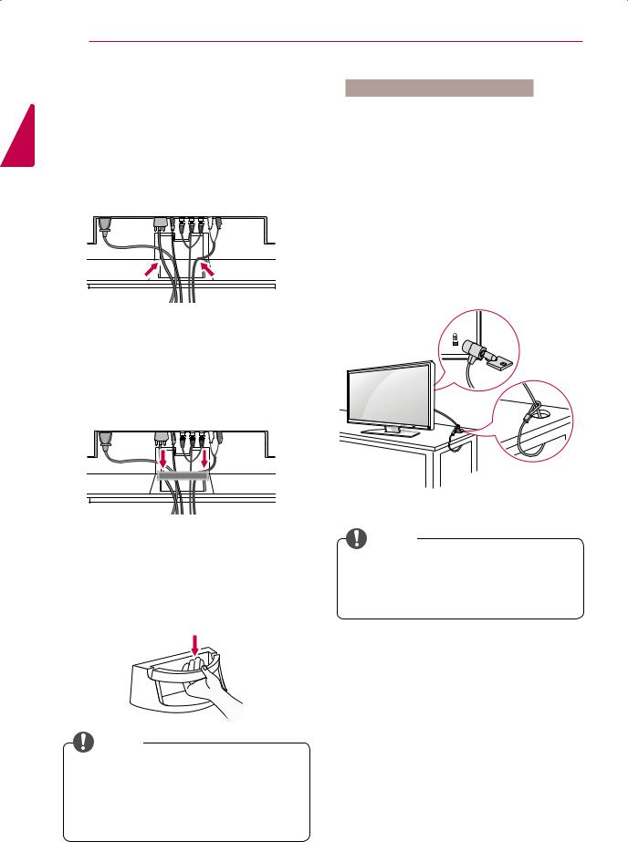
Cable Management
- Only on some models.
1Arrange the cables in the center as shown in the following picture.
Using the Kensington security system
The Kensington security system connector is located at the back of the Monitor set. For more information of installation and using, refer to the manual supplied with the Kensington security system or visit http://www.kensington.com.
Connect the Kensington security system cable between the Monitor set and a table.
2Fit the cable management to the back to help manage the cables.
3For removing the cable management, hold the Cable management with both hands and pull it downward.
 NOTE
NOTE
y yDo not use the cable management as a handle for the Monitor.
y yThe illustrations in this manual may differ from actual cable interfaces.
 NOTE
NOTE
y yThe Kensington security system is optional. You can obtain additional accessories from most electronics stores.
ASSEMBLING AND PREPARING 9
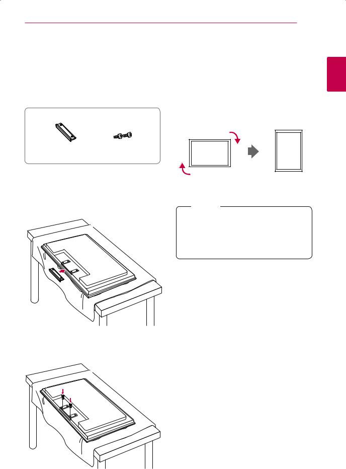
Connecting stand hole cover
- Only on some models.
1 Take the parts for the stand out of the box and assemble them as shown in the picture.
To install Portrait
- Only on some models.
When installing Portrait, rotate it clockwise based on its front.
<![endif]>ENGLISH
Stand hole cover |
Screws |
2Place a soft cloth on the table and put the product with the screen facing downward. Connect the stand hole cover as shown in the following picture.
3Use the screws to secure the stand hole cover on the rear side of the product as shown in the diagram.
 NOTE
NOTE
y yWhen using the wall mounting bracket or the portrait scene mode, the opening can be covered by the stand hole cover.
<![endif]>ENGLISH
10 ASSEMBLING AND PREPARING
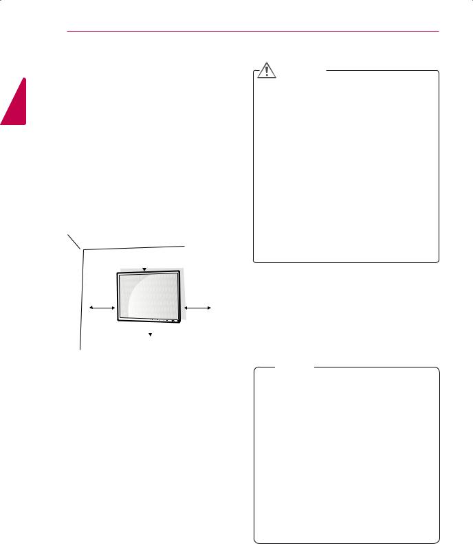
Installing on a wall |
|
CAUTION |
Install the monitor at least 10 cm away from the wall and leave about 10 cm of space at each side of the monitor to ensure sufficient ventilation. Detailed installation instructions can be obtained from your local retail store. Please refer to the manual to install and set up a tilting wall mounting bracket.
 10 cm
10 cm
10 cm |
10 cm |
 10 cm
10 cm
y yDisconnect the power cord first, and then move or install the Monitor set. Otherwise electric shock may occur.
y yIf you install the Monitor set on a ceiling or slanted wall, it may fall and result in severe injury. Use an authorized LG wall mount and contact the local dealer or qualified personnel.
y yDo not over tighten the screws as this may cause damage to the Monitor set and void your warranty.
y yUse the screws and wall mounts that meet the VESA standard. Any damages or injuries by misuse or using an improper
accessory are not covered by the warranty.
If you want to mount the monitor on the wall (optional), attach the wall mounting bracket to the rear of the monitor.
Make sure that the wall mounting bracket is securely fixed to the monitor and to the wall.
Use the wall mount plate and screws that comply with the VESA standard as specified below.
y y785mm(31 inch) or greater
*Fastening screw: Diameter 6.0 mm x Pitch 1.0 mm x Length 10 mm
(32 inch is Diameter 4.0 mm x Pitch 0.7 mm x Length 10 mm)
 NOTE
NOTE
y yUse the screws that are listed on the VESA standard screw specifications.
y yThe wall mount kit includes an installation manual and necessary parts.
y yThe wall mount bracket is optional. You can obtain additional accessories from your local dealer.
y yThe length of screws may differ depending on the wall mount. Be sure to use the proper length.
y yFor more information, refer to the instructions supplied with the wall mount.
REMOTE CONTROL 11
REMOTE CONTROL
The descriptions in this manual are based on the buttons of the remote control. Please read this manual carefully and use the Monitor set correctly. To replace batteries, open the battery cover, replace batteries (1.5 V AAA) matching  and
and  ends to the label inside the compartment, and close the battery cover. To remove the batteries, perform the installation actions in reverse.
CAUTION
y yDo not mix old and new batteries, as this may damage the remote control.
Make sure to point the remote control to the remote control sensor on the Monitor set.
 (POWER)
Turns the Monitor set on or off.
AV
Toggles through video.
AV -> RGB PC -> HDMI/DVI
Sleep
When watching AV, RGB PC,HDMI/DVI.The product will be automatically turned off after a certain period of time.
Press this button repetitively to select an appropriate time
duration.
PSM
Toggles through preset video settings.
Menu
UP and Down
Bring up and down direction adjustment.
Mute
INPUT
Selects the input mode.
ARC
Aspect Ratio Correction. Toggles through aspect ratio options.
Auto
Automatic adjustment function (Operational for the analog signal only)
There is not a function which is supported
Exit
Volume ◄ ►
Volume up and down.
Check
There is not a function which is supported.
<![endif]>ENGLISH
<![endif]>ENGLISH
12 USING THE MONITOR SET
USING THE MONITOR SET
Connecting to a PC
Your Monitor set supports the Plug & Play* feature .
* Plug & Play: The function when a PC recognizes a connected device that users connect to a PC and turn on, without device configuration or user intervention.
 NOTE
NOTE
y yIt is recommended to use the Monitor set with the HDMI connection for the best image quality.
y yUse a shielded signal interface cable, such as D-sub 15 pin signal cable and DVI/HDMI cable, with a ferrite core to maintain standard compliance for the product.
y yIf you turn the Monitor set on when the set becomes cold, the screen may flicker. This is normal.
y ySome red, green, or blue spots may appear on the screen. This is normal.
Using the input list
Selecting an input source
1Press INPUT to access the input source list.
-The connected device displays on each input source.
2Press the Navigation buttons to scroll to one of the input sources and press OK.
Input source |
Description |
|
|
AV |
Watch the contents in a VCR or |
|
other external devices |
|
|
RGB-PC |
View a PC display on the screen |
|
|
HDMI/DVI |
Watch contents in a PC, DVD |
|
or Digital settop box other high |
|
definition devices |
|
|
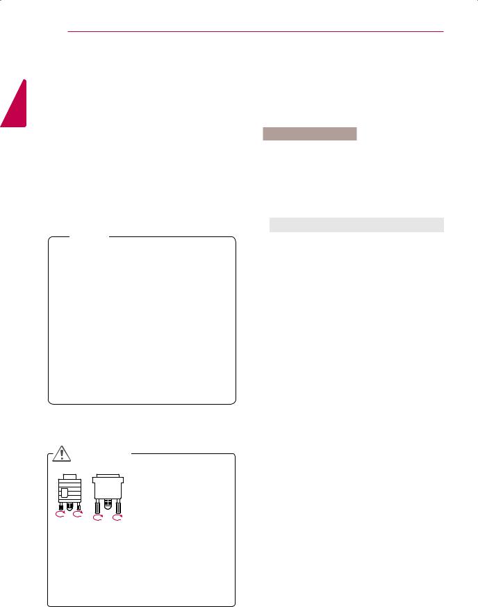
CAUTION
y yConnect the signal input cable and tighten it by turning the screws clockwise.
y yDo not press the screen with your finger for a long time as this may result in temporary distortion on the screen.
y yAvoid displaying a fixed image on the screen for a long period of time to prevent image burn. Use a screensaver if possible.
USING THE MONITOR SET 13
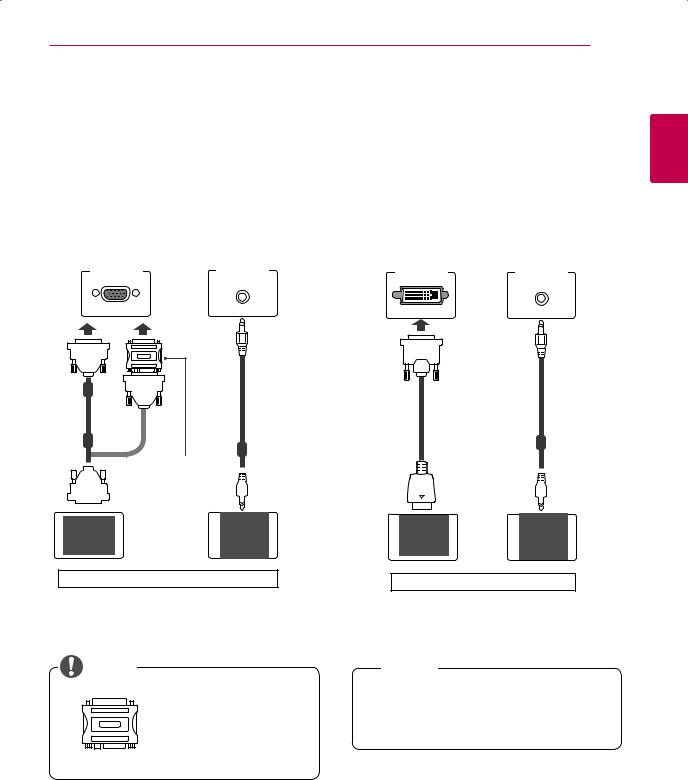
RGB connection
Transmits the analog video signal from your PC to the Monitor set. Connect the PC and the Monitor set with the D-sub 15 pin cable as shown the following illustrations.
Select RGB input source.
HDMI/DVI connection
Transmits the digital video signal from your PC to the Monitor set. Connect the PC and the Monitor set with the HDMI/DVI cable as shown the following illustrations.
Select HDMI/DVI input source.
PC/MAC |
PC |
PC |
PC |
<![endif]>ENGLISH
(not included) |
(not included) |
(not included) |
|
Macintosh Adapter (not included)
Back of the Monitor Set |
Back of the Monitor Set |
NOTE
y yUse the standard Macintosh adapter since an incompatible adapter is available in the market. (Different signaling system)
 NOTE
NOTE
y yWhen HDMI PC is used, a compatiblity problem might occur.
<![endif]>ENGLISH
14 USING THE MONITOR SET
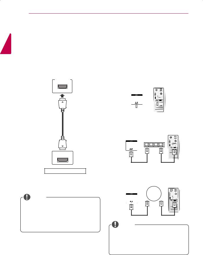
HDMI connection
Transmits the digital video and audio signals from your PC to the Monitor set. Connect the PC and the Monitor set with the HDMI cable as shown in the following illustrations.
Select HDMI/DVI input source.
PC
(not included)
HDMI/DVI IN
LAN connection
Connect the LAN cable and install the eZ-Net Manager program on the CD-ROM.
For more information about the program, please refer to eZ-Net Guide in the enclosed CD-ROM.
A Connect PC to Monitor directly.
LAN
Monitor Set |
|
|
|
PC |
||||
|
|
|
||||||
|
|
|
||||||
|
|
|
|
|
|
|
|
|
|
|
|
|
|
|
|
|
|
|
|
|
|
|
|
|
|
|
|
|
|
|
|
|
|
|
|
|
|
|
|
|
|
|
|
|
B Using a router(Switch)
LAN Switch
Monitor Set |
PC |
Back of the Monitor Set |
|
|
|
|
C Using the Internet. |
|
|
|
LAN |
Network |
|
NOTE |
|
|
|
Monitor Set |
|
PC |
|
y yUse a High Speed HDMI™ Cable. |
|
|
|
y yPlease check the PC environment if you |
|
|
|
cannot hear the sound in HDMI mode. |
|
|
|
y yIf you want to use HDMI-PC mode, you must |
|
|
|
set the input label to PC mode. |
NOTE |
|
|
|
y yUsing LAN establishes communication |
|
|
|
between your PC and the monitor and |
|
|
|
enables to use the OSD menus on the PC as |
||
|
well as on the monitor. |
|
|
CUSTOMIZING SETTINGS 15
CUSTOMIZING SETTINGS
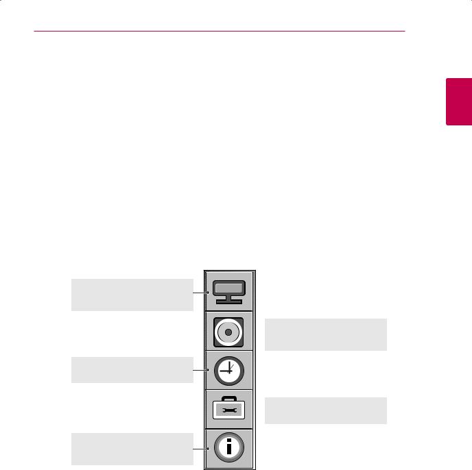
Accessing main menus
1Press MENU to access the main menus.
2Press the Navigation buttons to scroll to one of the following menus and press SET.
3Press the Navigation buttons to scroll to the setting or option you want and press SET.
4When you are finished, press EXIT.
<![endif]>ENGLISH
PICTURE ( See p.16 )
Adjusts the image size, quality, or effect
AUDIO ( See p.20 )
 Adjusts the sound quality, effect, or volume level
TIME ( See p.21 )
Sets the time, date or Timer feature
OPTION ( See p.22 )
 Customizes the general settings
INFORMATION ( See p.25 )
Adjust Set ID and check Serial No. and SW version.
 Loading...