

LG 52LD550, 32LD450, 22LD350, 19LD350, 46LD550 Owner's Manual
...
ENGLISH
OWNER’S MANUAL
LCD TV / LED LCD TV
Please read this manual carefully before operating
your set and retain it for future reference.
www.lg.com
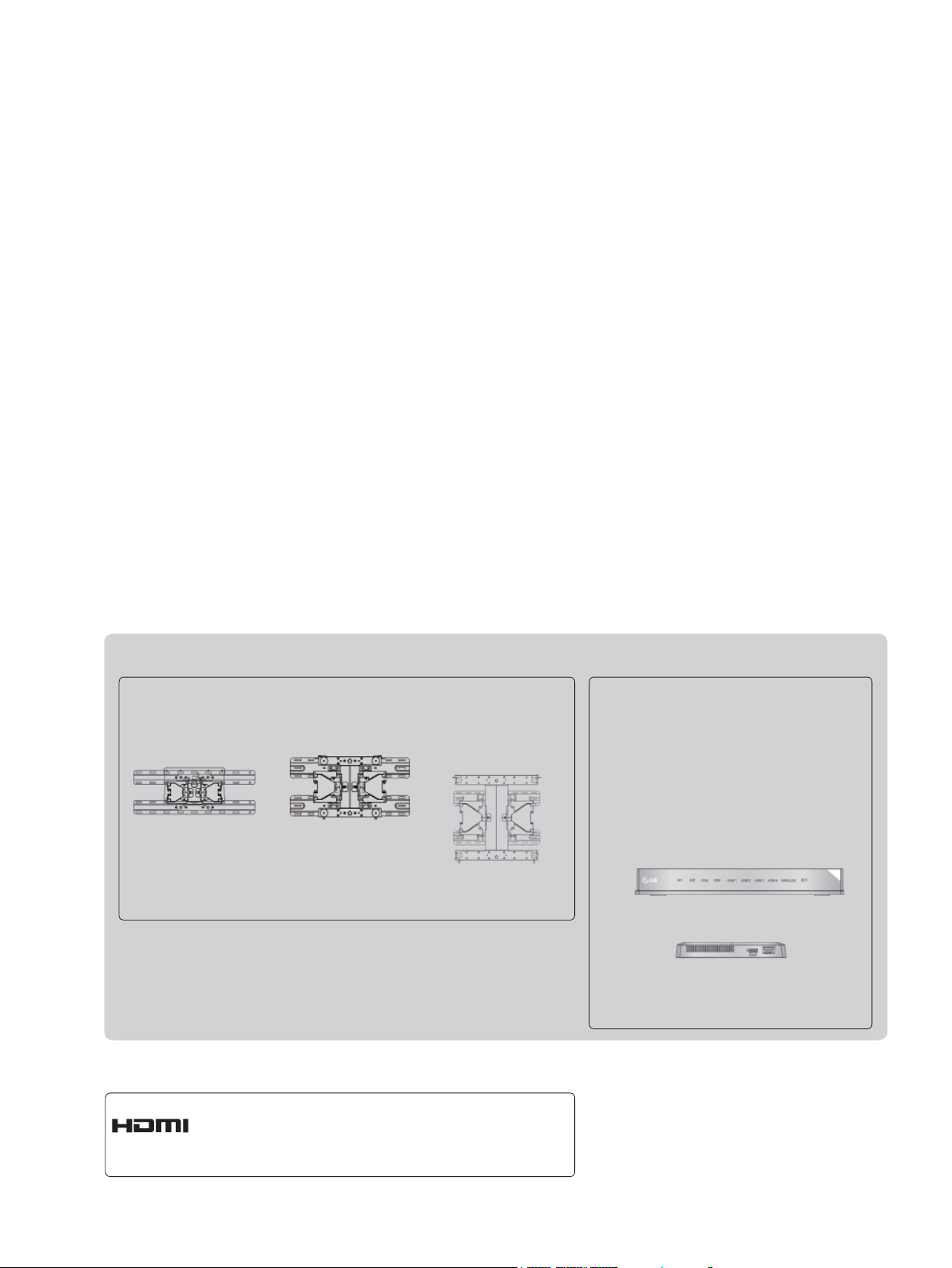
Separate purchase
Wall Mounting Bracket
LSW100B or
LSW100BG
(19/22/26/32LD3
32LD4
, 32LD5
***
19/22/26/32LE3
32LE4
, 22/26LE5
***
32LE5
***
***
***
***
***
,
,
,
,
)
HDMI, the HDMI logo and High-Definition
Multimedia Interface are trademarks or registered trademarks of HDMI Licensing LLC.
LSW200B or
LSW200BG
(37/42/47LD4
42/46LD5
37/42LE4
37/42/47LE5
***
***
***
***
LSW400B or
LSW400BG or
DSW400B or
DSW400BG
,
,
,
)
(52/60LD5
55LE5
***
***
Optional extras can be changed or
modified for quality improvement
without any notification.
Contact your dealer for buying these
items.
This device only works with compatible
LG LED LCD TV or LCD TV.
Wireless Media Box
,
)
(32/42/46/52/60LD5
32LE3
, 32/37/42LE4
***
32/37/42/47/55LE5
***
***
,
,
***
)

CONTENTS
PREPARATION
LCD TV Models : 19/22/26/32LD35
19/22/26/32LD34
LCD TV Models : 32/37/42/47LD4
26/32LD33
LCD TV Models : 32/42/46/52/60LD5
LED LCD TV Models : 19/22/26/32LE3
42LE4
** ........................................................... A-14
, 22/26LE5
***
** .......................................... A-1
32/37/42/47/55LE5
***,
**,
, 26/32LD32**
***
*** ...... A-24
, 32/37/
***
*** ...... A-33
EXTERNAL EQUIPMENT SETUP
Antenna Connection ............................................1
Connecting with a Component cable ..................2
Connecting with an HDMI cable .........................3
Connecting with an HDMI to DVI cable ..............4
Connecting with a Euro Scart cable ...................5
USB setup ...........................................................6
Connecting with a RF Cable ...............................6
Connecting with a RCA cable .............................7
Connecting with a D-sub 15 pin cable ................8
Insertion of CI Module .........................................9
Headphone Setup ...............................................9
Digital audio out Setup ......................................10
External Equipment WIreless Connection ........ 11
Supported Display Resolution ...........................12
Screen Setup for PC mode ...............................13
WATCHING TV / PROGRAMME CONTROL
Product/service information...............................39
Simple Manual ..................................................40
Selecting the Programme List ...........................41
Input List ............................................................43
Input Label ........................................................44
Data Service ......................................................45
SIMPLINK ..........................................................46
AV Mode ............................................................50
Initializing(Reset to original factory settings) ....51
TO USE A USB DEVICE
When connecting a USB device .......................52
Movie list ..........................................................54
Photo list ............................................................65
Music list ............................................................75
DivX Registration Code ....................................84
Deactivation .....................................................85
EPG(ELECTRONIC PROGRAMME
GUIDE)(IN DIGITAL MODE)
Switch on/off EPG .............................................87
Select a programme ..........................................87
Button Function in NOW/NEXT Guide Mode ...87
Button Function in 8 Day Guide Mode .............88
Button Function in Date Change Mode ............89
Button Function in Extended Description Box ..89
Button Function in Record/Remind Setting Mode 90
Button Function in Schedule List Mode ............91
CONTENTS
Turning on the TV .............................................17
Initializing Setup ...............................................17
Programme Selection ........................................17
Volume Adjustment ...........................................17
Quick Menu .......................................................18
On Screen Menus Selection and adjustment ...19
Auto programme tuning ...................................20
Cable DTV setting .............................................25
Manual programme Tuning ...............................26
Programme Edit ...............................................30
CI [Common Interface] Information ...................34
Software Update ...............................................35
Picture/Sound test .............................................37
Diagnostics ........................................................38
I

CONTENTS
PICTURE CONTROL
Picture Size (Aspect Ratio) Control ..................92
CONTENTS
Picture Wizard ...................................................94
Energy Saving ...................................................95
Preset Picture Settings .....................................96
Manual Picture Adjustment ...............................97
Picture Improvement Technology ......................98
Expert Picture Control .......................................99
Picture Reset ...................................................102
Trumotion ........................................................103
Power Indicator ..............................................104
Mode Setting ...................................................105
Demo Mode .....................................................106
SOUND & LANGUAGE CONTROL
Auto Volume Leveler .......................................107
Clear Voice II ...................................................108
Preset Sound Settings-Sound Mode ..............109
Sound Setting Adjustment -User Mode ..........110
Infinite Sound ..................................................110
Balance ........................................................... 111
TV Speakers On/ Off Setup ............................112
DTV Audio Setting (in digital mode only) ........ 113
Selecting Digital Audio out ..............................114
Audio Reset ..................................................... 115
Audio Description (In digital mode only) ......... 116
I/II
Stereo/Dual Reception (In Analogue Mode Only) 117
-
- NICAM Reception (In Analogue Mode Only) 118
- Speaker Sound Output Selection ................118
On-Screen Menu Language / Country Selection 119
Language Selection ........................................120
PARENTAL CONTROL / RATINGS
Set Password & Lock System.........................125
Block Programme ............................................126
Parental Control (In Digital Mode only) ...........127
External Input Blocking ...................................128
Key Lock..........................................................129
TELETEXT
Switch on/off ...................................................130
SIMPLE Text....................................................130
TOP Text..........................................................131
FASTEXT ........................................................131
Special Teletext Functions ..............................132
DIGITAL TELETEXT
Teletext within Digital Service .........................133
Teletext in Digital Service ................................133
APPENDIX
Troubleshooting ...............................................134
Maintenance ....................................................136
Product Specifications .....................................137
IR Codes .........................................................148
External Control Device Setup ........................149
Open source software notice ..........................156
II
TIME SETTING
Clock Setup .....................................................122
Auto on/off time setting ...................................123
Sleep Timer setting .........................................124
PREPARATION
LCD TV MODELS :
19/22/26/32LD35**, 19/22/26/32LD34
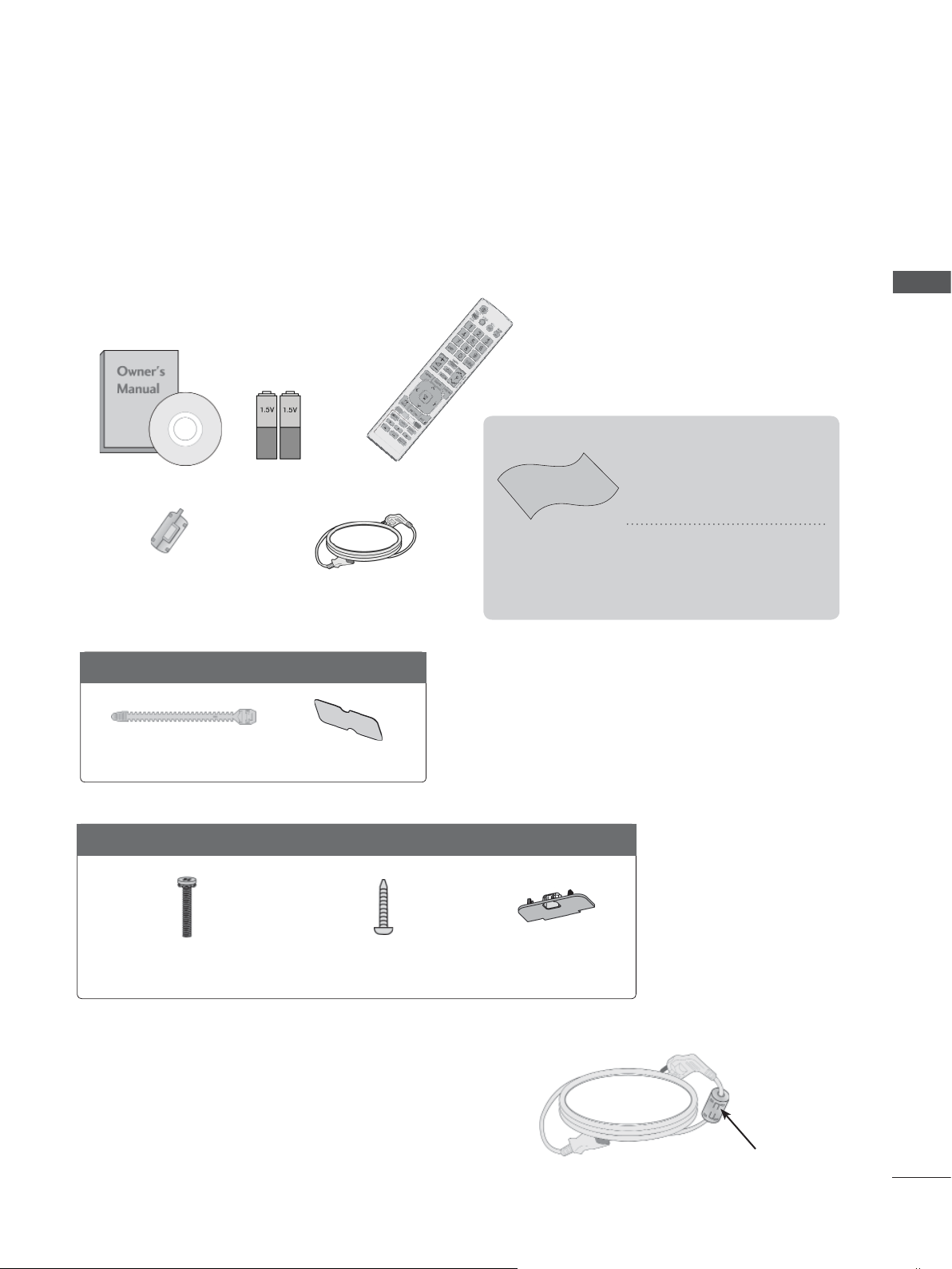
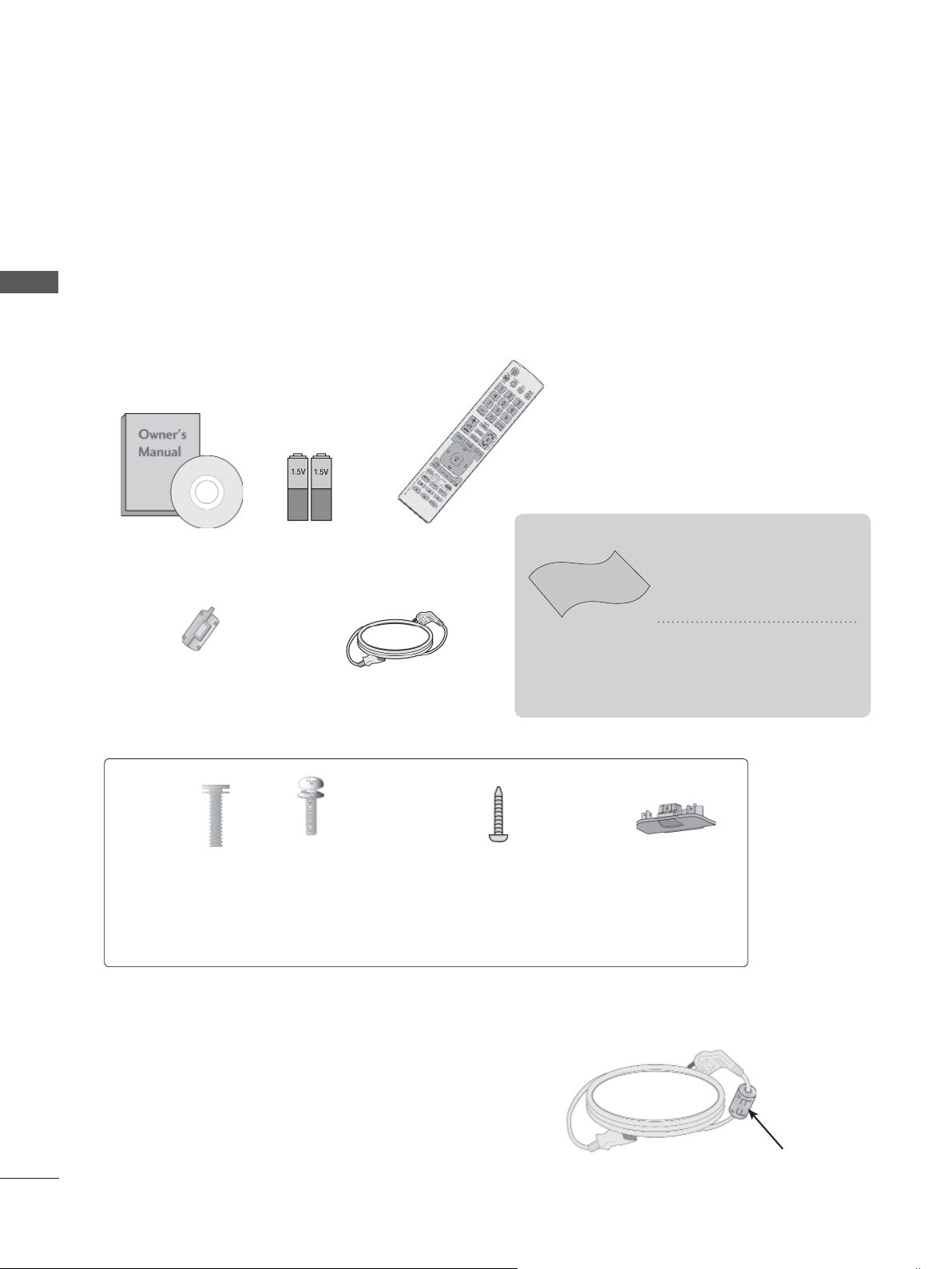
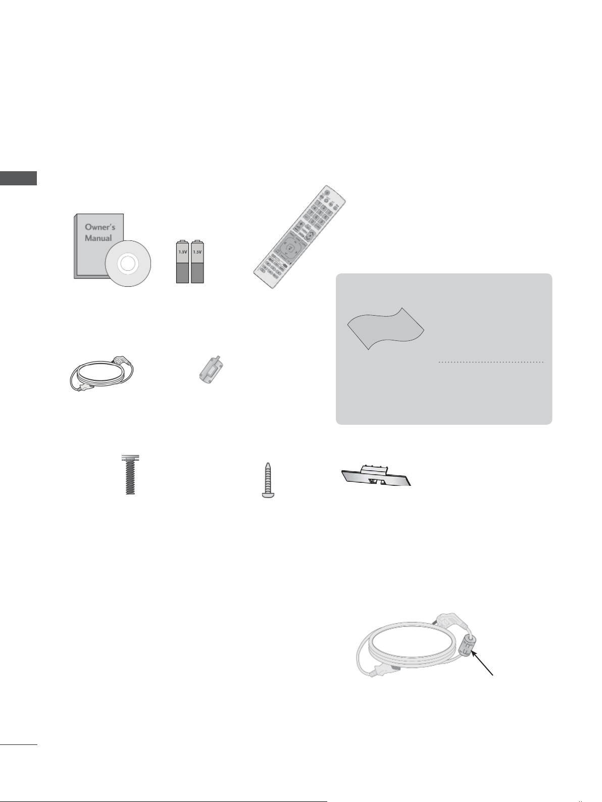
ACCESSORIES
Ensure that the following accessories are included with your TV. If an accessory is missing, please
contact the dealer where you purchased the TV.
■ Image shown may differ from your TV.
This item is not included for all models.
* Lightly wipe any stains or
Owner’s Manual Batteries
Ferrite Core
(
This item is not included
for all models.
(AAA)
)
Remote Control
Polishing Cloth
Polishing cloth for
use on the screen.
Power Cord
fingerprints on the surface
of the TV with the polishing cloth.
Do not use excessive
force. This may cause
scratching or discolouration.
**
PREPARATION
Only 19/22LD35**, 19/22LD34
Cable Holder
Only 26/32LD35**, 26/32LD34
x 8
(M4x20)
Bolts for stand assembly
**
Protection Cover
**
1-screw for stand fixing
Protection Cover
Use of ferrite core (This feature is not available for all models.)
Ferrite core can be used to reduce the electromagnetic
wave when connecting the power cord.
The closer the location of the ferrite core to the power
plug, the better it is.
Install the power plug closely.
A-1
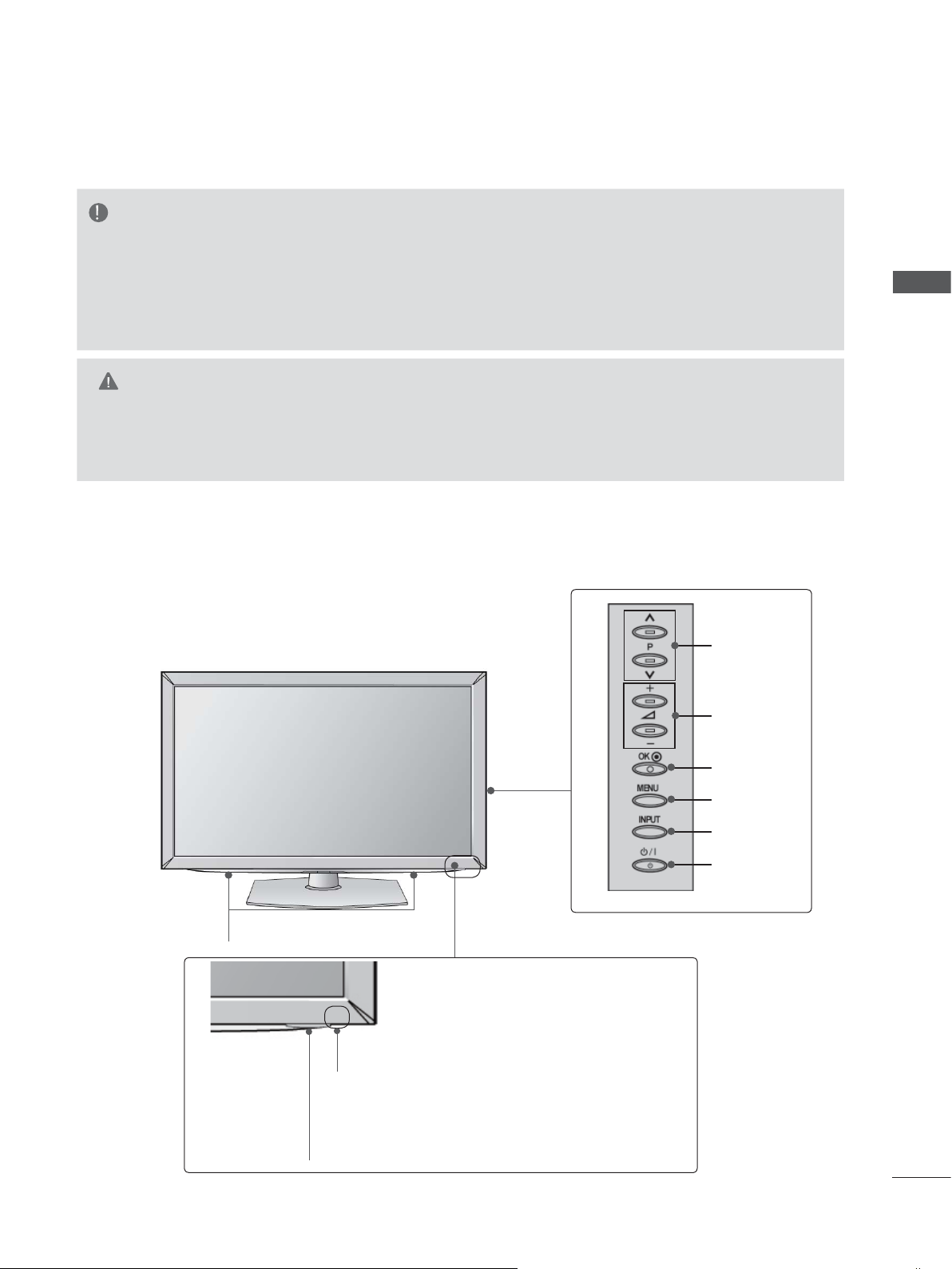
PREPARATION
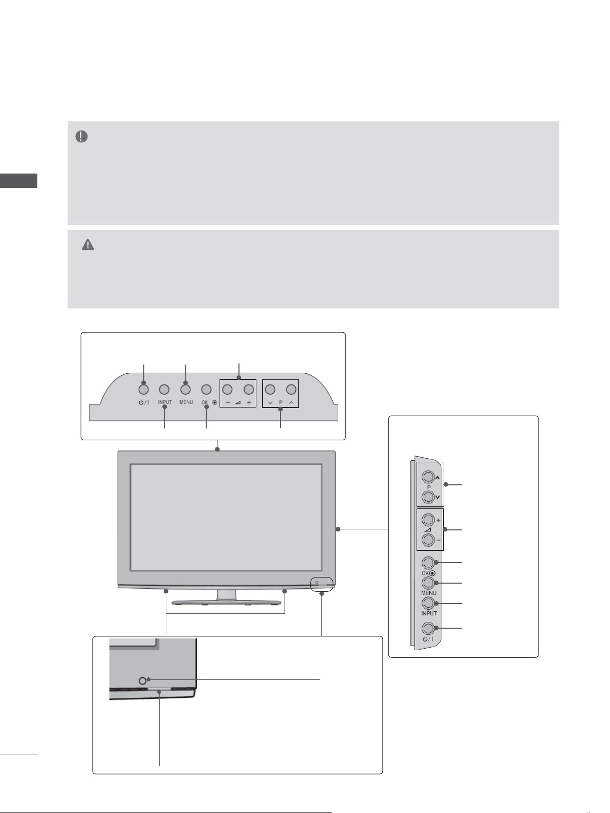
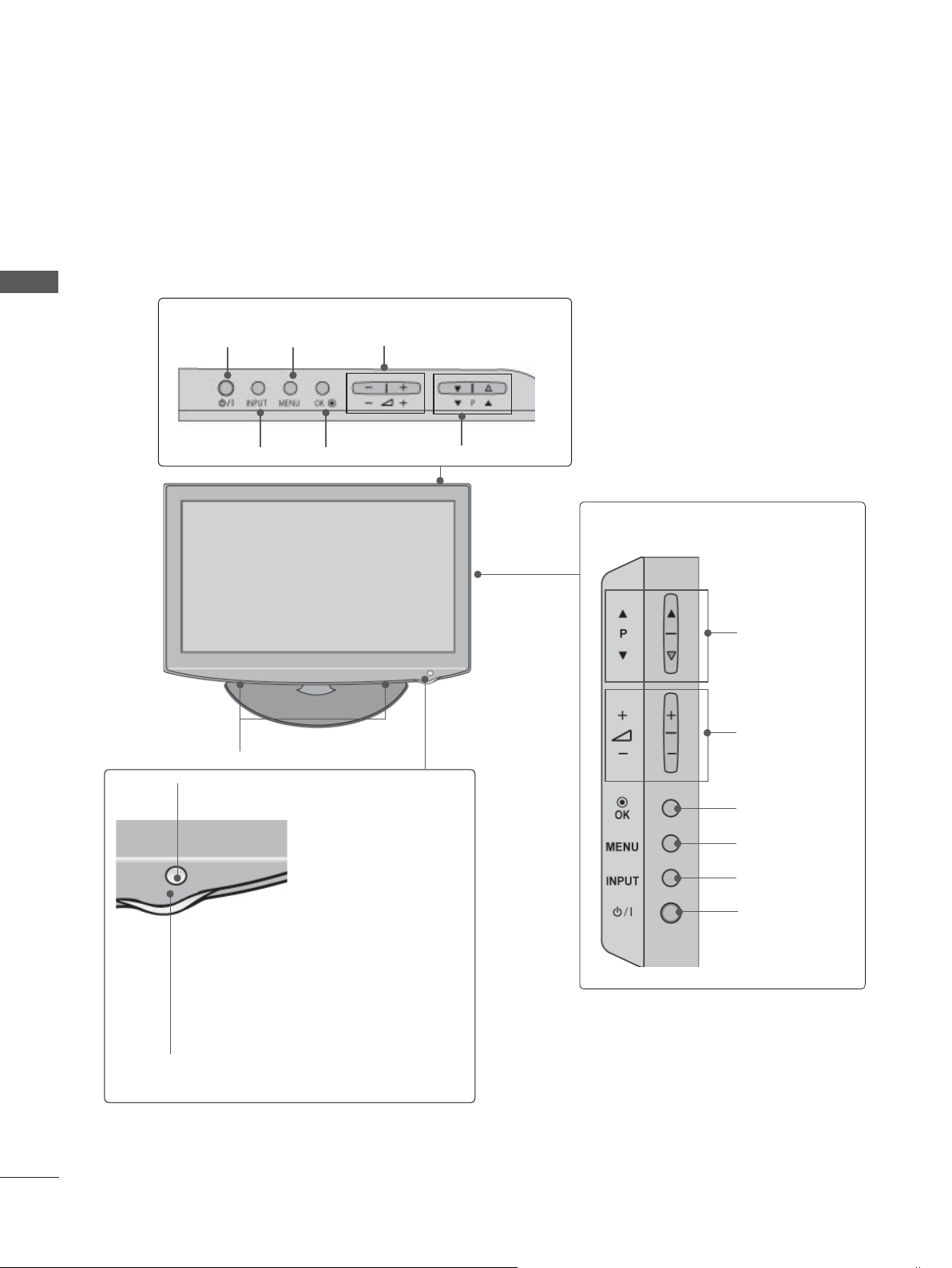
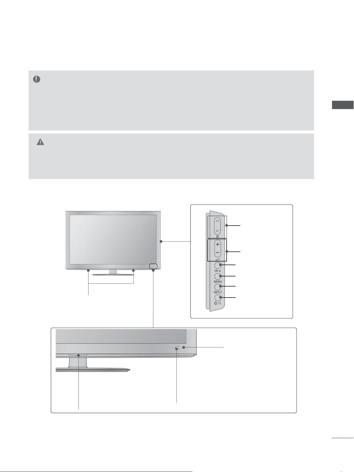
FRONT PANEL CONTROLS
NOTE
►TV can be placed in standby mode in order to reduce the power consumption. And TV should be
switched off using the power switch on the TV if it will not be watched for some time, as this will
PREPARATION
reduce energy consumption.
►The energy consumed during use can be significantly reduced if the level of brightness of the
picture is reduced, and this will reduce the overall running cost.
CAUTION
►Do not step on the glass stand or subject it to any impact. It may break, causing possible injury
from fragments of glass, or the TV may fall.
►Do not drag the TV. The floor or the product may be damaged.
■ Image shown may differ from your TV.
Only 19/22LD35**, 19/22LD34**
MENUPOWER
VOLUME
OKINPUT
SPEAKER
Remote Control Sensor
PROGRAMME
Only 26/32LD35**,
26/32LD34
**
PROGRAMME
VOLUME
OK
MENU
INPUT
POWER
A-2
Power/Standby Indicator
• Illuminates red in standby mode.
• Illuminates blue when the TV is switched on.
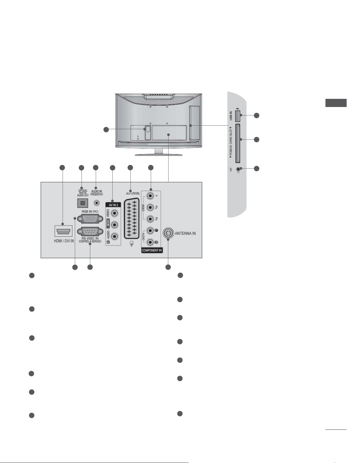
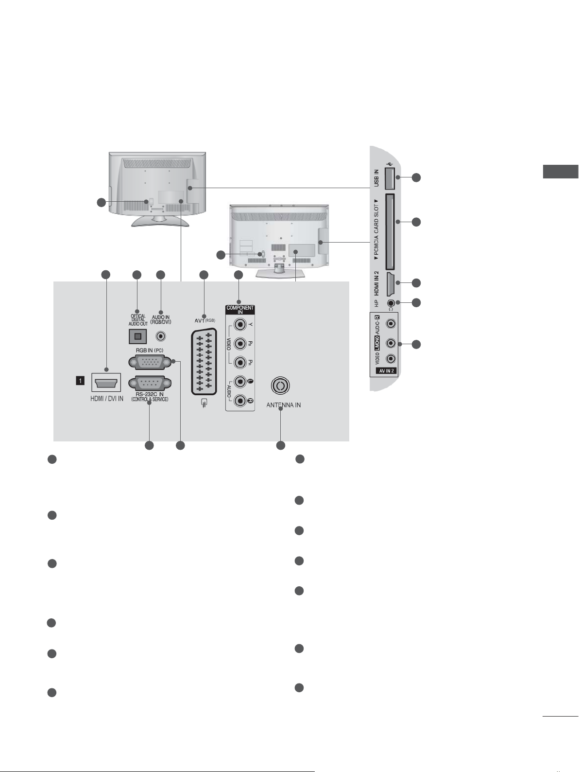
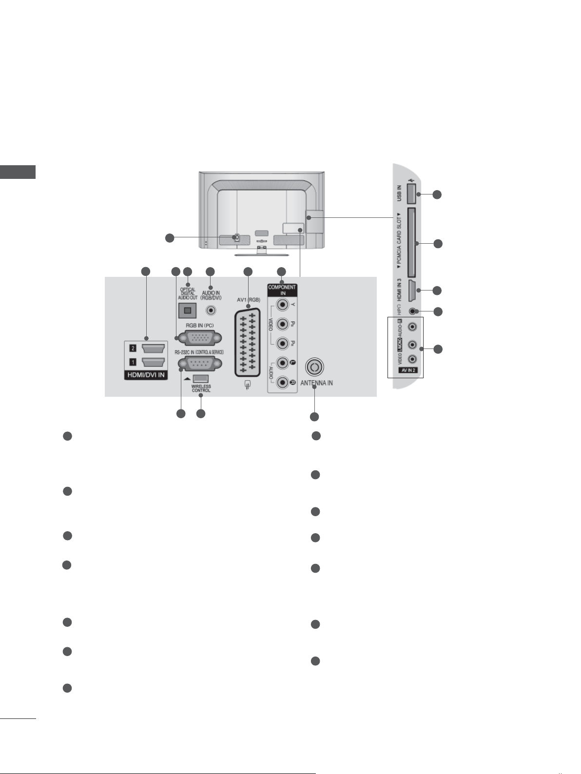
BACK PANEL INFORMATION
Only 19/22LD35**, 19/22LD34
■ Image shown may differ from your TV.
1
2
4 6 7
3
5
**
11
12
13
PREPARATION
9 10
8
1
Power Cord Socket
This TV operates on an AC power. The voltage is indicated on the Specifications page.
(
► p.137 to 147) Never attempt to operate
the TV on DC power.
2
HDMI/DVI IN Input
Connect an HDMI signal to HDMI IN. Or DVI
(VIDEO) signal to HDMI/DVI port with DVI to
HDMI cable.
3
OPTICAL DIGITAL AUDIO OUT
Connect digital audio to various types of
equipment.
Connect to a Digital Audio Component.
Use an Optical audio cable.
4
RGB/DVI Audio Input
Connect the audio from a PC or DTV.
5
Audio/Video Input
Connect audio/video output from an external
device to these jacks.
6
Euro Scart Socket (AV1)
Connect scart socket input or output from an
external device to these jacks.
7
Component Input
Connect a component video/audio device to
these jacks.
8
RGB IN Input
Connect the output from a PC.
9
RS-232C IN (CONTROL & SERVICE) PORT
Connect to the RS-232C port on a PC.
This port is used for Service or Hotel mode.
10
Antenna Input
Connect antenna or cable to this jack.
11
USB Input
Connect USB storage device to this jack.
12
PCMCIA (Personal Computer Memory
Card International Association) Card Slot
Insert the CI Module to PCMCIA CARD
SLOT.
(This feature is not available in all countries.)
13
Headphone Socket
Plug the headphone into the headphone
socket.
A-3
PREPARATION
PREPARATION
Only 26LD35**, 26LD34
**
■ Image shown may differ from your TV.
1
2
4 5 6
3
10
11
2
12
13
8 9
7
1
Power Cord Socket
This TV operates on an AC power. The voltage is indicated on the Specifications page.
(
► p.137 to 147) Never attempt to operate
the TV on DC power.
2
HDMI/DVI IN Input
Connect an HDMI signal to HDMI IN. Or DVI
(VIDEO) signal to HDMI/DVI port with DVI to
HDMI cable.
3
OPTICAL DIGITAL AUDIO OUT
Connect digital audio to various types of
equipment.
Connect to a Digital Audio Component.
Use an Optical audio cable.
4
RGB/DVI Audio Input
Connect the audio from a PC or DTV.
5
Euro Scart Socket (AV1)
Connect scart socket input or output from an
external device to these jacks.
6
Component Input
Connect a component video/audio device to
these jacks.
7
RGB IN Input
Connect the output from a PC.
8
RS-232C IN (CONTROL & SERVICE) PORT
Connect to the RS-232C port on a PC.
This port is used for Service or Hotel mode.
9
Antenna Input
Connect antenna or cable to this jack.
10
USB Input
Connect USB storage device to this jack.
PCMCIA (Personal Computer Memory
11
Card International Association) Card Slot
Insert the CI Module to PCMCIA CARD
SLOT.
(This feature is not available in all countries.)
12
Headphone Socket
Plug the headphone into the headphone
socket.
13
Audio/Video Input
Connect audio/video output from an external
device to these jacks.
A-4
Only 32LD35**, 32LD34
**
■ Image shown may differ from your TV.
1
10
PREPARATION
11
2
1
Power Cord Socket
3 4 5 6
7 98
This TV operates on an AC power. The voltage is indicated on the Specifications page.
(► p.137 to 147) Never attempt to operate
the TV on DC power.
2
HDMI/DVI IN Input
Connect an HDMI signal to HDMI IN. Or DVI
(VIDEO) signal to HDMI/DVI port with DVI to
HDMI cable.
3
OPTICAL DIGITAL AUDIO OUT
Connect digital audio to various types of
equipment.
Connect to a Digital Audio Component.
Use an Optical audio cable.
4
RGB/DVI Audio Input
Connect the audio from a PC or DTV.
5
Euro Scart Socket (AV1)
Connect scart socket input or output from an
external device to these jacks.
6
Component Input
Connect a component video/audio device to
these jacks.
2
12
13
7
RS-232C IN (CONTROL & SERVICE) PORT
Connect to the RS-232C port on a PC.
This port is used for Service or Hotel mode.
8
RGB IN Input
Connect the output from a PC.
9
Antenna Input
Connect antenna or cable to this jack.
10
USB Input
Connect USB storage device to this jack.
11
PCMCIA (Personal Computer Memory
Card International Association) Card Slot
Insert the CI Module to PCMCIA CARD
SLOT.
(This feature is not available in all countries.)
12
Headphone Socket
Plug the headphone into the headphone
socket.
13
Audio/Video Input
Connect audio/video output from an external
device to these jacks.
A-5
PREPARATION
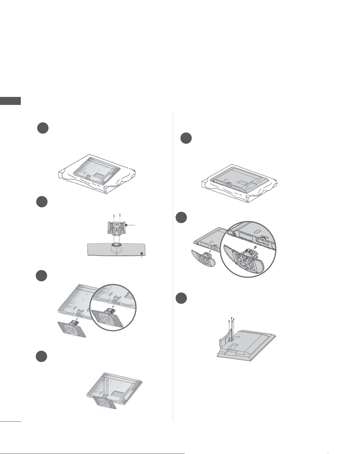
STAND INSTALLATION
■ Image shown may differ from your TV.
When assembling the desk type stand, check whether the bolt is fully tightened. (If not tightened fully,
the product can tilt forward after the product installation.) If you tighten the bolt with excessive force,
the bolt can deviate from abrasion of the tightening part of the bolt.
PREPARATION
Only 19/22LD35**, 19/22LD34
**
Only 26/32LD35**, 26/32LD34
**
Carefully place the TV screen side down
1
on a cushioned surface to protect the
screen from damage.
Assemble the TV as shown.
2
Carefully place the TV screen side down
1
on a cushioned surface to protect the
screen from damage.
Assemble the parts of the Stand Body with
2
the Stand Base of the TV.
Stand Body
Stand Base
Assemble the TV as shown.
3
A-6
Fix the 4 bolts securely using the holes in
4
the back of the TV.
NOT USING THE DESK-TYPE STAND
■ Image shown may differ from your TV.
When installing the wall-mounted unit, use the protection cover.
Only 19/22LD35**, 19/22LD34
Carefully place the TV screen side down
1
on a cushioned surface to protect the
screen from damage.
Loose the bolts from TV.
2
Detach the stand from TV.
3
**
Only 26/32LD35**, 26/32LD34
Insert the Protection Cover into the TV until
clicking sound.
Protection Cover
**
PREPARATION
Insert the Protection Cover into the TV.
4
After removing the protection paper from
the protection cover, adhere it to the TV as
shown.
Protection Cover
A-7
PREPARATION
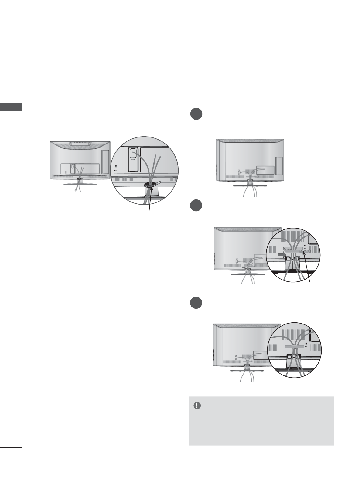
BACK COVER FOR WIRE ARRANGEMENT
■ Image shown may differ from your TV.
PREPARATION
Only 19/22LD35**, 19/22LD34
After connecting the cables as necessary, install
Cable Holder as shown and bundle the cables.
Cable Holder
**
Only 26/32LD35**, 26/32LD34
Connect the cables as necessary.
1
To connect additional equipment, see the
External Equipment Setup section.
Open the Cable Management Clip as
2
shown.
**
A-8
Cable Management Clip
Fit the Cable Management Clip as shown.
3
NOTE
►Do not use the Cable Management Clip to lift
the TV.
- If the TV is dropped, you may be injured or the
TV may be damaged.
SWIVEL STAND
(Except for 19/22LD35**, 19/22LD34**)
■ Image shown may differ from your TV.
After installing the TV, you can adjust the TV set
manually to the left or right direction by 20
degrees to suit your viewing position.
POSITIONING YOUR DISPLAY
(Only 19/22LD35**, 19/22LD34**)
■ Image shown may differ from your TV.
■ Adjust the position of the panel in various ways
for maximum comfort.
ATTACHING THE TV TO A
DESK
■ Image shown may differ from your TV.
The TV must be attached to desk so it cannot be
pulled in a forward/backward direction, potentially
causing injury or damaging the product. Use only
an attached screw.
1-Screw ( provided as parts of the product)
(Only 26/32
Stand
Desk
LD35**,
26/32
LD34**)
PREPARATION
• Tilt range
WARNING
►To prevent TV from falling over, the TV
should be securely attached to the floor/wall
per installation instructions. Tipping, shaking,
or rocking the machine may cause injury.
A-9
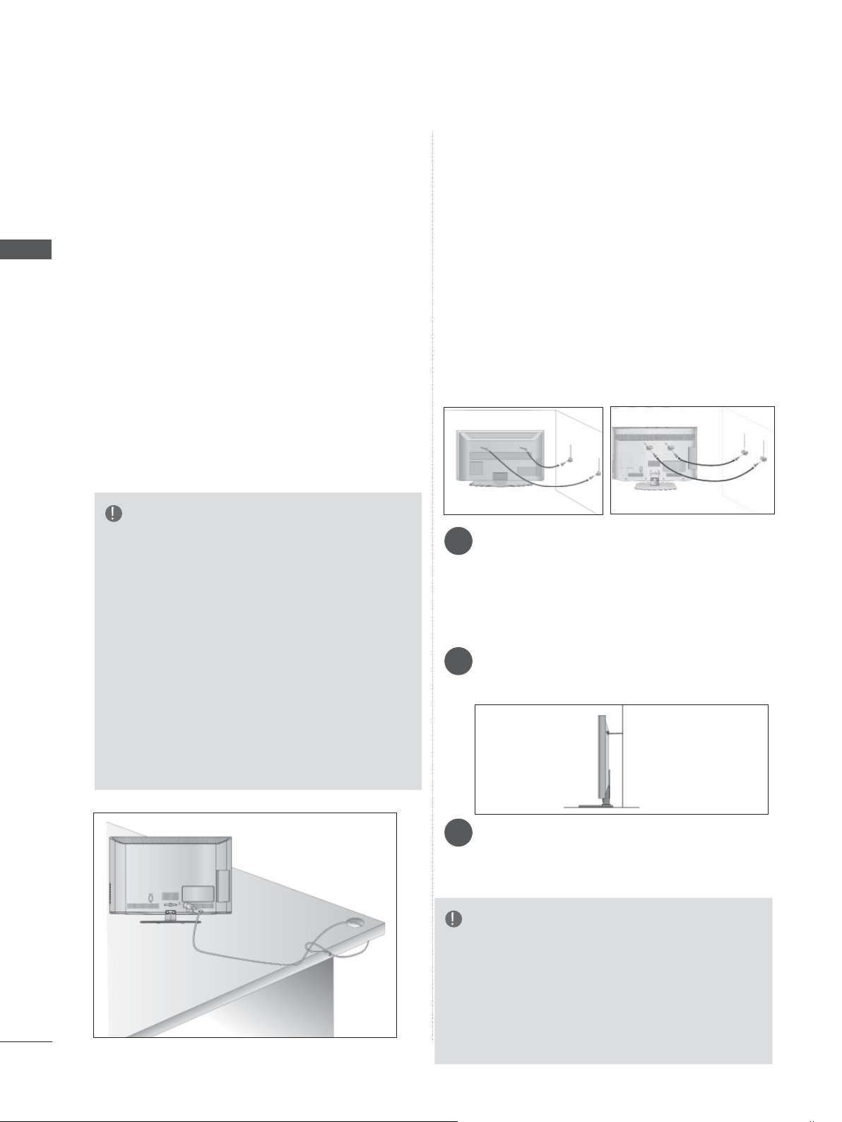
PREPARATION
PREPARATION
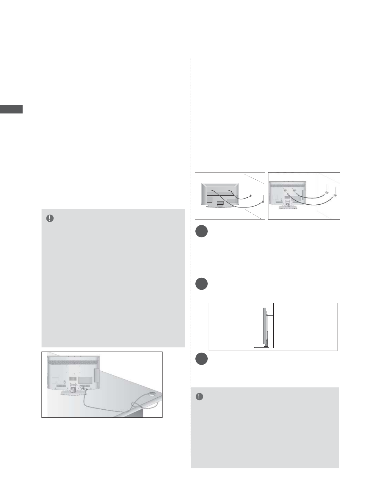
KENSINGTON SECURITY
SYSTEM
■ This feature is not available for all models.
■ Image shown may differ from your TV.
The TV is equipped with a Kensington Security
System connector on the back panel. Connect
the Kensington Security System cable as shown
below.
For the detailed installation and use of the
Kensington Security System, refer to the user’s
guide provided with the Kensington Security
System.
For further information, contact http://www.kensington.com, the internet homepage of the
Kensington
company. Kensington sells security systems for
expensive electronic equipment such as notebook PCs and LCD projectors.
NOTE
► The Kensington Security System is an optional
accessory.
► If the TV feels cold to the touch, there may be a
small “flicker” when it is turned on.
This is normal, there is nothing wrong with TV.
► Some minute dot defects may be visible on the
screen, appearing as tiny red, green, or blue
spots. However, they have no adverse effect on
the monitor's performance.
► Avoid touching the LCD screen or holding your
finger(s) against it for long periods of time.
Doing so may produce some temporary distortion effects on the screen.
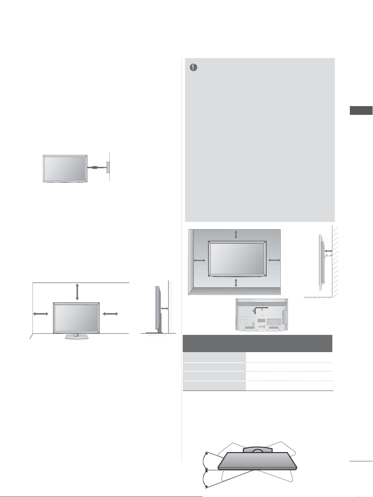
CAREFUL INSTALLATION
ADVICE
■ You should purchase necessary components
to fix the TV safety and secure to the wall on
the market.
■ Position the TV close to the wall to avoid the
possibility of it falling when pushed.
■ The instructions shown below are a safer way
to set up the TV, by fixing it to the wall, avoiding the possibility of it falling forwards if pulled.
This will prevent the TV from falling forward
and causing injury. This will also prevent the
TV from damage. Ensure that children do not
climb or hang from the TV.
1
2
Use the eye-bolts or TV brackets/bolts to fix the
1
product to the wall as shown in the picture.
(If your TV has bolts in the eyebolts, loosen
then bolts.)
* Insert the eye-bolts or TV brackets/bolts and
tighten them securely in the upper holes.
Secure the wall brackets with the bolts on the
2
wall. Match the height of the bracket that is
mounted on the wall.
1
2
2
3
A-10
Use a sturdy rope to tie the product for align-
3
ment. It is safer to tie the rope so it becomes
horizontal between the wall and the product.
NOTE
► When moving the TV undo the cords first.
► Use a platform or cabinet strong and large
enough to support the size and weight of the TV.
► To use the TV safely make sure that the height of
the bracket on the wall and on the TV is the
same.
■ The TV can be installed in various ways such as
on a wall, or on a desktop etc.
■ The TV is designed to be mounted horizontally.
EARTHING
Ensure that you connect the earth wire to prevent
possible electric shock. If grounding methods are
not possible, have a qualified electrician install a
separate circuit breaker.
Do not try to earth the TV by connecting it to telephone wires, lightening rods or gas pipes.
Power
Supply
Circuit
breaker
DESKTOP PEDESTAL
INST ALLA TION
■ Image shown may differ from your TV.
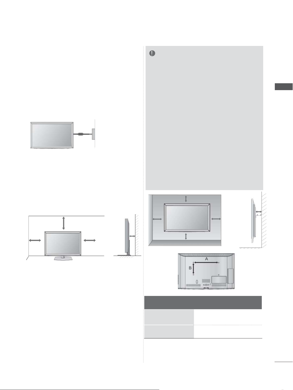
For adequate ventilation allow a clearance of 10
cm all around the TV.
NOTE
►Should Install wall mount on a solid wall per-
pendicular to the floor.
►Should use a special wall mount, if you want
to install it to ceiling or slanted wall.
►The surface that wall mount is to be mount-
ed on should be of sufficient strength to support the weight of TV set; e.g. concrete, natural rock, brick and hollow block.
►Installing screw type and length depends on
the wall mount used. Further information,
refer to the instructions included with the
mount.
►LG is not liable for any accidents or damage
to property or TV due to incorrect installation:
- Where a non-compliant VESA wall mount
is used.
- Incorrect fastening of screws to surface
which may cause TV to fall and cause personal injury.
- Not following the recommended Installation
method.
10 cm
10 cm
10 cm
PREPARATION
10 cm
10 cm
10 cm
10 cm
10 cm
WALL MOUNT: HORIZONTAL
INSTALLATION
■ We recommend the use of a LG Brand wall
mounting bracket when mounting the TV to a
wall.
■ We recommend that you purchase a wall mount-
ing bracket which supports VESA standard.
■ LG recommends that wall mounting be per-
formed by a qualified professional installer.
Model
19/22LD35
26/32LD35
19/22LD34
26/32LD34
**
**
**
**
10 cm
VESA
(A * B)
100 * 100
200 * 100
100 * 100
200 * 100
Standard
Screw
M4
M4
M4
M4
Quantity
4
4
4
4
A-11
PREPARATION
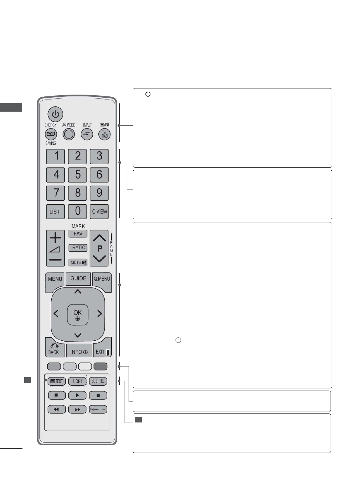
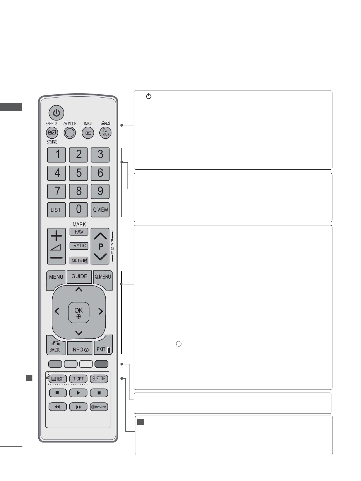
REMOTE CONTROL KEY FUNCTIONS
When using the remote control, aim it at the remote control sensor on the TV.
PREPARATION
(POWER)
ENERGY
SAVING
AV MODE
INPUT
TV/RAD
0 to 9 number
button
LIST
Q.VIEW
MENU
GUIDE
Q. MENU
Switches the TV on from standby or off to standby.
Adjust the Energy Saving mode of the TV.(
It helps you select and set images and sounds
when connecting AV devices.(
External input mode rotate in regular sequence.
p.43)
Selects Radio, TV and DTV channel.
Selects a programme.
Selects numbered items in a menu.
Displays the programme table.
Returns to the previously viewed programme.
Selects a menu.
Clears all on-screen displays and returns to TV
viewing from any menu.
Shows programme guide.(►
Select the desired quick menu source. (Aspect
Ratio, Clear Voice II , Picture Mode, Sound Mode,
Audio (or Audio Language), Sleep Timer, Skip Off/
On, USB Device).(
► p.18)
(
►
► p.50)
p.19)
p.86)
(
►
p.41)
► p.95)
(
►
A-12
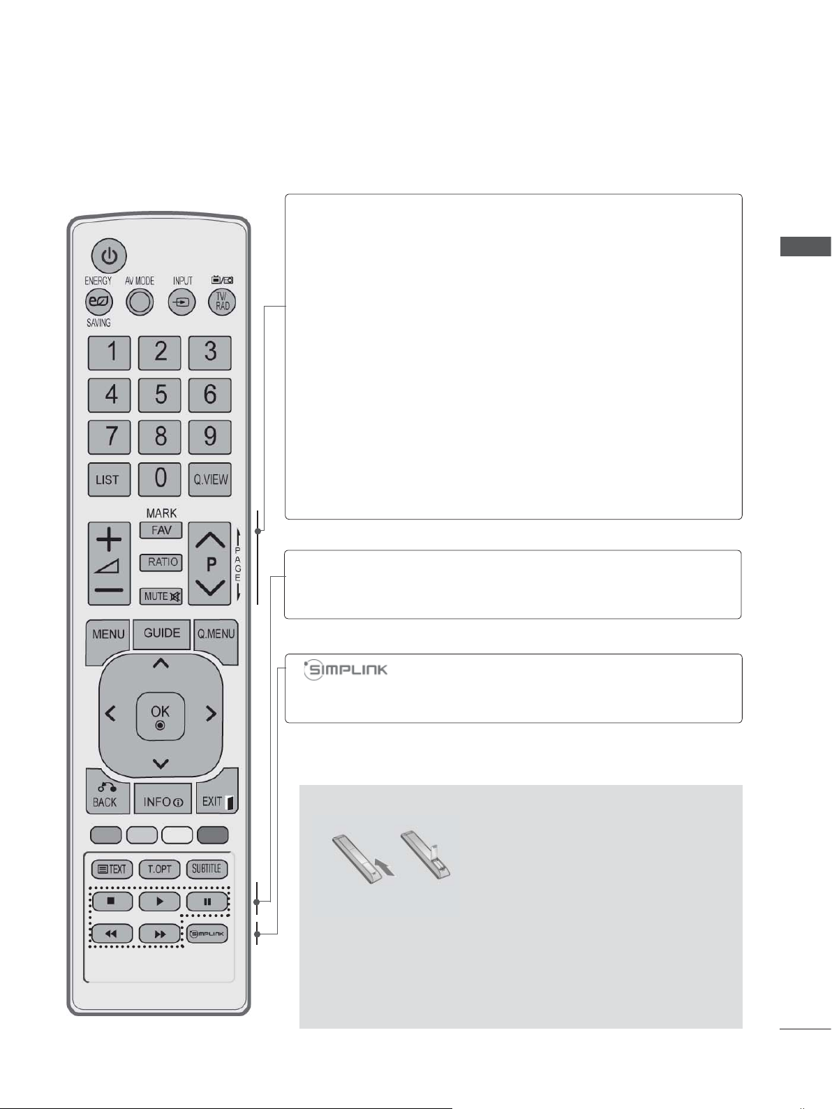
BACK
INFO i
THUMBSTICK
(Up/Down/Left/Right)
1
Coloured
buttons
1
TELETEXT
BUTTONS
SUBTITLE
Allows the user to move return one step in an interactive application, EPG or other user interaction
function.
EXIT
Clears all on-screen displays and returns to TV
viewing from any menu.
Shows the present screen information.
Allows you to navigate the on-screen menus and
adjust the system settings to your preference.
OK
Accepts your selection or displays the current
mode.
These buttons are used for teletext (on TELETEXT
models only), Programme edit.
These buttons are used for teletext.
For further details, see the ‘Teletext’ section.(
p.130)
Recalls your preferred subtitle in digital mode.
►
VOLUME UP
/DOWN
FAV
MARK
RATIO
Adjusts the volume.
Displays the selected favourite programme.
Select the input to apply the Picture Wizard
settings.
Check and un-check programmes in the USB
menu.
Selects your desired Aspect Ratio of picture.
(
► p.92)
PREPARATION
MUTE
Programme
UP/DOWN
PAGE UP/
DOWN
SIMPLINK /
MY MEDIA Menu
control buttons
Switches the sound on or off.
Selects a programme.
Move from one full set of screen information to the
next one.
Controls SIMPLINK or MY MEDIA menu(Photo List
and Music List).
See a list of AV devices connected to TV.
When you toggle this button, the Simplink menu
appears at the screen.(
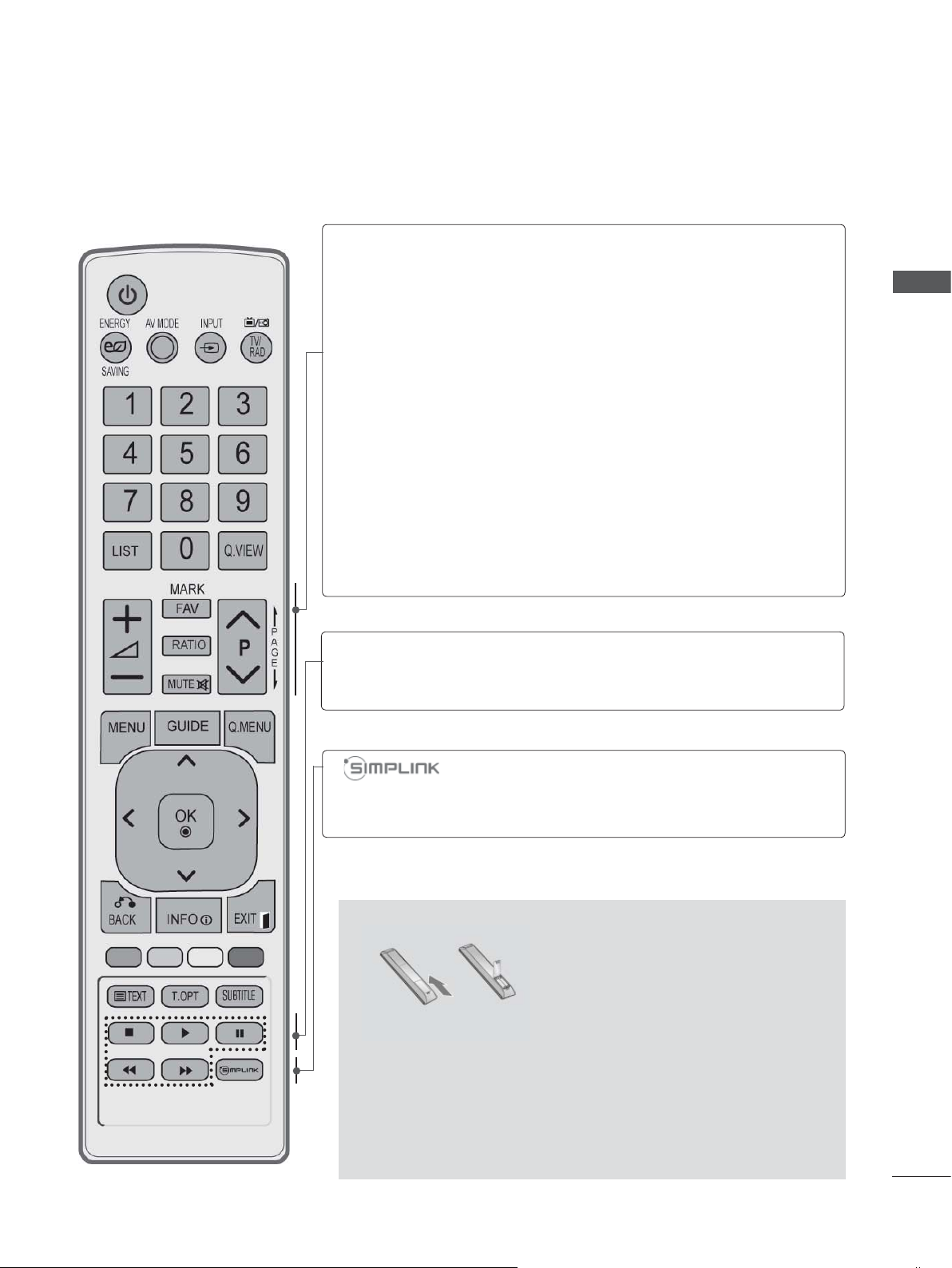
Installing Batteries
► p.46)
■ Open the battery compartment cover on the back and install
the batteries matching correct polarity (+with +,-with -).
■ Install two 1.5 V AAA batteries. Do not mix old or used batter-
ies with new ones.
■ Close cover.
■ To remove the batteries, perform the installation actions in
reverse.
A-13
PREPARATION
PREPARATION
LCD TV MODELS : 32/37/42/47LD4
26/32LD33
**
, 26/32LD32**,
***
ACCESSORIES
Ensure that the following accessories are included with your TV. If an accessory is missing, please
contact the dealer where you purchased the TV.
■ Image shown may differ from your TV.
This item is not included for all models.
* Lightly wipe any stains or
fingerprints on the surface
of the TV with the polishing cloth.
Polishing Cloth
Polishing cloth for
use on the screen.
Do not use excessive
force. This may cause
scratching or discolouration.
Owner’s Manual
Ferrite Core
(
This item is not included
for all models.
)
Batteries
(AAA)
Remote Control
Power Cord
A-14
or
x 8
(M4x20)
(Only 32/37/
42/47LD45
Bolts for stand assembly
**
(M4x24)
(Only 32/37/
42/47LD42
)
26/32LD32**,
26/32LD33**)
x 4
**
1-screw for stand fixing
,
(Only 32/37/42LD4
26/32LD32**,
26/32LD33**)
***
,
Protection
Cover
Use of ferrite core (This feature is not available for all models.)
Ferrite core can be used to reduce the electromagnetic
wave when connecting the power cord.
The closer the location of the ferrite core to the power
plug, the better it is.
Install the power plug closely.
FRONT PANEL CONTROLS
NOTE
►TV can be placed in standby mode in order to reduce the power consumption. And TV should be
switched off using the power switch on the TV if it will not be watched for some time, as this will
reduce energy consumption.
►The energy consumed during use can be significantly reduced if the level of brightness of the
picture is reduced, and this will reduce the overall running cost.
CAUTION
►Do not step on the glass stand or subject it to any impact. It may break, causing possible injury
from fragments of glass, or the TV may fall.
►Do not drag the TV. The floor or the product may be damaged.
PREPARATION
Only 32/37/42/47LD45
■ Image shown may differ from your TV.
SPEAKER
**
PROGRAMME
VOLUME
OK
MENU
INPUT
POWER
Remote Control Sensor
Power/Standby Indicator
• Illuminates red in standby mode.
• Illuminates blue when the TV is switched on.
A-15
PREPARATION
PREPARATION
Only 32/37/42/47LD42**, 26/32LD32**, 26/32LD33
Only 26LD32**, 26LD33
MENUPOWER
OKINPUT
**
VOLUME
PROGRAMME
Only 32/37/42/47LD42**,
32LD32**, 32LD33
**
**
PROGRAMME
SPEAKER
Remote Control Sensor
Power/Standby Indicator
Illuminates red in standby mode.
Illuminates blue when the TV is
switched on.
VOLUME
OK
MENU
INPUT
POWER
A-16
BACK PANEL INFORMATION
■ Image shown may differ from your TV.
1
1
2
1
Power Cord Socket
3 4 5 6
7 98
This TV operates on an AC power. The voltage is indicated on the Specifications page.
(► p.137 to 147) Never attempt to operate
the TV on DC power.
2
HDMI/DVI IN Input
Connect an HDMI signal to HDMI IN. Or DVI
(VIDEO) signal to HDMI/DVI port with DVI to
HDMI cable.
3
OPTICAL DIGITAL AUDIO OUT
Connect digital audio to various types of
equipment.
Connect to a Digital Audio Component.
Use an Optical audio cable.
4
RGB/DVI Audio Input
Connect the audio from a PC or DTV.
5
Euro Scart Socket (AV1)
Connect scart socket input or output from an
external device to these jacks.
6
Component Input
Connect a component video/audio device to
these jacks.
10
11
2
12
13
7
RS-232C IN (CONTROL & SERVICE) PORT
Connect to the RS-232C port on a PC.
This port is used for Service or Hotel mode.
8
RGB IN Input
Connect the output from a PC.
9
Antenna Input
Connect antenna or cable to this jack.
10
USB Input
Connect USB storage device to this jack.
11
PCMCIA (Personal Computer Memory
Card International Association) Card Slot
Insert the CI Module to PCMCIA CARD
SLOT.
(This feature is not available in all countries.)
12
Headphone Socket
Plug the headphone into the headphone
socket.
13
Audio/Video Input
Connect audio/video output from an external
device to these jacks.
PREPARATION
A-17
PREPARATION
STAND INSTALLATION
■ Image shown may differ from your TV
When assembling the desk type stand, check whether the bolt is fully tightened. (If not tightened fully,
the product can tilt forward after the product installation.) If you tighten the bolt with excessive force,
the bolt can deviate from abrasion of the tightening part of the bolt.
PREPARATION
Only 32/37/42/47LD45
**
Only 32/37/42/47LD42**,
Carefully place the TV screen side down
1
on a cushioned surface to protect the
screen from damage.
Assemble the parts of the Stand Body with
2
the Cover Base of the TV.
Stand Body
Cover Base
Assemble the TV as shown.
3
26/32LD32**, 26/32LD33
Carefully place the TV screen side down
1
on a cushioned surface to protect the
screen from damage.
Assemble the TV as shown.
2
**
A-18
Fix the 4 bolts securely using the holes in
4
the back of the TV.
Fix the 4 bolts securely using the holes in
3
the back of the TV.
BACK COVER FOR
ATTACHING THE TV TO A
WIRE ARRANGEMENT
■ Image shown may differ from your TV.
Connect the cables as
1
necessary.
To connect additional
equipment, see the
EXTERNAL EQUIPMENT
SETUP section.
Open the Cable Management Clip as
2
shown.
Cable Management Clip
Fit the Cable Management Clip as shown.
3
DESK
(Only 32/37/42LD4
, 26/32LD32**,
***
26/32LD33**)
■ Image shown may differ from your TV.
The TV must be attached to desk so it cannot
be pulled in a forward/backward direction,
potentially causing injury or damaging the
product. Use only an attached screw.
1-Screw
( provided as parts of the product)
Stand
PREPARATION
NOTE
►Do not use the Cable Management Clip to lift
the TV.
- If the TV is dropped, you may be injured or the
TV may be damaged.
Desk
WARNING
►To prevent TV from falling over, the TV
should be securely attached to the floor/wall
per installation instructions. Tipping, shaking,
or rocking the machine may cause injury.
NOT USING THE
DESK-TYPE STAND
■ Image shown may differ from your TV.
When installing the wall-mounted unit,
use the protection cover.
Insert the Protection
Cover into the TV until
clicking sound.
Protection Cover
A-19
PREPARATION
PREPARATION
KENSINGTON SECURITY
SYSTEM
■ This feature is not available for all models.
■ Image shown may differ from your TV.
The TV is equipped with a Kensington Security
System connector on the back panel. Connect
the Kensington Security System cable as shown
below.
For the detailed installation and use of the
Kensington Security System, refer to the user’s
guide provided with the Kensington Security
System.
For further information, contact http://www.kensington.com, the internet homepage of the
Kensington
company. Kensington sells security systems for
expensive electronic equipment such as notebook PCs and LCD projectors.
NOTE
► The Kensington Security System is an
optional accessory.
► If the TV feels cold to the touch, there may
be a small “flicker” when it is turned on.
This is normal, there is nothing wrong with
TV.
► Some minute dot defects may be visible on
the screen, appearing as tiny red, green, or
blue spots. However, they have no adverse
effect on the monitor's performance.
► Avoid touching the LCD screen or holding
your finger(s) against it for long periods of
time. Doing so may produce some temporary
distortion effects on the screen.
CAREFUL INSTALLATION
ADVICE
■ You should purchase necessary components
to fix the TV safety and secure to the wall on
the market.
■ Position the TV close to the wall to avoid the
possibility of it falling when pushed.
■ The instructions shown below are a safer way
to set up the TV, by fixing it to the wall, avoiding the possibility of it falling forwards if pulled.
This will prevent the TV from falling forward
and causing injury. This will also prevent the
TV from damage. Ensure that children do not
climb or hang from the TV.
1
2
Use the eye-bolts or TV brackets/bolts to fix the
1
product to the wall as shown in the picture.
(If your TV has bolts in the eyebolts, loosen
then bolts.)
* Insert the eye-bolts or TV brackets/bolts and
tighten them securely in the upper holes.
Secure the wall brackets with the bolts on
2
the wall. Match the height of the bracket
that is mounted on the wall.
1
10 cm
2
2
3
A-20
Use a sturdy rope to tie the product for align-
3
ment. It is safer to tie the rope so it becomes
horizontal between the wall and the product.
NOTE
►When moving the TV undo the cords first.
►Use a platform or cabinet strong and large
enough to support the size and weight of the
TV.
►To use the TV safely make sure that the
height of the bracket on the wall and on the
TV is the same.
■ The TV can be installed in various ways such as
on a wall, or on a desktop etc.
■ The TV is designed to be mounted horizontally.
EARTHING
Ensure that you connect the earth wire to
prevent possible electric shock. If grounding
methods are not possible, have a qualified
electrician install a separate circuit breaker.
Do not try to earth the TV by connecting it to
telephone wires, lightening rods or gas pipes.
Power Supply
Circuit breaker
DESKTOP PEDESTAL
NOTE
► Should Install wall mount on a solid wall per-
pendicular to the floor.
► Should use a special wall mount, if you want to
install it to ceiling or slanted wall.
► The surface that wall mount is to be mounted
on should be of sufficient strength to support
the weight of TV set; e.g. concrete, natural
rock, brick and hollow block.
► Installing screw type and length depends on
the wall mount used. Further
to the instructions included with the mount.
► LG is not liable for any accidents or damage to
property or TV due to incorrect installation:
- Where a non-compliant VESA wall mount is
used.
- Incorrect fastening of screws to surface
which may cause TV to fall and cause personal injury.
- Not following the recommended Installation
method.
information, refer
PREPARATION
INST ALLA TION
■ Image shown may differ from your TV.
For adequate ventilation allow a clearance of 10
cm all around the TV.
10 cm
10 cm
10 cm
10 cm
WALL MOUNT: HORIZONTAL
INSTALLATION
■ We recommend the use of a LG Brand wall
mounting bracket when mounting the TV to a
wall.
■ We recommend that you purchase a wall
mounting bracket which supports VESA standard.
■ LG recommends that wall mounting be per-
formed by a qualified professional installer.
10 cm
10 cm
10 cm
Model
32LD4
37/42/47LD4
26/32LD32
26/32LD33
10 cm
***
***
**
**
10 cm
VESA
(A * B)
200 * 100
200 * 200
200 * 100
200 * 100
Standard
Screw
M4
M6
M4
M4
Quantity
4
4
4
4
SWIVEL STAND
■ Image shown may differ from your TV.
After installing the TV, you can adjust the TV set
manually to the left or right direction by 20
degrees to suit your viewing position.
A-21
PREPARATION
REMOTE CONTROL KEY FUNCTIONS
When using the remote control, aim it at the remote control sensor on the TV.
PREPARATION
(POWER)
ENERGY
SAVING
AV MODE
INPUT
TV/RAD
0 to 9 number
button
LIST
Q.VIEW
MENU
GUIDE
Q. MENU
Switches the TV on from standby or off to standby.
Adjust the Energy Saving mode of the TV.(
It helps you select and set images and sounds
when connecting AV devices.(
External input mode rotate in regular sequence.
p.43)
Selects Radio, TV and DTV channel.
Selects a programme.
Selects numbered items in a menu.
Displays the programme table.
Returns to the previously viewed programme.
Selects a menu.
Clears all on-screen displays and returns to TV
viewing from any menu.
Shows programme guide.(►
Select the desired quick menu source. (Aspect
Ratio, Clear Voice II , Picture Mode, Sound Mode,
Audio (or Audio Language), Sleep Timer, Skip Off/
On, USB Device).(
► p.18)
(
►
► p.50)
p.19)
p.86)
(
►
p.41)
► p.95)
(
►
A-22
BACK
INFO i
THUMBSTICK
(Up/Down/Left/Right)
1
Coloured
buttons
1
TELETEXT
BUTTONS
SUBTITLE
Allows the user to move return one step in an interactive application, EPG or other user interaction
function.
EXIT
Clears all on-screen displays and returns to TV
viewing from any menu.
Shows the present screen information.
Allows you to navigate the on-screen menus and
adjust the system settings to your preference.
Accepts your selection or displays the current
OK
mode.
These buttons are used for teletext (on TELETEXT
models only), Programme edit.
These buttons are used for teletext.
For further details, see the ‘Teletext’ section.(
p.130)
Recalls your preferred subtitle in digital mode.
►
VOLUME UP
/DOWN
FAV
MARK
RATIO
Adjusts the volume.
Displays the selected favourite programme.
Select the input to apply the Picture Wizard
settings.
Check and un-check programmes in the USB
menu.
Selects your desired Aspect Ratio of picture.
(
► p.92)
PREPARATION
MUTE
Programme
UP/DOWN
PAGE UP/
DOWN
SIMPLINK /
MY MEDIA Menu
control buttons
Switches the sound on or off.
Selects a programme.
Move from one full set of screen information to the
next one.
Controls SIMPLINK or MY MEDIA menu(Photo List
and Music List).
See a list of AV devices connected to TV.
When you toggle this button, the Simplink menu
appears at the screen.(
Installing Batteries
► p.46)
■ Open the battery compartment cover on the back and install
the batteries matching correct polarity (+with +,-with -).
■ Install two 1.5 V AAA batteries. Do not mix old or used batter-
ies with new ones.
■ Close cover.
■ To remove the batteries, perform the installation actions in
reverse.
A-23
PREPARATION
PREPARATION
LCD TV MODELS :
32/42/46/52/60LD5
***
ACCESSORIES
Ensure that the following accessories are included with your TV. If an accessory is missing, please
contact the dealer where you purchased the TV.
■ Image shown may differ from your TV.
This item is not included for all models.
Owner’s Manual
Power Cord
Batteries
(AAA)
Ferrite Core
(
This item is not included
for all models.
Remote Control
)
Polishing Cloth
Polishing cloth for
use on the screen.
* Lightly wipe any
stains or fingerprints
on the surface of the
TV with the polishing
cloth.
Do not use excessive force. This may
cause scratching or
discolouration.
A-24
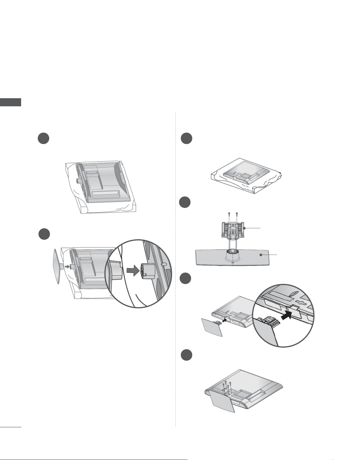
x 8
M4 x 20
Bolts for stand assembly
1-screw for stand fixing
(Only 32/42LD5
***
)
Protection
Cover
Use of ferrite core (This feature is not available for all models.)
Ferrite core can be used to reduce the electromagnetic
wave when connecting the power cord.
The closer the location of the ferrite core to the power
plug, the better it is.
Install the power plug closely.
FRONT PANEL CONTROLS
NOTE
►TV can be placed in standby mode in order to reduce the power consumption. And TV should be
switched off using the power switch on the TV if it will not be watched for some time, as this will
reduce energy consumption.
► The energy consumed during use can be significantly reduced if the level of brightness of the picture
is reduced, and this will reduce the overall running cost.
CAUTION
► Do not step on the glass stand or subject it to any impact. It may break, causing possible injury from frag-
ments of glass, or the TV may fall.
► Do not drag the TV. The floor or the product may be damaged.
■ Image shown may differ from your TV.
PROGRAMME
PREPARATION
SPEAKER
Power/Standby Indicator
• Illuminates red in standby mode.
• Illuminates blue when the TV is
switched on.
VOLUME
OK
MENU
INPUT
POWER
Remote Control Sensor
Intelligent Sensor
Adjusts picture according to
the surrounding conditions.
A-25
PREPARATION
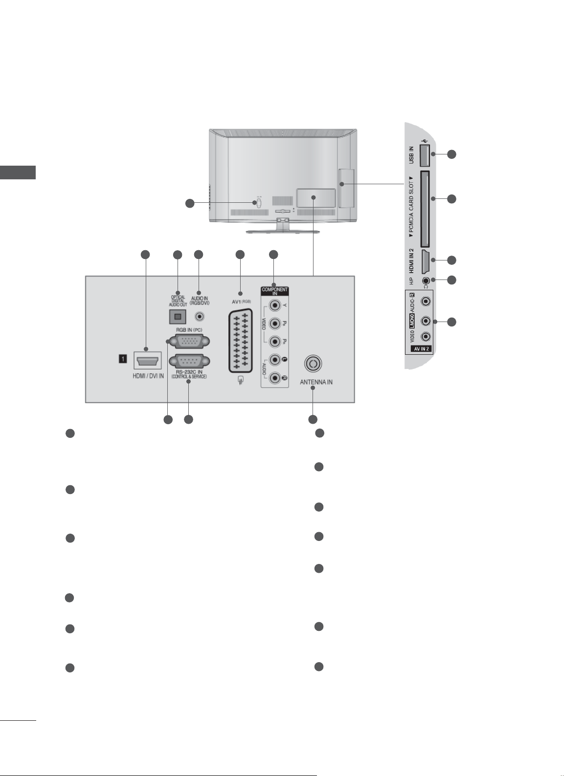
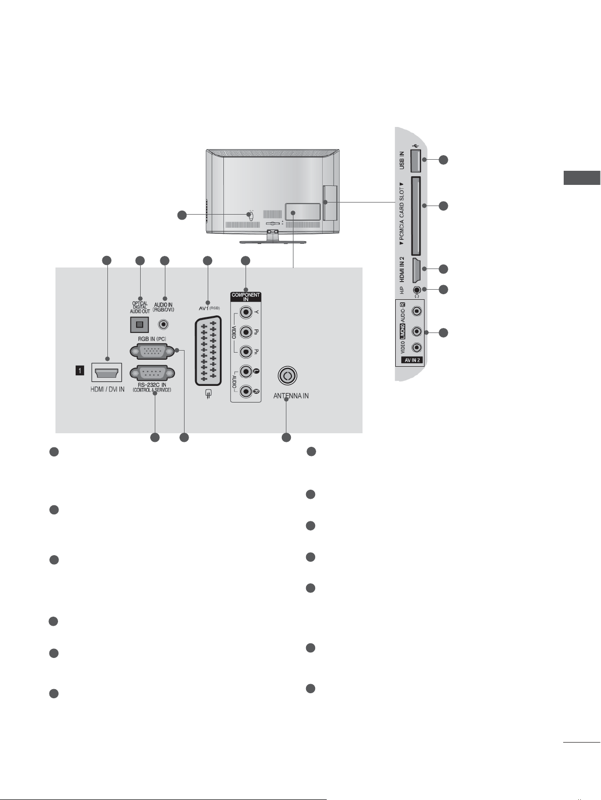
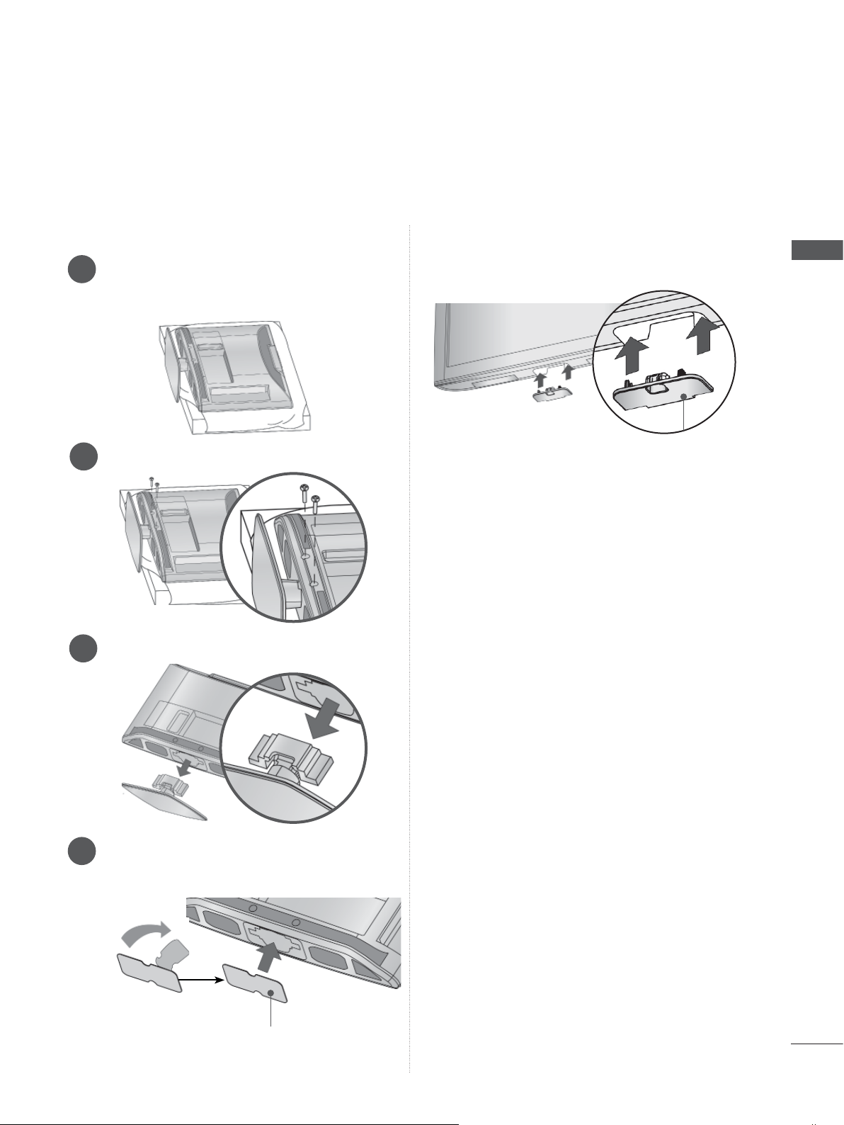
BACK PANEL INFORMATION
■ Image shown may differ from your TV.
PREPARATION
1
1
Power Cord Socket
2
3
98
64 5 7
This TV operates on an AC power. The voltage is indicated on the Specifications page.
(
► p.137 to 147) Never attempt to operate
the TV on DC power.
HDMI/DVI IN Input
2
Connect an HDMI signal to HDMI IN. Or DVI
(VIDEO) signal to HDMI/DVI port with DVI to
HDMI cable.
3
RGB IN Input
Connect the output from a PC.
OPTICAL DIGITAL AUDIO OUT
4
Connect digital audio to various types of
equipment.
Connect to a Digital Audio Component.
Use an Optical audio cable.
5
RGB/DVI Audio Input
Connect the audio from a PC or DTV.
6
Euro Scart Socket (AV1)
Connect scart socket input or output from an
external device to these jacks.
7
Component Input
Connect a component video/audio device to
these jacks.
11
12
2
13
14
10
8
RS-232C IN (CONTROL & SERVICE) PORT
Connect to the RS-232C port on a PC.
This port is used for Service or Hotel mode.
9
WIRELESS Control
Connect the Wireless Media Box to the
WIRELESS CONTROL jack on the TV.
10
Antenna Input
Connect antenna or cable to this jack.
11
USB Input
Connect USB storage device to this jack.
12
PCMCIA (Personal Computer Memory
Card International Association) Card Slot
Insert the CI Module to PCMCIA CARD
SLOT.
(This feature is not available in all countries.)
13
Headphone Socket
Plug the headphone into the headphone
socket.
14
Audio/Video Input
Connect audio/video output from an external
device to these jacks.
A-26
 Loading...