

LG 26LE5300, 42LD450, 47LD650, 32LD450, 46LD550 Owner’s Manual

OWNER’S MANUAL
LCD TV / LED LCD TV
Please read this manual carefully before operating
your set and retain it for future reference.
www.lg.com
HDMI, the HDMI logo and High-Definition Multimedia Interface are trademarks or
registered trademarks of HDMI Licensing LLC.
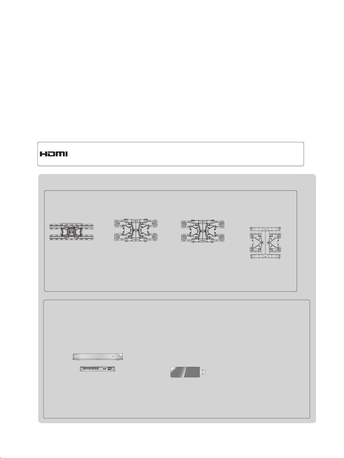
Separate purchase
Wall Mounting Bracket
LSW100B or
LSW100BG
LSW200B or
LSW200BG
LSW200BX or
LSW200BXG
LSW400B or
LSW400BG or
DSW400B or
DSW400BG
(22/26/32LD3**,
32LD4**, 32LD5**, 32LD6**,
22/26/32LE5
32LE7
***, 22/26LE6***,
***,
32LE4***, 26/32LE3***
)
(37/42/47LD4**,
42/46LD5**, 37/42/47LD6**,
37/42/47LE5
42/47LE8
37/42/47LE7
***,
***, 42/47LE4***,
42/47LX6***
(47LX9***)
*** ,
)
(52/60LD5**, 55LD6**,
55LE5
***,
55LE8
***, 55LE4***,
55LE7
***,
55LX6***, 55LX9***
Optional extras can be changed or modified for quality improvement without any notification.
Contact your dealer for buying these items.
This device only works with compatible LG LED LCD TV or LCD TV.
Wireless Media Box
(AN-WL100W)
Wireless LAN for
Broadband/
DLNA Adaptor
AV1 AV2
HDMI1 HDMI2
HDMI3
COM1 COM2 RGB WIRELESS
HDMI4
(AN-WF100)
)
WIRELESS
OUT
CONTROL
(Only 32/42/46/52/60LD5**,
32/37/42/47/55LD6**,
32/37/42/47/55LE53**,
32/37/42/47/55LE55**,
32/37/42/47/55LE7***, 42/47/55LE8***,
32/42LE45**, 42/47/55LX6***,
47/55LX9***, 32LE3***)
(Only 32/42/52LD56*,
32/37/42/47/55LD6**,
32/37/42/47/55LE55**,
32/37/42/47/55LE7***,
42/47/55LE8***, 42/47/55LX6***,
47/55LX9***)

CONTENTS
PREPARATION
Accessories .....................................................A-1
Front Panel Controls ....................................... A-4
Back Panel Information .................................A-10
Stand Installation ...........................................A-18
Woofer Installation :When Using the Wall Mount A-23
Back Cover for Wire Arrangement ................A-24
Attaching the TV to a Desk ...........................A-25
Not Using the Desk-Type Stand ................... A-26
Swivel Stand .................................................A-26
Positioning your Display ................................ A-26
Connection of TV ..........................................A-27
Kensington Security System .........................A-27
Careful Installation Advice .............................A-28
Desktop Pedestal Installation ........................ A-28
Wall Mount: Horizontal Installation ................ A-29
Remote Control Key Functions .....................A-30
EXTERNAL EQUIPMENT SETUP
Software Update ...............................................38
Picture/Sound Test ............................................42
Signal Test .........................................................43
Product/Service Information ..............................44
Network Test ......................................................45
Simple Manual ..................................................46
Selecting the Programme List ...........................47
Input List ............................................................49
Input Label ........................................................50
Data Service ......................................................51
SIMPLINK ..........................................................52
AV Mode ............................................................55
Initializing(Reset to original factory settings) ....56
NETCAST
Legal Notice ......................................................57
Netcast Menu ....................................................59
Movie Online .....................................................60
Weather info ......................................................62
Photo Album ......................................................63
CONTENTS
Antenna Connection ............................................1
Connecting with a Component Cable .................2
Connecting with an HDMI Cable.........................3
Connecting with an HDMI to DVI Cable .............4
Connecting with an RCA Cable ..........................5
Connecting with an RF Cable .............................6
Headphone Setup ...............................................6
Digital Audio Out Setup .......................................7
Connecting with a D-sub 15 Pin Cable ...............8
Usb Setup ...........................................................8
External Equipment Wireless Connection ..........9
Supported Display Resolution ...........................10
Screen Setup for PC mode ...............................12
Network Setup ...................................................16
WATCHING TV / PROGRAMME CONTROL
Turning on the TV .............................................26
Initializing Setup ...............................................26
Programme Selection ........................................26
Volume Adjustment ...........................................26
Quick Menu .......................................................27
On Screen Menus Selection and Adjustment ...28
Auto Programme Tuning ...................................30
Manual Programme Tuning ...............................31
Programme Edit ...............................................34
TO USE THE BLUETOOTH
Bluetooth? ........................................................64
Setting the Bluetooth .........................................65
Bluetooth headset ............................................66
Remove the Bluetooth device ...........................69
My Bluetooth Information ..................................70
Receiving photos from external Bluetooth device 71
Listening to the Musics from external Bluetooth
device ................................................................71
3D IMAGING
3D TECHNOLOGY ...........................................72
Viewing 3D Imaging ..........................................72
When using 3D Glasses ...................................73
3D Imaging viewing range ................................73
Watching 3D Imaging ........................................74
TO USE A USB DEVICE
When connecting a USB device .......................76
DLNA .................................................................78
Movie list ...........................................................82
Photo list ............................................................93
Music list ..........................................................100
DivX Registration Code ...................................106
Deactivation .....................................................107
I

CONTENTS
CONTENTS
GAME
Game ...............................................................108
EPG(ELECTRONIC PROGRAMME
GUIDE)(IN DIGITAL MODE)
Switch on/off EPG ...........................................110
Select a programme ........................................110
Button Function in NOW/NEXT Guide Mode .110
Button Function in 8 Day Guide Mode ........... 111
Button Function in Date Change Mode ..........111
Button Function in Extended Description Box 112
Button Function in Remind Setting Mode .......112
Button Function in Schedule List Mode ..........112
MHEG (MULTIMEDIA AND
HYPERMEDIA INFORMATION CODING
EXPERT GROUP)(IN DIGITAL MODE)
Teletext within Digital Service .........................113
Teletext in Digital Service ................................113
Switch on MHEG ............................................114
Select a Programme .......................................114
Button Function in Listing Mode .....................115
Button Function in NOW/NEXT Mode ............115
Sound Setting Adjustment -User Mode ..........136
Infinite Sound ..................................................136
Balance ...........................................................137
TV Speakers On/ Off Setup ............................138
DTV Audio Setting (in digital mode only) ........139
Selecting Digital Audio out ..............................140
Audio Reset .....................................................141
I/II
Stereo/Dual Reception (In Analogue Mode Only) 142
NICAM Reception (In Analogue Mode Only) ..143
Speaker Sound Output Selection ...................143
On-Screen Menu Language / Country Selection 144
Language Selection (In digital mode only) .....145
TIME SETTING
Clock Setup .....................................................147
Auto on/off time setting ...................................148
Sleep Timer setting .........................................149
PARENTAL CONTROL / RATINGS
Set Password & Lock System.........................150
Block Programme ............................................151
Parental Control (In Digital Mode only) ...........152
External Input Blocking ...................................153
Key Lock..........................................................154
PICTURE CONTROL
Picture Size (Aspect Ratio) Control ................116
Picture Wizard .................................................118
Energy Saving .................................................119
Preset Picture Settings ...................................120
Manual Picture Adjustment .............................121
Picture Improvement Technology ....................123
Expert Picture Control .....................................124
Picture Reset ...................................................127
Trumotion ........................................................128
LED Local Dimming ........................................129
Power Indicator ...............................................130
Mode Setting ...................................................131
Demo Mode .....................................................132
SOUND & LANGUAGE CONTROL
Auto Volume Leveler .......................................133
Clear Voice II ...................................................134
Preset Sound Settings-Sound Mode ..............135
TELETEXT
Switch on/off ...................................................155
SIMPLE Text....................................................155
TOP Text..........................................................156
FASTEXT ........................................................156
Special Teletext Functions ..............................157
APPENDIX
Troubleshooting ...............................................158
Maintenance ....................................................160
Product Specifications .....................................161
IR Codes .........................................................175
External Control Device Setup ........................176
Open Source Software Notice ........................183
II
PREPARATION
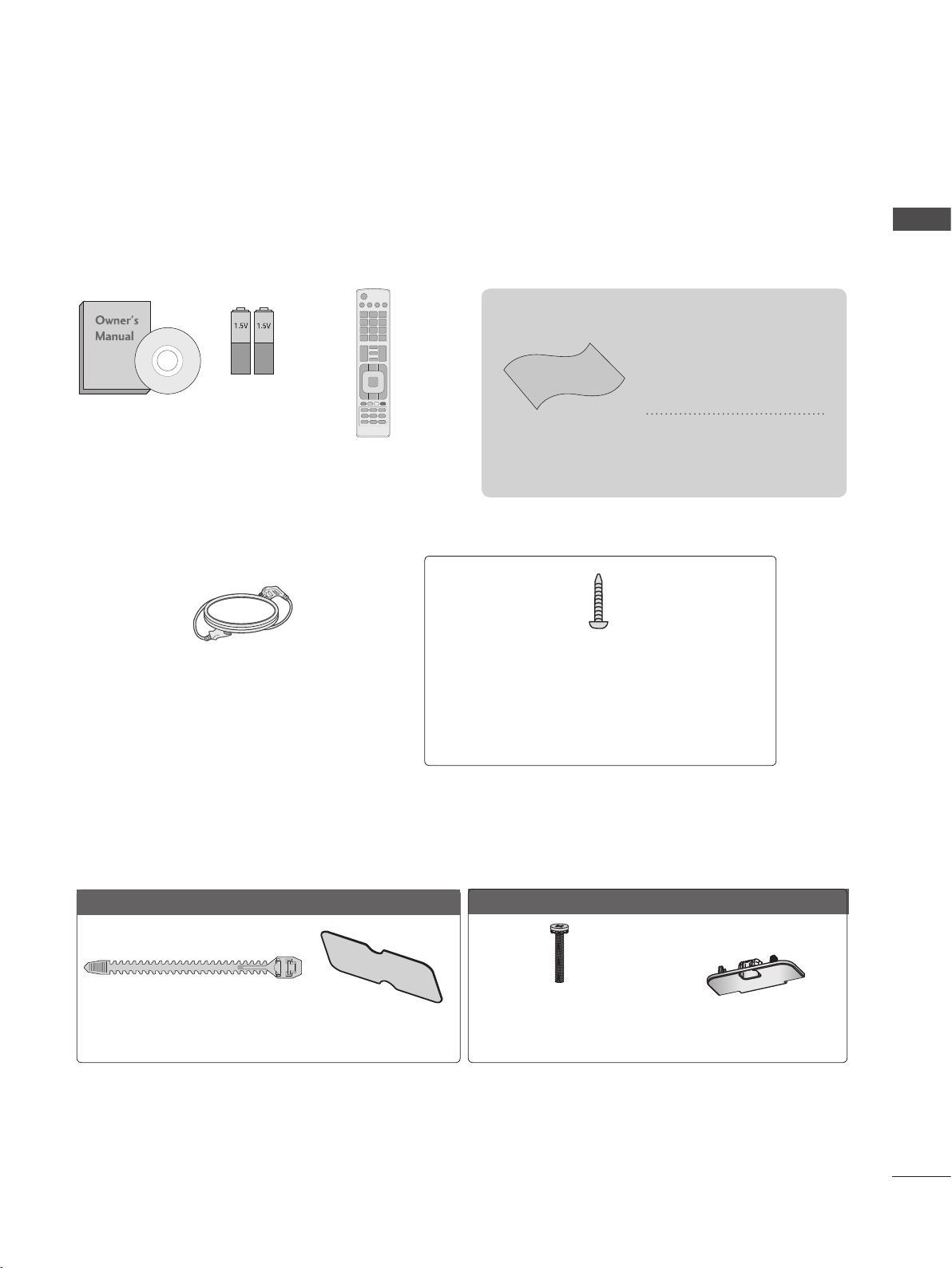
ACCESSORIES
Ensure that the following accessories are included with your TV. If an accessory is missing, please
contact the dealer where you purchased the TV.
■ Image shown may differ from your TV.
This item is not included for all models.
* Lightly wipe any stains
or fingerprints on the
surface of the TV with
the polishing cloth.
Do not use excessive
force. This may cause
scratching or discolouration.
Owner’s Manual
Batteries
(AAA)
Remote Control
Polishing Cloth
Polishing cloth for
use on the screen.
PREPARATION
Power Cord
(Except for 32/37/42/47/55LE5***,
32/37/42/47/55LE7***, 42/47/55LE8***,
42/47/55LX6***, 47/55LX9***,
32/42/47/55LE4***, 32LE3***)
Only 22LD3**
Cable Tie
(Refer to p. A-24)
Protection Cover
(Refer to p. A-26)
1-screw for stand fixing
(Refer to p. A-25)
(Only 26/32LD3**, 32/37/42LD4**,
32/42LD5**, 32/37/42LD6**, 32LE45**,
32/42/47/55LE46**, 32LE5***, 32LE7***,
32LE3***)
Only 26/32LD3**
x 8
(M4 X 20)
Bolts for stand assembly
(Refer to p. A-18)
Protection Cover
(Refer to p. A-26)
A-1
PREPARATION
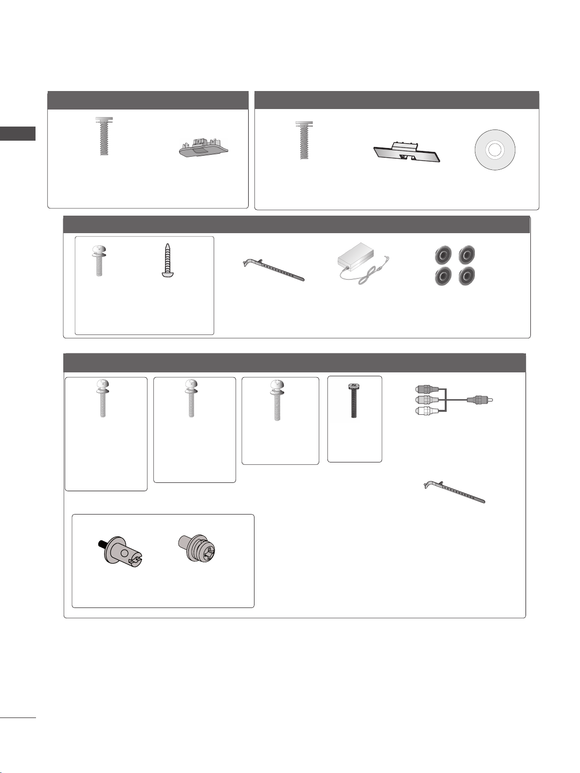
Only 32/37/42/47LD4**
PREPARATION
(M4 X 20)
Bolts for stand assembly
(Refer to p. A-18)
Only 22/26LE53**, 26LE3***
(M4x14)
Bolts for stand assembly
Only 32/37/42/47/55LE53**, 32/42/47/55LE4***, 32LE3***
x 8
Protection Cover
(Refer to p. A-26)
x 4
(M4x20)
(Only 26LE53
26LE3***
(Refer to p. A-19)
x 4
Only 32/42/46/52/60LD5**
(Only 32/42/52LD56*)
x 8
(M4 X 20)
Bolts for stand assembly
(Refer to p. A-18)
**,
)
Cable Holder
(Refer to p. A-25)
AC/DC Adaptor
(Refer to p.
Protection Cover
(Refer to p. A-26)
A-27)
Nero MediaHome
4 Essentials CD
4-Ring spacers
(Only 26LE53
26LE3***
(Refer to p. A-27)
**,
)
x 4
(M4x22)
(Only 32LE53**,
32LE45**,
32/42/47/
55LE46**,
32LE3***)
Bolts for stand assembly (Refer to p. A-19 or A-22)
(Only 32/42/47/55LE46**)
Woofer Pemnut
(Refer to p. A-23)
(M4x24)
(Only
37/42LE53**,
42LE45**)
x 2
Woofer Fixing
(Refer to p. A-23)
x 4
Screw
x 2
x 4
(M4x26)
(Only
47/55LE53**)
x 4
(M4x16)
x 2
Component gender cable,
AV gender cable
Cable Holder
(Refer to p. A-25)
A-2
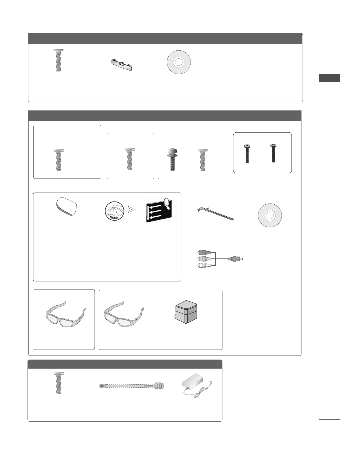
Only 32/37/42/47/55LD6**
x 8
(M4x20)
Bolts for stand assembly
(Refer to p. A-18)
Protection cover
(Refer to p. A-26)
Nero MediaHome
4 Essentials CD
Only 32/37/42/47/55LE55**, 32/37/42/47/55LE7***, 42/47/55LE8***, 42/47/55LX6***, 47/55LX9***
(Only 32/37/42/47LE55**,
32/37/42/47LE7
42/47LX6***)
x 8
***,
(Only 42/47/55LE8
x 8
***
)
(Only 55LE55**,
55LE7
***,
55LX6***)
(Only 47/55LX9***)
x 4
x 4
x 4x 4
PREPARATION
(M4 x 16)
Bolts for stand assembly
(M4 x 20)
(Refer to p. A-20)
cleansing cloths(mitt)
(Only 32/37/42/47/55LE7
***
)
Slightly wipe stained spot on the exterior only with
the cleansing cloths(mitt) for the product exterior if
there is stain or fingerprint on surface of the exterior.
For cleaning front frame, please slowly wipe in one
direction after spraying water 1~2 times on cleansing
cloths. Please remove excessive moisture after cleaning.
Excessive moisture may cause water stains on the frame.
(Only 42/47/55LX6
***
)
(Only 47/55LX9***)
x 2
3D Glasses
(AG-S100)
3D Glasses
(AG-S100)
Stand Rear Cover
(M4 x 16)(M4 x 24)
M4x12
Bolts for stand assembly
(Refer to p. A-21)
Cable Holder
(Refer to p. A-25)
Nero MediaHome
4 Essentials CD
x 2
Component gender cable,
AV gender cable
M4x22
Only 22/26LE6***
x 2
(M4x16)
Bolts for stand assembly
(Refer to p. A-21)
Cable Tie
(Refer to p. A-24)
AC/DC Adaptor
(Refer to p.
A-27)
A-3
PREPARATION
P
INPUT
MENU
OK
P
INPUT
MENU
OK
P
INPUT
MENU
OK
P
P
OK
MENU
INPUT
P
INPUT
MENU
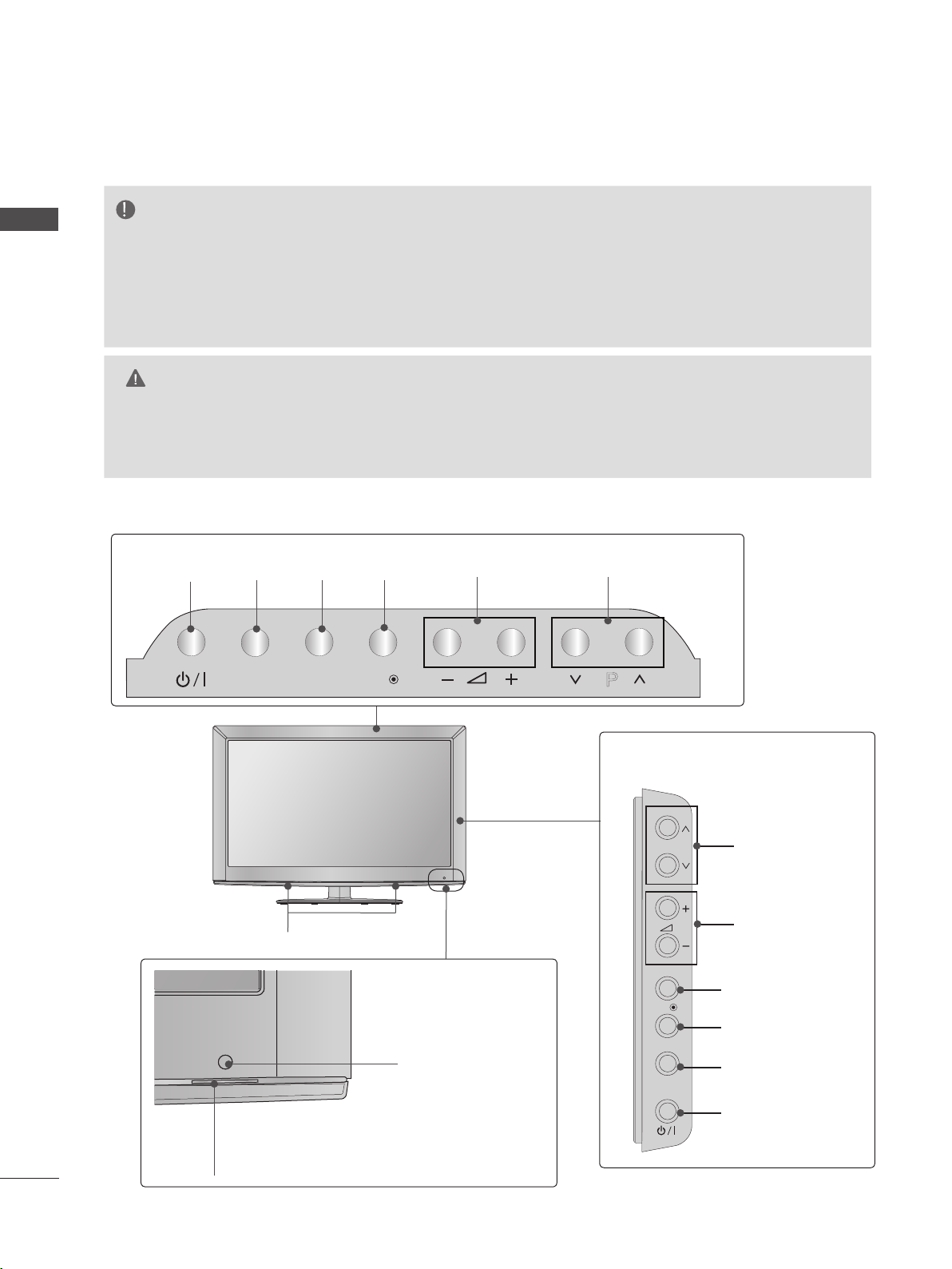
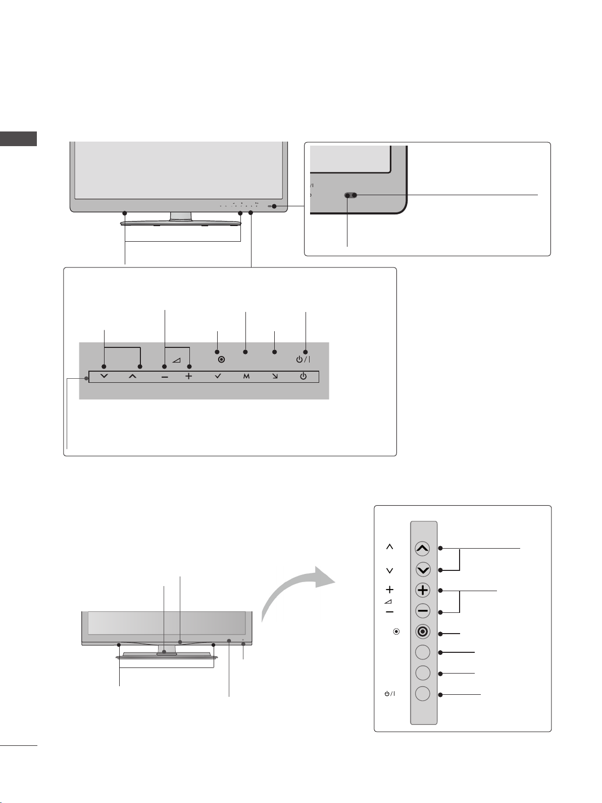
FRONT PANEL CONTROLS
NOTE
PREPARATION
►
TV can be placed in standby mode in order to reduce the power consumption. And TV should
be switched off using the power switch on the TV if it will not be watched for some time, as this
will reduce energy consumption.
► The energy consumed during use can be significantly reduced if the level of brightness of the picture
is reduced, and this will reduce the overall running cost.
CAUTION
► Do not step on the glass stand or subject it to any impact. It may break, causing possible injury from frag-
ments of glass, or the TV may fall.
► Do not drag the TV. The floor or the product may be damaged.
■ Image shown may differ from your TV.
Only 22/26/32LD3**
Only 22LD3**
INPUTPOWER
INPUT
MENU
OKMENU
OK
PROGRAMMEVOLUME
P
Only 26/32LD3**
A-4
P
PROGRAMME
SPEAKER
VOLUME
Remote Control Sensor
OK
MENU
INPUT
Power/Standby Indicator
(Can be adjusted using the Power
Indicator in the OPTION menu.)
OK
MENU
INPUT
POWER
P
OK
P
OK
P
MENU
INPUT
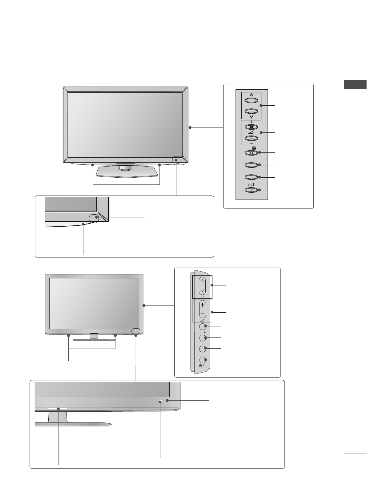
■ Image shown may differ from your TV.
OK
P
MENU
INPUT
Only 32/37/42/47LD4**
PREPARATION
SPEAKER
Power/Standby Indicator
(Can be adjusted using the Power
Indicator in the OPTION menu.)
Only 32/42/46/52/60LD5**
Remote Control Sensor
P
OK
MENU
INPUT
PROGRAMME
VOLUME
OK
MENU
INPUT
POWER
SPEAKER
Power/Standby Indicator
(Can be adjusted using the Power
Indicator in the OPTION menu.)
PROGRAMME
P
VOLUME
OK
MENU
INPUT
OK
MENU
INPUT
POWER
Remote Control Sensor
Intelligent Sensor
Adjusts picture according to
the surrounding conditions.
A-5
PREPARATION
INPUT
MENU
OK
P
INPUT
MENU
OK
P
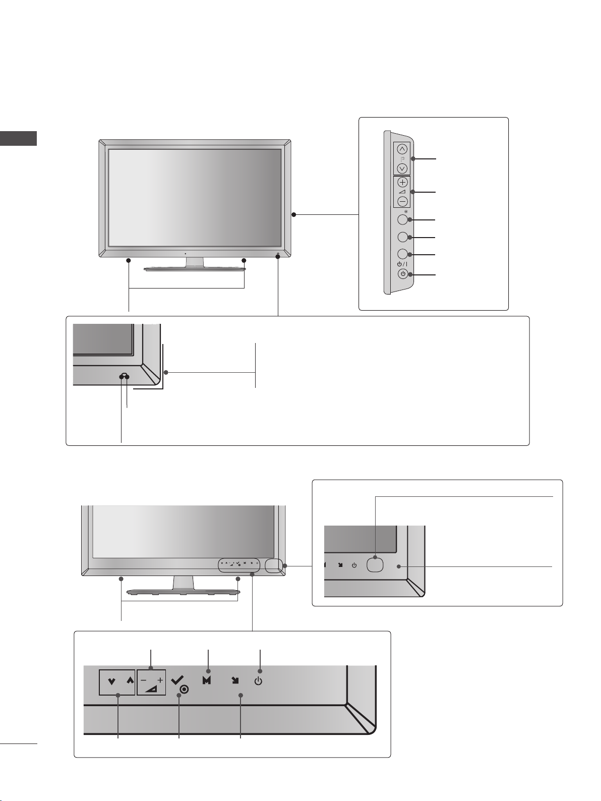
■ Image shown may differ from your TV.
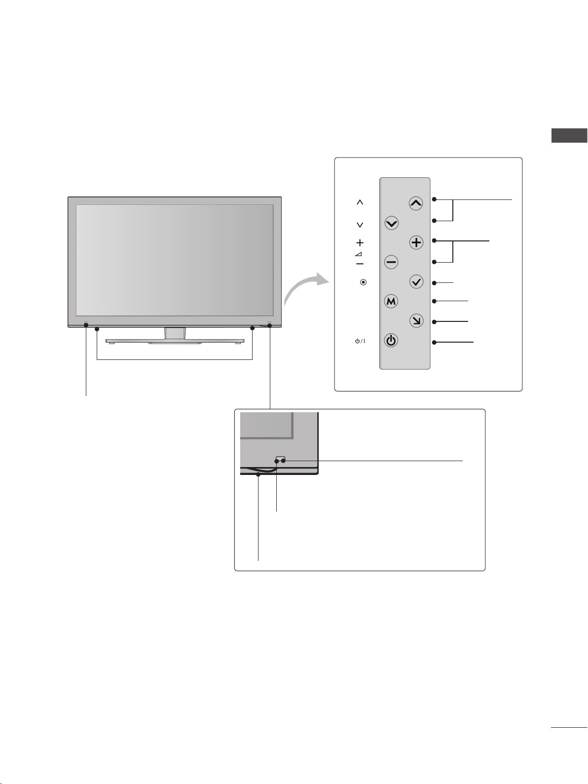
Only 32/37/42/47/55LD6**
PREPARATION
SPEAKER
Power/Standby Indicator
(Can be adjusted using the Power Indicator in the
OPTION menu.)
Remote Control Sensor
Intelligent Sensor
Adjusts picture according to the surrounding conditions.
P
OK
MENU
INPUT
PROGRAMME
VOLUME
OK
MENU
INPUT
POWER
■ Image shown may differ from your TV.
Only 22/26LE53**, 26LE3***
P
OK
SPEAKER
VOLUME MENU POWER
P
OK
MENU
INPUT
OKPROGRAMME
INPUT
Power/Standby Indicator
(Can be adjusted using the
Power Indicator in the
OPTION menu.)
MENU
INPUT
U
INPUT
Remote Control Sensor
A-6
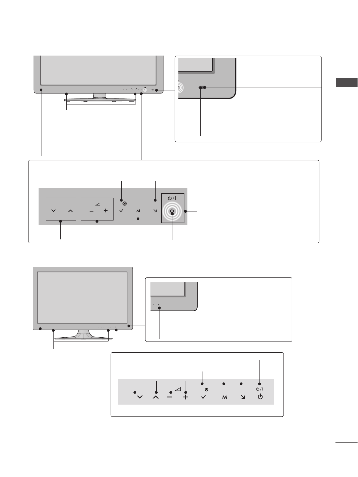
■ Image shown may differ from your TV.
Only 32/37/42/47/55LE5***, 32/37/42/47/55LE7***, 42/47/55LX6***, 32LE3***
P
MENU
OK
INPUT
SPEAKER
Intelligent Sensor
Adjusts picture according to
the surrounding conditions.
PREPARATION
Emitter (Only 42/47/55LX6
***
)
It is the part equipped with the emitter
exchanging signal with 3D glasses.
Please be careful not to block
the screen with objects or people
while watching a 3D Video.
Touch Sensor
• You can use the desired button function by touching.
INPUTOK
P
PROGRAMME
VOLUME
OK
MENU
MENU
INPUT
Only 22/26LE6***
Remote Control Sensor
Power/Standby Indicator
(Can be adjusted using the Power
Indicator in the OPTION menu.)
POWER
SPEAKER
Remote Control Sensor
Power/Standby Indicator
(Can be adjusted using the Power
Indicator in the OPTION menu.)
PROGRAMME
VOLUME
MENU
INPUTOK
OKP MENU INPUT
POWER
A-7
PREPARATION
■ Image shown may differ from your TV.
Only 42/47/55LE8***
PREPARATION
SPEAKER
Touch Sensor
• You can use the desired button function by touching.
MENU
P
OK
INPUT
Intelligent Sensor
Adjusts picture according to
the surrounding conditions.
Remote Control Sensor
PROGRAMME
P
VOLUME
OK
OK
MENU
MENU
POWER
INPUT
INPUT
Power/Standby Indicator
(Can be adjusted using the Power Indicator in the OPTION
menu.)
Only 32/42/47/55LE4***
Power/Standby Indicator
(Can be adjusted using the Power
Indicator in the OPTION menu.)
Woofer
(Only 32/42/47/55LE46**)
P
PROGRAMME
VOLUME
A-8
SPEAKER
Intelligent Sensor
Adjusts picture according to
the surrounding conditions.
Remote Control Sensor
OK
MENU
INPUT
OK
MENU
INPUT
POWER
■ Image shown may differ from your TV.
Only 47/55LX9***
PREPARATION
SPEAKER
Emitter
It is the part equipped with the
emitter exchanging signal with 3D
glasses.
Please be careful not to block
the screen with objects or
people while watching a 3D
Video.
P
OK
MENU
INPUT
Intelligent Sensor
Adjusts picture according to
the surrounding conditions.
Remote Control Sensor
PROGRAMME
VOLUME
OK
MENU
INPUT
POWER
Power/Standby Indicator
(Can be adjusted using the Power Indicator
in the OPTION menu.)
A-9
PREPARATION
K
AC-IN
H/P
SERVICE ONLY
BACK PANEL INFORMATION
■ Image shown may differ from your TV.
PREPARATION
Only 22LD3**
1
2
3 4 5 6
/DVI IN
AUDIO IN
(RGB/DVI)
OPTICAL
DIGITAL
AUDIO OUT
RS-232C IN
(CONTROL & SERVICE)
AUDIO
L(MONO)
VIDEO
10
SERVICE ONLY
11
H/P
7
AV IN
R
RGB IN
(PC)
VIDEO
COMPONENT IN
8
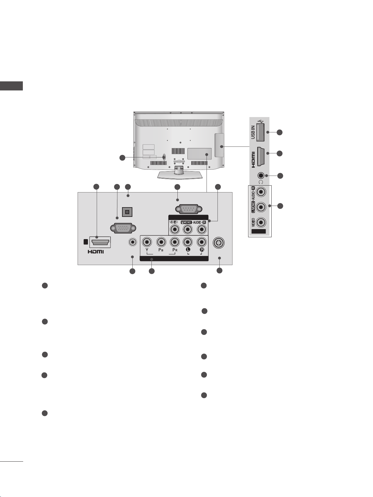
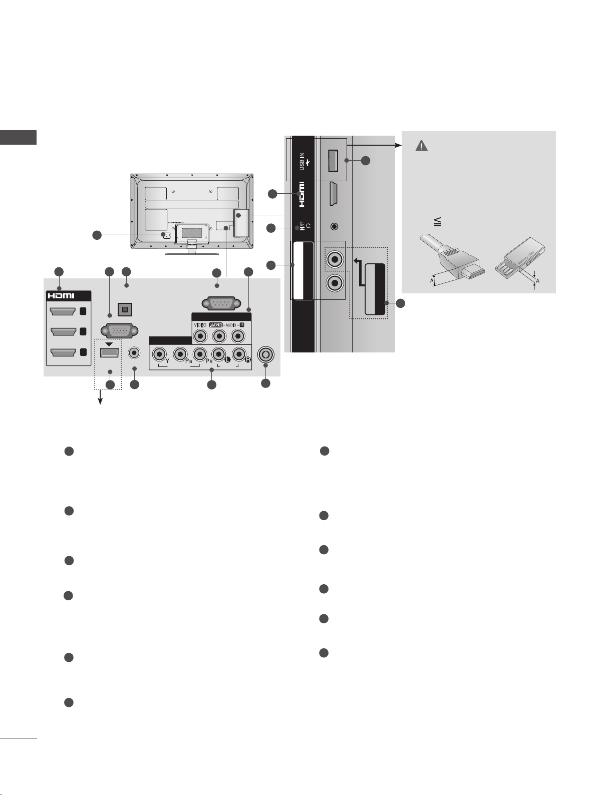
1
Power Cord Socket
This TV operates on an AC power. The voltage is indicated on the Specifications page.
(► p.161 to 173) Never attempt to operate
the TV on DC power.
2
HDMI/DVI IN Input
Connect an HDMI signal to HDMI IN. Or DVI
(VIDEO) signal to HDMI/DVI port with DVI to
HDMI cable.
3
RGB IN Input
Connect the output from a PC.
4
RGB/DVI Audio Input
Connect the audio from a PC or DTV.
5
OPTICAL DIGITAL AUDIO OUT
Connect digital audio to various types of
equipment.
Connect to a Digital Audio Component.
Use an Optical audio cable.
AUDIO
ANTENNA /
CABEL IN
9
6
RS-232C IN (CONTROL & SERVICE) PORT
Connect to the RS-232C port on a PC.
This port is used for Service or Hotel mode.
7
Audio/Video Input
Connect audio/video output from an external
device to these jacks.
8
Component Input
Connect a component video/audio device to
these jacks.
9
Antenna / Cable Input
Connect antenna or cable to this jack.
10
SERVICE ONLY PORT
11
Headphone Socket
Plug the headphone into the headphone
socket.
A-10
■ Image shown may differ from your TV.
H/P
AV IN2
IN 2
SERVICE ONLY
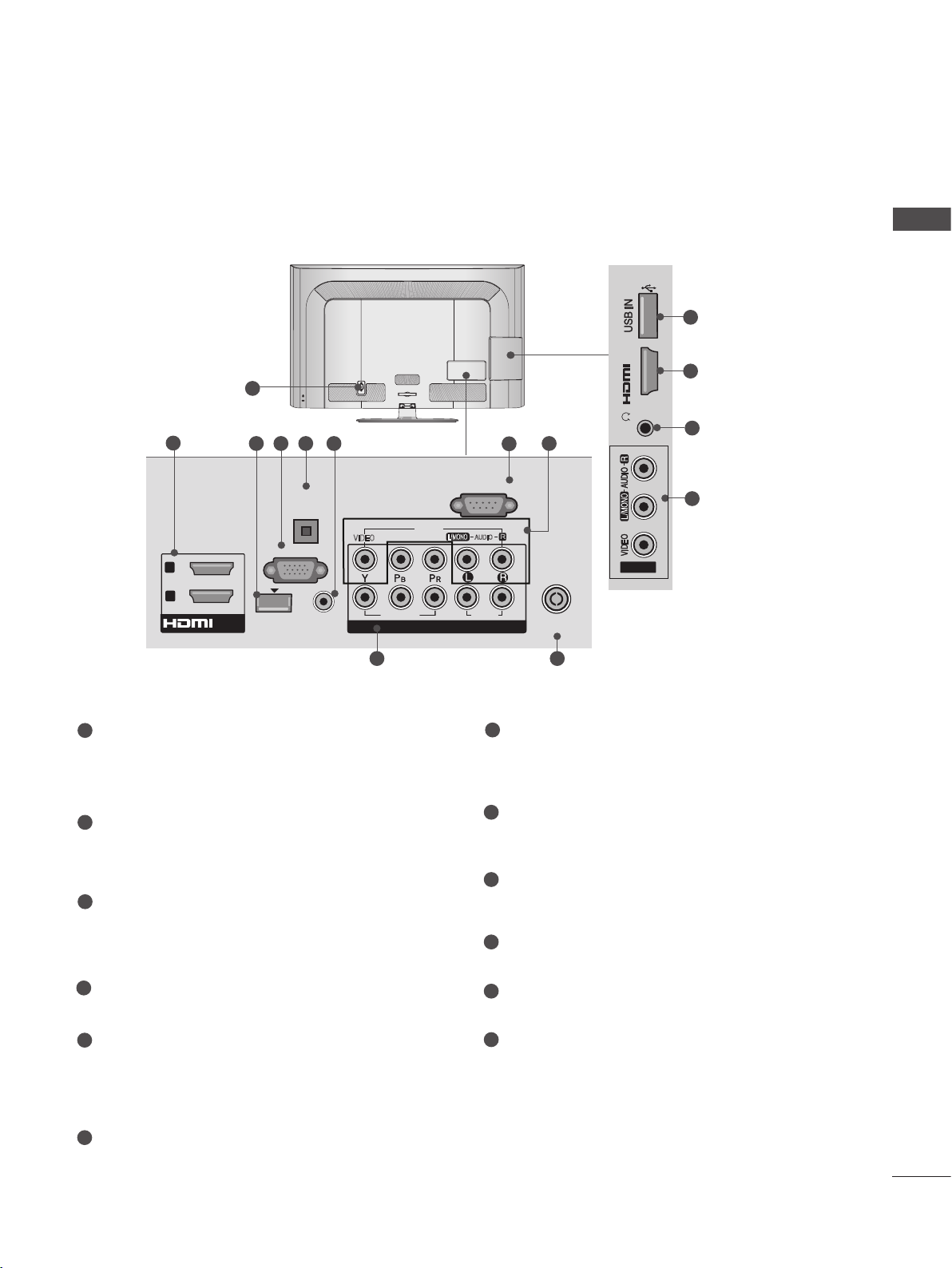
Only 26/32LD3**
1
2
3 4
OPTICAL
DIGITAL
AUDIO OUT
AC IN
CABLE MANAGEMENT
5
RS-232C IN
(CONTROL & SERVICE)
PREPARATION
10
SERVICE ONLY
IN 2
H/P
6
2
11
6
RGB IN
(PC)
1
AUDIO IN
(RGB/DVI)
7
VIDEO
COMPONENT IN
8
1
Power Cord Socket
/DVI IN
This TV operates on an AC power. The voltage is indicated on the Specifications page.
(► p.161 to 173) Never attempt to operate
the TV on DC power.
2
HDMI/DVI IN Input
Connect an HDMI signal to HDMI IN. Or DVI
(VIDEO) signal to HDMI/DVI port with DVI to
HDMI cable.
3
RGB IN Input
Connect the output from a PC.
4
OPTICAL DIGITAL AUDIO OUT
Connect digital audio to various types of
equipment.
Connect to a Digital Audio Component.
Use an Optical audio cable.
VIDEO
AV IN 1
L/MONO
AUDIO
AV IN2
ANTENNA /
CABLE IN
9
6
Audio/Video Input
Connect audio/video output from an external
device to these jacks.
7
RGB/DVI Audio Input
Connect the audio from a PC or DTV.
8
Component Input
Connect a component video/audio device to
these jacks.
9
Antenna / Cable Input
Connect antenna or cable to this jack.
10
SERVICE ONLY PORT
Headphone Socket
11
Plug the headphone into the headphone
socket.
5
RS-232C IN (CONTROL & SERVICE) PORT
Connect to the RS-232C port on a PC.
This port is used for Service or Hotel mode.
A-11
PREPARATION
R
AUDIO
HDMI IN 2 USB IN
H/P
H/P
AV IN2
IN 2
■ Image shown may differ from your TV.
PREPARATION
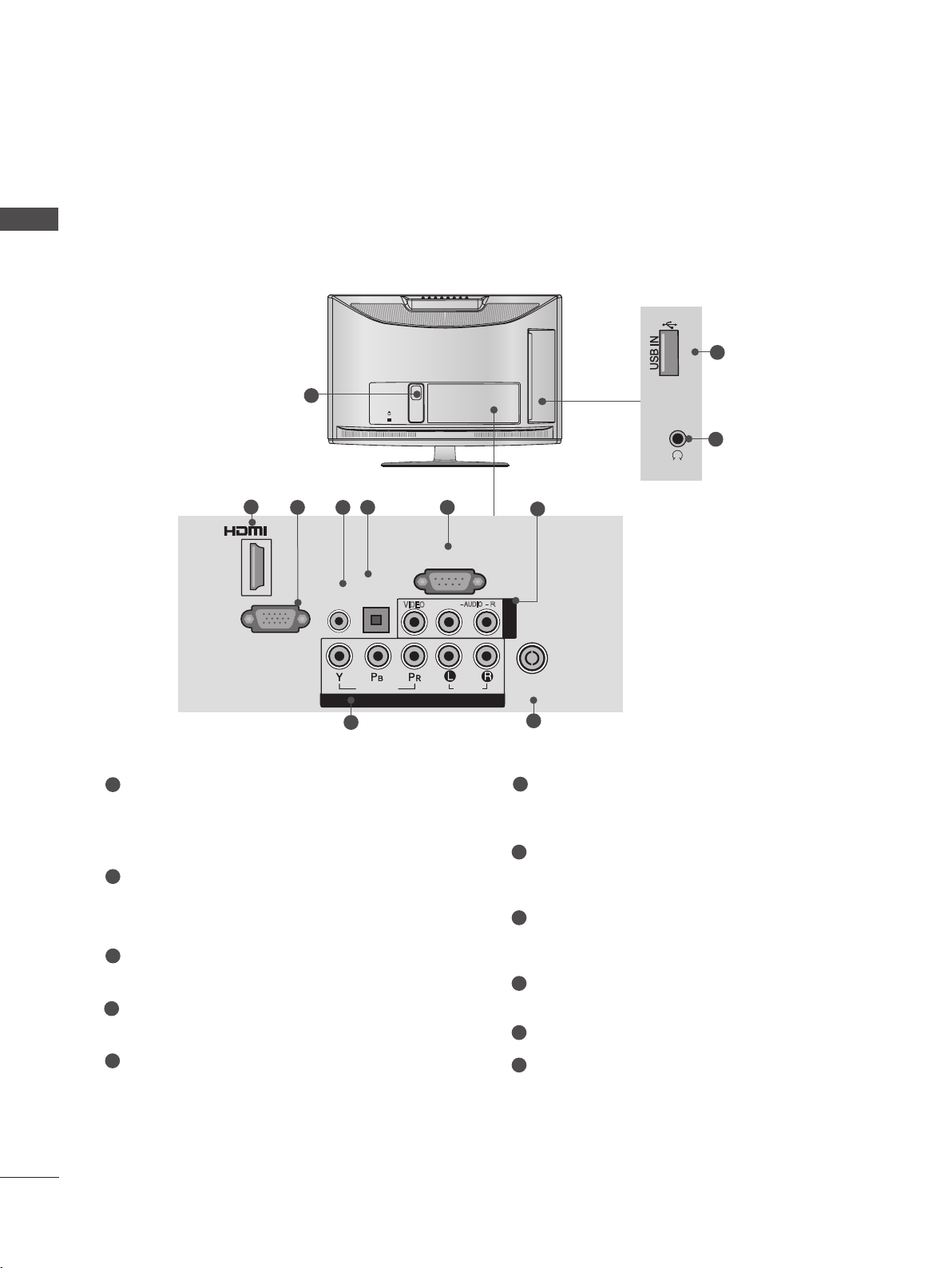
Only 32/37/42/47LD4**
10
1
2
3 4
OPTICAL
AUDIO OUT
RGB IN
DIGITAL
(PC)
1
AUDIO IN
(RGB/DVI)
7
VIDEO
COMPONENT IN
8
1
Power Cord Socket
/DVI IN
This TV operates on an AC power. The voltage is indicated on the Specifications page.
(► p.161 to 173) Never attempt to operate
the TV on DC power.
2
HDMI/DVI IN Input
Connect an HDMI signal to HDMI IN. Or DVI
(VIDEO) signal to HDMI/DVI port with DVI to
HDMI cable.
3
RGB IN Input
Connect the output from a PC.
4
OPTICAL DIGITAL AUDIO OUT
Connect digital audio to various types of
equipment.
Connect to a Digital Audio Component.
Use an Optical audio cable.
5
RS-232C IN (CONTROL & SERVICE) PORT
Connect to the RS-232C port on a PC.
This port is used for Service or Hotel mode.
5
RS-232C IN
(CONTROL & SERVICE)
AV IN 1
VIDEO
L/MONO
AUDIO
6
ANTENNA /
CABLE IN
9
6
Audio/Video Input
IN 2
H/P
AV IN2
2
11
6
Connect audio/video output from an external
device to these jacks.
7
RGB/DVI Audio Input
Connect the audio from a PC or DTV.
8
Component Input
Connect a component video/audio device to
these jacks.
9
Antenna / Cable Input
Connect antenna or cable to this jack.
10
USB Input
Connect USB storage device to this jack.
11
Headphone Socket
Plug the headphone into the headphone
socket.
A-12
■ Image shown may differ from your TV.
IN 3
H/P
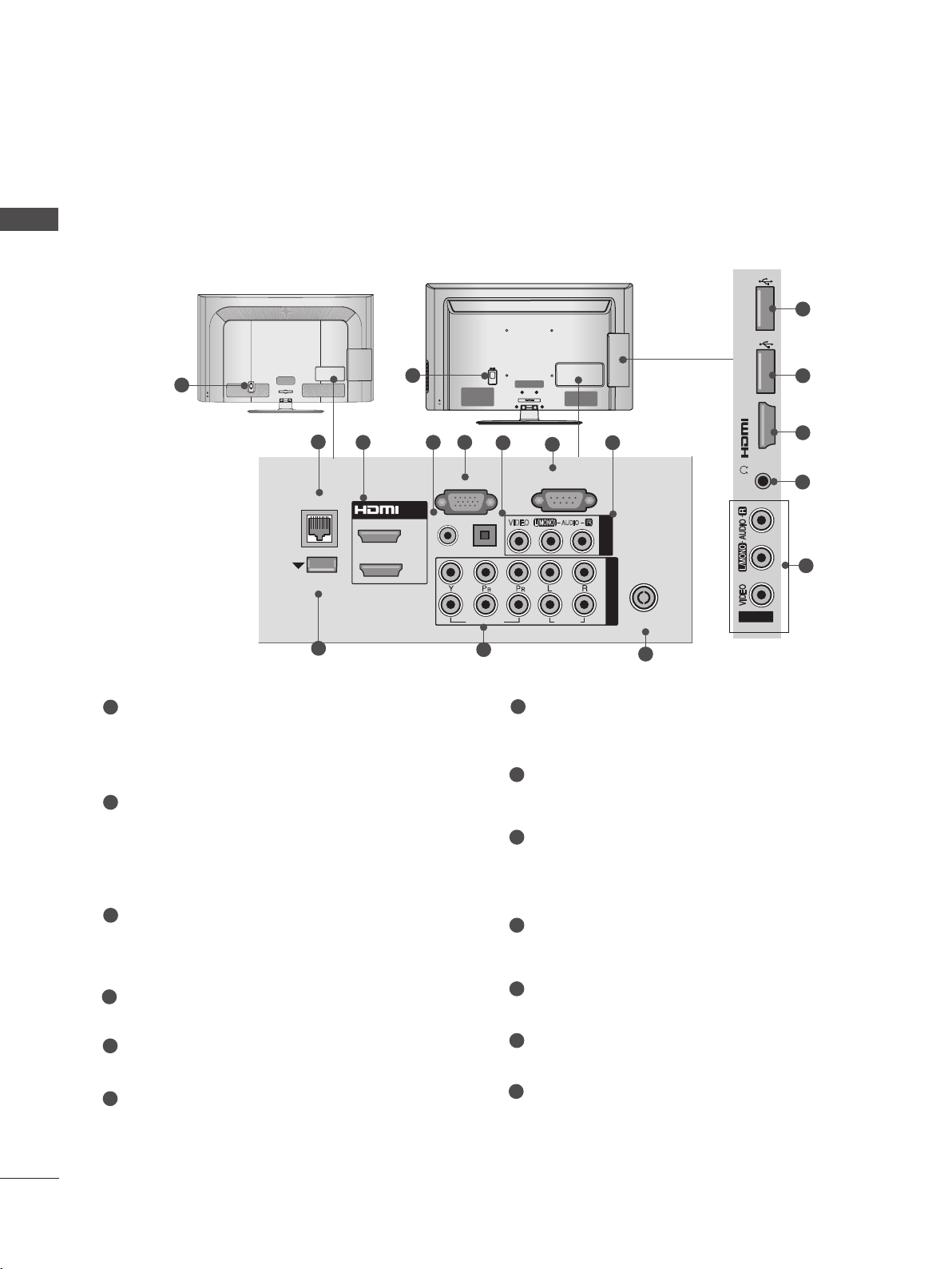
Only 32/42/46/52/60LD55*
PREPARATION
11
AC IN
VIDEO
9
2
2
1
1
Power Cord Socket
/DVI IN
1
3 4 5 6
OPTICAL
DIGITAL
AUDIO OUT
RGB IN
(PC)
WIRELESS
CONTROL
AUDIO IN
(RGB/DVI)
This TV operates on an AC power. The voltage is indicated on the Specifications page.
(► p.161 to 173) Never attempt to operate
the TV on DC power.
2
HDMI/DVI IN Input
Connect an HDMI signal to HDMI IN. Or DVI
(VIDEO) signal to HDMI/DVI port with DVI to
HDMI cable.
3
WIRELESS Control
Connect the Wireless Dongle to the TV to
control the external input devices connected
to Media Box wirelessly.
4
RGB IN Input
Connect the output from a PC.
CABLE MANAGEMENT
(CONTROL & SERVICE)
AV IN1
L/MONO
VIDEO
COMPONENT IN
COMPONENT IN
IN 3
7
8
RS-232C IN
R
AUDIO
2
1
AUDIO
7
ANTENNA /
CABLE IN
10
RS-232C IN (CONTROL & SERVICE) PORT
H/P
AV IN2
2
12
8
Connect to the RS-232C port on a PC.
This port is used for Service or Hotel mode.
8
Audio/Video Input
Connect audio/video output from an external
device to these jacks.
9
Component Input
Connect a component video/audio device to
these jacks.
10
Antenna / Cable Input
Connect antenna or cable to this jack.
11
USB Input
Connect USB storage device to this jack.
5
OPTICAL DIGITAL AUDIO OUT
Connect digital audio to various types of
equipment.
Connect to a Digital Audio Component.
Use an Optical audio cable.
6
RGB/DVI Audio Input
Connect the audio from a PC or DTV.
12
Headphone Socket
Plug the headphone into the headphone
socket.
A-13
PREPARATION
HDMI IN 3 USB IN 1
USB IN 2
h}GpuY
puGZ
H/P
USB IN 1
USB IN 2
■ Image shown may differ from your TV.
PREPARATION
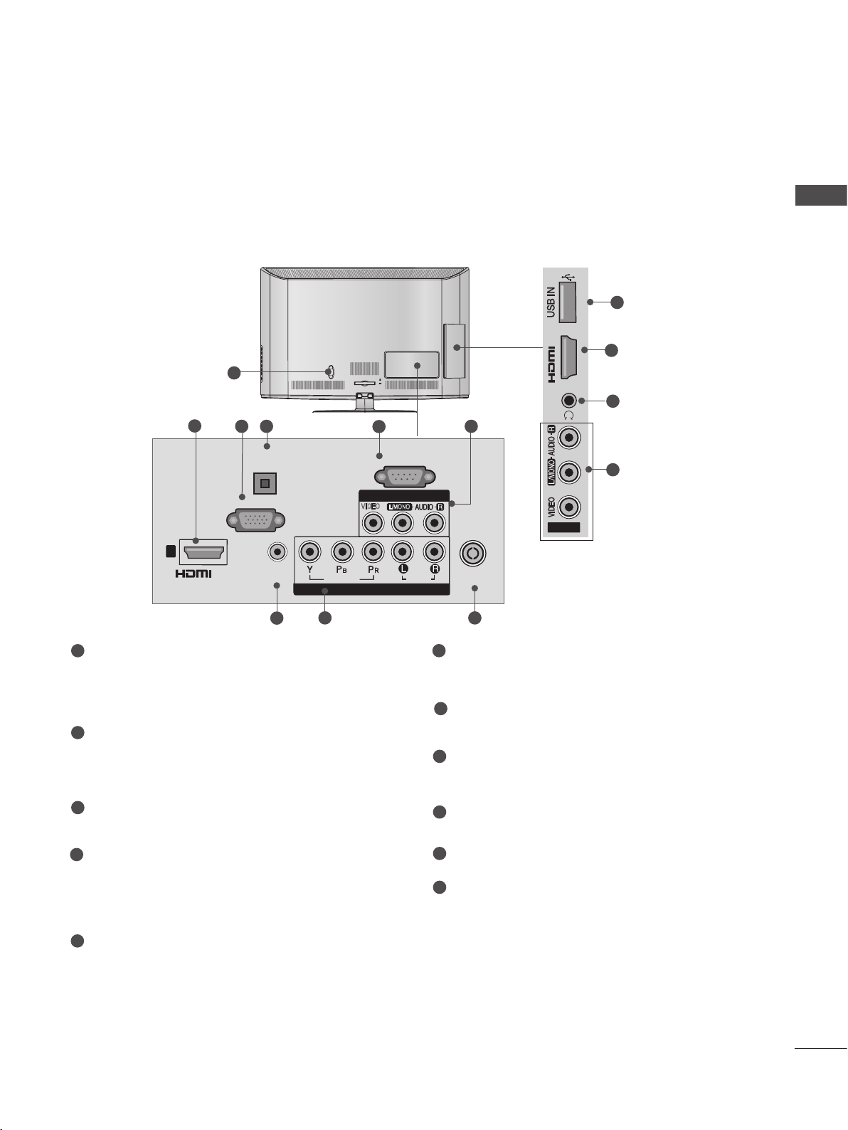
Only 32/42/52LD56*, 32/37/42/47/55LD6**
or
1
AC IN
CABLE MANAGEMENT
2
3 54
LAN
WIRELESS
CONTROL
9
1
/DVI IN
2
1
RGB IN
RGB/DVI
AUDIO IN
AC IN
(PC)
OPTICAL DIGITAL
AUDIO OUT
VIDEO
10
CABLE MANAGEMENT
6
(CONTROL & SERVICE)
L(MONO)
VIDEO
7
RS-232C IN
AUDIO
AUDIO
USB IN 2
USB IN 1
puGZ
8
H/P
AV IN 1
R
COMPONENT IN
2
1
ANTENNA /
CABLE IN
11
h}GpuY
12
12
3
13
8
1
Power Cord Socket
This TV operates on an AC power. The voltage is indicated on the Specifications page.
(► p.161 to 173) Never attempt to operate
the TV on DC power.
2
LAN
Network connection for Weather info, Photo
Album, Movie Online, etc.
Also used for video, photo and music files on
a local network.
3
HDMI/DVI IN Input
Connect an HDMI signal to HDMI IN. Or DVI
(VIDEO) signal to HDMI/DVI port with DVI to
HDMI cable.
4
RGB/DVI Audio Input
Connect the audio from a PC or DTV.
5
RGB IN Input
Connect the output from a PC.
6
OPTICAL DIGITAL AUDIO OUT
Connect digital audio to various types of
equipment.
Connect to a Digital Audio Component.
Use an Optical audio cable.
7
RS-232C IN (CONTROL & SERVICE) PORT
Connect to the RS-232C port on a PC.
This port is used for Service or Hotel mode.
8
Audio/Video Input
Connect audio/video output from an external
device to these jacks.
9
WIRELESS Control
Connect the Wireless Dongle to the TV to
control the external input devices connected
to Media Box wirelessly.
10
Component Input
Connect a component video/audio device to
these jacks.
11
Antenna / Cable Input
Connect antenna or cable to this jack.
12
USB Input
Connect USB storage device to this jack.
13
Headphone Socket
Plug the headphone into the headphone
socket.
A-14
H/P
IN 3
H/P
H/P
IN 3
■ Image shown may differ from your TV.
Only 22/26LE53**, 22/26LE6***, 26LE3***
1
2
2
/DVI IN
1
(DVI)
RGB IN
7
(PC)
DC-IN
1
DC ADAPTER PORT
Connect to the power cord socket.
3
AUDIO IN
(RGB/DVI)
4
OPTICAL
DIGITAL
AUDIO OUT
VIDEO
COMPONENT IN
8
5
RS-232C IN
(CONTROL & SERVICE)
AV IN
VIDEO
L(MONO)
AUDIO
6
Only 22LE53**
ANTENNA /
CABLE IN
9
10
2
H/P
11
IN 3
H/P
Only 26LE53**,
26LE3***
7
RGB IN Input
Connect the output from a PC.
10
IN 3
2
11
H/P
Only 22/26LE6***
PREPARATION
2
HDMI/DVI IN Input
Connect an HDMI signal to HDMI IN. Or DVI
(VIDEO) signal to HDMI/DVI port with DVI to
HDMI cable.
3
RGB/DVI Audio Input
Connect the audio from a PC or DTV.
4
OPTICAL DIGITAL AUDIO OUT
Connect digital audio to various types of
equipment.
Connect to a Digital Audio Component.
Use an Optical audio cable.
5
RS-232C IN (CONTROL & SERVICE) PORT
Connect to the RS-232C port on a PC.
This port is used for Service or Hotel mode.
6
Audio/Video Input
Connect audio/video output from an external
device to these jacks.
8
Component Input
Connect a component video/audio device to
these jacks.
9
Antenna / Cable Input
Connect antenna or cable to this jack.
10
USB Input
Connect USB storage device to this jack.
11
Headphone Socket
Plug the headphone into the headphone
socket.
A-15
PREPARATION
H/P
USB IN
/ AUDIO
IN 4
Y P
B
P
R
USB IN 2
USB IN 1
■ Image shown may differ from your TV.
PREPARATION
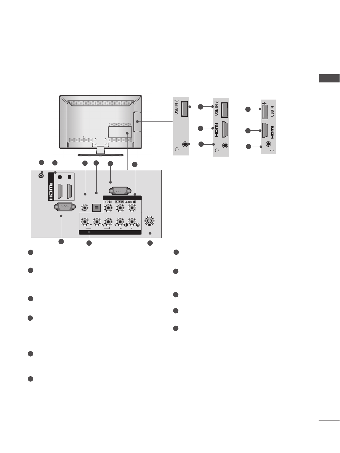
Only 32/37/42/47/55LE53**, 32/42/47/55LE4***,
32LE3***
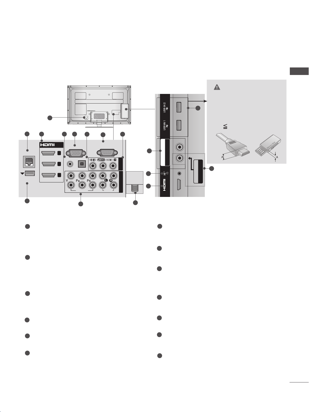
1
CAUTION
USB IN
11
► Use a product with the follow-
ing thickness for optimal con-
2
IN 4
nection to HDMI cable(only
HDMI IN 4) / USB device.
12
H/P
*A 10 mm
2 43
OPTICAL
/DVI IN
3
2
1
(DVI)
1
Power Cord Socket
DIGITAL
AUDIO OUT
RGB IN
WIRELESS
CONTROL
7 9
Except 32/42/47/55LE46**
(PC)
AUDIO IN
(RGB/DVI)
8
COMPONENT IN1
VIDEO
5
RS-232C IN
(CONTROL & SERVICE)
AV IN 1
L(MONO)
VIDEO
AUDIO
AUDIO
This TV operates on an AC power. The voltage is indicated on the Specifications page.
(► p.161 to 173) Never attempt to operate
the TV on DC power.
HDMI/DVI IN Input
2
Connect an HDMI signal to HDMI IN. Or DVI
(VIDEO) signal to HDMI/DVI port with DVI to
HDMI cable.
3
RGB IN Input
Connect the output from a PC.
OPTICAL DIGITAL AUDIO OUT
4
Connect digital audio to various types of
equipment.
Connect to a Digital Audio Component.
Use an Optical audio cable.
5
RS-232C IN (CONTROL & SERVICE) PORT
Connect to the RS-232C port on a PC.
This port is used for Service or Hotel mode.
6
Audio/Video Input
Connect audio/video output from an external
device to these jacks.
R
6
9
ANTENNA /
CABLE IN
10
/ AUDIO
R
P
B
Y P
COMPONENT IN2
7
WIRELESS Control
AV IN2
6
VIDEO / AUDIO
(Except 32/42/47/55LE46**)
Connect the Wireless Dongle to the TV to
control the external input devices connected
to Media Box wirelessly.
8
RGB/DVI Audio Input
Connect the audio from a PC or DTV.
Component Input
9
Connect a component video/audio device to
these jacks.
10
Antenna / Cable Input
Connect antenna or cable to this jack.
11
USB Input
Connect USB storage device to this jack.
Headphone Socket
12
Plug the headphone into the headphone
socket.
A-16
USB IN 2
USB IN 1
■ Image shown may differ from your TV.
USB IN 2
USB IN 1
COMPONENT IN3
AUDIO / Y P
B
P
R
Only 32/37/42/47/55LE55**, 32/37/42/47/55LE7***, 42/47/55LE8***,
42/47/55LX6***, 47/55LX9***
USB IN 2
1
2
LAN
WIRELESS
CONTROL
9
3 54
/DVI IN
3
2
1
RGB IN
(RGB/DVI)
AUDIO IN
2
1
(PC)
OPTICAL DIGITAL
AUDIO OUT
VIDEO
10
6
(CONTROL & SERVICE)
L(MONO)
VIDEO
7
RS-232C IN
AUDIO
AUDIO
R
8
AV IN 1
COMPONENT IN
ANTENNA/
CABLE IN
13
10
12
3
USB IN 1
B PR
COMPONENT IN3
AUDIO / Y P
H/P
IN 4
11
*A 10 mm
8
AV IN2
VIDEO / AUDIO
PREPARATION
CAUTION
► Use a product with the follow-
ing thickness for optimal connection to HDMI cable(only
HDMI IN 4) / USB device.
1
Power Cord Socket
This TV operates on an AC power. The voltage is indicated on the Specifications page.
(► p.161 to 173) Never attempt to operate
the TV on DC power.
2
LAN
Network connection for Weather info, Photo
Album, Movie Online, etc.
Also used for video, photo and music files on
a local network.
3
HDMI/DVI IN Input
Connect an HDMI signal to HDMI IN. Or DVI
(VIDEO) signal to HDMI/DVI port with DVI to
HDMI cable.
4
RGB/DVI Audio Input
Connect the audio from a PC or DTV.
5
RGB IN Input
Connect the output from a PC.
6
OPTICAL DIGITAL AUDIO OUT
Connect digital audio to various types of
equipment.
Connect to a Digital Audio Component.
Use an Optical audio cable.
7
RS-232C IN (CONTROL & SERVICE) PORT
Connect to the RS-232C port on a PC.
This port is used for Service or Hotel mode.
8
Audio/Video Input
Connect audio/video output from an external
device to these jacks.
9
WIRELESS Control
Connect the Wireless Dongle to the TV to
control the external input devices connected
to Media Box wirelessly.
10
Component Input
Connect a component video/audio device to
these jacks.
11
USB Input
Connect USB storage device to this jack.
12
Headphone Socket
Plug the headphone into the headphone
socket.
13
Antenna / Cable Input
Connect antenna or cable to this jack.
A-17
PREPARATION
M4X20
M4X20
M4X20
M4X20
M4X20
STAND INSTALLATION
■ Image shown may differ from your TV.
PREPARATION
When assembling the desk type stand, check whether the bolt is fully tightened. (If not tightened fully,
the product can tilt forward after the product installation.) If you tighten the bolt with excessive force,
the bolt can deviate from abrasion of the tightening part of the bolt.
Only 22LD3**
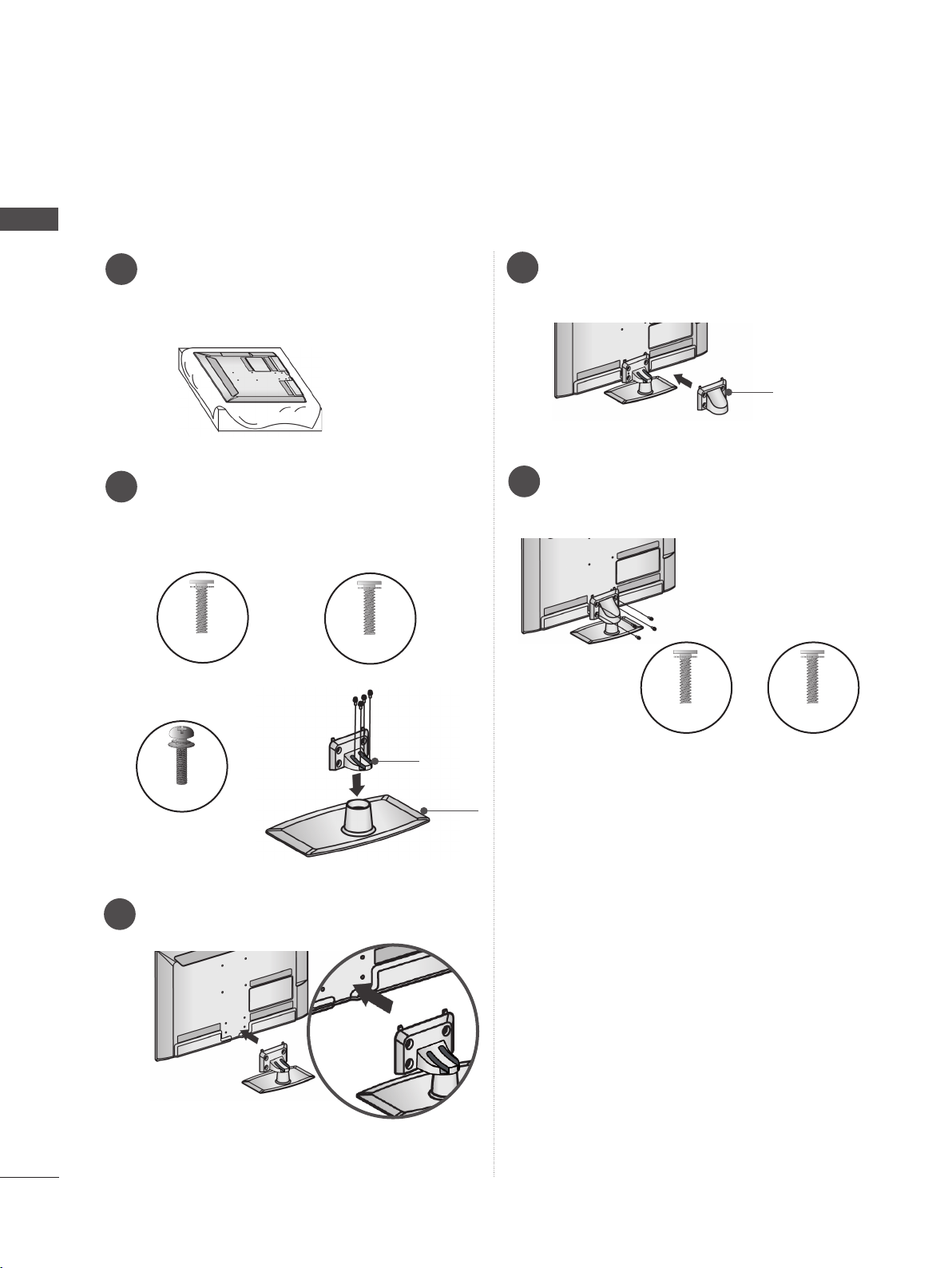
Carefully place the TV screen side down
1
on a cushioned surface to protect the
screen from damage.
Only 26/32LD3**, 32/37/42/47LD4**,
32/42/46/52/60LD5**, 32/37/42/47/55LD6**
Carefully place the TV screen side down
1
on a cushioned surface to protect the
screen from damage.
Assemble the TV as shown.
2
Assemble the parts of the Stand Body with
2
the Stand Base of the TV.
Stand Body
Stand Base
Assemble the TV as shown.
3
Fix the 4 bolts securely using the holes in
4
the back of the TV.
A-18
■ Image shown may differ from your TV.
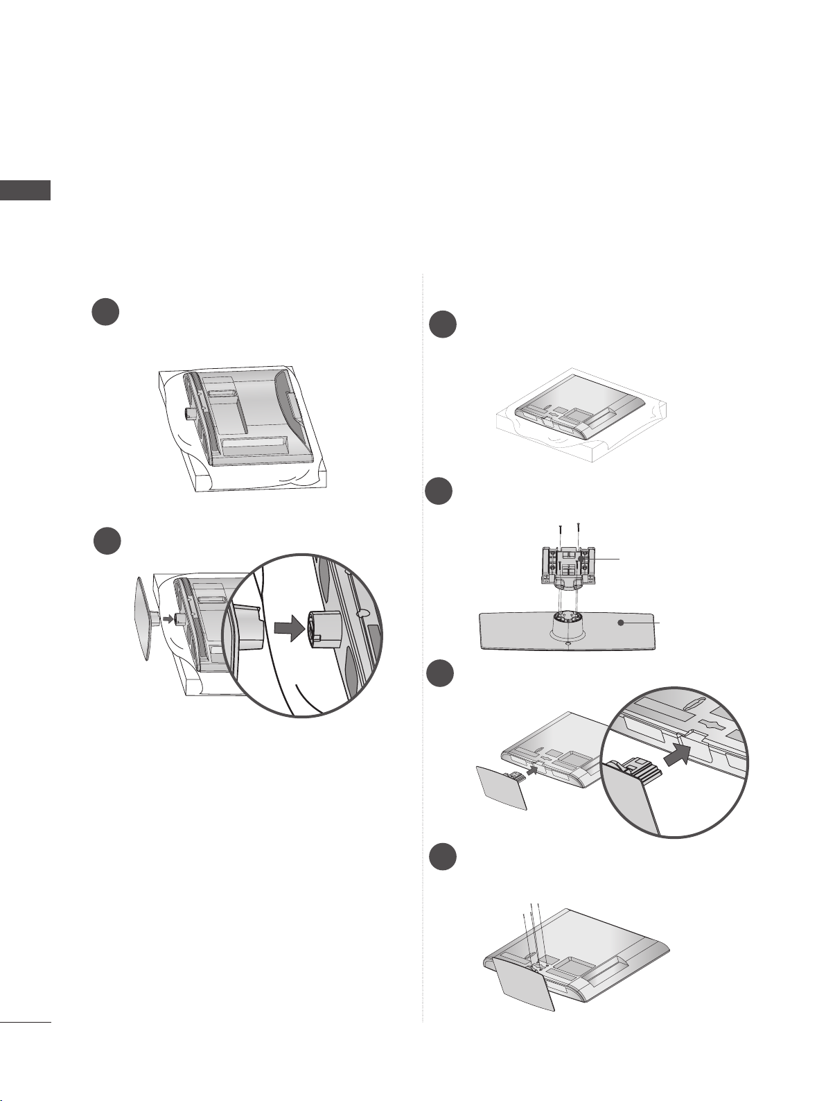
Only 26/32/37/42/47/55LE53**, 26/32LE3***
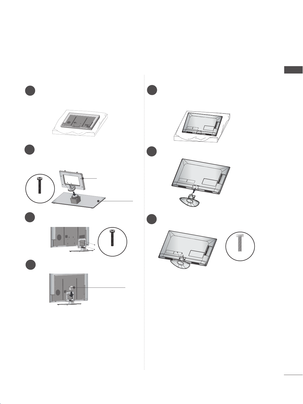
Only 22LE53**
Carefully place the TV screen side down
1
on a cushioned surface to protect the
screen from damage.
Assemble the parts of the Stand Body with
2
the Stand Base of the TV.
Stand Body
Stand Base
Assemble the TV as shown.
3
Carefully place the TV screen side down
1
on a cushioned surface to protect the
screen from damage.
Assemble the parts of the Stand Body with
2
the Stand Base of the TV.
M4 X 22(Only 32LE53**,
32LE3***)
M4 X 24 (Only 37/42LE53**)
M4 X 26 (Only 47/55LE53**)
M4 X 20
(Only 26LE53**, 26LE3***)
Assemble the TV as shown.
3
PREPARATION
Stand
Body
Stand
Base
Fix the 4 bolts securely using the holes in
4
the back of the TV.
M4 X 14
Assemble the parts of the Stand Rear
4
Cover with the TV.
Fix the 4 bolts securely using the holes in
5
the back of the TV.
M4 X 14
(Only 26LE53
26LE3***
**,
)
Stand Rear
Cover
M4 X 16 (Only
32/37/42/47/55LE53
32LE3***
**,
)
A-19
PREPARATION
■ Image shown may differ from your TV.
PREPARATION
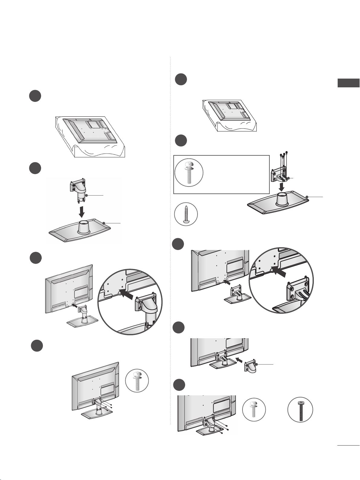
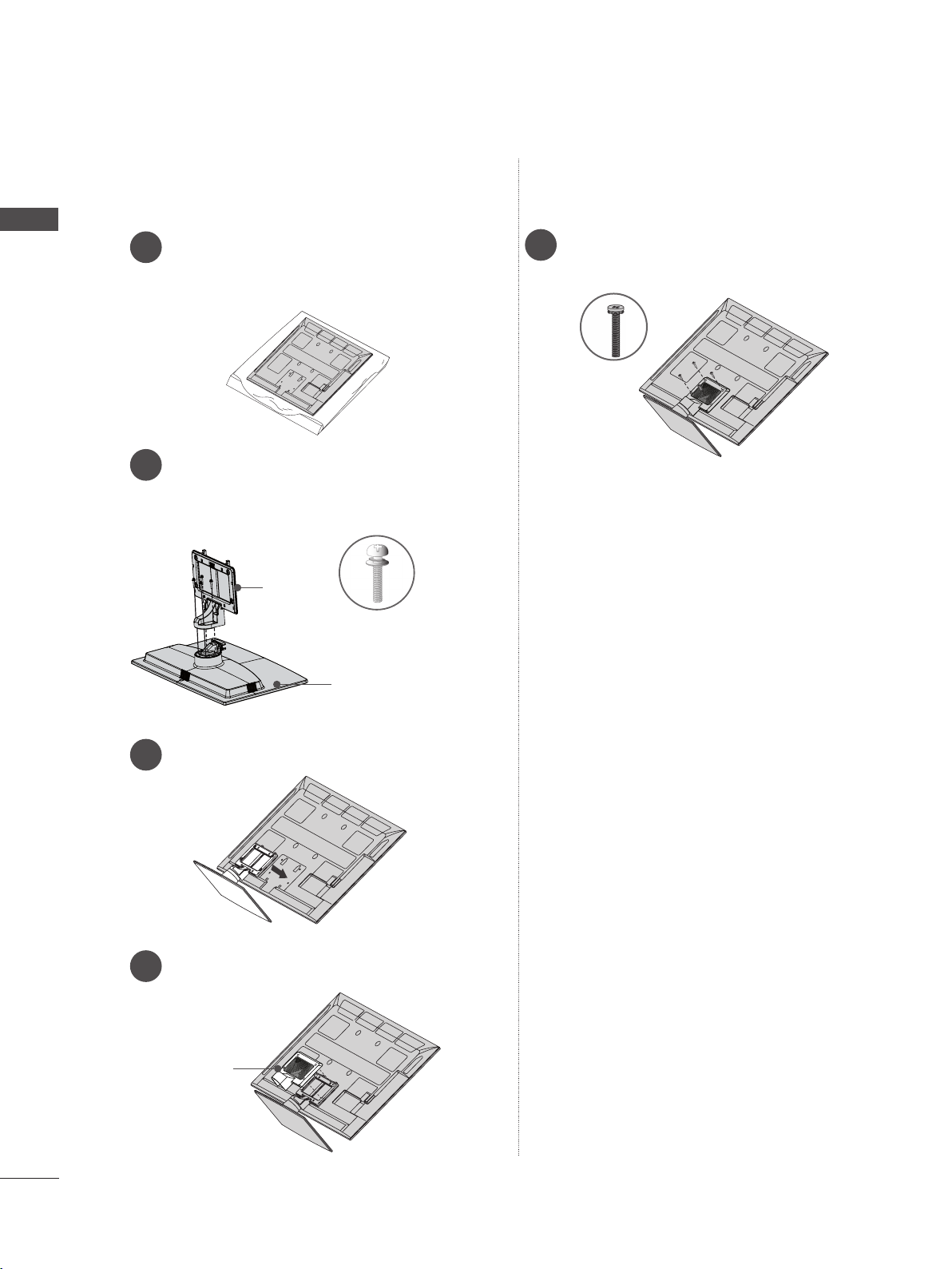
Only 32/37/42/47/55LE55**, 32/37/42/47/55LE7***, 42/47/55LE8***, 42/47/55LX6***
Carefully place the TV screen side down
1
on a cushioned surface to protect the
screen from damage.
Assemble the parts of the Stand Body with
2
the Stand Base of the TV.
At this time, tighten the screws that hold the
Stand Body on.
M4 X 16
(Only 32/37/42/47LE55**,
32/37/42/47LE7
, 42/47LX6***)
***
M4 X 20
(Only 42/47/55LE8
***
)
Assemble the parts of the Stand Rear
4
Cover with the TV.
Fix the 4 bolts securely using the holes in
5
the back of the TV.
M4 X 16
Stand Rear
Cover
M4 X 20
M4 X 24
(Only 55LE55**,
55LE7***, 55LX6***)
Assemble the TV as shown.
3
Stand
Body
Stand
Base
(Only
32/37/42/47/55LE55**,
32/37/42/47/55LE7
42/47/55LX6***)
***
(Only 42/47/55LE8
,
***
)
A-20
Only 47/55LX9***
Only 22/26LE6***
PREPARATION
Carefully place the TV screen side down
1
on a cushioned surface to protect the
screen from damage.
Assemble the parts of the Stand Body with
the Stand Base of the TV.
2
At this time, tighten the screws that hold the
Stand Body on.
Stand Body
M4 X 22
Stand Base
Fix the 4 bolts securely using the holes in
3
the back of the TV.
Carefully place the TV screen side down
1
on a cushioned surface to protect the
screen from damage.
Assemble the TV as shown.
2
Fix the 2 screws securely using the holes
3
in the back of the TV.
Assemble the parts of the Stand Rear
4
Cover with the TV.
Stand Rear
M4 X 12
M4 X 16
Cover
A-21
PREPARATION
■ Image shown may differ from your TV.
Only 32/42/47/55LE4***
PREPARATION
Carefully place the TV screen side down
1
on a cushioned surface to protect the
screen from damage.
Assemble the parts of the Stand Body with
2
the Stand Base of the TV.
At this time, tighten the screws that hold the
Stand Body on.
Stand
Body
M4 X 22(Only 32LE45
32/42/47/55LE46**
M4 X 24 (Only 42LE45**)
Stand
Base
Fix the 4 bolts securely using the holes in
5
the back of the TV.
M4 X 16
**,
)
A-22
Assemble the TV as shown.
3
Assemble the parts of the Stand Rear
4
Cover with the TV.
Stand Rear
Cover
WOOFER INSTALLATION :WHEN USING THE WALL MOUNT
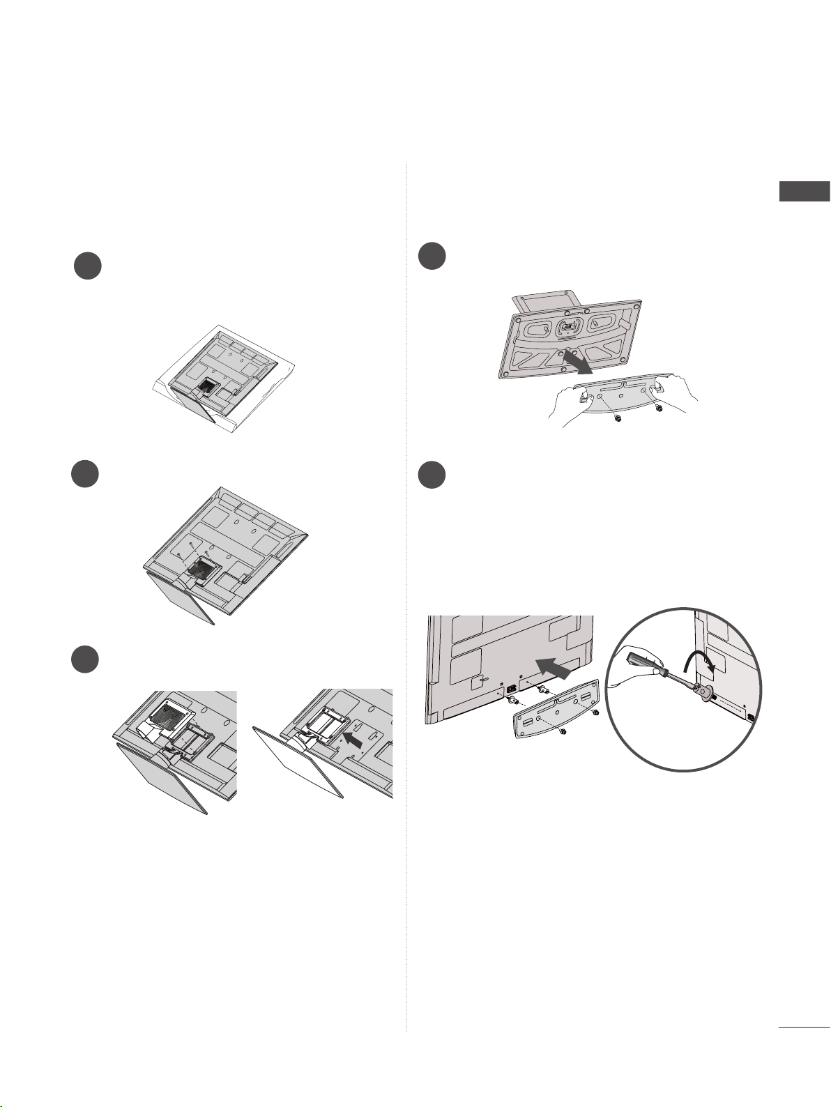
Only 32/42/47/55LE46**
PREPARATION
Carefully place the TV screen side down
1
on a cushioned surface to protect the
screen from damage.
Remove the screws from the TV.
2
Detach the Stand Rear Cover and Stand
3
from TV.
4
Detach the Woofer from the stand.
Assemble the Woofer with the TV.
5
Turn the PEM nut for the woofer using a
flathead driver and install the 2 screws as
shown.
When installing the woofer in the TV,
make sure that the power cord is not
twisted, bent or pinched.
A-23
PREPARATION
K
AC-IN
AC IN
AC IN
AC IN
AC IN
BACK COVER FOR WIRE ARRANGEMENT
■ Image shown may differ from your TV.
PREPARATION
Only 22LD3**, 22/26LE6***
Only 26/32LD3**, 32/37/42/47LD4**,
32/37/42/47/55LD6**, 32/42/46/52/60LD5**
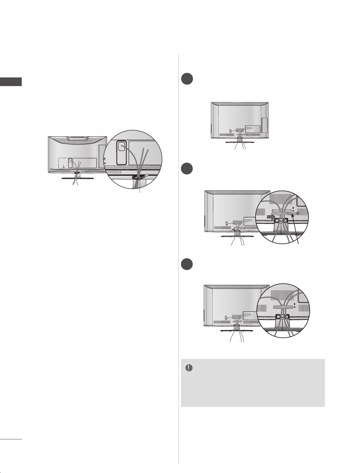
Connect the cables as necessary.
1
To connect additional equipment, see the
External equipment setup section.
After connecting the cables as necessary, install
Cable Tie as shown and bundle the cables.
AC IN
AC-IN
K
Open the Cable Management Clip as
2
shown and manage the cables.
Cable Tie
AC IN
Cable Management Clip
Fit the Cable management clip as shown.
3
AC IN
NOTE
►Do not use the CABLE MANAGEMENT CLIP
to lift the TV.
- If the TV is dropped, you may be injured or the
TV may be damaged.
A-24
■ Image shown may differ from your TV.
USB IN 2
USB IN 1
Only 22/26LE5***, 26LE3***
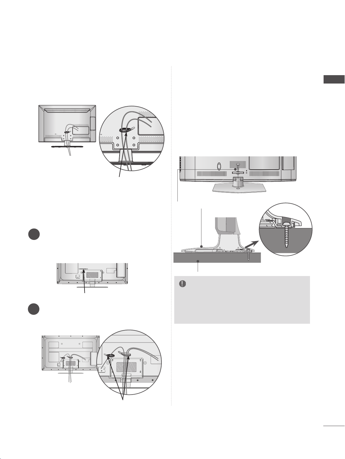
After connecting the cables as necessary,
install Cable Holder as shown and bundle the
cables.
Cable Holder
ATTACHING THE TV TO A DESK
(Only 26/32LD3**, 32/37/42LD4**,
32/42LD5
32/42/47/55LE46**, 32LE5***, 32LE7***,
32LE3***
■ Image shown may differ from your TV.
The TV must be attached to desk so it cannot be
pulled in a forward/backward direction, potentially causing injury or damaging the product. Use
only an attached screw.
**, 32/37/42LD6**, 32LE45**,
)
AC IN
CABLE MANAGEMENT
PREPARATION
Only 32/37/42/47/55LE5***,
32/37/42/47/55LE7***, 42/47/55LE8***,
42/47/55LX6***, 47/55LX9***, 32/42/47/55LE4***,
32LE3***
Secure the power cord with the Cable
1
Holder on the TV back cover.
It will help prevent the power cable from
being removed by accident.
Cable Holder
After connecting the cables as necessary,
2
install Cable Holder as shown and bundle
the cables.
1-Screw ( provided as parts of the product)
Stand
Desk
WARNING
►To prevent TV from falling over, the TV
should be securely attached to the floor/wall
per installation instructions. Tipping, shaking,
or rocking the machine may cause injury.
Cable Holder
A-25
PREPARATION
PREPARATION
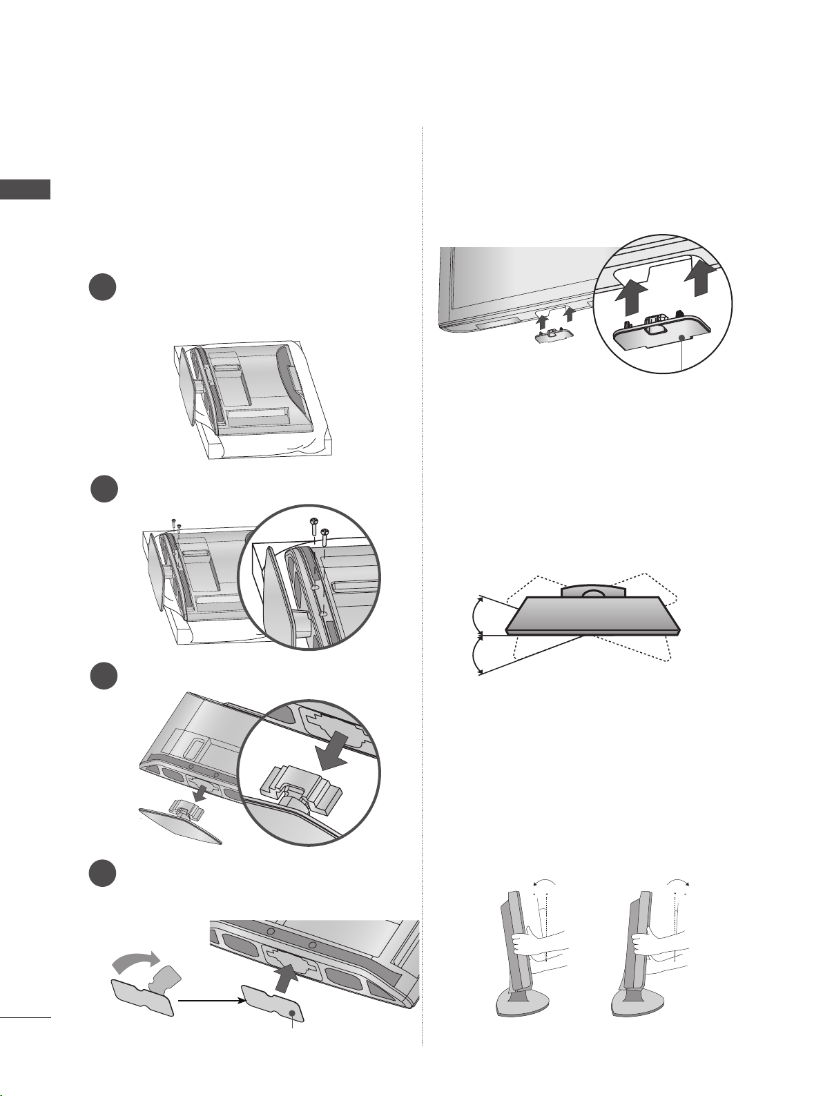
NOT USING THE DESKTYPE STAND
■ Image shown may differ from your TV.
When installing the wall-mounted unit, use the
protection cover.
Only 22LD3**
Carefully place the TV screen side down
1
on a cushioned surface to protect the
screen from damage.
Loose the bolts from TV.
2
Only 26/32LD3**, 32/37/42/47LD4**,
32/42/46/52/60LD5**, 32/37/42/47/55LD6**
Insert the Protection cover into the TV until
clicking sound.
Protection cover
SWIVEL STAND
(Except for 22LD3**, 22/26LE6***)
■ Image shown may differ from your TV.
After installing the TV, you can adjust the TV set
manually to the left or right direction by 20
degrees to suit your viewing position.
A-26
Detach the Stand from TV.
3
After removing the protection paper from
4
the protection cover, adhere it to the TV as
shown.
Protection Cover
POSITIONING YOUR DISPLAY
(Only 22LD3**)
■ Image shown may differ from your TV.
Adjust the position of the panel in various ways
for maximum comfort.
• Tilt range
0
0
12
3
 Loading...