

Page 1

MV-5 Processor
User Guide
Page 2
IMPORTANT SAFETY INSTRUCTIONS
1. Read these instructions.
2. Keep these instructions.
3. Heed all warnings.
4. Follow all instructions.
5. Do not use this apparatus near water.
6. Clean only with a dry cloth.
7. Do not block any ventilation openings. Install in
accordance with the manufacturer’s instructions.
8. Do not install near any heat sources such as
radiators, heat registers, stoves, or other
apparatus (including amplifiers) that produce
heat.
9. Do not defeat the safety purpose of the polarized or grounding-type plug. A polarized plug
has two blades with one wider than the other. A
grounding-type plug has two blades and a third
grounding prong. The wide blade or the third
prong are provided for your safety. If the provided plug does not fit into your outlet, consult
an electrician for replacement of the obsolete
outlet.
10. Protect the power cord from being walked on
or pinched, particularly at plugs, convenience
receptacles, and the point where they exit from
the apparatus.
11. Only use attachments/accessories specified by
the manufacturer.
12. Use only with the cart, stand,
tripod, bracket or table specified
by the manufacturer, or sold with
the apparatus. When a cart is
used, use caution when moving
the cart/apparatus combination
to avoid injury from tip-over.
13. Unplug this apparatus during lightning storms
or when unused for long periods of time.
14. Refer all servicing to qualified service personnel.
Servicing is required when the apparatus has
been damaged in any way, such as when a
power supply cord or plug is damaged, liquid
has been spilled or objects have fallen into the
apparatus, the apparatus has been exposed to
rain or moisture, does not operate normally, or
has been dropped.
15. Do not expose this apparatus to dripping or
splashing and ensure that no objects filled with
liquids, such as vases, are placed on the
apparatus.
16. To completely disconnect this apparatus from
the AC Mains, disconnect the power supply
cord plug from the AC receptacle.
17. The MAINS cord is intended to be the safety
disconnect device for this apparatus and shall
remain readily operable at all times.
18. Do not expose batteries to excessive heat, such
as sunshine, fire, or the like.
19. This product shall be connected to a MAINS
socket outlet with a protective earthing
connection.
This equipment has been tested and found to
comply with the limits for a Class B digital device,
pursuant to Part 15 of FCC Rules. These limits are
designed to provide reasonable protection against
harmful interference in a residential installation.
This equipment generates, uses, and radiates radio
frequency energy and, if not installed and used in
accordance with the instructions, may cause
harmful interference to radio or television
reception, which can be determined by turning
the equipment off and on. The user is encouraged
to try to correct the interference by one or more of
the following measures:
• Re-orient or relocate the receiving antenna.
• Increase the separation between the equipment
and the receiver.
• Connect the equipment into an outlet on a circuit
different from that to which the receiver is
connected.
• Consult the dealer or an experienced radio/
television technician for help.
This device complies with part 15 of the FCC
Rules. Operation is subject to the following two
conditions: (1) this device may not cause harmful
interference, and (2) this device must accept
interference received, including interference that
may cause undesired operation.
CAUTION
Changes or modifications not expressly approved
by the party responsible for compliance could void
the user's authority to operate the equipment.
Canada
This Class B digital apparatus complies with
Canadian ICES-003.
Cet appareil numérique de la classe B est conforme à la norme NMB-003 du Canada.
WARNING
To reduce the risk of fire or electric
shock, do not expose this apparatus
to rain or moisture.
The lightning flash with arrowhead symbol, The exclamation point within an equilateral
within an equilateral triangle, is intended to
alert the user to the presence of uninsulated
“dangerous voltage” within the product’s
enclosure that may be of sufficient magnitude
to constitute a risk of electric shock to persons.
triangle is intended to alert the user to the
presence of important operating and
maintenance (servicing) instructions in the
literature accompanying the product.
Page 3

Lexicon Inc.
3 Oak Park Drive
Bedford, MA 01730-1413 USA
Tel 781-280-0300
Fax 781-280-0490
www.lexicon.com
Lexicon, “Logic 7”, and the L7 logo are registered trademarks of Harman International Industries, Inc.
Manufactured under license from Dolby Laboratories. “Dolby”, “Pro Logic”, and the double-D symbol are trademarks of Dolby
Laboratories.
“DTS” and “DTS-ES | Neo:6” are registered trademarks of DTS, Inc. and “96/24” is a trademark of DTS, Inc.
“Faroudja” and “DCDi by Faroudja” are trademarks of Genesis Microchip, Inc.
“HD-DVD” is a trademark of the DVD Format/Logo Licensing Corporation (DVD FLLC).
“HDMI”, the HDMI logo, and “High-Definition Multimedia Interface” are trademarks or registered trademarks of HDMI Licensing
LLC.
“iPod” and “iTunes” are trademarks of Apple Computer, Inc.
“SACD” is a trademark of Sony Electronics, Inc.
“Windows” is a trademark of Microsoft, Inc.
“DLP” and “Digital Light Processing” are trademarks of Texas Instruments, Inc.
Customer Service
Telephone: 781-280-0300
Sales Fax: 781-280-0495
Service Fax: 781-280-0499
Part No. 070-18137 | Rev 0 | 07/07
Other company and product names may be trademarks of the respective companies with which they are associated.
© 2007 Harman Specialty Group and Harman International Industries, Incorporated. All rights reserved.
Harman Specialty Group is a wholly-owned company of Harman International, Inc.
This document should not be construed as a commitment on the part of Harman Specialty Group. The information it contains is
subject to change without notice. Harman Specialty Group assumes no responsibility for errors that may appear within this
document.
Page 4

Introduction Lexicon
DOCUMENTATION CONVENTIONS
This document contains general safety, installation and operation instructions for the MV-5 Processor. It is important to read this user guide
before attempting to use the product. Pay particular attention to safety instructions.
Note: This manual is not intended as a general reference guide for home theater systems. If you’re uncertain how to proceed in setting up or maintaining
your system, seek the advice of a professional installer or ask your dealer for their recommendations.
All graphics of the product are included for reference only and may not completely reflect the physical product that is shipped.
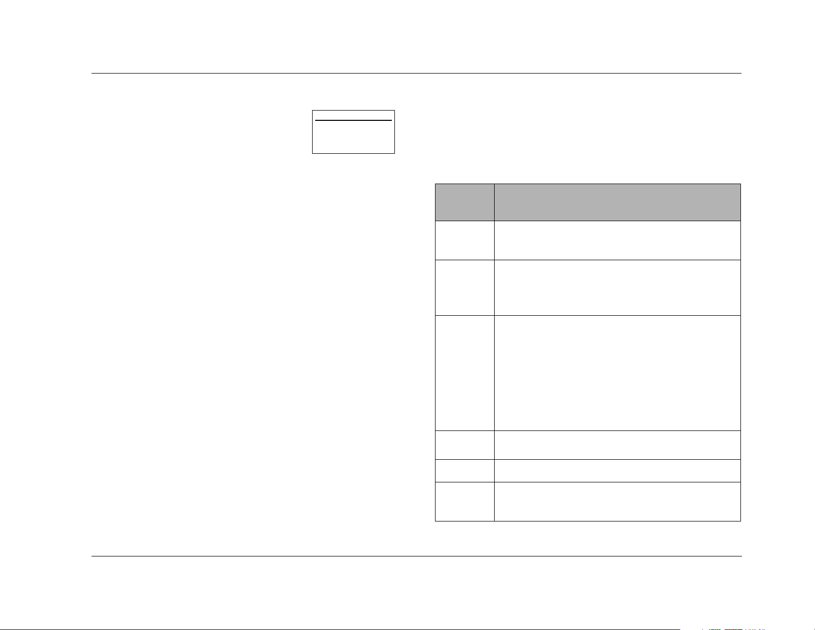
The following symbols are used in the document:
Appears on the component to indicate the
presence of uninsulated, dangerous voltage
inside the enclosu
sufficient to constitute a risk of shock.
Appears on the component to indicate important
operating and maintenance instructions in the
accompanying literature.
re – voltage that may be
WARNING
CAUTION!
Note:
ii
Calls attention to a procedure, practice,
condition or the like that, if not correctly
performed or adhered to, could result in injury or
death.
Calls attention to a procedure, practice,
condition or the like that, if not correctly
performed or adhered to, could result in damage
or destruction to part or all of the product.
Calls attention to information that is essential to
highlight.
Page 5

MV-5 Introduction
Table of Contents
Documentation Conventions........................................................ ii
Getting Started
About the MV-5 ........................................................................ 1-2
Product Registration..................................................................1-2
Highlights .................................................................................1-2
What’s in the Box......................................................................1-3
Available Options ......................................................................1-3
D-1 iPod Docking Station Option .......................................... 1-3
RF-1 Receiver Option ............................................................. 1-3
Installation Considerations.........................................................1-4
Remote Control Battery Installation ...........................................1-4
Basic Operation
Front Panel Overview ................................................................ 2-2
Rear Panel Overview.................................................................. 2-5
PC & Dock Overview.................................................................2-8
Remote Control Overview ......................................................... 2-8
Operation Considerations ...................................................... 2-8
MV-5 Menu Overview ........................................................... 2-9
Menu Navigation .................................................................. 2-9
........................................................................................... 2-10
Remote Control Buttons ...................................................... 2-10
Menu Options ..................................................................... 2-11
Menu Item Selection ........................................................... 2-11
Remote Control Light Button .............................................. 2-11
Command Matrix ............................................................... 2-11
Setup
Setup ........................................................................................ 3-2
Display Setup ............................................................................3-3
Speaker/EQ Setup .....................................................................3-5
Manual .................................................................................. 3-6
Semi Autocal.......................................................................... 3-6
Full Autocal ............................................................................ 3-6
Manual Speaker Setup...............................................................3-8
Speakers Menu ..................................................................... 3-9
Speaker Distances Menu ..................................................... 3-10
Output Levels Menu ............................................................ 3-11
Input Setup ............................................................................. 3-13
Advanced Video .................................................................. 3-19
Listening Modes......................................................................3-22
Selecting a Listening Mode ................................................. 3-22
DTS + Dolby Listening Modes ............................................. 3-22
Available Listening Modes ................................................... 3-23
Listening Mode Descriptions ............................................... 3-26
5.1-channel & 7.1-channel Direct Inputs ............................. 3-28
DTS & Dolby Status Displays ............................................... 3-28
Surround Configuration .......................................................... 3-29
Dolby Configuration ............................................................... 3-31
Mute Levels............................................................................. 3-32
Power On Settings .................................................................. 3-32
Audio Controls & Video Status
Audio Controls .......................................................................... 4-2
Video Status .............................................................................. 4-4
PC & Dock Controls
PC & Dock Overview.................................................................5-2
PC Controls............................................................................... 5-2
Setting Up to Play ................................................................. 5-2
Playing PC Media .................................................................. 5-3
Dock Functionality ....................................................................5-4
Connecting the Dock to the MV-5 ........................................ 5-4
iii
Page 6

Introduction Lexicon
Selecting the Correct iPod Insert ............................................5-4
Docking the iPod ...................................................................5-5
Dock 2-line Display Characteristics ........................................5-5
Controlling the iPod with the MV-5 .......................................5-6
Charging the iPod .................................................................5-6
Removing the iPod ................................................................ 5-6
Zone 2 iPod Controls ............................................................. 5-7
Troubleshooting & Maintenance
Troubleshooting ........................................................................6-2
MV-5 Error Messages.................................................................6-7
Video Error Messages ............................................................. 6-7
Autocal Error Messages ..........................................................6-8
Video Resolutions Table ...........................................................6-10
Routine Maintenance...............................................................6-12
Restoring Factory Default Settings ...........................................6-12
Appendix A
Specifications.............................................................................A-2
Declaration of Conformity .........................................................A-4
Appendix B
Main Menu: Audio Controls ......................................................B-2
Main Menu: Video Status ..........................................................B-2
Main Menu: Setup.....................................................................B-3
Setup Menu: Display Setup ...................................................B-4
Setup Menu: Surround Config ............................................... B-4
Setup Menu: Speaker/EQ Setup
Setup Menu: Input Setup ......................................................B-6
.............................................B-5
Lock Feature ..........................................................................C-6
Advanced Customizing Tools ................................................C-6
Erasing Commands .............................................................C-13
Restoring Factory Default Settings .......................................C-14
Optional RF-1 Receiver ........................................................... C-14
Using the 3-Digit Code Library ............................................... C-15
3-Digit Pre-programmed Codes ...........................................C-15
Appendix D
Installation Worksheet ............................................................ D-2
3-Digit Pre-programmed Codes Worksheet .............................. D-6
Index
Appendix C
Remote Control Programming.................................................. C-2
Remote Control Light Button .................................................C-2
Transmitting Icon ..................................................................C-2
Setting Up the Remote Control .............................................C-3
iv
Page 7

1
Getting Started
About the MV-5 ......................................................................... 1-2
Product Registration................................................................... 1-2
Highlights .................................................................................. 1-2
What’s in the Box....................................................................... 1-3
Available Options ....................................................................... 1-3
D-1 iPod Docking Station..........................................................................1-3
RF-1 Receiver............................................................................................. 1-3
Installation Considerations.......................................................... 1-4
Remote Control Battery Installation ............................................ 1-4
Page 8

Getting Started Lexicon
ABOUT THE MV-5
Thank you for purchasing the MV-5 Processor, a multi-faceted audio
and video preamplifier with built-in processing. In addition, the
MV-5 can accommodate a pair of HDMI source devices and can
connect directly to a PC via USB, enabling the control and playback
of streaming audio files. With the optional dock accessory, iPod
owners can even connect and play their iPod through the MV-5.
The MV-5 is designed to serve as the control center for your home
theater system. A landmark product for Lexicon, the MV-5 offers
capabilities never before offered as well as breaking ground with
several brand new features. The MV-5 represents a new age in
audio and video processing equipment from Lexicon.
We hope you enjoy your Lexicon experience!
PRODUCT REGISTRATION
Please register your MV-5 Processor online at
www.harmanspeciatlygroup.com/registration/ within 15 days of
purchase. Retain the sales receipt as proof of warranty coverage.
HIGHLIGHTS
• 12 configurable inputs, 8 channels, 2 audio zones
• Logic 7 audio processing
• Automatic EQ and speaker calibration (microphone included)
• HDMI inputs and output
• Faroudja
• RS-232 control, rear panel IR input, 2 trigger outputs
• 7.1-channel analog input array
• Universal pre-programmed and learning remote control
• PC-compatible media player support via USB connector
• iPod support (with optional accessory
• RF remote control (with optional accessory)
®
video processing
1-2
Page 9

MV-5 Getting Started
WHAT’S IN THE BOX
The following items are included with the MV-5 Processor:
One User Guide (this document)
One Remote Control
Four AAA Batteries (for use with Remote Control)
One Microphone
One Microphone Rod
One North American Power Cord
Two Export Power Cords
AVAILABLE OPTIONS
The following accessories are available for purchase as options to
the MV-5 Processor:
• D-1 iPod Docking Station, Part No. 021-18138, allows an iPod
to be connected and controlled by the MV-5 Processor.
• RF-1 Receiver, Part No. 021-18005, allows the remote control
to operate via RF (Radio Frequency), giving the remote a
broader operating range.
included) with the sonic power of your Lexicon Processor. Just one
simple connection and you’re ready to go!
• Single connection to your Lexicon Processor
• Plays audio from an iPod through your Lexicon Processor
• Controls your iPod through your Lexicon Processor
• Simple track selection with on-screen navigation
• Charges the iPod
RF-1 RECEIVER OPTION
The optional RF-1 Receiver utilizes the RF feature of the Lexicon remote
control, allowing you to control components that are completely
out-of-sight, up to 100-feet away. Since the RF-1 Receiver picks up the
RV-5’s remote control radio frequency signal, the remote control no
longer needs to be pointed directly at the components to control
them. Now you can close your entertainment center doors, hide your
components, and still control them with ease.
The RF-1 Receiver accessory requires no setup to the Lexicon remote
control in order for the feature to work - you need only place the RF-1
Receiver in the rack or cabinet, or attach an emitter to the MV-5 front
panel over the IR receiver. Every time a command is sent from the
remote control, it sends both a standard IR and an RF signal. The RF-1
Receiver automatically receives the remote’s radio signals and
translates them into the infrared commands that control the
components.
D-1 iPOD DOCKING STATION OPTION
The optional D-1 iPod Docking station allows you to enter a new
world of listening enjoyment made possible by combining the
increased storage capacity and playback flexibility of an iPod® (not
1-3
Page 10

Getting Started Lexicon
INSTALLATION CONSIDERATIONS
The MV-5 requires special care during installation to ensure optimal
performance. Pay particular attention to the instructions below and
to other precautions that appear throughout this user guide.
DO install the MV-5 on a solid, flat, level surface such as a table or
shelf.
DO select a dry, well-ventilated location out of direct sunlight.
DO NOT expose the MV-5 to high temperatures, humidity, steam,
smoke, dampness or excessive dust. Avoid installing the MV-5 near
radiators or stacking the MV-5 over other heat-producing
equipment such as a power amplifier.
DO NOT place the MV-5 on a thick rug or carpet, or cover the RV-5
with a cloth, as this might prevent proper cooling.
DO NOT place the MV-5 on a windowsill or any location exposed
to direct sunlight.
DO NOT obstruct the front panel IR receiver window. The remote
control must be in line of sight with the IR receiver for proper
operation (unless using the optional RF-1 Receiver).
REMOTE CONTROL BATTERY
INSTALLATION
The remote control requires four AAA batteries. The batteries
should be replaced as needed. Alkaline batteries, which last longer
without leaking, are recommended. When battery power is low, the
remote control enters a low-voltage condition, preventing it from
operating the MV-5. When this occurs, replace the batteries.
Normal operation will resume when new batteries are installed.
Note: The Remote Control will not lose any custom settings if the batteries
run out. All custom settings are stored in non-volatile FLASH memory.
To replace the remote control batteries:
1. Locate the battery compartment on the back of the remote
control. Press the tab and lift the cover away from the remote
control.
2. Remove old batteries, if applicable.
3. Observing the proper polarity, insert four AAA batteries.
4. Align the cover over the battery compartment and gently press
down until it snaps back into place.
5. Properly dispose of the old batteries.
DO NOT install the MV-5 on a surface that is unstable or unable to
support all four feet.
CAUTION!
Before moving the MV-5, power the unit off using the rear
panel power switch and unplug the power cord from the
wall outlet.
1-4
Page 11

2
Basic Operation
Front Panel Overview ................................................................. 2-2
Rear Panel Overview................................................................... 2-5
PC & Dock Overview.................................................................. 2-8
Remote Control Overview .......................................................... 2-8
Operation Considerations.......................................................................... 2-8
MV-5 Menu Overview ............................................................................... 2-9
Menu Navigation ...................................................................................... 2-9
Remote Control Buttons.......................................................................... 2-10
Menu Options.........................................................................................2-11
Menu Item Selection ............................................................................... 2-11
Remote Control Light Button ..................................................................2-11
Command Matrix ................................................................................... 2-11
Page 12
Basic Operation Lexicon
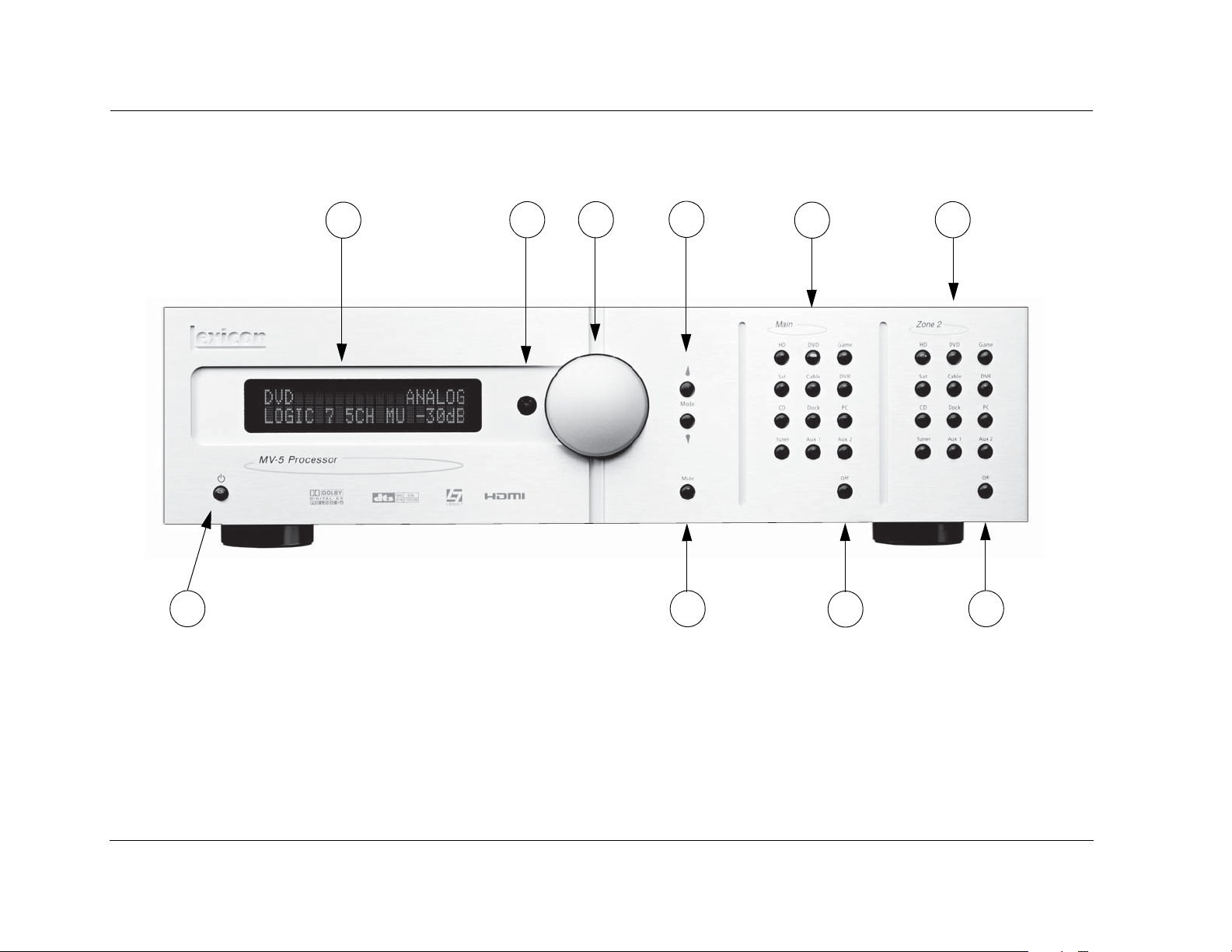
FRONT PANEL OVERVIEW
The MV-5 is shown below. The numbers in the front panel illustration correspond with the numbered items in the text.
10 9
1. Front Panel Display
2. IR Receiver
1
2 3
4
5
8
6. Zone 2 Input Selection Buttons
7. Zone 2 Off Button
6
7
3. Volume Knob
4. Mode Buttons
5. Main Zone Input Selection Buttons
2-2
8. Main Zone Off Button
9. Mute Button
10. ON/Standby Button
Page 13

MV-5 Basic Operation
1. FRONT PANEL DISPLAY
Use the front panel 2-line display to view the current input source,
input type, listening mode, and volume level. The 2 x 20 character
display also functions as a display for messages and menus, one line
at a time.
2. IR RECEIVER
The IR receiver receives infrared commands from the MV-5 remote
control. Blocking the IR receiver will prevent the remote control
from functioning properly (unless using the optional RF-1
Receiver).
3. VOLUME KNOB
Use the volume knob to adjust the volume level. The adjustable volume
range is -80 dB to +10 dB in 1 dB increments.
Note: The maximum volume level may be lower than +10 dB due to the
output level settings of the speakers. Refer to Section 3: Setup for more
information on setting the speaker output levels.
To adjust the Main Zone volume level:
Rotate the volume knob clockwise to increase or counter-clockwise
to decrease the volume level in 1dB increments. The current
volume level is indicated on the bottom right side of the 2-line front
panel display.
2. While holding down the Zone 2 input button, rotate the volume
knob clockwise to increase the volume or counter-clockwise to
decrease the volume. On the front panel 2-line display, the
bottom left side displays that Zone 2 is selected and the bottom
right side indicates the current volume level.
Note: If you attempt to set the volume higher than the maximum or lower
than the minimum volume levels, the displayed volume level flashes.
4. MODE BUTTONS
Use the Mode buttons to scroll to the previous () or next ()
available listening mode. Scrolling the Mode button reveals the
entire list of listening modes available for the currently selected
input and mode family. For more information on selecting listening
modes, refer to Section 3: Setup.
5. MAIN ZONE INPUT SELECTION BUTTONS
Individually select each of the twelve inputs available in the Main
Zone. When an input is selected, a blue LED lights in the
corresponding input selection button. When the Main Zone is
deactivated, pressing a Main Zone input selection button activates
the corresponding input in the Main Zone.
When the MV-5 is in Standby, pressing a Main Zone input selection
button powers on the MV-5, selects the input in the Main Zone,
and turns off Zone 2.
To adjust the Zone 2 volume level:
1. Press and hold the front panel Zone 2 input selection button that
corresponds with the current input source. For instance, if DVD is
the current Zone 2 input source, press and hold the DVD input
selection button in the Zone 2 area of the front panel.
6. ZONE 2 INPUT SELECTION BUTTONS
Individually select each of the twelve inputs available in Zone 2.
When an input is selected, an amber LED lights on the
corresponding input selection button. When Zone 2 is deactivated,
pressing a Zone 2 input selection button activates the
corresponding input in Zone 2.
2-3
Page 14

Basic Operation Lexicon
When the MV-5 is in Standby, pressing a Zone 2 input selection
button powers on the MV-5, selects the input in Zone 2, and turns
off the Main Zone.
7. ZONE 2 OFF BUTTON
Deactivates Zone 2. When Zone 2 is off, the Zone 2 OFF button on
the front panel lights red.
8. MAIN ZONE OFF BUTTON
Deactivates the Main Zone. When the Main Zone is off, the Main
Zone OFF button on the front panel lights red.
Note: Activating the Main Zone OFF button on the front panel turns off
the audio, however the video continues to be output through both the
analog and HDMI video outs. If using the HDMI Video In connection, only
the HDMI video is output. If the analog Video In is used, then both analog
and HDMI video is output. Main Zone OSD (On-Screen Display) menus
are also still available.
9. MUTE BUTTON
The LED in the MUTE button lights red when the Main Zone mute is
active, green when the Zone 2 mute is active, and amber when
both Zones are muted. The volume can also be muted by using the
MUTE button on the remote control, which functions in the same
manner. However, the remote only mutes Zone 2 if the touch
screen is in the “Zone 2” menu layer.
10. ON/STANDBY BUTTON
Toggles the MV-5 between On and Standby. The rear panel Power
Switch must be set to the ON position for the Standby button to be
active. When the MV-5 is in the standby mode, pressing the
Standby button turns the unit on and changes the light in the
Standby button from red to blue. Power is still supplied to the
MV-5 when standby mode is activated.
When the rear panel Power Switch is set to the ON position or AC
power is applied or restored, the MV-5 automatically enters the
standby mode.
Note: When taken out of standby, the MV-5 activates the Zone inputs
that were active in the previous operating session.
Mutes the Main Zone and Zone 2 volumes. Press the MUTE button to
mute the Main Zone volume level; “MUTE ON” appears in the 2-line
and OSD displays. Press the MUTE button again to restore the volume
to its original level. If a front panel Zone 2 input button is held down,
then pressing the MUTE button on the front panel will mute the Zone
2 output.
On the remote control, pressing the volume button once while the
volume is muted, turns off mute. Pressing and holding the Volume
button, while the sound is muted, resets to the original pre-mute
volume level and then increases or decreases the volume from that
point, turning off mute.
2-4
Page 15
Basic Operation Lexicon
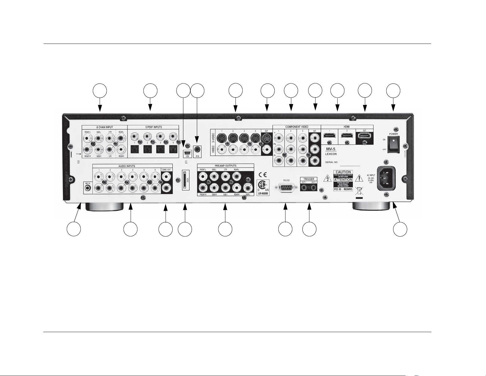
REAR PANEL OVERVIEW
The MV-5 rear panel is shown below. The numbers in the rear panel illustrations correspond with the numbered items in the text.
1 2
19
1. 8-CH Analog Audio Input Connector
Array
2. Digital Audio Input Connectors
3. USB Connector
4. IR Input Connector
5. S-Video/Composite Input Connectors
6. S-Video/Composite Ouput Connectors
18 15
3
4
17
16
7. Component Video Input Connectors
8. Component Video Output Connector
9. HDMI Input Connectors
10. HDMI Output Connector
11. Power Switch
12. AC Input Connector
13. Trigger Output Connectors
5
6
14
7
8
9
13
14. RS-232 Connector
15. Preamplifier Outputs
16. Dock Connector
17. Zone 2 Audio Output Connectors
18. Stereo Analog Audio Input Connectors
19. Microphone Input Connector
10
11
12
2-5
Page 16

Basic Operation Lexicon
CAUTION!
Never make or break connections to the MV-5 unless the
MV-5 and all associated components are powered off.
1. 8-CH ANALOG AUDIO INPUT CONNECTOR
ARRAY
Provides 8-channel analog audio input via eight RCA connectors
labeled Front L/R, Center, LFE, Side L/R and Rear L/R. These inputs
are used to connect source devices such as high-resolution DVD
players, DVD-Audio, or SACD players with discrete analog audio
outputs. Depending on the source device in use, all eight
connectors may be used, although only the Front L/R, Center, Side
L/R, and LFE are required for 5.1 analog audio signals.
2. DIGITAL AUDIO INPUT CONNECTORS
Provide digital audio input via four S/PDIF optical (TOSLINK) and four
S/PDIF coaxial (RCA) input connectors. Connectors are compatible
with most PCM, Dolby Digital, and DTS sources.
3. USB CONNECTOR
connection) or mono plug (Tip/Sleeve connection).
5. S-VIDEO/COMPOSITE INPUT CONNECTORS
Provide the S-Video & Composite analog video inputs. Four
composite video connectors labeled 1 to 4 and four S-Video
connectors labeled 1 to 4 are available.
6. S-VIDEO/COMPOSITE OUTPUT CONNECTORS
Provide the S-Video & Composite video outputs. One composite
video connector and one S-Video connector are available.
7. COMPONENT VIDEO INPUT CONNECTORS
Provide inputs that can be used with any source device that is
equipped with analog Y/Pr/Pb or RGB component video outputs.
Three inputs, labeled Component Video 1 to 3, are supplied.
8. COMPONENT VIDEO OUTPUT CONNECTOR
Provides one component output that can be used with any device that
is equipped with analog Y/Pr/Pb or RGB component video intputs.
Provides a USB port to connect to a PC computer, enabling the user
to listen to audio from the computer through the MV-5 Processor.
The USB connector port is a “mini B” connector and requires a USB
cable (not included). See Section 5: PC & Dock Controls for more
information on the playback of computer audio.
4. IR INPUT CONNECTOR
Accepts input of IR signals from infrared distribution equipment via
one 3.5mm jack that accepts a stereo plug (Tip/Ring/Sleeve
2-6
9. HDMI INPUT CONNECTORS
Provide two HDMI inputs for devices such as a DVD player or HDTV
tuner.
10. HDMI OUTPUT CONNECTOR
Provides one HDMI output for HDMI-equipped video monitors.
Page 17

MV-5 Basic Operation
11. POWER SWITCH
Use the Power Switch to connect or disconnect power from the AC
Input connector to the MV-5 Processor. When the MV-5 is powered
on, the front panel Standby button or remote control ON & OFF
buttons can be used to activate and deactivate standby mode. When
the MV-5 is powered off via the rear panel switch, the standby and
ON modes are not available.
12. AC INPUT CONNECTOR
Provides power to the MV-5 through the supplied power cord.
13. TRIGGER OUTPUT CONNECTORS
Provide a 12V DC output to control connected components. Two
trigger output connectors are available as 3.5 mm mono mini
phone jacks. The OUT 1 connector is the power trigger and is not
configurable; it is activated when the MV-5 is powered on or taken
out of Standby mode, and deactivated when the MV-5 is powered
off, either from the rear panel or by putting the MV-5 into Standby
mode. The OUT 2 connector can be configured independently for
each input, refer to Section 3: Setup for more information on how to
configure the OUT 2 trigger.
Note: The OUT 2 trigger is referred to as “TRIGGER 2” in the Input Setup
menu.
15. PREAMPLIFIER OUTPUTS
Provide output for external power amplifiers for applications that
require them.
16. DOCK CONNECTOR
Provides an interface for an iPod, which can then be accessed
through the MV-5 rear panel. To use this feature, the D-1 Dock
option must be installed to the DOCK connector. With a
compatible iPod connected to the MV-5, selecting the DOCK input
allows you to play audio files from the iPod. You can view and
navigate through the iPod menus using the MV-5 remote control.
For more information on the Dock option and how to use your
MV-5 with an iPod, refer to Section 5: PC & Dock Controls.
17. ZONE 2 AUDIO OUTPUT CONNECTORS
Provide preamplifier audio outputs for Zone 2.
18. STEREO ANALOG AUDIO INPUT CONNECTORS
Provide stereo analog audio input. Six stereo analog audio input
RCA connectors labeled 1 to 6 are available.
19. MICROPHONE INPUT CONNECTOR
14. RS-232 CONNECTOR
The RS-232 serial connector provides serial remote control through a
standard RS-232 connection. Refer to the Lexicon website
(www.lexicon.com) for more details on controlling the MV-5 Processor
via the RS-232 connection.
Provides a microphone input for system calibration. The
microphone input is only for use with the supplied microphone
during the system calibration process. See Section 3: Setup for more
information regarding system calibration and setup.
2-7
Page 18

Basic Operation Lexicon
PC & DOCK OVERVIEW
The PC & Dock inputs are the only “hard-wired” inputs in the MV-5
Processor. Unlike the other inputs, both have very specific
audio-only functionality.
The PC input is tied to the USB input on the rear panel and is for use
with media player software on a connected PC computer. The Dock
input is for use with the optional D-1 Dock accessory and is tied to
the DOCK input on the rear panel. This input is only for use with
iPod players.
While both of these inputs have devoted Remote Control menu
controls, there are NO front panel controls for use with the PC and
DOCK inputs.
For more information about the PC & Dock operation, refer to
Section 5: PC & Dock Controls.
REMOTE CONTROL OVERVIEW
The MV-5 Processor remote control provides full operation of the
MV-5 including commands, such as menu navigation, that are not
available from the front panel. It is also designed to provide control
for the entire home theater system. This section provides a brief
overview of the remote control functions used to control the MV-5
Processor. For detailed universal remote control operation,
programming instructions, and manufacturing codes, refer to
Appendix C.
OPERATION CONSIDERATIONS
The following factors can improve or impede remote control
operation.
Note the following before operating the MV-5 remote control:
• The remote control must be in line-of-sight with the front panel
IR receiver (unless using the optional RF-1 Receiver). Eliminate
obstructions between the remote control and the IR receiver.
The remote control may become unreliable if strong sunlight or
fluorescent light shines on the MV-5 IR receiver.
• For optimal performance, position the remote control within a
30-degree angle no more than 40 to 60 feet (12.2m to 18.3m)
from the MV-5. Placing the MV-5 inside a smoked glass cabinet
will reduce the remote control range.
• Remote controls for different components can interfere with
one another. Avoid using remote controls for different
components at the same time.
• Remote control batteries should be replaced as needed.
2-8
• To control the MV-5, the touch screen of the remote control
must be in the “LEX” or “ZONE 2” menu layers. The Volume +/
- and Mute controls, however, are always active, regardless of
the active menu layer. The remote control ships from the
factory set to the “MAIN” menu layer.
Page 19
MV-5 Basic Operation
MV-5 MENU OVERVIEW
When the remote control touch screen is in the
“LEX” or “ZONE 2” menu layers, pressing
MENU or SELECT on the MV-5 remote control
accesses the menu controls for the MV-5
Processor. The MAIN MENU is the root
directory of the MV-5 menu structure and has three branches: AUDIO
CONTROLS, VIDEO STATUS, and SETUP.
Note: The DVD menu layer of the touch screen controls the Lexicon RT-20
and RT-10, if installed.
The AUDIO CONTROLS menu controls the audio-specific parameters,
such as treble and bass, as well as providing an audio status menu.
Refer to Section 4: Audio Controls & Video Status for more
information.
The VIDEO STATUS menu is an information-only menu identifying
the current video status of the MV-5 Processor. For more information, refer to Section 4: Audio Controls & Video Status.
The SETUP menu controls all aspects of setting up the MV-5 Processor.
Refer to Section 3: Setup for more information.
MAIN MENU
AUDIO CONTROLS
VIDEO STATUS
SETUP
MENU NAVIGATION
Use the remote control arrow buttons to navigate the MV-5 menu
structure, shown in detail in Appendix B. The Command Matrix
Table located later in this chapter indicates the navigation
commands that the remote control buttons perform when the MV5 command bank is activated by selecting the “LEX” or “ZONE 2”
options on the remote control touch screen.
Arrow
Navigation Functions
(for “LEX” and “ZONE2” menu layers)
When a menu is open, press the remote control arrow to
select the highlighted menu parameter. The menu parameter
will blink to indicate that it is selected.
When a menu is open, press the arrow to close the current
menu and, in most cases, open the previous menu. Subsequent
presses continue to close the current menu and open the
previous menu until the MAIN MENU is closed.
When a menu is open, press the and arrow buttons to scroll
upward and downward through the complete list of menu parameters. The highlighted menu item appears in the front panel
display. All menu items appear in the OSD. The cursor
automatically wraps to the next menu parameter when the first or
last menu item is passed.
The MV-5 menu structure can be viewed on the OSD (On-Screen
Display), which is a 480i or 480p video output signal to your monitor,
or on the front panel 2-line display, which displays the menus one line
at a time using the remote control navigation controls. The front panel
2-line display can also be viewed on the OSD, in 480i resolution only.
Note: When the MV-5 menu structure is entered, most front panel buttons
and the remote control buttons are disabled until the menu structure is
exited. The exceptions are the Volume Knob and Standby Button on the
front panel and the remote control Volume, Mute, and OFF buttons. Note
also that the disabled condition of the remote control only affects the
“LEX” and “ZONE 2” menu layers.
SELECT
MENU
EXIT
When a menu parameter is selected and blinking, press the and
arrow buttons to scroll through the available parameter
options.
Press the SELECT button to open the menu structure, open a
menu branch, or select a menu parameter.
Press the MENU button to open the menu structure.
When the menu is open, press the EXIT button to leave the menu.
Unlike the arrow button which closes a menu layer, the EXIT
button completely closes the menu structure.
2-9
Page 20
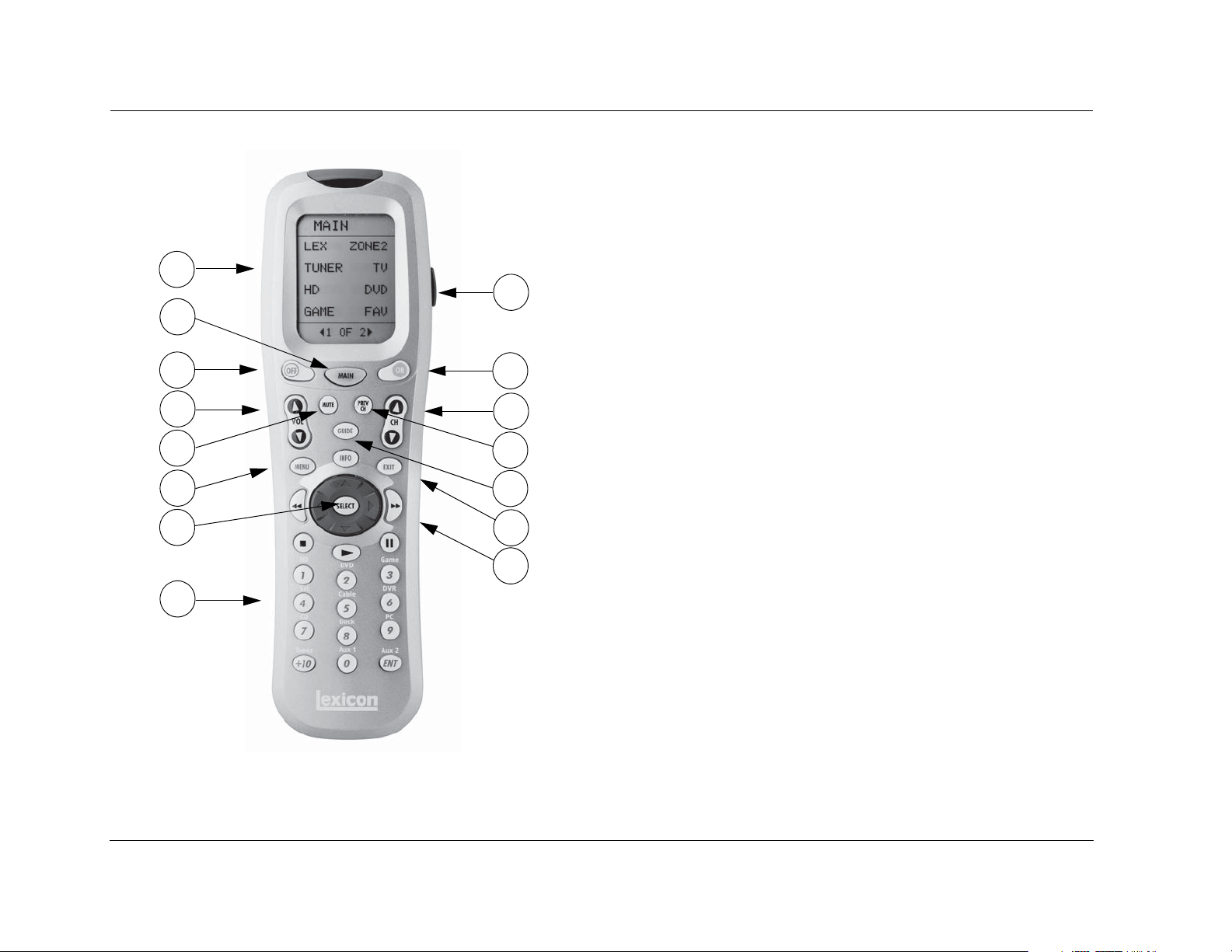
Basic Operation Lexicon
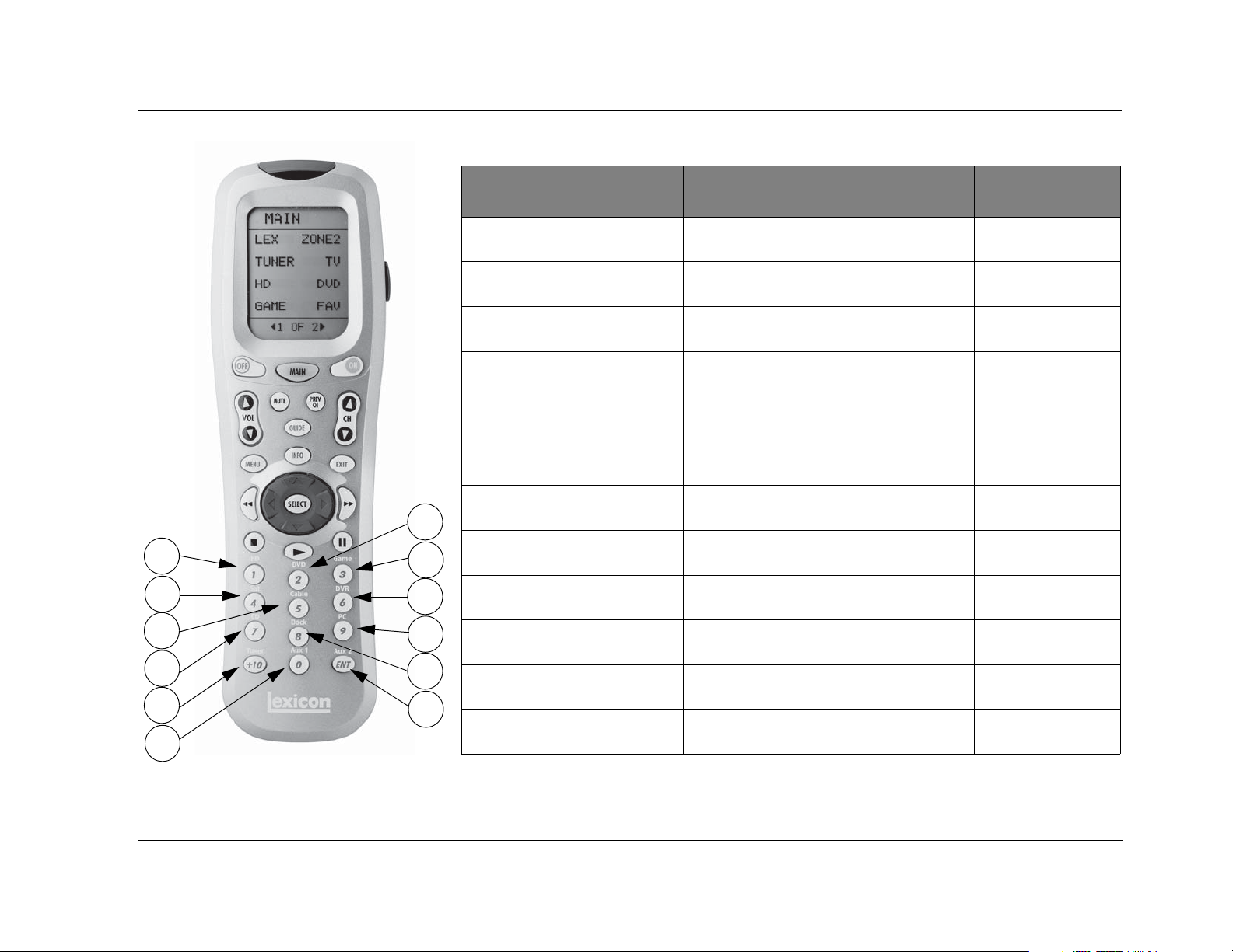
REMOTE CONTROL BUTTONS
1. Touch Screen (component and function buttons)
2. MAIN remote control touch screen menu
1
9
2
3. OFF
4. VOLUME (+/-)
5. MUTE
3
4
5
6
7
8
Note: The number call-outs on the figure above
correlate with the numbers listed to the right.
10
11
12
13
14
15
6. MENU
7. SELECT & Navigation (left, right, up, & down)
8. Number Keypad & ENT (Enter)
9. LIGHT (back light for the remote control)
10. ON
11. CHANNEL (+/-)
12. PREV CH (Previous Channel)
13. GUIDE & INFO
14. EXIT
15. Transport functions (PLAY , STOP , RW , PAUSE
for source components
Note: These are the names and functions for the universal remote control.
For the MV-5 specific remote control functions, refer to the Command
Matrix on the following page.
||, & FF )
2-10
Page 21

MV-5 Basic Operation
MENU OPTIONS
Selecting a menu option can open another menu within the menu
structure. For example, selecting SETUP from the MAIN MENU opens
the SETUP menu.
MAIN MENU
AUDIO CONTROLS
VIDEO STATUS
SETUP
SETUP
DISPLAY SETUP
SPEAKER/EQ SETUP
INPUT SETUP
SURROUND CONFIG
DOLBY CONFIG
MUTE LEVELS
POWER ON SETTINGS
MENU ITEM SELECTION
Use the remote control arrows to navigate the menu structure.
To select a menu item in an open menu:
1. Press the Menu or Select buttons to enter the Menu structure.
2. Navigate to the desired menu.
3. Press the remote control and arrows to highlight the
desired menu item.
4. When the desired menu item is highlighted, press the arrow
or SELECT button to select the highlighted item. If an option is
selected, another menu opens. When an adjustable parameter is
selected, the current selection will blink to indicate that it is
selected. Use the and arrows to scroll through the available
options for the selected parameter. When the desired parameter
option is highlighted, press the arrow on the remote control to
select the option.
REMOTE CONTROL LIGHT BUTTON
The remote control is fully back lit, making it very useful in low-light
conditions. Press the LIGHT button on the right side of the remote
to back light all of the buttons and the LCD touch screen. To turn
off the back light, press the LIGHT button again or wait. Ten
seconds after the last button is pressed, the back light will
automatically shut off.
COMMAND MATRIX
The command matrix table, starting on the next page, lists the
commands that each remote control button performs in each menu
setting.
Note: A brief description of each function is given in the table but refer to
the Table of Contents for additional information on each function. For
additional information on using and programming the remote control,
refer to Appendix C.
2-11
Page 22
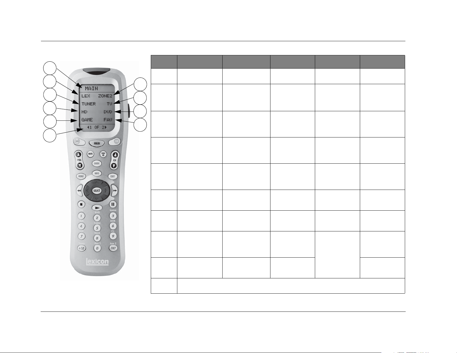
Basic Operation Lexicon
MAIN LEX PAGE1 LEX PAGE2 LEX PAGE3 LEX PAGE4
1
2
4
6
8
3
5
7
9
10
Note: The number call-outs on the figure above
correlate with the numbers in the adjoining table.
1
2
3
4
5
6
7
8
9
10
*The Menu Name is not a functional command. It is simply a label identifying which menu or sub-menu the touch screen currently
displays.
Menu Name MAIN*
LEX
Enters the Lexicon
MV-5 menu layer
ZONE2
Enters the Lexicon
MV-5 Zone 2 menu
layer
TUNER
(Does not affect the
MV-5)
TV
(Does not affect the
MV-5)
HD
(Does not affect the
MV-5)
DVD
Enters the Lexicon
RT-10/RT-20 menu
GAME
(Does not affect the
MV-5)
FAV
(Does not affect the
MV-5)
MENU PAGE - <ACTIVE PAGE> OF <TOTAL PAGES>
Tou ch or to scrolll between the menu pages
Menu Name - LEX Menu Name - LEX Menu Name - LEX
L7
Selects the Logic 7
listening mode family
STER
Selects the Stereo
listening mode family
DOLBY
Selects the Dolby
listening mode family
DTS
Selects the DTS
listening mode family
DSP
Selects the DSP
listening mode family
AUDIN
Selects either Digital
or Analog Audio.
TONE
Tog g l es the To ne
Control parameter
between ON & OFF.
ZOOM
(unused)
EQ
Toggles the Auto EQ
parameter between
ON & OFF.
PRE1
Sets the MV-5 to the
Autocal Preset 1
saved values
PRE2
Sets the MV-5 to the
Autocal Preset 2
saved values
PRE3
Sets the MV-5 to the
Autocal Preset 3
saved values
TREBLowers the Treble
parameter
TREB+
Raises the Treble
parameter
BASSLowers the Bass
parameter
BASS+
Raises the Bass
parameter
(iPod controls)
IPODiPod
IPOD+
iPod
CLIK
iPod wheel click,
counterclockwise
CLIK
iPod wheel click,
clockwise
MENU
iPod MENU button
SEL
iPod SELECT button
II
iPod Play/Pause
button
Menu Name - LEX
(PC controls)
PCPC
PC+
PC
PCII
PC Play/Pause
(unused)
(unused)
(unused)
(unused)
(unused)
2-12
Page 23
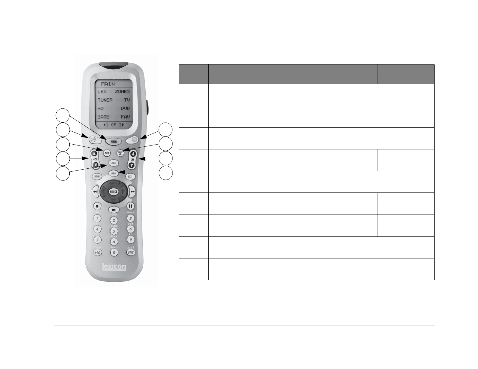
MV-5 Basic Operation
11
12
14
16
18
13
15
17
19
11
12
13
14
15
16
17
18
MAIN*
MAIN*
Returns to the Main layer of the remote control
OFF Puts the MV-5 Processor into Standby
ON Turns on the MV-5 Processor from Standby
MUTE Mutes the Main Zone Volume Mutes the Zone 2
PREV CH (unused)
VOL or VOL Main Zone
VOL or VOL
CH or CH Main Zone
MODE or MODE
GUIDE Steps through the VIDEO STATUS menu
LEX
PAGE1-4
ZONE 2
PAGE 1-3
Volume
Zone 2
VOL or VOL
(unused)
Note: The number call-outs on the figure above
correlate with the numbers in the adjoining table.
19
*The MAIN menu level does NOT control the MV-5. The remote control touch screen heading must read “LEX” or “ZONE 2”
in order to control the MV-5 Processor.
INFO Steps through the AUDIO STATUS menu
2-13
Page 24
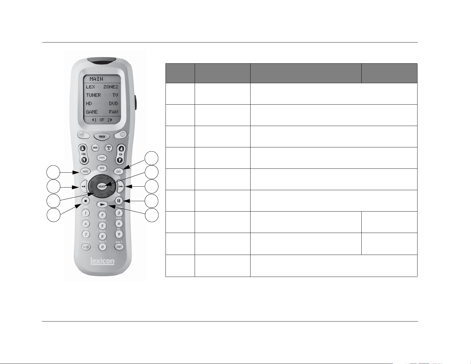
Basic Operation Lexicon
20
22
24
26
21
23
25
27
28
20
21
22
23
24
25
26
27
MAIN*
MENU Enters OSD menu
EXIT Exits OSD menu
REWIND
SELECT Enters OSD menu,
Arrows
FAST FORWARD
STOP
||
PAU SE
(unused)
While in OSD menu, selects menu items
Used for OSD menu navigation
If not in the OSD menu structure, no function.
(unused)
Main Zone OFF Zone 2 OFF
Changes Front panel display illumination (unused)
LEX
PAGE1-4
ZONE 2
PAGE 1-3
Note: The number call-outs on the figure above
correlate with the numbers in the adjoining table.
2-14
28
*The MAIN menu level does NOT control the MV-5. The remote control touch screen heading must read “LEX” or “ZONE 2”
in order to control the MV-5 Processor.
PLAY
(unused)
Page 25
MV-5 Basic Operation
29
32
33
35
38
39
Note: The number call-outs on the figure above
correlate with the numbers in the adjoining table.
30
31
34
37
36
40
MAIN*
29
30
31
32
33
34
35
36
37
38
39
40
*The MAIN menu level does NOT control the MV-5. The remote control touch screen heading must read “LEX” or “ZONE 2”
in order to control the MV-5 Processor.
1Main Zone
HD input
2Main Zone
DVD input
3Main Zone
Game input
4Main Zone
Sat input
5Main Zone
Cable input
6Main Zone
DVR input
7Main Zone
CD input
8Main Zone
Dock input
9Main Zone
PC input
+10 Main Zone
Tun e r input
0Main Zone
Aux 1 input
ENT
Enter
Main Zone
Aux 2 input
LEX
PAGE1-4
ZONE 2
PAGE 1-3
Zone 2
HD input
Zone 2
DVD input
Zone 2
Game input
Zone 2
Sat input
Zone 2
Cable input
Zone 2
DVR input
Zone 2
CD input
Zone 2
Dock input
Zone 2
PC input
Zone 2
Tun e r input
Zone 2
Aux 1 input
Zone 2
Aux 2 input
2-15
Page 26

Basic Operation Lexicon
2-16
Page 27

3
Setup
Setup ......................................................................................... 3-2
Display Setup ............................................................................. 3-3
Speaker/EQ Setup ...................................................................... 3-5
Manual ..................................................................................................... 3-6
Semi Autocal............................................................................................. 3-6
Full Autocal ............................................................................................... 3-6
Manual Speaker Setup................................................................ 3-8
Speakers Menu.......................................................................................... 3-9
Speaker Distances Menu ......................................................................... 3-10
Output Levels Menu................................................................................3-11
Input Setup .............................................................................. 3-13
Advanced Video ...................................................................................... 3-19
Listening Modes....................................................................... 3-22
Selecting a Listening Mode .....................................................................3-22
DTS + Dolby Listening Modes ................................................................. 3-22
Available Listening Modes .......................................................................3-23
Listening Mode Descriptions ................................................................... 3-26
5.1-channel & 7.1-channel Direct Inputs................................................. 3-28
DTS & Dolby Status Displays...................................................................3-28
Surround Configuration ........................................................... 3-29
Dolby Configuration................................................................. 3-31
Mute Levels.............................................................................. 3-32
Power On Settings ................................................................... 3-32
Page 28
Setup Lexicon
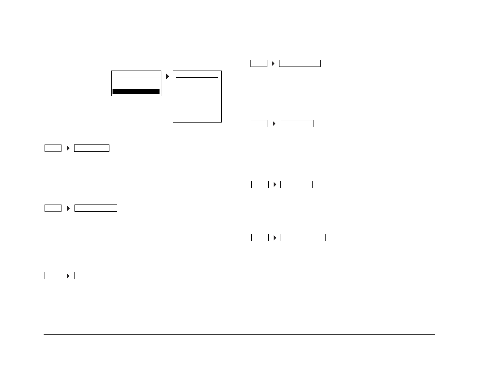
SETUP
Selecting SETUP from
the MAIN MENU
opens the SETUP
menu.
DISPLAY SETUP
SETUP DISPLAY SETUP
Opens the DISPLAY SETUP menu, which is used to customize the
OSD and front panel display, as well as other display-related
parameters. See the “Display Setup” section on the following page
for more information.
SPEAKER/EQ SETUP
SPEAKER/EQ SETUPSETUP
Opens the SPEAKER/EQ SETUP menu, which is used to configure the
Main Zone and Zone 2 audio output connectors for the desired
speaker setup, set speaker cross-overs, and calibrate distances and
output levels. See the “Speaker/EQ Setup” section found later in this
chapter for more information.
INPUT SETUP
INPUT SETUPSETUP
MAIN MENU
AUDIO CONTROLS
VIDEO STATUS
SETUP
SETUP
DISPLAY SETUP
SPEAKER/EQ SETUP
INPUT SETUP
SURROUND CONFIG
DOLBY CONFIG
MUTE LEVELS
POWER ON SETTINGS
SURROUND CONFIGURATION
SURROUND CONFIGSETUP
Opens the SURROUND CONFIG menu, which is used to customize
the listening modes that are available for the currently selected input.
See the “Surround Configuration” section found later in this chapter
for more information.
DOLBY CONFIGURATION
DOLBY CONFIGSETUP
Opens the DOLBY CONFIG menu, which is used to customize the Dolby
listening modes to your personal preferences. See the“Dolby
Configuration” section found later in this chapter for more
information.
MUTE LEVELS
MUTE LEVELSSETUP
Opens the MUTE LEVELS menu, which is used to set the mute level
controls. See the “Mute Levels” section found later in this chapter for
more information.
POWER ON SETTINGS
SETUP
Opens the POWER ON SETTINGS menu, which is used to configure
the power on volume level and the Dock auto power feature. See
the “Power On Settings” section found later in this chapter for more
information.
POWER ON SETTINGS
Opens the INPUT SETUP menu, which is used to change input
names, assign audio and video input connectors, select preferred
listening modes and configure Main Zone and Zone 2 settings. See
the “Input Setup” section found later in this chapter for more
information.
3-2
Note: When a source is active, changing some audio or video parameters
may cause the Main Zone audio to briefly mute the incoming source. If
Zone 2 is set to DOWN MIX, the Zone 2 audio will also briefly mute.
Page 29
MV-5 Setup
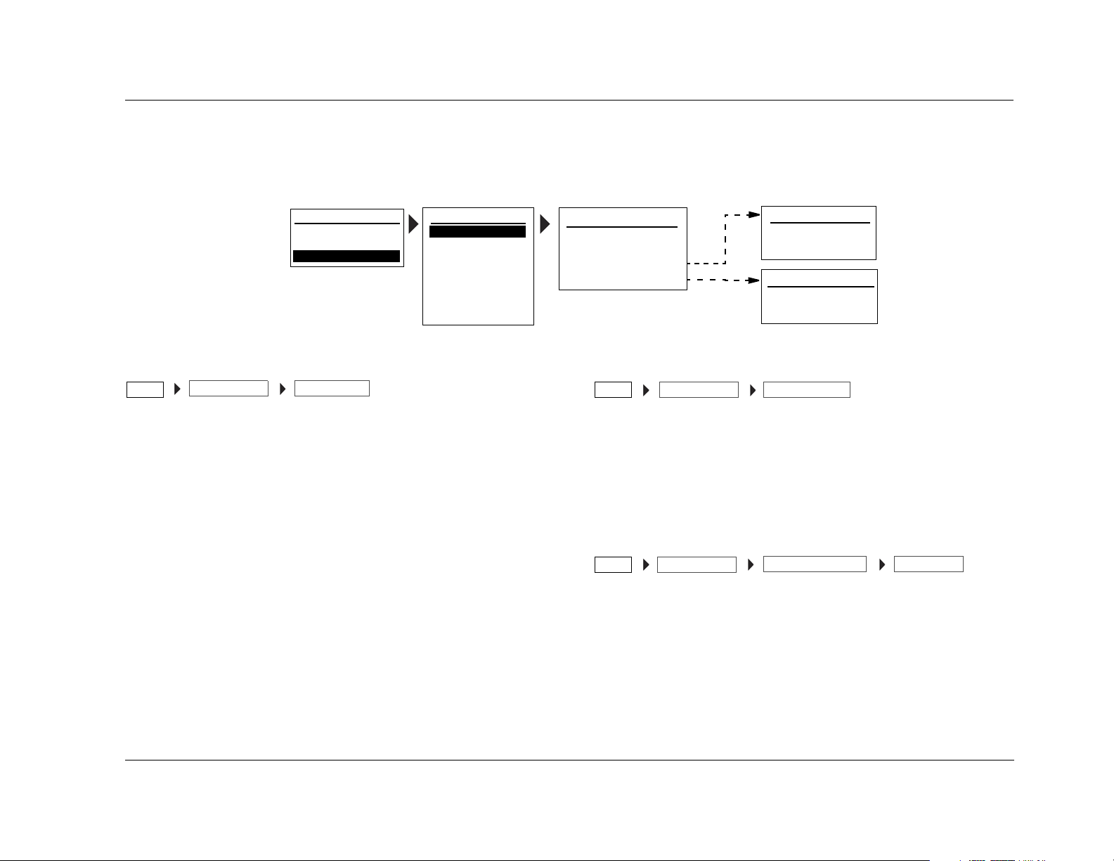
DISPLAY SETUP
Selecting the SETUP menu DISPLAY SETUP option opens the DISPLAY SETUP menu, which is used to customize the OSD and front panel display and
setup other display-related features.
MAIN MENU
AUDIO CONTROLS
VIDEO CONTROLS
SETUP
SETUP
DISPLAY SETUP
SPEAKER/EQ SETUP
INPUT SETUP
SURROUND CONFIG
DOLBY CONFIG
MUTE LEVELS
POWER ON SETTINGS
CONNECTION ANALOG, HDMI/DVI
SETUP
DISPLAY SETUP
Selects the CONNECTION parameter, which identifies the active
video output connectors on the MV-5 rear panel. The following list of
conditions identify the behavior of this parameter.
• If ANALOG is selected, only the analog video connectors are
available and will output the video signal.
• If HDMI/DVI is selected, both the analog and HDMI video
connectors are available and will output the video signal.
• If the video input is set to HDMI and the CONNECTION
parameter is set to ANALOG, then no video is output.
• If the HDMI video input is copy-protected (HDCP), no video is
output on the analog output connectors. This is a requirement
of HDCP and not a limitation of the MV-5 Processor.
CONNECTION
DISPLAY SETUP
CONNECTION: HDMI/DVI
HDMI AUDIO OUT: NO
ON-SCREEN DISPLAY
FRONT PANEL DISPLAY
ON-SCREEN DISPLAY
2-LINE OSD: 3s
MENU TIME OUT: 30s
FRONT PANEL DISPLAY
BRIGHTNESS: FULL
TIME OUT: NONE
HDMI AUDIO OUT YES, NO
DISPLAY SETUPSETUP
Selects the HDMI AUDIO OUT parameter, which identifies if audio is
sent on the HDMI output. If the HDMI AUDIO OUT parameter is set
to YES, then a two-channel DOWN MIX of the source audio is sent
over the HDMI connection at the maximum bit rate of the display’s
audio system. This audio stream is in addition to the normal audio
outputs. If the parameter is set to NO, this audio is not sent.
HDMI AUDIO OUT
2-LINE OSD OFF, 3, 4, 5, 6 SECONDS
DISPLAY SETUPSETUP
Selects the 2-LINE OSD parameter from the On-Screen Display (OSD)
menu. The 2-Line OSD parameter identifies the length of time that
the 2-line OSD is displayed and can be set to display from three to six
seconds in one-second increments. If OFF is selected, then the 2-line
OSD is not displayed.
ON-SCREEN DISPLAY 2-LINE OSD
Note: If OFF is selected, the menu screens are still displayed. This
parameter only affects the 2-line OSD display, which is identical to the
front panel 2-line display.
3-3
Page 30
Setup Lexicon
MENU TIME OUT NONE, 30, 40, 50, 60 SECONDS
DISPLAY SETUPSETUP
Selects the MENU TIME OUT parameter from the On-Screen Display
(OSD) menu. This parameter identifies the length of time before the
OSD menu times out and can be set from 30 to 60 seconds in
ten-second increments. If NONE is selected, then the OSD will not
turn off automatically.
ON-SCREEN DISPLAY MENU TIME OUT
CAUTION!
The NONE selection should only be used with caution. If
the system includes a plasma display, or other display
types sensitive to image burn-in, and the OSD Menu Time
Out parameter is set to NONE, the OSD menu image can be
burned into the monitor display.
BRIGHTNESS FULL, HALF, OFF
SETUP
DISPLAY SETUP
Selects the BRIGHTNESS parameter from the Front Panel Display
menu, which selects the brightness of the 2-line front panel display.
The parameter can be set to FULL, HALF, or OFF. If set to OFF, then
the front panel display is off.
FRONT PANEL DISPLAY
BRIGHTNESS
TIME OUT NONE, 1 TO 10 SECONDS
SETUP
DISPLAY SETUP
Selects the TIME OUT parameter from the Front Panel Display menu.
This parameter identifies the length of time before the front panel
2-line display times out. The parameter can be set from 1 to 10
seconds in one-second increments. If NONE is selected, then the
2-line front panel display is always on when the MV-5 is on.
FRONT PANEL DISPLAY TIME OUT
On the remote control, this parameter is controlled by the
|| (Pause)
button while in the touch screen “LEX” menu layer.
Note: When the MV-5 is powered off or put into Standby mode, any
changes to the BRIGHTNESS parameter are not saved. So when the MV-5
is powered on or taken out of Standby mode again, the BRIGHTNESS
parameter will be set to FULL.
3-4
Page 31

MV-5 Setup
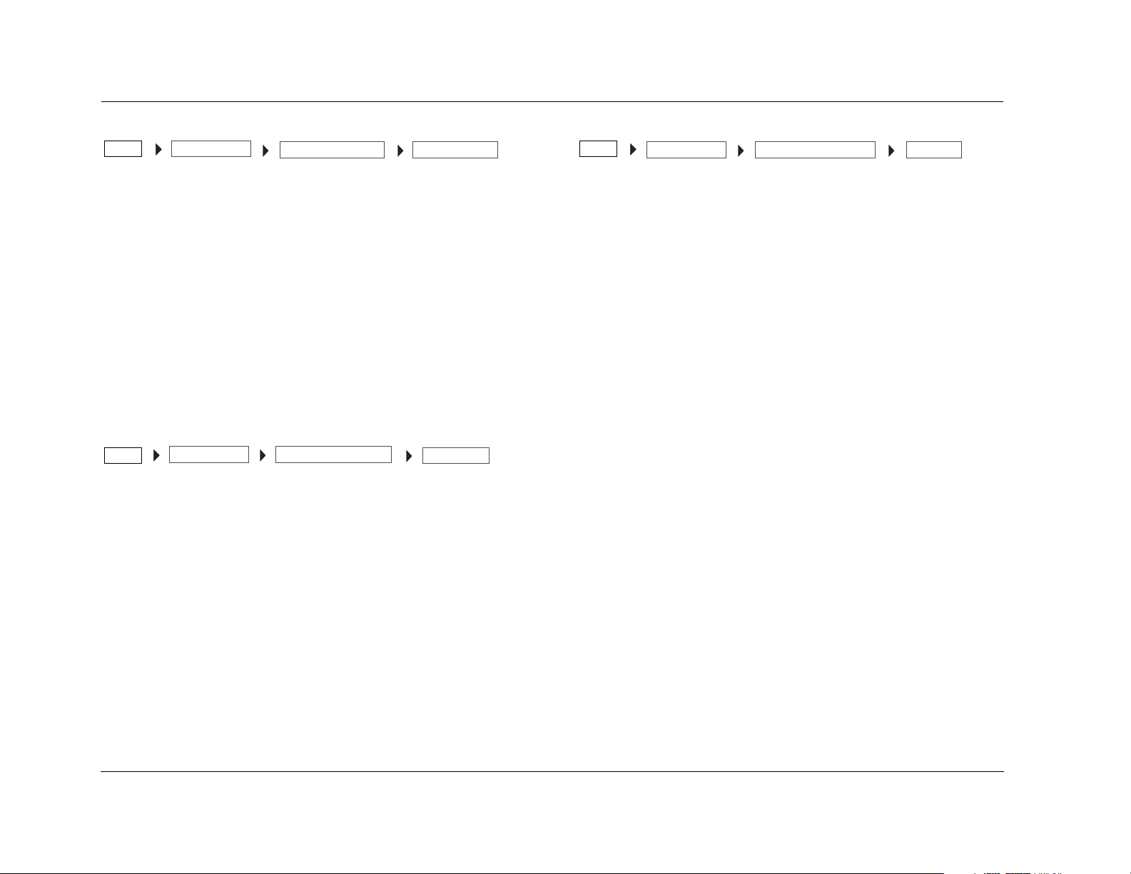
SPEAKER/EQ SETUP
Select the SPEAKER/EQ SETUP menu to configure the Main Zone audio output connectors for the desired speaker setup. The Main Zone includes eight
audio output connectors labeled Front L/R, Center, Subwoofer, Side L/R and Rear L/R.
MAIN MENU
AUDIO CONTROLS
VIDEO STATUS
SETUP
SETUP
DISPLAY SETUP
SPEAKER/EQ SETUP
INPUT SETUP
SURROUND CONFIG
DOLBY CONFIG
MUTE LEVELS
POWER ON SETTINGS
SPEAKER/EQ SETUP
MANUAL
SEMI AUTOCAL
FULL AUTOCAL
MANUAL
SPEAKERS
SPEAKER DISTANCES
OUTPUT LEVELS
PERFORMS SEMI-AUTOMATIC
CALIBRATION
PERFORMS FULL AUTOMATIC
CALIBRATION
SPEAKER DISTANCES 1
AUTO SETTINGS: OFF
UNITS: FEET
FRONT LEFT: 0.0 ft
CENTER: 0.0 ft
FRONT RIGHT: 0.0 ft
SIDE RIGHT: 0.0 ft
REAR RIGHT: 0.0 ft
REAR LEFT: 0.0 ft
OUTPUT LEVELS 1
AUTO SETTINGS: OFF
INPUT: ALL
TEST TONE: OFF
FRONT LEFT: 0dB
CENTER: 0dB
FRONT RIGHT: 0dB
SIDE RIGHT: 0dB
REAR RIGHT: 0dB
SPEAKERS
AUTO SETTINGS: OFF
FRONT L/R: 80Hz
CENTER: 80Hz
SIDE L/R: 80Hz
REAR/Z2 L/R: 80Hz
SUB/LFE LPF: 80Hz
SUBWOOFERS: 1
SUB HPF: 20Hz
SUB MODE: NORMAL
SPEAKER DISTANCES 2
SIDE LEFT: 0.0ft
SUBWOOFERS: 0.0 ft
OUTPUT LEVELS 2
REAR LEFT: 0dB
SIDE LEFT: 0dB
SUBWOOFER1: 0dB
SUBWOOFER2: 0dB
3-5
Page 32

Setup Lexicon
MANUAL
SETUP
Opens the MANUAL speaker setup menu, which allows the manual
selection of the speaker distances, cross-over points, and output
levels. See the next section, “Manual Speaker Set-Up”, for more
details.
SPEAKER/EQ SETUP MANUAL
SEMI AUTOCAL
SETUP
Selects the SEMI AUTOCAL procedure, which automatically sets the
speaker distances and output levels, as well as performing system
equalization adjustments. The cross-over points for each speaker
must be manually set before this procedure can be run. See the next
section, “Manual Speaker Set-Up”, for more information on how to
set the cross-over points.
Performing the Semi Autocal Procedure:
In order to perform this test, the following initial setup is required:
• All of the speakers are connected to the MV-5 and positioned in
the listening space.
• The cross-over points for each speaker are set through the
MANUAL setup menu. See the following section, “Manual
Speaker Setup”, for information on how to manually set the
cross-over points.
• A monitor is connected to the MV-5 for viewing the OSD
during the procedure.
• The microphone, included with the MV-5, must be connected
to the rear panel Microphone input connector and positioned
in the primary listening position.
For best results, install the microphone onto the accompanying rod by
threading the two parts together and hold or place it in the primary
listening position. Use a microphone stand or tripod if necessary.
SPEAKER/EQ SETUP SEMII AUTOCAL
The Semi Autocal procedure is performed in the same manner as the
Full Autocal procedure. Refer to the “Performing the Full Autocal
Procedure” for more details.
CAUTION!
DO NOT place the microphone too close to the speakers
during the autocal procedure. If the microphone is within
one foot of the speaker, the test tones that are output
during the autocal procedure could cause a feedback loop
which may damage the speaker. Harman Specialty Group
assumes no responsibility for speaker damage.
FULL AUTOCAL
SETUP
Selects the FULL AUTOCAL procedure, which automatically sets the
speaker distances, cross-over points, and output levels, as well as
performing system equalization adjustments.
Note: The Full or Semi Autocal settings that are saved to the Preset
locations include the system equalization adjustment values. However,
even if the Auto EQ setting is active, the autocal settings for the system EQ
do NOT apply to certain high bit-rate incoming data streams, such as 176
kHz and 192 kHz PCM.
Performing the AUTOCAL Procedure:
Before beginning the AUTOCAL procedure, set the MV-5 to an input
that does not have a currently active source. There should NOT be
an active audio track playing when the AUTOCAL procedure
is started.
In order to perform this test, the following initial setup is required:
• All of the speakers are connected to the MV-5 and positioned in
the listening space.
SPEAKER/EQ SETUP FULL AUTOCAL
3-6
Page 33

MV-5 Setup
• A monitor is connected to the MV-5 for viewing the OSD
during the procedure.
• The microphone, included with the MV-5, must be connected
to the rear panel Microphone input connector and positioned
in the primary listening position.
Note: For best results, install the microphone onto the accompanying
rod by threading the two parts together and hold or place it in the
primary listening position. Use a microphone stand or tripod if
necessary.
CAUTION!
DO NOT place the microphone too close to the speakers
during the autocal procedure. If the microphone is within
one foot of the speaker, the test tones that are output
during the autocal procedure could cause a feedback loop
which may damage the speaker. Harman Specialty Group
assumes no responsibility for speaker damage.
The Full Autocal procedure is comprised of three parts, the Far Field
Test, the Near Field Test, and the Subwoofer Test. Each part provides
directions on the OSD at the start of the test, for volume level and
microphone positioning, and each test sends test tones to the
speakers.
The Far Field test sets the speaker distances, cross-over points, and
output levels. The microphone is stationed in the center of the
preferred listening area and a test tone is sent to each speaker.
Note: If the Far Field test is skipped, the Near Field test must also be
skipped.
The Near Field test adjusts the MV-5, performing system equalization
to compensate for speaker performance and placement. The
procedure seeks to give the system a consistent tonal balance
between the front left, front right, center, side left, side right, rear left,
and rear right speakers, if applicable. The test calibrates each speaker
separately, and the user individually selects each speaker to calibrate.
The microphone should be held within two feet of the speaker baffle
as a test tone is sent to the speaker.
The Subwoofer test is done in two parts. The user is instructed to
hold the microphone to the left of the primary listening position and
then to the right of the primary listening position. Two test tones are
sent out to all connected subwoofers during each of the two test
phases. Two tones are sent to ensure that subwoofers with auto
power settings are active during the procedure.
Note: If there are no subwoofers in the system, then this test will not pass
and must be skipped.
Note: Before activating the calibration, ensure that the MV-5 is NOT
muted. If Mute is active, then the test tone calibrations will not be
accurate.
For the Far Field test, the test tones sent to each speaker follow a
specific order. The order of testing is Front Left, Front Right, Center,
Side Left, Side Right, Rear Left, and Rear Right.
Note: The test tones may be loud. Be prepared before starting the Full or
Semi Autocal procedures.
For optimum results, all noise generators in the room should be
removed before performing the full or semi autocal procedure.
However, air conditioners and similar steady-state background noise
should have minimum impact on the test and can be left on.
When the procedure is complete, the user will be prompted to save
the settings. These settings can be saved in one of three Preset
locations. See Section 4: Audio Controls & Video Status for more
information on the Preset locations.
Note: When calibration is complete, the volume level is set to a relatively
high level. Before playing an audio track, be sure to turn the volume
down to avoid potentially offensive or damaging volume levels.
3-7
Page 34

Setup Lexicon
MANUAL SPEAKER SETUP
Selecting the SETUP menu SPEAKER/EQ SETUP menu MANUAL option opens the MANUAL menu, which is used to manually set the speaker
distances, cross-over points, and output levels.
SPEAKER/EQ SETUPSETUP
MANUAL
SPEAKERS
SPEAKER DISTANCES
OUTPUT LEVELS
SPEAKER DISTANCES 1
AUTO SETTINGS: OFF
UNITS: FEET
FRONT LEFT: 0.0 ft
CENTER: 0.0 ft
FRONT RIGHT: 0.0 ft
SIDE RIGHT: 0.0 ft
REAR RIGHT: 0.0 ft
REAR LEFT: 0.0 ft
OUTPUT LEVELS 1
AUTO SETTINGS: OFF
INPUT: ALL
TEST TONE: AUTO
FRONT LEFT: 0dB
CENTER: 0dB
FRONT RIGHT: 0dB
SIDE RIGHT: 0dB
REAR RIGHT: 0dB
AUTO SETTINGS OFF, ON
SETUP
SPEAKER/EQ SETUP MANUAL
Loads the values from the active preset into the speaker cross-over
points, distances, or output level parameters. The Speakers
(cross-over points), Speaker Distances, and Output Levels menus all
have an Auto Settings parameter. All three are the same parameter,
but each affects the individual sub-menus separately and
independently of each other.
AUTO SETTINGS
SPEAKERS
SPEAKER DISTANCES 2
SIDE LEFT: 0.0ft
SUBWOOFERS: 0.0 ft
OUTPUT LEVELS 2
REAR LEFT: 0dB
SIDE LEFT: 0dB
SUBWOOFER1: 0dB
SUBWOOFER2: 0dB
AUTO SETTINGS: OFF
FRONT L/R: 80Hz
CENTER: 80Hz
SIDE L/R: 80Hz
REAR/Z2 L/R: 80Hz
SUB/LFE LPF: 80Hz
SUBWOOFERS: 1
SUB HPF: 20Hz
SUB MODE: NORMAL
If the Auto Settings parameter is set to ON, the parameters in that
menu cannot be manually changed until the Auto Settings
parameter is set to OFF.
Note: Any manual settings will be lost if the active preset settings are
loaded; if Auto Settings is set to ON in the Speakers, Speaker Distances, or
Output Levels menus, then previous parameter values will be overwritten.
3-8
Page 35

MV-5 Setup
SPEAKERS MENU
SETUP
Selecting the MANUAL SETUP menu SPEAKERS option opens the
SPEAKERS menu, which assigns independent cross-over points for
each Main Zone audio output connector. Front cross-over selections
affect the Sub Mode parameter options.
Manual Speaker Setup Considerations:
• Select the cross-over point closest to the -3dB low frequency
rating of the associated speakers. For example, set the FRONT
L/R parameter to the cross-over point closest to the -3dB
low-frequency rating of the front speakers.
• Select the subwoofer cross-over point equal to the lowest crossover point of any of the other speakers.
Manual Subwoofer Speaker Setup Considerations:
All low frequencies below the speaker’s cross-over point are
redirected from the speaker to the subwoofer(s). If the cross-over
point is FULL, low-frequency signals, excluding LFE information, are
not redirected to the subwoofer.
Low frequencies between the Subwoofer and Front L/R speaker
channels can be duplicated. However, making this selection can
result in excessive bass. Refer to the “Sub Mode” description found
later in this chapter for more information.
Note: The Semi Autocal and Full Autocal procedures leave the Subwoofer
distance value at a default of 0.0 feet. Refer to the “Speaker Distances”
section found later in this chapter to manually set the correct Speaker
Distance for the subwoofers.
SPEAKER/EQ SETUP MANUAL
SPEAKERS
FRONT L/R FULL, 40 to 120HZ
include FULL, 120 Hz, 100 Hz, and 80 Hz to 40 Hz in 10 Hz
increments.
Select FULL to send a full-range signal to the front speakers.
Otherwise, select the cross-over point closest to the -3dB
low-frequency rating of the front speakers.
CENTER FULL, 40 to 120HZ, NONE
Allows the manual selection of a cross-over point for the Main Zone
audio output connector labeled Center. Available selections include
NONE, FULL, 120 Hz, 100 Hz, and 80 Hz to 40 Hz in 10 Hz
increments.
• Select FULL to send a full-range signal to the center speaker.
Otherwise, select the cross-over point closest to the -3dB
low-frequency rating of the center speaker.
• When the speaker setup does not include a center speaker, select
NONE because some listening modes are not intended to be used
without a center channel.
SIDE L/R FULL, 40 to 120Hz, NONE
Allows the manual selection of a cross-over point for the Main Zone
audio output connectors labeled Side L/R. Available selections
include NONE, FULL, 120 Hz, 100 Hz, and 80 Hz to 40 Hz in 10 Hz
increments.
• Select FULL to send a full-range signal to the Side L/R speakers.
Otherwise, select the cross-over point closest to the -3dB
low-frequency rating of the Side L/R speakers.
• When the speaker setup does not include side speakers, select
NONE to redirect side channel signals to the Front L/R output
connectors. If the Rear L/R parameter is also set to NONE, the
MV-5 will redirect surround channel signals to the Front L/R
output connectors.
Allows the manual selection of a cross-over point for the Main Zone
audio output connectors labeled Front L/R. Available selections
3-9
Page 36

Setup Lexicon
REAR L/R FULL, 40 to 120Hz, NONE
Allows the manual selection of a cross-over point for the Main Zone
audio output connectors labeled REAR/Z2 L/R. Available selections
include NONE, FULL, 120 Hz, 100 Hz, and 80 Hz to 40 Hz in 10 Hz
increments.
• Select FULL to send a full-range signal to the Rear L/R speakers.
Otherwise, select the cross-over point closest to the -3dB
low-frequency rating of the Rear L/R speakers.
• When the speaker setup does not include rear speakers, select
NONE to redirect rear channel signals to the Side L/R output
connectors. If the Side L/R parameter is also set to NONE, the
MV-5 will redirect surround channel signals to the Front L/R
output connectors.
Note: When the Rear L/R parameter is set to NONE, Dolby Digital PLIIx
modes and DTS(-ES) decoding are not available.
SUB/LFE LPF (LOW-PASS FILTER) 40 to 120 Hz
Identifies the cross-over frequency setting below which sounds that
may be available from an LFE track are sent to the subwoofer.
Available selections are 120 Hz, 100 Hz, and 80 Hz to 40 Hz in 10 Hz
increments.
SUBWOOFERS 0, 1, 2
SUB MODE NORMAL, LFE+FL/FR, LFE ONLY
Selects options that are available to control bass redirection. Available
settings are NORMAL, LFE+FL/FR and LFE ONLY.
NORMAL is the default setting when Front L/R cross-overs are set to
any value other than FULL, and it is not user adjustable. In this mode,
all frequencies below the cross-over point of any main speakers
(Front, Center, Side, or Rear) are sent to the subwoofer. In addition, if
the incoming audio stream contains an LFE (.1) channel, all
frequencies in that channel which are below the SUB/LFE LPF crossover point are also sent to the subwoofer(s).
When the Front L/R cross-over is set to FULL, the user has the choice
of LFE+FL/FR or LFE ONLY.
The default setting, LFE+FL/FR, steers all Front L/R sounds below a
fixed cross-over point of 80Hz to BOTH the subwoofer(s) and the
Front L/R speakers. In addition, it redirects all frequencies below the
cross-over points of the Center, Side, and Rear speakers to the
subwoofer(s). Finally, if the incoming audio stream contains an LFE
(.1) channel, all frequencies in that channel which are below the
SUB/LFE LPF cross-over point are also sent to the subwoofer(s).
The LFE ONLY setting does not send any sound to the subwoofer(s)
other than the LFE (.1) channel, if available.
Selects the number of subwoofers in the system. Available selections
are 0, 1, or 2. The 0 selection is only available if the Front Left &
Right speakers are set to FULL.
SUB HPF (HIGH-PASS FILTER) 15, 20, 30, 38 Hz
Identifies the cross-over frequency setting above which sounds are
sent to the subwoofer. As a general rule of thumb, the larger the
subwoofer driver, the lower the frequency should be of the Sub HPF
parameter. The available selections are 15, 20, 30, and 38 Hz.
3-10
SPEAKER DISTANCES MENU
SETUP
Selecting the MANUAL SETUP menu SPEAKER DISTANCES option
opens the SPEAKER DISTANCES menu, which allows the user to
manually set the distances for each speaker. The adjustable range is
0.0 ft (0.0 m) to 30.0 ft (9.00 m) at 0.2 ft (0.06 m) increments.
SPEAKER/EQ SETUP MANUAL
SPEAKER DISTANCES
Page 37

MV-5 Setup
The distances for each speaker - Front Left, Center, Front Right, Side
Right, Rear Right, Rear Left, Side Left, and Subwoofers - can be set
individually.
Note: When the speaker distance for the Front Left speaker is adjusted
above 20.0 feet from the shortest speaker distance, all speaker distances
will move in conjunction from the 20.2-feet parameter point. When the
Front Left speaker is adjusted to 20.2 feet, all other speaker distances that
are set to 0 feet will now move to 0.2 feet. If the Front Left speaker
distance is increased to 22 feet, all other speaker distances will move to 2
feet (unless they are set to a higher value). If the Front Left speaker
distance is then decreased, all other speaker distances will not change.
UNITS FEET, METERS
Identifies the units of measure of the speaker distances. FEET and
METERS are the available selections.
OUTPUT LEVELS MENU
SETUP
Selecting the MANUAL SETUP menu OUTPUT LEVELS option opens
the OUTPUT LEVELS menu, which allows the user to manually set the
output levels for each speaker. The output levels can be set
independently for each input. The adjustable range is -15 dB to +5 dB
in 1 dB increments.
The output levels for each speaker - Front Left, Center, Front Right,
Side Right, Rear Right, Rear Left, Side Left, Subwoofer1, and
Subwoofer2 - can be set individually.
Note: The speaker output level settings may affect the maximum volume
level of the MV-5 Processor. The maximum volume level is +10 dB minus
the maximum output level setting of any speaker. Thus, if your Front L/R
output levels are set to +3.0 dB, then the maxium allowable volume level
is +10 dB minus 3 dB, or +7.0 dB.
SPEAKER/EQ SETUP MANUAL
OUTPUT LEVELS
INPUT
Identifies the input that the currently displayed output levels will be
applied to. The Input selection toggles between the currently
selected front panel input and ALL. If the front panel input is selected,
then only that input’s output levels are adjusted.
Note: To set a specific input’s output levels, the input front panel button
must be selected before the Input selection in the Output Levels menu is
available for that specific input.
The ALL selection functions as a virtual input – it holds values that can
be assigned to all inputs. Each input can override the ALL value with
its own custom settings. To assign the ALL input, it must be selected
individually for each front panel input selection.
Note: If the input is set to ALL and the auto settings are turned to ON,
then ALL takes the preset values for its settings. The Auto Settings, if set to
ON, apply to whatever INPUT is currenly selected.
TEST TONE OFF, AUTO, MANUAL
Provides a noise signal to each speaker through either the AUTO or
MANUAL setting. AUTO sends a rotating noise signal to each
speaker, in the order listed in the menu. If set to AUTO, the test tone
moves in a clockwise order around the speakers, starting from the
front left. MANUAL sends the pink noise signal only to the speaker
selected by the user. The OFF selection turns off the noise signal. Any
active input source is muted while the Test Tone parameter is active
and until the Test Tone parameter is set to OFF.
The available test tones are dependent upon the current listening
mode. For example, if a 5.1 channel listening mode is active, then
the rear speakers are not accessible to the Test Tone parameter.
Note: Before activating the test tones, ensure that the MV-5 is NOT
muted. If Mute is active, then the test tone calibrations will not be
accurate.
3-11
Page 38

Setup Lexicon
To activate the Test Tone:
1. Press the Menu or Select button to enter the Menu structure.
2. Select Setup from the Main menu.
3. Select Speaker/EQ Setup.
4. Select Manual.
5. Select Output Levels.
6. Press the remote control and arrows to highlight the Test
Tone paramet e r.
7. Press the remote control SELECT or arrow button to select
the Test Tone parameter.
8. Press the remote control arrow to select manual test tones.
The Test Tone parameter displays MANUAL and the highlighted
parameter is now Front Left. You should hear the test tone in
the Front Left speaker.
9. Press the remote control arrow to select automatic test
to ne s. T h e Te s t Ton e p a r a meter displays AUTO and the
highlighted parameter is now Front Left. You should hear the
test tone in the Front Left speaker, then in the Center speaker,
and so on through the list. After the last speaker, the test tone
will return to the Front Left speaker and continue down the list
again.
10. To stop the Test Tone, use the remote control and arrows
to highlight the Test Tone parameter. The parameter will
change to OFF. The test tone can no longer be heard through
any of the speakers.
3-12
Page 39

MV-5 Setup
INPUT SETUP
Selecting the SETUP menu INPUT SETUP option opens the INPUT SETUP menu, a two-screen menu which sets up the input type and name, the
digital and analog inputs for both audio and video, the listening mode, and other advanced input settings.
MAIN MENU
AUDIO CONTROLS
VIDEO STATUS
SETUP
SETUP
DISPLAY SETUP
SPEAKER/EQ SETUP
INPUT SETUP
SURROUND CONFIG
DOLBY CONFIG
MUTE LEVELS
POWER ON SETTINGS
INPUT SETUP 1
INPUT: HD
NAME: ________
VIDEO IN: HDMI 1
V-PROCESS: FAROUDJA
VIDEO OUT: AUTO
DIG AUDIO: HDMI 1
ANLG AUDIO: NONE
DIG/ANLG AUTO: ON
INPUT
INPUT SETUPSETUP
Selects between the twelve different inputs available. The input
selected in this parameter identifies the input that is currently being
setup or modified. Inputs can be scrolled through and modified
without leaving the input setup menu. However, most input setup
changes do not take affect until after the OSD menu is exited.
Note: Selecting a different input in the input setup menu will also change
the front panel input selection to match. For example, if the Tuner input is
selected on the front panel and you change the Input parameter to HD,
the front panel HD input is also selected.
Most of the inputs are interchangeable, with the exception of the
Dock and PC inputs. These two inputs are “hard-wired” and do not
allow for user selection of the Audio In parameters. For more information on these two inputs, refer to Section 5: PC & Dock Controls.
INPUT
INPUT SETUP 2
MODE FAMILY: STEREO
MODE: 2-CHANNEL
DEFAULT SUR: USE LAST
A/D SAMPLE RATE: 48kHz
A/V SYNC DELAY: 0 ms
ADVANCED VIDEO
TRIGGER 2: ON
ZONE-2 OUT: ANALOG
ADVANCED VIDEO 1
INPUT TYPE: VCR
SHARPNESS: 32
NOISE REDUCTION: ON
X-COLOR SUPPRESS: ON
DCDi INTERPOL: ON
FILM DETECTION: ON
FILM EDIT DETECT: ON
ADVANCED VIDEO 2
FLESHTONE NR: ON
COMPNT ENHANCE: ON
BRIGHTNESS: 100
CONTRAST: 100
COLOR: 100
Note: When a source is active, changing some audio or video parameters
may cause the Main Zone audio to briefly mute the incoming source. If
Zone 2 is set to DOWN MIX, the Zone 2 audio will also briefly mute.
NAME
INPUT SETUPSETUP
Allows the user to customize the name of the selected input. Custom
input names can include up to eight characters.
Note: A custom name cannot be assigned to the Tuner input.
To Customize the Name of the Selected Input:
1. Select the input and enter the Input Setup menu.
2. Select the Name parameter. Note that a blinking square appears in
the first letter position.
NAME
3-13
Page 40

Setup Lexicon
3. Using the and arrows, scroll through the letter list until you
find the first desired letter.
The letter list is arranged with Uppercase letters > lowercase
letters > numbers > symbols. The letters are listed in alphabetical
order and the numbers in numerical order. Most standard ASCII
characters are included.
4. Press the SELECT button or arrow to save the first letter and
move to the next letter. A blinking square appears in the second
letter position.
5. Repeat Steps 2 through 4 until the complete name is entered.
Note: The arrow saves the custom name. The arrow allows you to
move forward, one space per one button press. To add a space to your
custom name, press the SELECT button or arrow without choosing a
letter.
Use the same procedure to edit a previously saved name.
VIDEO IN
INPUT SETUPSETUP
Selects the VIDEO IN parameter, which assigns one of the rear panel
video input connectors to the current input. Available selections
include NONE, HDMI 1-2, Component 1-3, S-Video 1-4, and
Composite 1-4.
The HDMI Audio & Video inputs, HDMI 1 & HDMI 2, are mutually
exclusive inputs - only one input is available at a time for each input
location. For example, while setting up the DVD input, if HDMI 2 is
selected for the Video Input, then HDMI 1 is not a selectable option
for the Digital Audio Input.
VIDEO IN
V-PROCESS FAROUDJA, CONV ONLY, BYPASS
INPUT SETUPSETUP
Selects the V-PROCESS parameter, which identifies the type of video
processing or conversion, if any, that is applied to the selected input
source. Explanations of the available selections are listed below.
Faroudja - Activates the Faroudja video processing feature. The video
signals can be handled in several different ways, depending upon the
input source.
• A standard-definition (480i or 576i) analog signal
(composite, S-video, or component) is digitized and sent
to the Faroudja video processor for enhancement. The
signal is available as both an analog component and an
HDMI signal.
• An analog component signal is digitized and sent to the
Faroudja video processor for enhancement. The signal is
available as both an analog component and an HDMI
signal, but not at the analog composite or S-video
monitor outputs.
• Any HDMI signal other than 1080i is sent to the Faroudja
video processor for enhancement and is available as an
output at both the HDMI and analog component
outputs. Program material that carries HDCP
(High-Bandwidth Digital Content Protection) encoding is
only available through the HDMI output.
• HDMI signals in 1080i resolution are sent directly to the
HDMI and analog component outputs without
processing. Program material that carries HDCP
encoding is only available through the HDMI output.
The Faroudja selection delivers the best image quality when a digital
video display is in use but it requires the use of a video display
capable of accepting high-resolution (480p up to 1080i) signals
through either an HDMI or component video connection.
V-PROCESS
3-14
Page 41

MV-5 Setup
Conv Only - Does not apply any video enhancement or processing
to the incoming video signal, but outputs the signal in one of the
following ways, depending on the input source.
• A standard-definition (480i or 576i) analog signal
(composite, S-video, or component) is converted so
that it is available as an HDMI signal at its input
resolution, as well as at the standard S-video,
composite, or component analog video outputs.
• An analog component signal is digitized and output at
its input resolution through the HDMI outputs and as
an analog component signal, but not through the
analog composite or S-video monitor outputs.
• HDMI signals are output through both the HDMI and
analog component outputs. Program material that
carries HDCP encoding is only available through the
HDMI output.
Bypass – Does not apply any video enhancement or processing to
the incoming video signal, but outputs the signal in one of the
following ways, depending on the input source.
• Analog signals (composite, S-video, or component) is
output only in the resolution and format that matches
the input.
• HDMI signals are output through the HDMI and analog
component outputs. Program material that carries
HDCP encoding is only available through the HDMI
output.
VIDEO OUT
INPUT SETUPSETUP
VIDEO OUT is a multi-purpose parameter; the function of the
parameter depends upon the input source and the setting of the
V-PROCESS parameter.
When the V-PROCESS parameter is set to BYPASS or CONV ONLY, the
VIDEO OUT parameter is a non-adjustable status display of the video
resolution of the output signal, as determined by the input.
When the Faroudja video processing is selected for the V-PROCESS
parameter and the output is set to HDMI or component format,
VIDEO OUT becomes an active user-selectable parameter which
identifies the video output resolution. Available selections are AUTO,
1080i, 720p, and 480p.
For HDMI inputs, the AUTO option automatically selects the highest
output resolution supported by the HDMI-equipped monitor. For
component inputs with copy protection, the component output is
restricted to the resolution format of the incoming component
signal.
Note: If VIDEO OUT is set to AUTO when the component input is not copy
protected, the component output is always set to 1080i format. If the
video monitor does not support 1080i format, the signal will not display
correctly.
VIDEO OUT
Note: If you are not getting the expected resolution options for your video
monitor, it may be caused by an incompability between the input setup
selections and the incoming signal. Refer to the Video Resolutions Table in
Section 6: Troubleshooting and Maintenance for more detailed
information.
3-15
Page 42

Setup Lexicon
DIG AUDIO
INPUT SETUPSETUP
Selects the DIG AUDIO parameter, which assigns one of the rear
panel digital audio input connectors to the current input. Available
selections include NONE, Optical 1-4, Coaxial 1-4, and HDMI 1-2.
The HDMI Audio & Video inputs, HDMI 1 & HDMI 2, are mutually
exclusive inputs - only one input is available at a time for each input
location. For example, while setting up the DVD input, if HDMI 2 is
selected for the Video Input, then HDMI 1 is not a selectable option
for the Digital Audio Input.
Note: Digital audio is not selectable for the PC and Dock inputs. Refer to
Section 5: PC & Dock Controls for more information.
DIG AUDIO
ANLG AUDIO
INPUT SETUPSETUP
Selects the ANLG AUDIO parameter, which assigns one of the rear
panel analog audio input connectors to the current input. Available
selections include NONE, Analog 1-6, 7.1 Analog, and 5.1 Analog.
Note: Analog audio is not selectable for the Dock and PC inputs. Refer to
Section 5: PC and Dock Controls for more information.
ANLG AUDIO
DIG/ANLG AUTO OFF, ON
INPUT SETUPSETUP
Selects the DIG/ANLG AUTO parameter, which identifies if the MV-5
should switch to an analog signal source for an input where the
digital input source has been interrupted. This feature is particularly
useful with certain cable set-top boxes where the signal is normally
digital but occasionally changes to analog.
DIG/ANLG AUTO
The parameter, when set to ON, identifies if there is both a digital
and analog signal present to the input. If this condition is true, then
the MV-5 prioritizes the digital signal over the analog signal. When
the digital signal is interrupted, then it switches to the analog signal.
Note: Digital/analog auto switching is not selectable for the Dock and PC
inputs. Refer to Section 5: PC and Dock Controls for more information.
MODE FAMILY LOGIC 7, DOLBY, DTS, DSP, STEREO
SETUP
INPUT SETUP
Identifies the Surround Mode Family that is initially applied to the
incoming audio streams for the currently selected input. Other
surround mode families may still be applied. For more information,
refer to the “Listening Modes” section found later in this chapter.
Note: The Mode Family and Modes are connected. The Modes are driven
by the Mode Family selection as well as by the incoming audio source. The
current running data stream dictates what Mode Family options are
available for selection.
MODE FAMILY
MODE
INPUT SETUPSETUP
Identifies the Listening Mode that is initially applied to the incoming
audio streams for the currently selected Mode Family. Other listening
modes may still be applied. For more information, refer to the
“Listening Modes” section found later in this chapter.
Note: The Mode Family and Modes are connected. The Modes are driven
by the Mode Family selection as well as by the incoming audio source. The
current running data stream dictates what Mode Family options are
available for selection.
MODE
3-16
Page 43

MV-5 Setup
DEFAULT SUR STANDARD, USE LAST
INPUT SETUPSETUP
Identifies the Default Surround Mode that is activated when a digital
source is selected. The STANDARD parameter activates the
“standard” decoder of the source input. The USE LAST selection
allows the MV-5 software to “remember” the last used listening
mode for any given input source. Once selected, that mode will
always be active on the corresponding input until another listening
mode is selected. This parameter affects all inputs.
Note: If the LOGIC 7 DEFAULT parameter in the SURROUND CONFIG
menu is set to ON, the USE LAST selection is defeated and the listening
mode will always switch to a LOGIC 7 mode. For normal functionality
with the USE LAST selection, make sure that the LOGIC 7 DEFAULT
parameter is set to OFF.
DEFAULT SUR
A/D SAMPLE RATE 48 KHZ, 96 KHZ
INPUT SETUPSETUP
The MV-5 converts the incoming analog audio signals to digital audio
for all audio processing. The A/D SAMPLE RATE parameter allows you
to select the sample rate of the A/D converters. Some surround
processing modes, such as those in the DSP Mode Family, are only
available at the 48 kHz sampling rate. This setting is only available for
incoming analog audio streams and does not apply to any of the
ANALOG BYPASS modes.
A/D SAMPLE RATE
A/V SYNC DELAY 0 TO 180 mS
INPUT SETUPSETUP
Delays the audio until it matches the on-screen video. Select a value
to activate an audio signal delay to compensate for video that is
delayed relative to the audio. The A/V sync delay range is 0 to 180 ms
in 1 ms increments. Each input has an independent A/V Sync Delay
parameter.
A/V SYNC DELAY
ADVANCED VIDEO
INPUT SETUPSETUP
Selects the ADVANCED VIDEO menu, which provides fine-tuning
adjustments to the video output. For more information, refer to the
next section, “Advanced Video”.
Note: Most of the Advanced Video parameters are only available when the
V-Process parameter is set to FAROUDJA.
ADVANCED VIDEO
TRIGGER 2 OFF, ON
INPUT SETUPSETUP
Selects the TRIGGER 2 parameter, which configures the Trigger
OUT 2 connector on the rear panel. This trigger output can be
configured independently for each input so that a trigger voltage
signal is sent to the Trigger Out 2 connector when a specific input is
selected. If the Trigger 2 parameter is set to ON, it will output its
voltage when the associated input is activated in the Main Zone. It
is not activated by Zone 2 input switching. The default for the
Trigger 2 parameter is OFF.
TRIGGER 2
ZONE-2 OUT ANALOG, DOWN MIX
INPUT SETUPSETUP
Identifies the type of audio that is sent to the Zone 2 outputs. The
ANALOG setting is a straight bypass of the Main Zone stereo analog
audio to the Zone 2 outputs. DOWN MIX provides a stereo DOWN
MIX of the incoming audio to the Zone 2 outputs. DOWN MIX,
which should be selected for digital or multi-channel analog
sources, is only available if the Main Zone has an input selected that
will accept a down mixed source. The ZONE 2 OUT parameter is
NOT input-specific; a selection made for one input will be reflected
in ALL inputs.
ZONE-2 OUT
3-17
Page 44

Setup Lexicon
Note: If you have 5.1-channel or 7.1-channel ANALOG AUDIO assigned
to an Input using the BYPASS listening mode, only the Front Left and Front
Right channels will be sent to Zone 2 OUT with the ANALOG setting. In
this condition, DOWN MIX is not available.
The Main Zone and Zone 2 inputs are inter-related. For example,
there is only one HD input that is accessible in both the Main Zone
and Zone 2; there are NOT two separate HD inputs. Therefore, to
set the ZONE 2 OUT in a Main Zone input, the same Zone 2 input
must also be selected.
DOWN MIX is only available if the following conditions exist:
• Zone 2 is ON (or the Zone 2 OFF button is not lit).
• Zone 2 has the same input selected as the Main Zone.
• If the Main Zone audio is ANALOG, it is not set to a BYPASS
listening mode.
If the ZONE-2 OUT parameter is set to ANALOG and an input has
stereo analog audio assigned to it (ANALOG 1 to ANALOG 6
connectors), then choosing that input in Zone 2 will allow it to play
the assigned ANALOG audio, regardless of what is playing in the
Main Zone.
If the ZONE-2 OUT parameter is set to DOWN MIX, selecting an
input in Zone 2 will have one of the following results:
• If the Zone 2 input is NOT the same as the Main Zone input,
but the Zone 2 ANLG AUDIO IN parameter is set to any of the
six stereo analog input connectors, then Zone 2 will output the
independent analog audio for that input.
The PC & Dock inputs are special cases that do not quite function
exactly as noted above. The ZONE-2 OUT parameter is preset to
ANALOG and cannot be changed to DOWN MIX.
Since the PC & Dock inputs operate independently of all other
inputs...
• Either may be selected in Zone 2 regardless of what is playing in
the Main Zone.
• Any combination of these two inputs can be selected in the
Main Zone and Zone 2, including selecting either of them for
both Zones simultaneously.
• If either of these inputs is playing in the Main Zone, the other
ANALOG input can be chosen for Zone 2.
• If the Zone 2 input is the same as the Main Zone input, then
Zone 2 will output a DOWN MIX of the Main Zone audio.
• If the Zone 2 input is NOT the same as the Main Zone input,
but the Zone 2 DIG AUDIO IN parameter is the same as the
selected Main Zone input, then Zone 2 will output a DOWN
MIX of the Main Zone audio.
• If the Zone 2 input is NOT the same as the Main Zone input,
but the Zone 2 ANLG AUDIO IN parameter is set to 5.1
ANALOG or 7.1 ANALOG, then Zone 2 will output a DOWN
MIX of the Main Zone audio.
3-18
Page 45

MV-5 Setup
ADVANCED VIDEO
Selecting the SETUP menu INPUT SETUP menu ADVANCED VIDEO option opens the ADVANCED VIDEO menu, a two-screen menu which
provides user-adjustable controls for sharpness, noise reduction, brightness, and other video fine-tuning.
Note: Most of the Advanced Video parameters are only available when the V-Process parameter is set to FAROUDJA.
INPUT SETUPSETUP
ADVANCED VIDEO 1
INPUT TYPE: VCR
SHARPNESS: 32
NOISE REDUCTION: ON
X-COLOR SUPPRESS: ON
DCDi INTERPOL: ON
FILM DETECTION: ON
FILM EDIT DETECT: ON
INPUT TYPE
INPUT SETUPSETUP
ADVANCED VIDEO
Identifies the type of device being used for the input source. Once
the selection is made, the advanced video settings will change to
default settings that are best suited for that type of device. Manual
changes to these settings may also be made. The input types
available for selection are:
• DVD – Use with the output signal of a typical DVD player.
• VCR – Use with the output signal of an analog videocassette
recorder.
• DIG CABLE – Use with digital cable set-top boxes. Even when a
digital cable system is in use, there may be a mix of digital and
analog channels. Start with this configuration and then change
the advanced video options as needed to tailor the output to
your preferences.
INPUT TYPE
ADVANCED VIDEO 2
FLESHTONE NR: ON
COMPNT ENHANCE: ON
BRIGHTNESS: 100
CONTRAST: 100
COLOR: 100
• DIG CAM – Use with digital camcorders or still-image cameras.
• ANLG CAM – Use with analog camcorders.
Refer to the table on the following page for the default video source
settings.
SHARPNESS 0 TO 100
INPUT SETUPSETUP
ADVANCED VIDEO
Adjusts the degree to which the enhancement circuits that adjust the
high-frequency content of the signal are applied. The setting acts on
the vertical and horizontal as well as luminance and chrominance
parameters to offer an enhanced depth in the picture as well as
greater small object detail. In general, the lower settings are
applicable for digital displays and sources, while the higher settings
may be preferred for CRT-based displays and digital sources. The
Sharpness adjustment range is 0 to 100 in single increments.
SHARPNESS
• DIG SAT – Use with digital satellite system set-top boxes.
• ANLG CABLE – Use with analog cable set-top boxes.
• ANLG SAT – Use with analog satellite system set-top boxes.
3-19
Page 46

Setup Lexicon
Most of the following Advanced Video parameters are simple ON/OFF toggle switches that apply to each input independently.
FEATURE DVD VCR
Noise Reduction OFF ON OFF OFF ON ON OFF ON
X-Color Suppressor ONONONONONONONON
DCDi Interpolation ONONONONONONONON
Film Mode Detect ON ON ON ON ON ON ON ON
Film Mode Edit Detect ON ON ON ON ON ON ON ON
Component Video EnhancementONONONONONONONON
Fleshtone NR ON ON ON ON ON ON ON ON
NOISE REDUCTION OFF, ON
INPUT SETUPSETUP
ADVANCED VIDEO
Reduces the video noise often present in analog input sources.
NOISE REDUCTION
X-COLOR SUPPRESS OFF, ON
INPUT SETUPSETUP
ADVANCED VIDEO
Reduces the cross-color interference that typically appears in
composite video sources as moire’ in finely detailed objects. Moire’
effect is a visual perception that occurs when viewing a set of lines or
dots superimposed upon another set of lines or dots, where the sets
differ in relative size, angle, or spacing.
X-COLOR SUPPRESS
DIG
CABLE
DIG
SAT
ANLG
CABLE
ANLG
SAT
DIG
CAM
ANLG
CAM
DCDi INTERPOL OFF, ON
INPUT SETUPSETUP
ADVANCED VIDEO
Directional Correlation De-interlacing (DCDi) Interpolation is a
Faroudja technology that examines each pixel for the optimal
direction from which to interpolate the video information, with
regard to local edges. This adaptive process prevents the appearance
of staircasing and the jagged edges that are often visible with other
means of de-interlacing.
DCDi INTERPOL
FILM DETECTION OFF, ON
INPUT SETUPSETUP
Detects the presence of film-originated material so that the original
film-frame sequence may be recovered by weaving together the
appropriate video fields.
ADVANCED VIDEO
FILM DETECTION
3-20
Page 47

MV-5 Setup
FILM EDIT DETECT OFF, ON
INPUT SETUPSETUP
ADVANCED VIDEO
Applies additional processing when film-based material is detected
so that any disruption in the frame sequence of film-based material
due to video edits or overlay of video text over film is compensated
for by processing, before artifacts such as feathering may appear.
FILM EDIT DETECT
FLESHTONE NR OFF, ON
INPUT SETUPSETUP
ADVANCED VIDEO
Selects the Fleshtone NR (Noise Reduction) parameter, which
preserves the detail in faces and flesh tones while reducing noise in
the total picture.
FLESHTONE NR
COMPNT ENHANCE OFF, ON
INPUT SETUPSETUP
ADVANCED VIDEO
Selects the Component Video Enhance parameter, which processes
incoming component video signal to adjust the high-frequency
content of the signal resulting in enhanced depth in the picture as
well as greater small object detail.
COMPNT ENHANCE
CONTRAST 50 TO 150
SETUP
Changes the black level of the video to compensate for poor
contrast. The CONTRAST adjustment range is 50 to 150 in single
increments.
INPUT SETUP
ADVANCED VIDEO
CONTRAST
COLOR 50 TO 150
SETUP
Changes the color of the video to compensate for over- or undercolor saturation conditions. The COLOR adjustment range is 50 to
150 in single increments.
INPUT SETUP
ADVANCED VIDEO
COLOR
BRIGHTNESS 50 TO 150
INPUT SETUPSETUP
ADVANCED VIDEO
Changes the video level to a darker or brighter setting. The
BRIGHTNESS adjustment range is 50 to 150 in single increments.
BRIGHTNESS
3-21
Page 48

Setup Lexicon
LISTENING MODES
The MV-5 has a large selection of listening modes to choose from. The list of available listening modes is broken into two parts - the Mode Family
and the Mode. The available listening modes vary depending upon the Mode Family selections, the input setup, and the incoming audio signal.
The MV-5 features the ability to turn off selected listening mode families so that those options do not appear in the list of available listening modes.
See the following section, “Surround Configuration”, for more information. The MV-5 also features the ability to modify elements of the Dolby
listening modes, PLIIx and PLII, to better suit your listening preference. See the “Dolby Configuration” section found later in this chapter for more
information.
SELECTING A LISTENING MODE
The Input Setup menu allows the user to select the initial listening
mode and mode family that will be applied to any incoming data
stream on that specific input. However, setting the input Mode
Family and Mode parameters does not prevent other listening modes
from being available through the Mode buttons.
The Front Panel Mode and buttons allow the user to quickly
scan through the available listening modes in the selected family for a
given input or incoming data stream. The Remote Control Channel
and buttons perform the same function.
To select a different Mode Family, the remote control touch screen
must be set to the first page of the LEX menu. Then selecting the
DOLBY, DTS, DSP, or STER from the touch screen of the remote
control switches the Mode button selections to any listening modes
available for each of those families, respectively.
The MV-5 process of signal identification and listening mode
selection is shown below:
Incoming Signal
MV-5 builds the
available mode list
MV-5 identifies
incoming signal
MV-5 identifies which
surround modes have
been turned off
DTS + DOLBY LISTENING MODES
When a DTS soundtrack is playing, the Mode Family menu for DTS
contains two options. The DTS selection provides the currently
available DTS listening modes. The Dolby selection contains two
additional listening modes: DTS + PLIIx Film and DTS + PLIIx Music.
Note: These DTS + Dolby listening modes are ONLY available when the
incoming data stream is DTS.
3-22
Page 49

MV-5 Setup
AVAILABLE LISTENING MODES
The following table provides a complete listing of the listening modes available for each of the incoming audio or video formats currently available.
Shaded cells indicate that there are no available modes in that Mode Family for that specific incoming data stream.
Note: The table identifies all of the possible formats, but depending upon the Input setup and the Surround Configuration of the MV-5, all of these modes may
not be available for selection .
Incoming PCM
Datastream
PCM 32kHz
PCM 44.1/48kHz
2-channel
PCM 88.2kHz
2-channel
PCM 96kHz
2-channel
PCM 176.4/192kHz
2-channel
PCM 44.1/48kHz
5.1-channel
PCM 88.2kHz
5.1-channel
Dolby DTS Logic 7 DSP Stereo
PLIIx Film, Music, & Game
PLII Film, Music, & Game
Pro Logic
VS 2-SP REF & WIDE
VS 3-SP REF & WIDE
VS 4-SP WIDE
VS 5-SP WIDE
PLIIx Film, Music, & Game
PLII Film, Music, & Game
Pro Logic
PLIIx Film & Music
Neo 6: 6ch Cinema
Neo 6: 6ch Music
Neo 6: 5ch Cinema
Neo 6: 5ch Music
Neo 6: 3ch Cinema
Logic 7 7CH FILM
Logic 7 7CH MUSIC
Logic 7 5CH FILM
Logic 7 5CH MUSIC
Logic 7 7CH FILM
Logic 7 7CH MUSIC
Logic 7 5CH FILM
Logic 7 5CH MUSIC
Logic 7 7CH FILM
Logic 7 7CH MUSIC
Hall 1 5ch
Hall 1 6ch
Hall 2 5ch
Hall 2 6ch
2-ch Stereo
5-ch Stereo
7-ch Stereo
2-ch Stereo
5-ch Stereo
7-ch Stereo
PCM MULTI**
PCM 96kHz
5.1-channel
**With PCM 5.1 audio input, one additional listening mode is available - the AUDIO STATUS menu indicates that the audio is PCM 3/2.1, the mode family is PCM MULTI, and the mode is
STANDARD, which applies only bass management and tone controls to the incoming PCM 5.1 audio.
Logic 7 7CH FILM
Logic 7 7CH MUSIC
3-23
Page 50

Setup Lexicon
Incoming DOLBY
Datastream
Dolby Digital 1.0
Dolby Digital 2.0
Dolby Digital 4.1
Dolby Digital 5.0
Dolby DTS Logic 7 DSP Stereo
VS 2-SP REF & WIDE
DOLBY DIGITAL
DOLBY D STEREO
PLIIx Film, Music, & Game
PLII Film, Music, & Game
Pro Logic
VS 2-SP REF & WIDE
VS 3-SP REF & WIDE
VS 4-SP WIDE
VS 5-SP WIDE
DOLBY DIGITAL
PLIIx Film & Music
Digital EX
DOLBY DIGITAL
DOLBY D STEREO
VS 2-SP REF & WIDE
VS 4-SP WIDE
D+PLIIX Film & Music
Digital EX
DOLBY DIGITAL
DOLBY D STEREO
VS 2-SP REF & WIDE
VS 3-SP REF & WIDE
VS 4-SP WIDE
VS 5-SP WIDE
Logic 7 7CH FILM
Logic 7 7CH MUSIC
Logic 7 5CH FILM
Logic 7 5CH MUSIC
Dolby Digital 5.1
3-24
D+PLIIX Film & Music
Digital EX
DOLBY DIGITAL
DOLBY D STEREO
VS 2-SP REF & WIDE
VS 3-SP REF & WIDE
VS 4-SP WIDE
VS 5-SP WIDE
Page 51

MV-5 Setup
Incoming DTS
Datastream
DTS 5.1 MATRIX
DTS 96/24
DTS 6.1 DISCRETE
DTS 5.1 and
DTS 20-bit 5.1 ch CD
Incoming ANALOG
Datastream
Analog, 2-channel
48kHz sample rate
Analog, 2-channel
96kHz sample rate
Dolby DTS Logic 7 DSP Stereo
DTS+PLIIx Film & Music*
*These modes are only
available when a DTS source is
playing and the Dolby Mode
Family button is pressed on
the remote.
Dolby DTS Logic 7 DSP Stereo
PLIIx Film, Music, & Game
PLII Film, Music, & Game
P r o L o g i c
V S 2 - S P R E F & W I D E
V S 3 - SP R EF & WI D E
V S 4 - S P W I D E
VS 5-SP WIDE
PLIIx Film, Music, & Game
PLII Film, Music, & Game
Pro Logic
DTS-ES MATRIX
DTS
DTS STEREO
DTS 96/24
DTS 96/24 ST
DTS NEO:6
DTS-ES DISCRETE
DTS
DTS STEREO
DTS NEO:6
DTS
DTS STEREO
Neo 6: 6ch Cinema
Neo 6: 6ch Music
Neo 6: 5ch Cinema
Neo 6: 5ch Music
Neo 6: 3ch Cinema
Logic 7 7CH FILM
Logic 7 7CH MUSIC
Logic 7 5CH FILM
Logic 7 5CH MUSIC
Logic 7 7CH FILM
Logic 7 7CH MUSIC
Logic 7 5CH FILM
Logic 7 5CH MUSIC
Hall 1 5ch
Hall 1 6ch
Hall 2 5ch
Hall 2 6ch
2-ch Stereo
2-ch Bypass*
5-ch Stereo
7-ch Stereo
*The 2-ch Bypass mode is
ONLY available if the Tone
Controls parameter is set to
OFF.
Analog, 5-channel
48kHz & 96kHz sample rate
Analog, 7-channel
48kHz & 96kHz sample rate
PLIIx Film & Music
Logic 7 7CH FILM
Logic 7 7CH MUSIC
5-CHANNEL
5.1-ch Bypass
5-CHANNEL
5.1-ch Bypass
7-CHANNEL
7.1-ch Bypass
3-25
Page 52

Setup Lexicon
LISTENING MODE DESCRIPTIONS
The following table provides a brief description of each listening mode.
Logic 7 Film
Logic 7 Music
Dolby Digital
Dolby Digital EX
Dolby Pro Logic II
Film
Music
Game
Pro Logic
Dolby Pro Logic IIx
Film
Music
Game
Dolby Virtual Speaker
Reference
Wide
DTS 5.1
DTS-ES 6.1 Matrix
DTS-ES 6.1 Discrete
A proprietary Lexicon technology, Logic 7 is an advanced mode that extracts the maximum surround information from either surround-encoded programs or conventional stereo material. Film 7.1 and Music 7.1 are tailored specifically for use with rear speakers, while Film 5.1 and Music 5.1 are specifically formatted for use without rear speakers. The Film modes should be used with any source that contains Dolby Surround or similar matrix
encoding to experience increased center channel intelligibility and more accurate placement of sounds with fades and pans. The Music modes
enhance the listening experience by presenting a wider front soundstage and greater rear ambience. Both Logic 7 modes also direct low-frequency
information to the subwoofer (if installed and configured) to deliver maximum bass impact. Logic 7 adds additional bass enhancement that circulates
low frequencies in the 40 Hz to 120 Hz range to the front and surround speakers to deliver a less localized soundstage that seems broader and wider
than when the subwoofer is the sole source of bass energy.
Note: Logic 7 Film is designed for use with a center channel. If your speaker system does not have a center channel, then use Logic 7 Music.
Available only with digital input sources encoded with Dolby Digital data. It provides up to five separate main audio channels and a special dedicated
low-frequency effects channel. This mode does not use the rear speakers.
Available when the receiver is configured for 7.1-channel operation, Dolby Digital EX is an extended version of Dolby Digital. When used with movies
or other programs that have special encoding, Dolby Digital EX reproduces specially-encoded soundtracks so that a full 7.1 sound field is available.
Even if a source does not contain specific EX encoding, the special algorithm may be used to derive a 7.1-channel output.
Dolby Pro Logic II decodes full-range, discrete, left, center, right, right surround, and left surround channels from matrix surround-encoded programs
and conventional stereo sources. The Dolby Pro Logic II Film mode is optimized for movie soundtracks, while the Pro Logic II Music mode should be
used with musical selections. The Pro Logic II Game mode is designed to enhance the soundtrack of video games for either dedicated consoles or
computers. The Pro Logic mode re-creates the original Pro Logic processing for those who prefer that presentation format.
Dolby Pro Logic IIx is the latest extension of Dolby Laboratory’s benchmark matrix surround technology, which creates a discrete 7.1 sound field from
matrix surround or two-channel stereo sources when your system is configured for surround back speakers. Film, Music, and Game versions are
available that customize the processing to the type of source in use. These modes may also be used to create 7.1 sound fields from 5.1 digital
soundtracks.
Dolby Virtual Speaker technology uses a next-generation advanced algorithm to reproduce the dynamics and surround sound effects of a precisely
placed 5.1-channel speaker system using only front left and right speakers. In the Reference mode, the apparent width of the sound across the front
image is defined by the distance between the two speakers. The Wide mode provides a wider, more spacious front image when the two speakers are
close together. Depending upon the number of speakers available in your system, a variety of different sound field options are available for both the
Reference and Wide modes.
When the speaker configuration is set for 5.1-channel operation, the DTS 5.1 mode is available when DVD, audio-only music, or laser discs encoded
with DTS data are played. DTS 5.1 provides up to five separate main audio channels and a special dedicated low-frequency effec
When the speaker configuration is set for 7.1-channel operation, playback of a DTS-encoded program source will automatically trigger the selection of
one of the two DTS-ES modes. Newer discs with special DTS-ES Discrete-encoding will be decoded to provide six discrete, full-bandwidth channels
plus a separate low-frequency effects channel. All other DTS discs will be decoded using the DTS-ES Matrix mode, which creates a 6.1-channel sound
field from the original 5.1-channel soundtrack.
ts channel.
3-26
Page 53

MV-5 Setup
DTS Neo:6 Cinema
DTS Neo:6 Music
DTS Neo:6
DTS 96/24
Hall 1 & Hall 2
5-Channel Stereo
7-Channel Stereo
2-Channel Stereo
2-Channel Stereo
Bypass
These two modes are available when any analog source is playing to create a three-channel, five-channel, or six-channel surround presentation from
conventional Matrix-encoded and traditional Stereo sources. Select the Cinema version of the Neo:6 when a program with any type of Matrix
surround encoding is present. Select the Music version of Neo:6 for optimal processing when a non-encoded, two-channel stereo program is being
played.
The DTS Neo:6 mode is designed for use with matrix-encoded digital signals. This mode is available when Digital DTS 96/24, DTS 5.1, and DTS 20-bit
5.1 CH CD data streams are active. DTS Neo:6 derives six channels when both side and rear speakers are present (rear speakers will be in parallel). It
derives five channels when only side speakers are present.
DTS 96/24 is available on specially-encoded (and labeled) optical discs that offer five channels of audio with a 96kHz sampling rate that delivers greatly
improved audio performance. When a DTS 96/24 disc is in use and the player is connected with a digital link, the mode is selected automatically.
The Hall modes, for both 5-channel and 7-channel systems, create sound fields that resemble a small-(Hall 1) or medium-sized (Hall 2) concert hall.
This mode takes advantage of multiple speakers to place a stereo signal at both the front and back of a room. Ideal for playing music in situations such
as a party, it places the same signal at the front-left and surround-left, and front-right and surround-right speakers. The center channel is fed a summed
mono mix of the in-phase material of the left and right channels. If the MV-5 has been configured for 6.1-/7.1-channel operation, both of these options
are available for selection. If the MV-5 has been configured for 5.1-channel operation, only the 5-Channel Stereo option is available.
This mode turns off all surround processing and presents pure left- and right-channel stereo programs. The bass management processing that routes
low frequencies to the subwoofers is still active.
This mode turns off all surround processing and present pure left- and right-channel stereo programs. The bass management processing that routes
low frequencies to the subwoofers is still active. This mode does not allow any user modification of the audio, such as Bass or Treble adjustments.
Note: This mode is only available when the Tone Controls are set to OFF.
3-27
Page 54

Setup Lexicon
5.1-CHANNEL & 7.1-CHANNEL DIRECT INPUTS
There are four listening modes available for use with surround
sources such as DVD-Audio, SACD, HD-DVD, or Blue-ray players.
These listening modes are for use when the MV-5 8-channel direct
inputs are in use. We recommend you use these listening modes
under the following conditions:
• 5.1 BYPASS - Use this listening mode when the Surround Back
L/R inputs are NOT in use and the input source device has its
own internal bass management system. The incoming audio
stream passes from the source directly through to the volume
control without any analog-to-digital conversion. This mode
also mutes the unusued input jacks to prevent unwanted noise
from interfering with system performance.
• 5-CHANNEL - Use this listening mode when the Surround Back
L/R inputs are NOT in use and the input source device does
NOT have its own internal bass management system. In this
mode, the analog source is converted to digital so that it uses
the same bass management options for the direct input as used
for all other inputs. This mode also mutes the unusued input
jacks to prevent unwanted noise from interfering with system
performance.
• 7.1 BYPASS - Use this listening mode when the 8-channel direct
inputs are in use and the input source device has its own
internal bass management system. The incoming audio stream
passes from the source directly through to the volume control
without any analog-to-digital conversion.
• 7-CHANNEL - Use this listening mode when the 8-channel
direct inputs are in use and the input source device does NOT
have its own internal bass management system. In this mode,
the analog source is converted to digital so that it uses the same
bass management options for the direct input as used for all
other inputs.
DTS & DOLBY STATUS DISPLAYS
The upper right-hand corner of the front panel 2-line display may
indicate status information regarding the incoming source. If a
Dolby or DTS source is input and the MV-5 is configured to a
surround system, the following status indicators may be displayed
to indicate the state of the incoming source:
• ES-ON: Indicates when an encoded DTS signal, discrete or
matrix, is input to the surround back channels. “ON” indicates
that the condition exists, or is active; “OF” indicates that the
condition does not exist, or is off.
• DS-ON: Indicates when the input signal is encoded with Dolby
Surround under the Dolby 2.0 standard. “ON” indicates that
the condition exists, or is active; “OF” indicates that the
condition does not exist, or is off.
•EX-ON: Indicates when Dolby Surround EX is input with the
digital stream, if a surround channel (3/2 or 2/2) exists. “ON”
indicates that the condition exists, or is active; “OF” indicates
that the condition does not exist, or is off.
3-28
Page 55

MV-5 Setup
SURROUND CONFIGURATION
Selecting the SETUP menu SURROUND CONFIG option opens the Surround Configuration menu, which is used to customize the list of available
listening modes that can be applied to incoming signals. Each Mode Family has a subset of available listening modes that can be turned off. If the
listening mode is set to OFF, then the applicable listening modes in that family are not available for selection from the mode buttons. If the listening
mode is ON, then the applicable listening modes in that family are available for selection.
These are not input-specific settings; if a Mode Family option is turned off, it is removed from the list of available listening modes for ALL inputs, and
regardless of the incoming data stream. Some modes, such as Dolby Digital, DTS, and the Stereo modes in the PCM menus, cannot be excluded
from the mode selections.
Note: The Logic 7 Default parameter is the one exception in the Surround Configuration menu - this parameter has different functionality, as described on the
following page.
MAIN MENU
AUDIO CONTROLS
VIDEO STATUS
SETUP
SETUP
DISPLAY SETUP
SPEAKER/EQ SETUP
INPUT SETUP
SURROUND CONFIG
DOLBY CONFIG
MUTE LEVELS
POWER ON SETTINGS
SURROUND CONFIG
LOGIC 7 DEFAULT: ON
DOLBY MULTI-CHANNEL
DOLBY 2.0
DTS
PCM 44.1/48 kHz
PCM 96kHz
DTS
DTS 96/24: ON
DTS NEO:6: ON
DTS-ES MATRIX: ON
DTS-ES DISCRETE: ON
LOGIC 7: ON
STEREO DOWN MIX: ON
PCM 96kHz
LOGIC 7: ON
DOLBY PLII: ON
DOLBY PLIIx: ON
DTS NEO:6: ON
5/7 CH STEREO: ON
DOLBY 2.0
DOLBY PLII: ON
DOLBY PLIIx: ON
DOLBY VIRTUAL: OFF
LOGIC 7: ON
PCM 44.1/48 kHz
LOGIC 7: ON
DOLBY PLII: ON
DOLBY PLIIx: ON
DOLBY VIRTUAL: OFF
DTS NEO:6: ON
HALL: ON
5/7 CH STEREO: ON
DOLBY MULTI-CHANNEL
DOLBY VIRTUAL: OFF
LOGIC 7: ON
STEREO DOWN MIX: ON
3-29
Page 56

Setup Lexicon
LOGIC 7 DEFAULT OFF, ON
SURROUND CONFIGSETUP
Allows the user to choose Logic 7 as the default surround mode for
all incoming audio signals. If this parameter is OFF, then the MV-5
selects the native format of the incoming signal as the default
listening mode. If set to ON, then all incoming audio signals are
defaulted to the Logic 7 listening modes.
Setting the Logic 7 Default to ON does not prevent other listening
modes from being available through the Mode buttons. Selecting
the DOLBY, DTS, DSP, or STER soft button on the remote control
switches the Mode menu selections to any listening modes available
for those families.
Note: The Logic 7 Default is the only menu item in the Surround Config
menu that has different functionality.
LOGIC 7 DEFAULT
3-30
Page 57

MV-5 Setup
DOLBY CONFIGURATION
Selecting the SETUP menu DOLBY CONFIG option opens the Dolby Configuration menu, which is used to configure the Dolby surround modes for
optimum performance.
DIMENSION R-1, R-2, R-3, O, F-1, F-2, F-3
MAIN MENU
AUDIO CONTROLS
VIDEO STATUS
SETUP
SETUP
DISPLAY SETUP
SPEAKER/EQ SETUP
INPUT SETUP
SURROUND CONFIG
DOLBY CONFIG
MUTE LEVELS
POWER ON SETTINGS
DOLBY CONFIGURATION
MODE: DOLBY PLII MUSIC
CENTER WIDTH:3
DIMENSION: 0
PANORAMA: OFF
NIGHT: OFF
DOLBY CONFIGSETUP
Alters the perceived depth of the surround field by creating a
shallower presentation (F-1 to F-3) that appears to move the center
of the sound field towards the front of the room or a deeper
presentation (R-1 to R-3) that appears to move the sound field
towards the rear of the room.
PANORAMA OFF, ON
DIMENSION
Note: The Dolby Configuration only applies to the Dolby PLII Music and
Dolby PLIIx Music listening modes. The Dolby Pro Logic IIx mode requires
a 7.1-channel configured system.
MODE PLII, PLIIx
DOLBY CONFIGSETUP
Selects the MODE parameter, which chooses between the Dolby PLII
Music and Dolby PLIIx Music listening modes.
MODE
CENTER WIDTH 0 TO 7
DOLBY CONFIGSETUP
Adjusts the balance of the vocal information in the front soundstage
between the center and front left/right speakers. The higher settings
spread the center channel sound more broadly into the left and right
channels while a lower number produces a tigher center channel
presentation. The Center Width range is 0 to 7 in single increments.
CENTER WIDTH
SETUP
DOLBY CONFIG
PANORAMA
Appears to increase the sound presentation along the sides of the
room by extending the stereo image to include surround channel
signals, which enhances the sense of surround sound by creating a
“wraparound” effect with side wall imaging.
NIGHT OFF, MID, MAX
DOLBY CONFIGSETUP
Adjusts the audio settings for Night mode. The Night mode uses
special processing to preserve the dynamic range and full intelligibility
of a movie soundtrack while reducing the peak level. This prevents
abruptly loud transitions from disturbing others, without reducing the
sonic impact of a digital source. Use the MID setting for mild
compression and the MAX setting for more severe compression.
NIGHT
3-31
Page 58

Setup Lexicon
MUTE LEVELS
Selecting the SETUP menu MUTE LEVELS option opens the Mute
Levels menu, which is used to adjust the mute levels of both the Main
Zone and Zone 2 audio outputs.
MAIN MENU
AUDIO CONTROLS
VIDEO STATUS
SETUP
MAIN ZONE FULL, -10, -20, -30, -40dB
MUTE LEVELSSETUP
Allows you to choose different levels of attenuation for Main Zone
audio muting. The FULL setting completely mutes the box. The
other available settings perform incremental muting.
ZONE 2 FULL, -10, -20, -30, -40dB
MUTE LEVELSSETUP
SETUP
DISPLAY SETUP
SPEAKER/EQ SETUP
INPUT SETUP
SURROUND CONFIG
DOLBY CONFIG
MUTE LEVELS
POWER ON SETTINGS
MAIN ZONE
ZONE-2
MUTE LEVELS
MAIN ZONE: -30dB
ZONE-2: -30dB
POWER ON SETTINGS
Selecting the SETUP menu POWER ON SETTINGS option opens the
Power On Settings menu, which provides user preferences to the
Power On Volume and Dock Auto Power settings.
MAIN MENU
AUDIO CONTROLS
VIDEO STATUS
SETUP
POWER ON VOL LAST, -80dB TO -10dB
POWER ON SETTINGSSETUP
Identifies the starting volume level when the MV-5 is powered on.
The Last parameter sets the volume to the same volume that existed
when the unit was put into Standby or powered off from the rear
panel switch. The Power On Volume can be set from –80dB to –10dB
in 1dB increments.
DOCK AUTO POWER OFF, ON
POWER ON SETTINGSSETUP
SETUP
DISPLAY SETUP
SPEAKER/EQ SETUP
INPUT SETUP
SURROUND CONFIG
DOLBY CONFIG
MUTE LEVELS
POWER ON SETTINGS
POWER ON VOL
DOCK AUTO POWER
POWER ON SETTINGS
POWER ON VOL: -30dB
DOCK AUTO POWER: ON
Allows you to choose different levels of attenuation for Zone 2 audio
muting. The FULL setting completely mutes the box. The other
available settings perform incremental muting.
3-32
If the Dock Auto Power parameter is set to ON, then if an iPod is
playing when plugged into the Dock, it will take the MV-5 out of
Standby mode and select the Dock input. If the Dock Auto Power
parameter is set to OFF, then the MV-5 does not respond when a
running iPod is plugged into the Dock. For more information about
the Dock input & controls, refer to Section 5: PC & Dock Controls.
Note: If the Main Zone is OFF when the MV-5 is put into Standby, when
the iPod is plugged into the Dock, the MV-5 will power up but the Main
Zone will remain OFF. The user will need to manually select the DOCK
input at that point.
Page 59

4
Audio Controls & Video Status
Audio Controls............................................................................4-2
Video Status............................................................................... 4-4
Page 60

Audio Controls & Video Status Lexicon
AUDIO CONTROLS
Selecting AUDIO CONTROLS opens the AUDIO CONTROLS menu. All of the Audio Controls interact with the AUTOCAL settings, except for the
Audio Status parameter.
MAIN MENU
AUDIO CONTROLS
VIDEO STATUS
SETUP
AUDIO CONTROLS
AUTO EQ: ON
EQ PRESET
EQ ADJUST
TONE CONTROLS: OFF
BASS: 0dB
TREBLE: 0dB
AUDIO STATUS
AUTO EQ OFF, ON
AUDIO CONTROLS
If the AUTOCAL process is performed and the settings are saved,
then the Auto EQ parameter identifies if the saved AUTOCAL
settings are being actively applied to the system. When the Auto EQ
parameter is OFF, the AUTOCAL settings are not applied.
Note: When the AUTO EQ parameter is set to OFF, the EQ ADJUST
parameter is also not applied.
AUTO EQ: ON
EQ PRESET PRESET 1, PRESET 2, PRESET 3, USER
AUDIO CONTROLS
Identifies the three preset locations where the AUTOCAL settings
are saved, and displays the state of each preset (saved or unused).
The Active PS, or Active Preset, parameter identifies the preset
EQ PRESET
EQ PRESET
EQ ADJUST
HF SHELF: 0dB
AUDIO STATUS
INPUT: HD+
NAME:
CONNECTOR: ANALOG 3
AUDIO: - - MODE FAMILY: LOGIC 7
MODE: MUSIC 5.1
ACTIVE PS: USER
PRESET 1: FACTORY
PRESET 2: FACTORY
PRESET 3: FACTORY
location that is currently active if the AUTO EQ parameter is set to
ON for any input. The Active Preset can be set to any of the three
saved preset locations.
The Preset locations cannot be selected and are present only to
identify the current state of each location. If the location indicates
“SET” then the preset location has AUTOCAL settings saved to it. If
the location indicates “FACTORY”, then the preset location has not
been used and remains at the default factory settings.
Note: If all three Preset locations indicate “FACTORY”, then the AUTOCAL
procedure has not yet been done, or at the least, the settings have not been
saved.
For more information on the AUTOCAL process, refer to Section 3:
Setup.
4-2
Page 61

MV-5 Audio Controls & Video Status
To load a different saved EQ Preset into the system:
1. Decide which saved Preset location you want to load.
2. Select ACTIVE PS from the EQ PRESET menu.
3. Use the or cursors to select the Preset location you want
to load.
4. Press the cursor to save the selection.
When the Active PS is set to “USER”, this indicates a factory default
condition.
Note: Once a Preset location has been selected and saved, the factory
default “USER” option is no longer available for selection. Before a preset
location is saved, toggling the EQ on & off results in a noticeable change in
the subwoofer output level. This is normal behavior.
HF SHELF +8dB to -8dB
AUDIO CONTROLS
EQ ADJUST
Located in the EQ ADJUST menu, the HF SHELF control acts as a
high-frequency shelf filter, which boosts or cuts frequencies above
1kHz. The HF SHELF parameter can be adjusted from +8dB to -8dB
in 1dB increments.
HF SHELF
Note: When the Tone Controls are OFF, the incoming audio datastream is
stereo analog, and the Mode Family is set to STEREO, four different listening
modes are available: 7CH STEREO, 5CH STEREO, 2CH STEREO, and 2CH
BYPASS. Refer to the “Listening Modes” section of Section 3: Setup for more
information.
BASS +6dB to -6dB
AUDIO CONTROLS
Controls the amount of low-frequency boost or cut applied to all of
the audio outputs. Bass is an independent setting for each input,
NOT a global setting. The BASS parameter can be adjusted from
+6dB to -6dB in 1dB increments.
BASS
TREBLE +6dB to -6dB
AUDIO CONTROLS
Controls the amount of high-frequency boost or cut applied to all
of the audio outputs except for the subwoofers. Treble is an
independent setting for each input, NOT a global setting. The
TREBLE parameter can be adjusted from +6dB to -6dB in 1dB
increments.
TREBLE
Note: The HF SHELF parameter does not adjust the timbre of the rear
speakers in the 7-CHANNEL listening mode.
TONE CONTROLS OFF, ON
AUDIO CONTROLS
Activates or deactivates the Bass and Treble Ton e Controls. B ass and
Treble controls are only active when the Tone Control parameter is
set to ON.
TONE CONTROLS: OFF
4-3
Page 62

Audio Controls & Video Status Lexicon
AUDIO STATUS
AUDIO CONTROLS
The AUDIO STATUS menu is an information-only menu identifying
the current audio status of the MV-5.
• INPUT identifies the currently selected input.
• NAME identifies the customer-chosen name, if any, for the
currently selected input.
• CONNECTOR identifies the current audio connector in use.
• AUDIO identifies what type of audio signal is in use.
• MODE FAMILY identifies the currently selected mode family.
• MODE identifies the currently selected listening mode.
Note: The Audio line is dashed out if the audio input is analog.
AUDIO STATUS
INPUT: HD+
NAME:
CONNECTOR: ANALOG 3
AUDIO: - - MODE FAMILY: LOGIC 7
MODE: MUSIC 5.1
VIDEO STATUS
VIDEO STATUS
The VIDEO STATUS menu is an information-only menu identifying
the current video status of the MV-5.
VIDEO STATUS
INPUT RESOL: - - COPY PROTECTION: OFF
V-PROCESS: FAROUDJA
OUTPUT RESOL: - - COMPONENT OUT: 480i
S-VIDEO OUT: OFF
COMPOSITE OUT: OFF
• INPUT RESOL identifies the current input resolution setting.
• COPY PROTECTION identifies the current status of copy
protection.
• V-PROCESS identifies the current setting of the video processor.
• OUTPUT RESOL identifies the current output resolution setting
of the HDMI and Component outputs.
Note: The HDMI and component output resolution values are always
the same, unless copy protection is active. In some cases, copy
protected inputs can restrict the component output format options.
• COMPONENT OUT identifies the currently selected
component output status as described below.
• S-VIDEO OUT identifies the currently selected S-video output
status as described below.
• COMPOSITE OUT identifies the currently selected composite
output status as described below.
The Component, S-Video, and Composite Out parameters all reflect
the interaction between the input type (which is not listed in the
Video Status menu), the copy protection status, the video process
parameter setting, and the current output resolution.
Therefore...
• COMPONENT OUT displays “OFF” if the component output is
disabled for the current video input and processing
configuration. Otherwise, it displays “Enabled”.
• S-VIDEO OUT displays “OFF’ if the S-video output is disabled
for the current video input and processing configuration.
Otherwise, it displays the current output resolution.
• COMPOSITE OUT displays “OFF’ if the composite output is
disabled for the current video input and processing
configuration. Otherwise, it displays the current output
resolution.
4-4
Page 63

5
PC & Dock Controls
PC & Dock Overview ..................................................................5-2
PC Controls.................................................................................5-2
Setting Up to Play..................................................................................... 5-2
Playing PC Media...................................................................................... 5-3
Dock Functionality ......................................................................5-4
Connecting the Dock to the MV-5 ............................................................ 5-4
Selecting the Correct iPod Insert ............................................................... 5-4
Docking the iPod ...................................................................................... 5-5
Dock 2-line Display Characteristics............................................................ 5-5
Controlling the iPod with the MV-5 .......................................................... 5-6
Charging the iPod..................................................................................... 5-6
Removing the iPod ................................................................................... 5-6
Zone 2 iPod Controls ................................................................................ 5-7
Page 64

PC & Dock Controls Lexicon
PC & DOCK OVERVIEW
Unlike the other ten inputs of the MV-5 Processor, the PC and Dock
inputs are NOT interchangeable. These two inputs have specific
audio-only functionality that is exclusive to these individual inputs.
The PC input is tied to the USB jack on the rear panel and is only for
use with media software on a computer. The Dock input is tied to
the DOCK connector on the rear panel and is only for use with iPod
players that are connected to the DOCK input via the optional D-1
Dock accessory. The Dock controls and features are discussed in
later sections of this chapter.
While both of these inputs have devoted touch screen menu
controls using the remote control, there are NO front panel
controls for use with the DOCK or PC inputs.
Note: The audio input for the PC and Dock inputs is not user-adjustable.
However, the video input for these two inputs can be set to any of the
available rear panel video inputs and are as fully customizable as any of the
other ten inputs.
In addition to these Main Zone differences, the PC and DOCK
inputs also behave differently in Zone 2 operation. Unlike the other
inputs, the PC and DOCK inputs in Zone 2 operate independently
of both each other and the other ten inputs, regardless of what is
playing in the Main Zone. Any combination of these two inputs
may be selected in the Main Zone and Zone 2, including the
selection of one input playing simultaneously in both Zones. In
addition, if one of these inputs is playing in the Main Zone, you can
freely choose any other Analog input in Zone 2.
PC CONTROLS
The MV-5 is capable of direct connection to a computer for audio
playback. Once connected, playback of audio streams from a
computer are possible through your MV-5 Processor, with all the
power and performance of your own speakers and the enhanced
multi-channel playback made possible through the use of Logic 7,
Dolby Pro Logic II/IIx, or DTS Neo:6 processing.
SETTING UP TO PLAY
The MV-5 Processor connects to a PC-compatible computer
through the USB jack on the rear panel. Connect one of the
available USB jacks on your computer to the USB jack on the MV-5
rear panel using a cable with one standard USB connector and one
USB “Mini B” connector. Only the PC input can be used with
computer media players.
Note: The PC Input setup displays Digital Audio as USB, Analog Audio as
NONE, and the Dig/Anlg Auto parameter is dashed out. These three
parameters cannot be changed for the PC Input.
The MV-5 may be used with PC-compatible computers running
Microsoft Windows 2000
®
Vista
, Windows XP®, or Windows XP Media Center Edition with
Service Pack 1 or higher installed. In addition, you will need to have
a media player installed on the computer. The MV-5 has been
tested for operation with Windows Media Player
above, but it is also compatible with many other popular players
such as iTunes
have the latest version of the player installed to ensure the best
compatibility and performance.
®
, WinAmp®, and Real Player®. Always verify that you
®
with Service Pack 4 or higher installed,
®
Version 8.0 and
5-2
Page 65

MV-5 PC & Dock Controls
When the connection between a computer and the MV-5 is made
for the first time, or if the USB connection is plugged into a different
USB jack on a computer or hub that has not been previously
connected to the MV-5, you will see a series of pop-up messages
from Windows to indicate that the computer is configuring itself for
the new device. Since the MV-5 provides a number of different
functions, you may see the “Found New Hardware” message up to
four times, one each for “A/V Receiver,” “Compatible Device,”
“Audio Receiver”, and “Human Interface Device.”
CAUTION!
Do NOT power cycle the computer while connected to the
MV-5 with the PC input selected. The computer MUST be
on and connected to the MV-5 rear panel USB jack BEFORE
selecting the PC input on the MV-5. Selecting the PC input
first may cause a burst of loud noise that may be
damaging to the speakers or the listener’s hearing.
Harman Specialty Group assumes no responsibility for
damage caused in this manner.
PLAYING PC MEDIA
Before selecting the PC input on the MV-5, make certain that
the media player has been opened on the computer and is
the “top” or active screen. The remote control PC input
commands will not operate the media player if it is minimized or
“behind” other programs.
You are now ready to begin playing music. The MV-5 remote
control or the computer media player program can be used to
control the play, pause, skip forward, and skip back features of the
media player.
Using the MV-5 remote control:
• Page 4 of the “Lex” touch screen menu provides media player
controls for use with the PC input.
•The PC
is not active, pressing this option starts the playlist. If the
playlist is already playing, then pressing this option pauses it.
•The PC- option mimics the Skip Back control. Pressing this
option causes the media player to skip back a track in the
playlist.
•The PC+ option mimics the Skip Forward control. Pressing this
option causes the media player to skip forward a track in the
playlist.
Once playback is started, the audio from a USB source is treated the
same as any other 2-channel audio source, and you may apply any
of the appropriate surround processing modes.
|| option mimics the Pause/Play control. If the playlist
Note: Whenever the USB jack is connected to the computer, the RV-5 will be
selected as the sound card for the computer, even while the MV-5 is in
Standby.
5-3
Page 66

PC & Dock Controls Lexicon
DOCK FUNCTIONALITY
The optional D-1 iPod Docking Station allows you to enter a new
world of listening enjoyment made possible by combining the
storage capacity and playback flexibility of an iPod® (not included)
with the sonic power of your MV-5 Processor. Operation is easy, you
can use your MV-5 remote control to access and control your iPod
selections. Just one simple connection and you’re ready to go!
Note: This functionality is ONLY available if you have purchased the optional
D-1 iPod Docking Station. Refer to Section 1: Getting Started for ordering
details.
CONNECTING THE DOCK TO THE MV-5
Before connecting the Dock, turn the MV-5 off using either the
main power switch or the Standby button.
With the MV-5 off, press the button on each side of the connector
at the end of the Dock cable and insert this plug into the DOCK
connector on the rear panel of the MV-5. The connector is keyed to
only connect in one way. If you inadvertently try to plug the
connector in the wrong way, do not force it. Simply invert the
connector and try again.
Once the DOCK connector is attached to the D-1 Dock accessory,
select the DOCK input. The MV-5 front panel 2-line front panel
display indicates that the input is “UNPLUGGED...”. The status
remains as “UNPLUGGED” until an iPod is actually docked.
Note: The DOCK Input setup displays Digital Audio as NONE, Analog Audio
as DOCK (or “UNPLUGGED” if there is no iPod connected to the MV-5), and
the Dig/Anlg Auto parameter is dashed out. These three parameters cannot
be changed for the DOCK Input.
When the iPod is initially plugged into the MV-5, the iPod goes to
the top of its music menu. When the iPod is removed, the iPod
menu goes to the root menu.
If the MV-5 is in Standby mode with the DOCK AUTO POWER
parameter set to ON and the iPod currently playing a track when it
is plugged into the Dock, the track will continue to play and the
2-line front panel display will show the current track information.
SELECTING THE CORRECT iPOD INSERT
Each iPod model is a slightly different size, making it necessary to
use an insert that matches your specific iPod to the Dock. The Dock
is shipped with the insert for the color screen and photo models
already installed; if you own one of those models, no further
changes are necessary.
Press buttons when inserting or removing the plug.
5-4
If you own a different iPod, first select the insert that matches your
model. The model identification is printed on the back of each of
the four extra inserts supplied with the Dock.
Note: The iPod Shuffle is not supported by the optional D-1 iPod Docking
Station.
Page 67
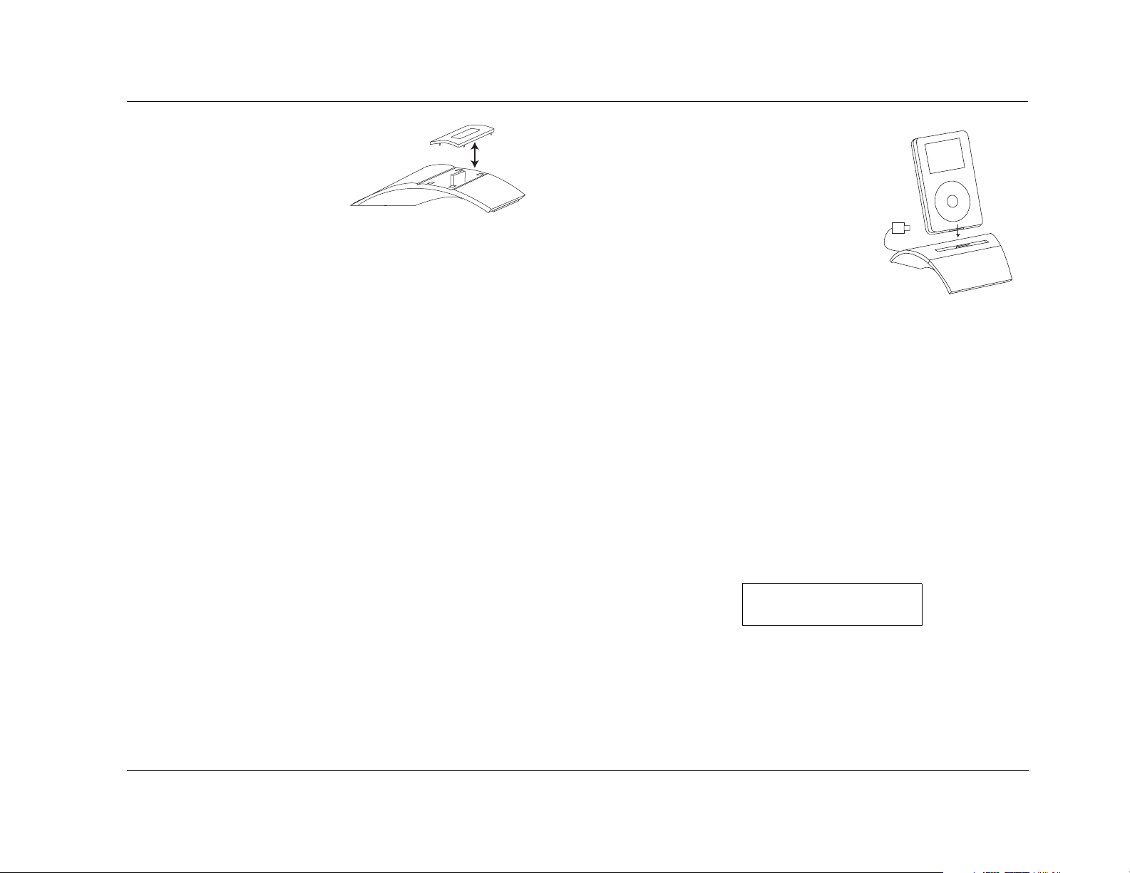
MV-5 PC & Dock Controls
To remove the factory installed
insert, hold the Dock with one
hand as you grab the edges of
the insert in the Dock with
your other hand, then pull
straight up. Use the following
as a guide to determine which
insert is correct for your iPod model:
• For any iPod with a color screen, including all iPod photo
models, use the insert with “COLOR/PHOTO” on the back.
This insert is already installed in the Dock at the factory.
• For 20GB or 30GB iPod photo models only, remove the insert
marked “COLOR/PHOTO” and attach the two included foam
pads to the rear inside wall in the well of the insert before
replacing it.
• For iPods with a black & white screen and a 10GB, 15GB, or
20GB hard drive, use the insert with “10GB/15GB” on the
back.
• For iPods with a black & white screen and a 30GB or 40GB
hard drive, use the insert with “30GB/40GB” on the back.
• Use the insert with “mini” on the back for all iPod mini models.
• Use the insert with “Universal” on the back for iPod models
that come with a special insert.
Once you have selected the correct insert, place it over the well in
the center of the Dock and gently press it down so that it snaps into
place.
Note: Do not place an iPod in the Dock unless an insert is installed;
otherwise the iPod will not connect properly and damage may occur to the
Dock and/or your iPod that is not covered by the warranty for either
product.
DOCKING THE iPOD
After placing the appropriate insert in the
center well of the Dock and connecting
the Dock to your receiver, dock your iPod
by placing it into the insert, gently
pressing it down until the connectors
mate between the iPod and the Dock.
Note: If you normally keep your iPod in a
protective case, or “skin”, you will need to
remove it before docking your iPod.
When the iPod is plugged into the Dock, the iPod navigation
controls are no longer accessible and the iPod screen will read
“Connected and ready to be unplugged“.
DOCK 2-LINE DISPLAY CHARACTERISTICS
When the DOCK input is selected, the 2-line front panel display
changes so that the left side of the display reflects the current iPod
information. Initially, the 2-line display on the MV-5 displays
“Menu” on the left side of the top line. “Playlists” and the number
of playlists available are displayed on the left side of the bottom
line. The ANLG signal type is identified on the top right side and
the current volume setting of the MV-5 is identified on the bottom
right side of the display, as shown:
MENU
PLAYLISTS 11
Note: The name of the iPod is always included as the first playlist.
ANLG
-39dB
5-5
Page 68

PC & Dock Controls Lexicon
As the menus on the iPod are scrolled through, the top left side
indicates the menu item selected and the bottom left side indicates
the menu items as they are scrolled through, as shown:
PLAYLIST 4
DINNER MIX
Note: The allotted space for iPod navigation descriptions is 14 characters. If
a menu item is longer that this limitation, the displayed name is simply cut
off at the 14-character point.
When a song is playing, the bottom of the 2-line display identifies
the track counter, the time left on the song, and whether the song
is in PLAY or PAUSE mode. The top left side of the display
continuously scrolls through the song title, artist, and album title, as
shown:
Title: Everybod...
0:57 -2:08
ANLG
-39dB
ANLG
-32dB
CONTROLLING THE iPOD WITH THE MV-5
To control the iPod once it is docked and connected to the MV-5,
use the remote control. Page 3 of the “LEX” menu layer of the
remote control touch screen is devoted to controlling the iPod.
• The IPOD+ option mimics the Skip Forward control. Pressing
this option causes the iPod to skip forward a track in the
playlist.
•The CLIKoption mimics a counter-clockwise click on the
iPod.
•The CLIKoption mimics a clockwise click on the iPod.
• The MENU option mimics the MENU button on the iPod. The
Menu button backs out of the menu structure, one level at a
time, each time it is pressed.
• The SEL option mimics the SELECT button on the iPod. The
SELECT button acts as a play button at the song level. The
select button drills deeper into the menu structure, one level a
time, each time it’s pressed.
•The
|| options mimic the Pause/Play control of the iPod. If the
playlist is not active, pressing either of these options starts the
playlist. If the playlist is already playing, then pressing this
option pauses it.
CHARGING THE iPOD
You may leave your iPod in the Dock even when you are not using
it as a playback source. Whenever the iPod is docked and the MV-5
is turned on, the Dock will charge the battery in the iPod.
Note: The following functionality is available only if there is a valid device
connected to the DOCK connector on the rear panel and the DOCK input
has been selected.
Using the MV-5 remote control:
• Page 3 of the “Lex” touch screen menu provides iPod controls
for use with the DOCK input.
• The IPOD- option mimics the Skip Back control. Pressing this
option causes the iPod to skip back a track in the playlist.
5-6
REMOVING THE iPOD
To remove the iPod from the Dock, grasp the sides of the iPod and
pull it straight up, away from the Dock.
Page 69

MV-5 PC & Dock Controls
ZONE 2 iPOD CONTROLS
The MV-5 Processor allows the DOCK input, and attached iPod, to
be accessed and output to either the Main Zone or the Zone 2
location. However, for the DOCK inputs, the OSD and front panel
display reflect ONLY the Main Zone activity. Therefore, if the iPod is
accessed in Zone 2, there is no visible indication on the MV-5 that a
change has been made.
To control the iPod in Zone 2 via the remote control:
1. From the “Zone 2” menu layer, select the DOCK input (num-
ber pad key 8).
2. Page 1 of the “Zone 2” menu layer touch screen provides the
iPod controls.
5-7
Page 70

PC & Dock Controls Lexicon
5-8
Page 71

6
Troubleshooting & Maintenance
Troubleshooting......................................................................... 6-2
MV-5 Error Messages.................................................................. 6-7
Video Error Messages ................................................................................ 6-7
Autocal Error Messages .............................................................................6-8
Video Resolutions Table............................................................ 6-10
Routine Maintenance ............................................................... 6-12
Restoring Factory Default Settings ............................................ 6-12
Page 72

Troubleshooting & Maintenance Lexicon
TROUBLESHOOTING
The MV-5 does not power on.
1. Make sure the rear panel power switch is set to the ON
position.
2. Attempt to power on the MV-5 with the front panel Standby
button and remote control ON button.
3. Examine the power cord to ensure a good connection between
the rear panel AC input connector and the wall outlet.
4. Check the electrical circuit and breaker.
The remote control does not work.
1. Make sure that the remote control touch screen is in the “LEX”
or “Zone 2” menu layers. The remote control is a universal
control designed to operate all of the home theater equipment
in your system. In order to control the MV-5, the remote
control must be in the “LEX” or “Zone 2” menu layers.
2. Eliminate obstructions between the remote control and the
front panel IR receiver. When the rear panel IR IN connector is
not in use, the remote control must be in line of sight with the
front panel IR receiver for proper operation. The remote control
might also become unreliable if strong sunlight or fluorescent
light is shining on the MV-5’s IR receiver.
3. Make sure the remote control batteries are correctly inserted
with the proper polarity.
The MV-5 is powered on, but there is no audio.
1. Make sure that the source device is powered on, playing audio,
and set to the right output connector.
2. Make sure the volume level is audible. Volume level can be
adjusted with the front panel volume knob or the remote
control VOL and buttons.
3. Make sure the audio has not been muted. The message “MUTE
ON” is displayed on the on-screen and front panel displays
when audio has been muted in the Main Zone. In addition, the
MUTE button on the front panel lights red when the Main Zone
mute is active and green when the Zone 2 mute is active. If
both Zones are muted, the Mute button lights amber. To
deactivate mute, press the MUTE button or adjust the volume
level.
4. Verify that all rear panel input and output connections are
correct.
5. Check the INPUT SETUP menu DIG AUDIO and ANLG AUDIO
parameters to ensure the appropriate audio connector is assigned
to the selected input.
6. Verify that the incoming audio signal is compatible with the input
chosen.
Note: The rear panel input connectors marked S/PDIF INPUTS (RCA
& TOSLINK connectors) are not compatible with MP3 sources.
The Subwoofer(s) distorts frequently.
4. Replace the remote control batteries. When the batteries are
low on power, the remote control enters a low-voltage
condition that prevents it from operating the MV-5.
5. If using the optional RF-1 Receiver, ensure that it is properly
connected to the MV-5 rear panel.
6-2
The likely cause for the subwoofer(s) to distort is either an
incorrectly set output level or the subwoofer high-pass filter is set
too low. Verify that the SUB/LFE LPF setting (subwoofer cross-over
point) is set correctly. If correct, try setting the SUB HPF setting to a
higher value to resolve the issue. Refer to Section 3: Setup for more
information.
Page 73

MV-5 Troubleshooting & Maintenance
A humming sound is present in the audio.
1. If a cable TV connection is present, disconnect the cable from
the wall outlet. If this eliminates the humming sound, a ground
loop isolation device is required. Contact your dealer or cable
provider for assistance.
2. Disconnect components one at a time to isolate the problem.
Once the problem is identified, make sure the associated
component is properly grounded and connected to the same
electrical circuit as the MV-5 Processor.
RF interference is present in the audio or video.
1. Make sure the MV-5 is not positioned too close to RF-emitting
devices.
2. Move such items one at a time to isolate which device is
causing the problem.
3. Replace unshielded cables with shielded cables wherever
possible.
Audio sounds distorted when using analog audio inputs.
The likely cause for distorted audio while using the analog audio
inputs is that the input voltage is too high. The MV-5 analog inputs
have a maximum rating of 2 Vrms. Any input voltages higher than
this limit will exhibit audible distortion.
In the SEMI AUTOCAL Test, the Far Field Test keeps failing.
1. Ensure that the microphone is placed in your preferred seating
location.
2. Ensure that the volume is set to -20dB.
3. In the Speakers Menu, ensure that none of the speakers
connected to the system have a cross-over selection of NONE.
During the Far Field Test, test tones are sent to ALL speaker
locations, regardless of the settings identified in the Speakers
menu. Therefore, every speaker that is plugged in MUST have
a cross-over setting other than NONE for the Far Field test to be
successul. If a cross-over is set to NONE but the speaker is
plugged in, the test will fail because it will “see” a speaker that
is identified as having no cross-over point.
4. Refer to the “AUTOCAL Error Messages” section found later in
this chapter for more information about specific error messages
related to the AUTOCAL process.
The volume won’t go to the +10 dB maximum level.
The speaker output level settings may affect the maximum volume
level of the MV-5 Processor. The maximum volume level is +10 dB
minus the maximum output level setting of any speaker. Thus, if
your front L/R output levels are set to +3 dB, the maxium allowable
volume level is +10 dB minus 3 dB, or +7 dB.
To correct the problem, reduce the analog audio output from the
connected device using the volume or level control. If neither is
available, an intermediate device may be required. Contact your
Lexicon dealer for assistance.
The picture on the video monitor is all one color.
This is a synchonization problem when using HDMI. When the
source device and video monitor do not sync correctly, the
color spacing may not load correctly. When the monitor color
is all red, or all green, it means that only half of the color
spacing data was loaded into the video monitor.
To correct the problem, simply enter the OSD menu and then exit
out again. This will resync the video and should clear the error.
6-3
Page 74

Troubleshooting & Maintenance Lexicon
The MV-5 is powered on, but there is no video.
1. Examine the video cables – particularly the S-Video cables –
to ensure a good connection to the associated component.
2. Check the INPUT SETUP menu VIDEO IN parameter to ensure
the appropriate video connector is assigned to the selected
input.
3. Set the V-PROCESS parameter to BYPASS. This setting doesn’t
apply any video processing and outputs the signal in the same
resolution and format as the incoming signal.
4. Refer to the “Video Error Messages” section found later in this
chapter for more information about specific video-related error
messages.
5. Verify that the selected output is not analog with a HDCP
(High-Bandwidth Digital Content Protection) input source.
Source material that carries HDCP encoding is only available
through the HDMI output. No video is output on the analog
output connectors.
6. Verify that the input type selected on the video monitor
matches the selected output on the MV-5.
Video is shifted to the left.
When the MV-5 has both component and HDMI cables connected to
a video monitor with the Faroudja processing active, the Faroudja
processing may cause the video to shift to the left when the
component output is selected, particularly at higher resolution
settings.
To correct the issue, change the Display CONNECTION parameter
from HDMI/DVI to ANALOG, or unplug the HDMI cable.
2. Use the or cursors to highlight SETUP and then press the
cursor, or press the SELECT button, to select the menu
option.
3. Using the cursors, highlight and select DISPLAY SETUP.
4. Then select CONNECTION. The parameter selection starts to
flash.
5. Use the or cursors to select ANALOG and then press the
cursor to save the selection.
6. Press EXIT to close the OSD menu.
The MV-5 is exhibiting erratic behavior.
1. Change to a different input, then return to the original input.
This may clear the discrepency.
2. Put the MV-5 into Standby mode. Wait 10 seconds. Then take
the MV-5 out of Standby mode.
3. Set the rear panel power switch of the MV-5 to the OFF
position. Wait 10 seconds. Then set the rear panel power switch
to the ON position.
4. With the MV-5’s rear panel power switch set to OFF, power-cycle
all other devices that are connected to the MV-5, such as DVD &
CD players, projectors, and monitors. When finished, restore
power to the MV-5 by setting the rear panel power switch to the
ON position and then taking the MV-5 out of Standby mode.
5. If the steps above do not resolve the behavior, document all
user-defined settings on the Installation Worksheet that begins
on page D-2. Then, follow the instructions found later in this
chapter to restore factory default settings.
To change the CONNECTION parameter:
1. Enter the OSD menu by pressing MENU on the remote control.
6-4
Page 75

MV-5 Troubleshooting & Maintenance
VIDEO IN is set to NONE, but the monitor has a video error, or
is showing a blue screen.
When the VIDEO IN parameter is set to NONE, the MV-5 outputs a
blue screen at 480i resolution. This blue screen cannot be disabled.
If the monitor does not support 480i resolution, the monitor may
display an error message.
Note: This condition can also exist when the VIDEO IN parameter
has been setup, but there is no active incoming signal.
The 2-line OSD display does not appear on the video monitor.
• Verify that the 2-line OSD parameter under the Setup -> Display
Setup -> On-Screen Display menu is not set to OFF.
• Verify the video input source. The 2-line OSD is supported only
at 480i and 576i resolutions when the incoming video source is
digital.
While using HDMI connections, the video monitor is behaving
oddly.
Connecting together all the components of your home theater
system with HDMI depends upon every piece of equipment
functioning in synchronization. If the timing of any one piece is out
of sync, then odd results can occur. For example, an out-of-sync
source might cause incorrect colors to appear on the screen, or to
shift all of the video to the left or towards the top of the screen. If
the video monitor sync is off, it might load the color spacing
incorrectly so that the screen appears to be all one color, instead of
displaying normal color. In short, an out-of-sync signal can cause a
number of very odd results.
sync issues don’t need a power cycle to re-sync correctly. We
suggest that you try the following:
1. Enter the OSD menu and then exit out again. This will resync
the video.
2. Put the MV-5 into Standby mode. Wait 10 seconds. Then take
the MV-5 out of Standby mode.
3. Power cycle the MV-5 by turning off the rear panel power
switch, wait at least 10 seconds, and then turn the rear panel
power switch to the ON position.
4. With the MV-5’s rear panel power switch set to OFF, power-cycle
all other devices that are connected to the MV-5, such as DVD &
CD players, projectors, and monitors. When finished, restore
power to the MV-5 by setting the rear panel power switch to the
ON position and then taking the MV-5 out of Standby mode.
The MV-5 is connected via USB to the PC but the computer is
playing with the sound card, not the MV-5.
This condition may exist if the media player was already active
when the USB cable was connected between the computer and the
MV-5 Processor. With the media player actively playing, it may not
“see” the USB connection. Close the media player, check the cable
connections, and then launch the media player again. Now it
should see the USB connection and switch control to the MV-5.
To correct the problem, the system needs to resync, which should
clear the error. Some out-of-sync issues are easier to clear than
others. Typically, power cycling the MV-5 will clear it, but some
6-5
Page 76

Troubleshooting & Maintenance Lexicon
Using the PC input, the remote control commands on page 4 of
the LEX menu and page 2 of the ZONE 2 menu do not work.
1. Make sure that the computer is properly connected to the USB
input of the MV-5 Processor.
2. Make sure that PC is selected as the active input on the MV-5
Processor.
3. Make sure that the media player has been opened on the
computer and is playing audio.
4. Make sure the media player is the “top” or active screen on the
computer. The MV-5 remote control will not operate the media
player if it is minimized or “behind” other programs.
CAUTION!
Do NOT power cycle the computer while connected to the
MV-5 with the PC input selected. The computer MUST be
on and connected to the MV-5 rear panel USB jack BEFORE
selecting the PC input on the MV-5. Selecting the PC
input first may cause a burst of loud noise that may be
damaging to the speakers or the listener’s hearing.
Harman Specialty Group assumes no responsibility for
damage caused in this manner.
The iPod does not play or respond to commands from the MV-5
remote control.
1. Make sure that the Dock is properly connected to the MV-5
Processor.
2. Make sure that the Dock is selected as the active input on the
MV-5 Processor.
3. Make sure that the touch screen of the MV-5 remote control is
in an iPod control page of the “LEX” or “ZONE 2” menu layer.
The iPod’s front panel display and controls do not operate
when the iPod is docked and the DOCK input is selected as the
MV-5’s active input.
This is normal behavior and does not indicate a problem with the
iPod, the Dock, or the MV-5 Processor. Use the MV-5 remote
control to navigate the iPod functions. Refer to Section 5: PC & Dock
Controls, for further information.
The iPod does not seem to be functioning correctly.
Verify the video input setting of the Dock input in use. If the video
input is set to an HDMI input source, the functionality of the iPod
may be hindered.
If all else fails...
1. Document all user-defined settings on the Installation
Worksheet that begins on page D-2. Then, refer to the
“Restoring Factory Default Settings” section found later in this
chapter to reset the MV-5 to the factory settings.
Note: If you want to save your settings before restoring the
factory defaults, you must save them manually. The Installation Worksheet in Appendix D has been provided to assist
you.
2. Contact an authorized Lexicon dealer.
3. Contact Lexicon customer service at www.lexicon.com or
781-280-0300.
Note: Visit the knowledgebase at http://www.lexicon.com/kbase for
answers to frequently asked questions and additional troubleshooting
information.
6-6
Page 77

MV-5 Troubleshooting & Maintenance
MV-5 ERROR MESSAGES
MV-5 error messages are displayed on the OSD when certain error
conditions exist. This section explains what each of these error
messages means and how to fix each problem.
VIDEO ERROR MESSAGES
The following error messages apply specifically to video issues.
VIDEO PROCESS ERROR
This error message will display
when the incoming datastream is
at a higher resolution than the
resolution of the VIDEO OUT
parameter. The MV-5 can
up-sample a lower resolution to a
higher resolution. However it can
not down-sample to a lower
resolution setting.
To correct the problem, right click to return to the VIDEO OUT
Setup parameter and change the VIDEO OUT parameter to AUTO
or to a resolution setting that is higher than that of the incoming
datastream.
VIDEO PROCESS NOTICE
Video input resolution
can not be higher than
video output resolution
when set to FAROUDJA.
Please adjust settings.
PRESS > TO CONTINUE
VIDEO FORMAT OUTPUT
ERROR
This error message will display
when the MV-5 is connected to an
HDMI video monitor but the
VIDEO OUT parameter is set to a
resolution that is not supported by
the HDMI video monitor.
To correct the problem, right click
to return to the VIDEO OUT Setup
parameter and change the VIDEO
OUT parameter to AUTO or to a
resolution setting that is supported
by the video monitor.
HDCP VIDEO ERROR
This error message will display
when the video monitor is not
HDCP compliant and the
incoming datastream requires
HDCP compliance. Typically, any
HDMI source will require a HDCP
compliant video monitor.
VIDEO OUTPUT NOTICE
Video output resolution
not supported by HDMI
monitor. Please select
a different VIDEO OUT
resolution.
PRESS > TO CONTINUE
HDCP NOTICE
Display is not
HDCP Capable
To correct the problem, change
the incoming datastream to a
non-HDCP source or change the
video monitor to one that is HDCP
compliant.
6-7
Page 78

Troubleshooting & Maintenance Lexicon
CHANGE MONITOR
MESSAGE
This error message flashes on the
2-line OSD and front panel display
when an analog signal is being sent
to an HDMI monitor.
To correct the problem, change the video monitor setting to an
analog input source.
CHANGE MONITOR TO
ANALOG IN
AUTOCAL ERROR MESSAGES
The following error messages apply specifically to error conditions
that exist during the AUTOCAL or SEMI AUTOCAL procedures, or
that pertain to the saved AUTOCAL settings.
MICROPHONE OVERLOAD
MICROPHONE OVERLOAD
ERROR
This error message will display
when the microphone is placed too
close to the speaker grille of the
speaker under test during the Far
Field, Near Field, or Subwoofer
Tests.
Verify microphone
position and
lower volume 6dB.
REPEAT TEST
BACK TO SPK/EQ SETUP
CAUTION!
If the microphone is too close to the speaker during
testing, damage to the speaker or microphone may
result.
FAR FIELD ERROR
This error message will display
when the microphone does not
detect sound from a speaker that
has a cross-over setting other than
“NONE” during the Far Field Test.
To correct the problem, check the
microphone position, verify the
speaker cables are connected
properly, verify that the volume
level is correct, and repeat the test.
NEAR FIELD ERROR
This error message will display
when the Near Field test has failed.
Typically, this failure occurs
because the microphone is not in
the proper position or the volume
setting is too low.
To correct the problem, verify that
the microphone is within two feet
of the speaker under test, verify the
speaker cables are connected
properly, verify that the volume
level is correct, and repeat the test.
FAR FIELD ERROR
Speakers detected:
FRT-L: NO SIDE-R: NO
CENTER: YES REAR-R: YES
FRT-R: YES REAR-L: YES
SIDE-L: YES
Verify mic position
and spkr connections.
If OK, raise volume 5dB.
REPEAT TEST
BACK TO SPK/EQ SETUP
NEAR FIELD AUTOCAL
ERROR
Verify mic position
and spkr connections.
If OK, raise volume 5dB.
REPEAT TEST
BACK TO SPK/EQ SETUP
To correct the problem, move the microphone further away from
the speaker under test and repeat the test.
6-8
Page 79

MV-5 Troubleshooting & Maintenance
SUBWOOFER CAL ERROR
This error message will display
when the Subwoofer test has
failed. Typically, this failure occurs
because the microphone is not in
the proper position or the volume
setting is too low.
To correct the problem, check the
microphone position, verify the
subwoofer cables are connected
properly, verify that the volume
level is correct, and repeat the test.
Note: If you are using a powered subwoofer, verify that it is
powered on.
CROSS-OVER CHANGE
SUBWOOFER CAL ERROR
Subwoofers detected:
SUBWOOFER 1: NO
SUBWOOFER 2: NO
Verify mic position
and sub connections.
If OK, raise volume 5dB.
REPEAT TEST
BACK TO SPK/EQ SETUP
CAUTION
WARNING
This warning message will display
the first time each speaker or
subwoofer cross-over is manually
changed from the AUTOCAL or
SEMI AUTOCAL settings.
Press the cursor button on the
remote control to clear the
warning message. When cross-over
changes are complete, run the
SEMI AUTOCAL procedure.
Changing these
settings will affect
the autocalibration.
Run SEMI AUTOCAL
after changes are made.
RETURN TO MENU
6-9
Page 80

Troubleshooting & Maintenance Lexicon
VIDEO RESOLUTIONS TABLE
2. If the incoming analog video signal is Macrovision protected, a
form of copy protection for analog sources, then the component
The MV-5 Processor is designed to allow flexibility in the selection of
video output resolutions. However, there are restrictions on what
resolutions can be made available due to incoming signal
limitations.
If you are not getting the expected resolution options for your
video monitor, it is possible that there is an incompatability
between the input setup selections and the incoming signal. The
table below describes those formats that are possible, given a
specific input source and input setup conditions.
Notes:
video output must be either 480i or 480p resolution. If the
output resolution setting has a value that is higher than 480p
resolution, then no analog signal is output.
3. If the HDMI is not connected when the incoming signal is a
Macrovision protected analog video, then the VIDEO OUT
parameter changes automatically to 480p resolution and only
component video is output.
4. The difference between BYPASS and CONVERSION options is
where the video encoder is used (CONVERSION) or not
(BYPASS) when the S-video or composite video input is selected.
In CONVERSION mode, digital video from the analog input is
The following notes refer to the “Note” column in the table.
1. If the incoming HDMI signal is copy-protected (HDCP), all
analog video output is blocked. All the available outputs that
provided to the video encoder and the S-video and composite
video outputs are encoded. In BYPASS mode, the analog input
signal goes to the video output directly, with no encoding.
may be affected by copy protection are noted in the table by a
double asterix (**).
INPUT
OUTPUT
Video Mode
Source Format HDMI Component S-Video Composite Note
HDMI
Component
Analog
S-Video,
Composite
Analog
480i
480p 480p ~ 1080i 480p ~ 1080i** - - 1
720p 720p ~ 1080i 720p ~ 1080i** - - 1
1080i 1080i 1080i** - - 1
480i 480p ~ 1080i 480p ~ 1080i 480i 480i 2, 3
480p 480p ~ 1080i 480p ~ 1080i** - - 2, 3
720p 720p ~ 1080i 720p ~ 1080i** - - 2, 3
1080i 1080i 1080i - - 2, 3
S-480i 480p ~ 1080i 480p ~ 1080i** 480i (from S) 480i (from S) 2, 3
C-480i 480p ~ 1080i 480p ~ 1080i** 480i (from C) 480i (from C) 2, 3
S&C - 480i 720p ~ 1080i 720p ~ 1080i 480i (from S) 480i (from S) 2, 3
FAROUDJA ON
480p ~ 1080i 480p ~ 1080i** 480i** 480i** 1
6-10
Page 81

MV-5 Troubleshooting & Maintenance
INPUT
OUTPUT
Video Mode
Source Format HDMI Component S-Video Composite Note
HDMI
Component
Analog
S-Video,
Composite
Analog
HDMI
Component
Analog
S-Video,
Composite
Analog
480i
480p 480p 480p** - - 1
720p 720p 720p** - - 1
1080i 1080i 1080i** - - 1
480i 480i 480i - - 2, 3
480p 480p 480p - - 2, 3
720p 720p 720p - - 2, 3
1080i 1080i 1080i - - 2, 3
S-480i 480i 480i** 480i (from S) 480i (from S) 2, 3, 4
C-480i 480i 480i - 480i (from C) 2, 3, 4
S&C - 480i 480i 480i 480i (from S) 480i (from S) 2, 3, 4
480i
480p 480p 480p** - - 1
720p 720p 720p** - - 1
1080i 1080i 1080i** - - 1
480i 480i 480i 480i** 480i** 2, 3
480p 480p 480p - - 2, 3
720p 720p 720p - - 2, 3
1080i 1080i 1080i - - 2, 3
S-480i 480i 480i 480i (from S) 480i (from S) 2, 3, 4
C-480i 480i 480i 480i (from C) 480i (from C) 2, 3, 4
S&C - 480i 480i 480i 480i (from S) 480i (from S) 2, 3, 4
BYPASS
CONVERSION
480i 480i** 480i** 480i** 1
480i 480i** 480i** 480i** 1
6-11
Page 82

Troubleshooting & Maintenance Lexicon
ROUTINE MAINTENANCE
The bulleted items below describe routine maintenance that should
be performed on a periodic basis.
• Clean the MV-5 exterior surface with a soft, lint-free cloth. Do
not use alcohol, benzene, acetone-based cleaners or strong
commercial cleaners. Do not use a cloth made with steel wool
or metal polish. If the MV-5 is exposed to a dusty environment,
a low-pressure blower can be used to remove dust from its
exterior surface.
• Replace the remote control batteries as needed. The remote
control requires four AAA batteries. When these batteries are
low on power, the remote control enters a low-voltage
condition that prevents it from operating the MV-5. Normal
operation will resume when new batteries are installed.
Note: The Remote Control will not lose any custom settings if the batteries run out. All custom settings are stored in non-volatile FLASH
memory.
RESTORING FACTORY DEFAULT SETTINGS
It is possible to reset the MV-5 Processor to its factory settings.
However, doing so will permanently delete any user-defined or
manually-entered settings, including parameters such as speaker
setup changes and input names.
Before performing a factory reset, be sure to use the
worksheets in Appendix D to record all of the input and setup
information. The factory reset WILL delete all custom settings
except for the saved EQ Presets.
To restore the factory default settings:
1. Record all parameters and user-defined settings on the
Installation Worksheet that begins on page D-2.
2. Put the MV-5 into Standby.
3. Press and hold the MUTE and ST/MON buttons at the same
time.
After several seconds, the MV-5 will turn on. The front panel display
will state “RESET” and then it will return to the normal display. All
parameters and user-defined values will now reflect the factory
default settings, with the exception of any saved EQ Presets.
Note: If you want to save your settings before restoring the factory
defaults, you must record them manually. The Installation Worksheet
in Appendix D has been provided to assist you.
6-12
Page 83

A
Appendix
Specifications ............................................................................. A-2
Declaration of Conformity.......................................................... A-4
Page 84

Appendix A Lexicon
SPECIFICATIONS
Inputs
HDMI (Version 1.1) 2 HDMI Type A, 19-pin connectors
Analog Video • Three component video, RCA connectors
• Four S-Video connectors
• Four composite video, RCA connectors
Digital Audio • Four S/PDIF coaxial (RCA) and four S/PDIF optical
(Toslink) connectors
• Coaxial & optical input connectors conform to IEC-958,
S/PDIF standards
• One USB mini-B connector
Analog Audio • One 8-channel input array, RCA connectors
• Six Stereo RCA connectors
• One microphone, 3.5mm mono mini plug
• 1 DOCK 30-pin connector (for optional docking station)
Control • One RS-232, 9-pin, D-sub connector
• One IR receiver, on front panel
• One 3.5mm IR IN jack:
Input Voltage: 3V - 15V
Input Current: 10mA
Frequency: 20Hz - 1KHz
Accepts either stereo plug (Tip/Ring/Sleeve) or mono
plug (Tip/Sleeve)
Outputs
HDMI (Version 1.1) One HDMI Type A, 19-pin connector
Analog Video • One component video, RCA connector
• One S-Video connector
• One composite video, RCA connector
Analog Audio • One 8-channel preamplifier plus additional subwoofer,
RCA connectors
• Zone2 Analog Out: 1 RCA Stereo connector
Control Two triggers - one power on/off & one programmable
3.5mm mono mini plugs
12VDC, 300mA maximum output draw
HDMI Performance
HDMI Input Video: 480i/p, 576i/p, 720p, or 1080i
HDMI Output Video: 480i/p, 576i/p, 720p, or 1080i
Audio: Dolby Digital, DTS, & PCM (32, 44.1, 48, 88.2, 96kHz,
176.4kHz, and 192kHz)
Audio: Dolby Digital, DTS, & PCM (32, 44.1, 48, 88.2, 96kHz,
176.4kHz. and 192kHz)
S-Video& Composite Video Performance
Compatibility NTSC, PAL, and SECAM
A/D converter 12-bit, 110MHz
D/A converter 12-bit, 74.25MHz
Input Level /
Impedance
Output Level /
Impedance
Frequency Response Composite: 10Hz to 8MHz, -3dB
Signal-to-Noise Ratio >65dB
Differential Gain <0.2%
Differential Phase <0.5 degrees
Gain +/- 0.15dB
1V peak-to-peak/75Ω
1V peak-to-peak/75Ω
S-Video: 10Hz to 8MHz, -3dB
Component: 10Hz to 100MHz, -3dB
Component Video Performance
Compatibility 3-channel (Y, Pr, Pb), format-independent
Impedance 75Ω
Insertion Loss <3dB
Bandwidth >100MHz
A-2
Page 85

MV-5 Appendix A
Main Zone & Zone 2 Audio Performance
A/D conversion 24-bit, 96kHz, dual-bit ΔΣ
D/A conversion 24-bit, 44.1 to 192kHz, multi-bit ΔΣ
Input Sensitivity 200mV for Analog 1 to 6, and 200mV for 8-ch input
max input level: 2Vrms
Input Impedance 98.5kΩ for Analog 1 to 6, and 32kΩ for 8-ch input
Frequency Response 10Hz to 40kHz, +0, -2dB
THD + Noise <0.05%, 20Hz to 20kHz
Dynamic Range 100dB typical, 22 kHz bandwidth
Signal-to-Noise Ratio 100dB typical, 22kHz bandwidth
min 100dBA, 103dBA typical
Output Level 200mV typical, 6Vrms maximum
Output Impedance 570Ω
General
Power Requirements 90-250VAC, 50-60Hz, 50W (Universal line input)
IEC detachable power cords (supplied)
Power Consumption 3.76W at Power on, idle
47.2W at rated power output (HDMI in/out mode)
Dimensions • Height (with feet): 5.0 inches (127 mm)
• Height (without feet): 4.3 inches (109 mm)
• Width: 16.8 inches (426 mm)
• Depth*: 16.7 inches (423 mm)
Weight • Net Weight: 17.6 lb (8 kg)
Rack-Mounting Lexicon built rack mount kit not available.
Operating
Environment
Remote Control Hand-held, back-lit, IR/RF** pre-programmed and learning
*Depth measurement includes knobs, buttons, and terminal connections.
**For use with optional RF-1 Receiver.
• Gross Weight: 26.5 lb (12 kg)
Please seek alternative.
• Operating temperature: 0 to 45 C (32 to 113 F)
• Storage temperature: -20 to 60 C (-4 to 140 F)
• Relative humidity: 93% max without condensation
remote control (requires 4 AAA batteries – included)
Specifications are subject to change without notice.
A-3
Page 86

Appendix A Lexicon
DECLARATION OF CONFORMITY
Application of Council Directive(s):
2004/108/EEC and 73/23/EEC as amended by 93/68/EEC
Standard(s) to Which Conformity is Declared:
EN 55013:2001 + A1:2003
EN 55020:2002 + A1:2003 + A2:2005
EN 61000-3-2:2000 + A2:2005
EN 61000-3-3:1995 + A1:2001
EN 60065:2002
Manufacturer: Harman Specialty Group
3 Oak Park
Bedford, MA 01730-1413 USA
The equipment identified here conforms to the
Directive(s) and Standard(s) specified above.
Type of Equipment: Digital Receiver
Model: Lexicon MV-5
Date: June 2007
Harman Specialty Group
Vice President of Engineering
3 Oak Park
Bedford, MA 01730-1413 USA
Tel: 781-280-0300
Fax: 781-280-0490
A-4
Page 87

B
Appendix
Main Menu: Audio Controls ........................................................B-2
Main Menu: Video Status ............................................................B-2
Main Menu: Setup ......................................................................B-3
Setup Menu: Display Setup....................................................................... B-4
Setup Menu: Surround Config .................................................................. B-4
Setup Menu: Speaker/EQ Setup
Setup Menu: Input Setup.......................................................................... B-6
...........................................................................B-5
Note: All parameter values shown in the following menu trees indicate the
default parameter value if the MV-5 is restored to its factory default
state.
Page 88

Appendix B Lexicon
MAIN MENU: AUDIO CONTROLS
MAIN MENU
AUDIO CONTROLS
VIDEO STATUS
SETUP
MAIN MENU: VIDEO STATUS
MAIN MENU
AUDIO CONTROLS
VIDEO STATUS
SETUP
VIDEO STATUS
INPUT RESOL: - - -
COPY PROTECTION: OFF
V-PROCESS: FAROUDJA
OUTPUT RESOL: - - COMPONENT OUT: 480i
S-VIDEO OUT: OFF
COMPOSITE OUT: OFF
AUDIO CONTROLS
AUTO EQ: ON
EQ PRESET
EQ ADJUST
TONE CONTROLS: OFF
BASS: 0dB
TREBLE: 0dB
AUDIO STATUS
EQ ADJUST
HF SHELF: 0dB
AUDIO STATUS
INPUT: HD+
NAME:
CONNECTOR: ANALOG 3
AUDIO: - - MODE FAMILY: LOGIC 7
MODE: MUSIC 5.1
EQ PRESET
ACTIVE PS: USER
PRESET 1: FACTORY
PRESET 2: FACTORY
PRESET 3: FACTORY
B-2
Page 89
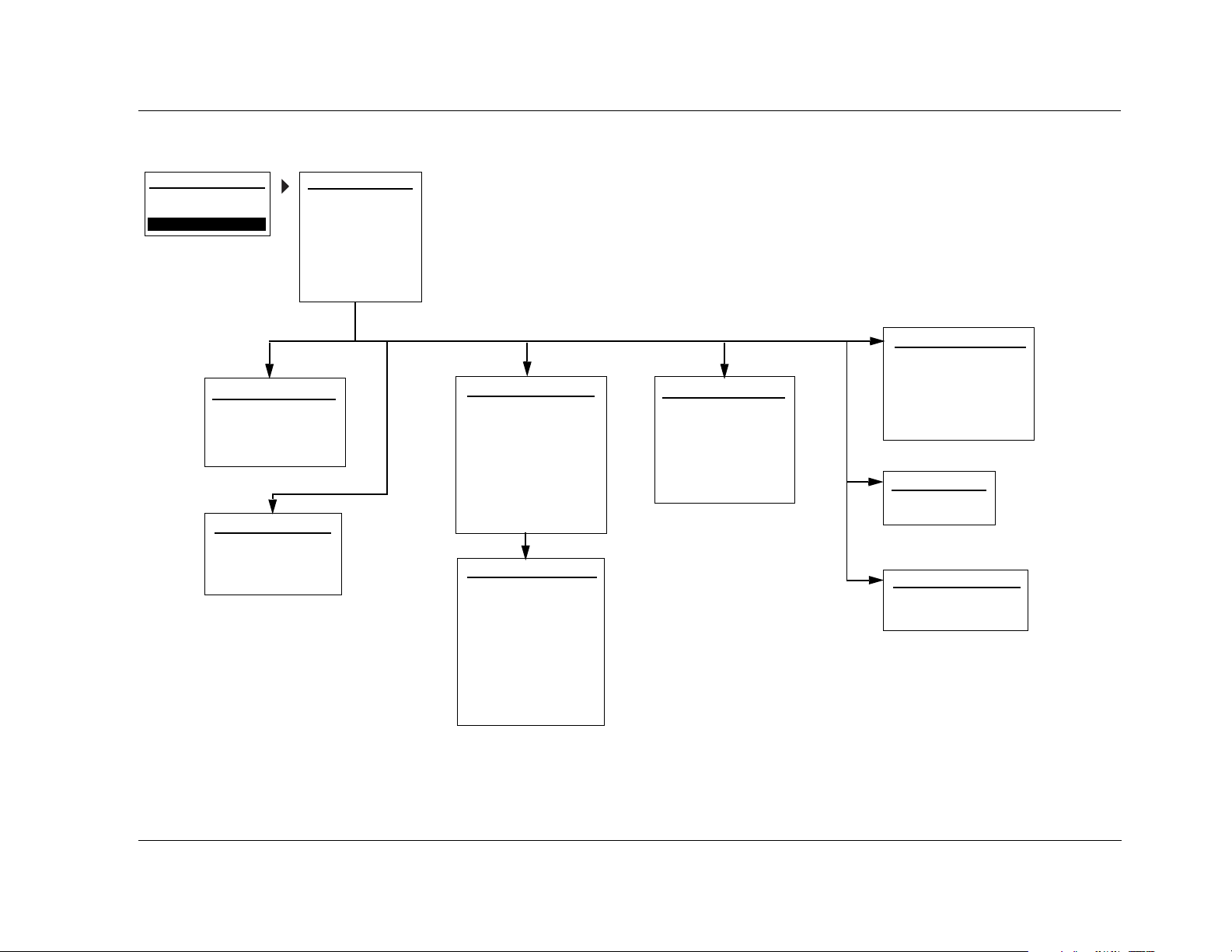
MV-5 Appendix B
MAIN MENU: SETUP
MAIN MENU
AUDIO CONTROLS
VIDEO STATUS
SETUP
DISPLAY SETUP
CONNECTION: HDMI/DVI
HDMI AUDIO OUT: NO
ON-SCREEN DISPLAY
FRONT PANEL DISPLAY
continued on page B-4
SPEAKER/EQ SETUP
MANUAL
SEMI AUTOCAL
FULL AUTOCAL
continued on page B-5
SETUP
DISPLAY SETUP
SPEAKER/EQ SETUP
INPUT SETUP
SURROUND CONFIG
DOLBY CONFIG
MUTE LEVELS
POWER ON SETTINGS
INPUT SETUP 1
INPUT: HD
NAME: ________
VIDEO IN: HDMI 1
V-PROCESS: FAROUDJA
VIDEO OUT: AUTO
DIG AUDIO: HDMI 1
ANLG AUDIO: NONE
DIG/ANLG AUTO: ON
INPUT SETUP 2
MODE FAMILY: LOGIC 7
MODE: FILM 5.1
DEFAULT SUR: STANDARD
A/D SAMPLE RATE: 48kHz
A/V SYNC DELAY: 0 ms
ADVANCED VIDEO
TRIGGER 2: OFF
ZONE-2 OUT: ANALOG
continued on page B-6
SURROUND CONFIG
LOGIC 7 DEFAULT: ON
DOLBY MULTI-CHANNEL
DOLBY 2.0
DTS
PCM 44.1/48 kHz
PCM 96kHz
continued on page B-4
DOLBY CONFIGURATION
MODE: DOLBY PLII MUSIC
CENTER WIDTH: 3
DIMENSION: 0
PANORAMA: OFF
NIGHT: OFF
MUTE LEVELS
MAIN ZONE: -30dB
ZONE-2: -30dB
POWER ON SETTINGS
POWER ON VOL: -30dB
DOCK AUTO POWER: ON
B-3
Page 90

Appendix B Lexicon
SETUP MENU: DISPLAY SETUP
MAIN MENU
AUDIO CONTROLS
VIDEO STATUS
SETUP
SETUP
DISPLAY SETUP
SPEAKER/EQ SETUP
INPUT SETUP
SURROUND CONFIG
DOLBY CONFIG
MUTE LEVELS
POWER ON SETTINGS
SETUP MENU: SURROUND CONFIG
MAIN MENU
AUDIO CONTROLS
VIDEO STATUS
SETUP
SETUP
DISPLAY SETUP
SPEAKER/EQ SETUP
INPUT SETUP
SURROUND CONFIG
DOLBY CONFIG
MUTE LEVELS
POWER ON SETTINGS
SURROUND CONFIG
LOGIC 7 DEFAULT: ON
DOLBY MULTI-CHANNEL
DOLBY 2.0
DTS
PCM 44.1/48 kHz
PCM 96kHz
DISPLAY SETUP
CONNECTION: HDMI/DVI
HDMI AUDIO OUT: NO
ON-SCREEN DISPLAY
FRONT PANEL DISPLAY
ON-SCREEN DISPLAY
2-LINE OSD: 3s
MENU TIME OUT: 30s
FRONT PANEL DISPLAY
BRIGHTNESS: FULL
TIME OUT: NONE
DTS
DTS 96/24: ON
DTS NEO:6: ON
DTS-ES MATRIX: ON
DTS-ES DISCRETE: ON
LOGIC 7: ON
STEREO DOWN MIX: ON
DOLBY 2.0
DOLBY PLII: ON
DOLBY PLIIx: ON
DOLBY VIRTUAL: OFF
LOGIC 7: ON
DOLBY MULTI-CHANNEL
DOLBY VIRTUAL: OFF
LOGIC 7: ON
STEREO DOWN MIX: ON
B-4
PCM 96kHz
LOGIC 7: ON
DOLBY PLII: ON
DOLBY PLIIx: ON
DTS NEO:6: ON
5/7 CH STEREO: ON
PCM 44.1/48 kHz
LOGIC 7: ON
DOLBY PLII: ON
DOLBY PLIIx: ON
DOLBY VIRTUAL: OFF
DTS NEO:6: ON
HALL: ON
5/7 CH STEREO: ON
Page 91

MV-5 Appendix B
SETUP MENU: SPEAKER/EQ SETUP
MAIN MENU
AUDIO CONTROLS
VIDEO STATUS
SETUP
SETUP
DISPLAY SETUP
SPEAKER/EQ SETUP
INPUT SETUP
SURROUND CONFIG
DOLBY CONFIG
MUTE LEVELS
POWER ON SETTINGS
SPEAKER/EQ SETUP
MANUAL
SEMI AUTOCAL
FULL AUTOCAL
MANUAL
SPEAKERS
SPEAKER DISTANCES
OUTPUT LEVELS
PERFORMS SEMI-AUTOMATIC
CALIBRATION
PERFORMS FULL AUTOMATIC
CALIBRATION
SPEAKER DISTANCES 1
AUTO SETTINGS: OFF
UNITS: FEET
FRONT LEFT: 0.0 ft
CENTER: 0.0 ft
FRONT RIGHT: 0.0 ft
SIDE RIGHT: 0.0 ft
REAR RIGHT: 0.0 ft
REAR LEFT: 0.0 ft
OUTPUT LEVELS 1
AUTO SETTINGS: OFF
INPUT: ALL
TEST TONE: OFF
FRONT LEFT: 0dB
CENTER: 0dB
FRONT RIGHT: 0dB
SIDE RIGHT: 0dB
REAR RIGHT: 0dB
SPEAKERS
AUTO SETTINGS: OFF
FRONT L/R: 80Hz
CENTER: 80Hz
SIDE L/R: 80Hz
REAR/Z2 L/R: 80Hz
SUB/LFE LPF: 80Hz
SUBWOOFERS: 1
SUB HPF: 20Hz
SUB MODE: NORMAL
SPEAKER DISTANCES 2
SIDE LEFT: 0.0ft
SUBWOOFERS: 0.0 ft
OUTPUT LEVELS 2
RIGHT LEFT: 0dB
SIDE LEFT: 0dB
SUBWOOFER1: 0dB
SUBWOOFER2: 0dB
B-5
Page 92

Appendix B Lexicon
SETUP MENU: INPUT SETUP
MAIN MENU
AUDIO CONTROLS
VIDEO STATUS
SETUP
SETUP
DISPLAY SETUP
SPEAKER/EQ SETUP
INPUT SETUP
SURROUND CONFIG
DOLBY CONFIG
MUTE LEVELS
POWER ON SETTINGS
INPUT SETUP 1
INPUT: HD*
NAME: ________
VIDEO IN: HDMI 1*
V-PROCESS: FAROUDJA
VIDEO OUT: AUTO
DIG AUDIO: HDMI 1*
ANLG AUDIO: NONE*
DIG/ANLG AUTO: ON
INPUT SETUP 2
MODE FAMILY: LOGIC 7
MODE: FILM 5.1**
DEFAULT SUR: STANDARD
A/D SAMPLE RATE: 48kHz
A/V SYNC DELAY: 0 ms
ADVANCED VIDEO
TRIGGER 2: OFF
ZONE-2 OUT: ANALOG
ADVANCED VIDEO 1
INPUT TYPE: DVD
SHARPNESS: 32
NOISE REDUCTION: OFF
X-COLOR SUPPRESS: ON
DCDi INTERPOL: ON
FILM DETECTION: ON
FILM EDIT DETECT: ON
ADVANCED VIDEO 2
FLESHTONE NR: ON
COMPNT ENHANCE: ON
BRIGHTNESS: 100
CONTRAST: 100
COLOR: 100
*Audio/Video Input Factory Default Settings:
PARAMETER HD DVD GAME SAT CABLE DVR CD DOCK PC TUNER AUX 1 AUX 2
VIDEO IN
DIG AUDIO IN
ANLG AUDIO IN
HDMI 1 Component 1 S-Video 1 Component 2 HDMI 2 Component 3 None None None None S-Video 2 S-Video 3
HDMI 1 Coaxial 1Optical 1Coaxial 2 HDMI 2 Coaxial 3 Coaxial 4 None USB None Optical 2 Optical 3
None None None None None None None Unplugged None None None None
**Mode Input Factory Default Settings for Each Mode Family:
LOGIC 7 (L7) DOLBY DSP STEREO (STER) DTS
FILM 5.1
PLII MOVIE HALL 1 5CH 2-CHANNEL NEO:6 5CH CINEMA
B-6
Page 93

C
Appendix
Remote Control Programming ................................................... C-2
Remote Control Light Button .................................................................... C-2
Transmitting Icon......................................................................................C-2
Setting Up the Remote Control.................................................................C-3
Lock Feature ............................................................................................. C-6
Advanced Customizing Tools .................................................................... C-6
Erasing Commands.................................................................................C-13
Restoring Factory Default Settings...........................................................C-14
Optional RF-1 Receiver ............................................................. C-14
Using the 3-Digit Code Library................................................. C-15
3-Digit Pre-programmed Codes ..............................................................C-15
Page 94

Appendix C Lexicon
REMOTE CONTROL PROGRAMMING
The MV-5 remote control is a very powerful and flexible
pre-programmed and learning remote control, designed to be the
universal controller of your home theater system.
The MV-5 remote control can operate up to 14 home entertainment
and home automation components by using the remote control’s
pre-programmed code library, or by letting the remote control “learn”
from another remote, one button at a time. The MV-5 remote control
has many additional operating features to add convenience and
enjoyment to the operation of any home entertainment system. You
can create your own button labels on the LCD screen; program forty
favorite channel buttons; operate the volume, channel and transport
buttons from one device when you are controlling another device; and
perform multiple tasks with the press of a single button.
The MV-5 remote control features extensive pre-programmed IR codes
for practically all major audio and video equipment. It can set up and
operate various components by simply entering a 3-digit code.
REMOTE CONTROL LIGHT BUTTON
The remote control is fully back lit, making it easy to use in low
lighting conditions. Press the LIGHT button on the right side of the
remote to back light all of the keypad buttons and the LCD touch
screen. To turn off the back light, press the LIGHT button again or
just stop pushing buttons. Ten seconds after the last button or
touch screen selection, the back light automatically shuts off.
TRANSMITTING ICON
When a command is transmitted by the remote control, a
transmit icon appears in the top right corner of the LCD
touch screen. This indicates that a signal is being sent by
the remote control.
LCD TOUCH
SCREEN
MENU
OPTIONS
POWER OFF
VOLUME +/-
MUTE
MENU
TRANSPORT
FUNCTIONS
NUMBER
KEYPAD
MENU NAME
(Location of)
TRANSMITTING
ICON
LIGHT
MENU PAGES
POWER ON
MAIN
CHANNEL +/-
PREV CH
GUIDE & INFO
EXIT
SELECT
ENT (Enter)
C-2
Page 95

MV-5 Appendix C
SETTING UP THE REMOTE CONTROL
The MV-5 remote control can be set up so that it controls all of the
components of your home entertainment system, making remote
access simple and efficient. There are two ways to set up the remote
control:
• Pre-programmed Codes - Allows you to set up all of the buttons at once, by entering the pre-programmed 3-digit codes of
the component manufacturers.
• Button Learning - Allows you to transfer functions from other
remotes, both old and new, one button at a time.
Of the two methods, the pre-programmed codes method is the
fastest, since all functions are programmed at the same time. However,
it’s possible that a 3-digit code may not be available for your
component. We recommend that you start with the pre-programmed
code method and then perform the button learning method as
necessary.
Pre-Programming Your Remote Control:
Follow the steps below to set up your MV-5 remote control using the
pre-programmed manufacturers’ codes.
The pre-programmed 3-digit codes for each component and
manufacturer can be found at the back of this Appendix. The codes are
listed by Component Category, such as TV, VCR, and DVD; then by
brand name, such as Lexicon and Samsung.
1. Find the code listing for the component that you want to set up in
the Pre-Programmed Codes library, found later in this chapter. If
there is more than one code, be sure to note all of them as your
component will only fully respond to one of them, so you may
have to try multiple codes.
Note: 305 is the factory default setting for the Lexicon RT-20 Universal
Disc Player.
2. Turn on the component that you want to setup for remote
control.
3. On the remote control, press and hold the MAIN and ENT (Enter)
buttons at the same time. After about 3 seconds, “SETUP” is
displayed in the Menu name area at the top of the LCD touch
screen. This is the Setup mode of the remote control.
NOTE: You now have 30 seconds to perform the next step while the
remote is in the Setup mode. If a button is not pressed within 30
seconds, the SETUP menu name will revert to MAIN, indicating that
the remote control is no longer in Setup mode. If this occurs, you will
need to repeat this step to re-enter the Setup mode.
4. Touch the P-PRO option to select the Pre-Programmed Method.
The menu name changes to “P-PRO” and the menu options area
now contains seven component options.
Note: While in the Setup mode, the MAIN button acts as an escape
button. Each time the MAIN button is pushed, it will back out of one
menu layer.
5. Select the component that you want to program. If the
component you wish to setup is not on this page, touch the menu
page arrow to select from the components on page 2.
Once a selection is made, the bottom of the screen flashes
“FROM TABLE”.
6. Confirm your component selection by pressing the button again
for the type of component you want to program.
Note: This step is necessary because the selection may not be the
same for Steps 5 and 6. For example, if you are setting up the SAT
option to be a second TV, then the first press in Step 5 would have
been SAT and the second press in Step 6 would then be TV.
7. Point the remote control at the component you want to program
and enter the first of the 3-digit manufacturer’s codes using the
number keypad on the remote.
If the 3-digit code that you entered is the correct one, the
component will turn off. If the component does not turn off,
continue entering code numbers from your list until the
component turns off.
C-3
Page 96

Appendix C Lexicon
Note: The DOWN and UP buttons on the touch screen can be used to
scroll the code number one digit at a time. If you hold your finger over
the UP or DOWN button, the code number will scroll until your finger
is removed.
8. When the component turns off, press the ON button on the
remote to turn the component back on. Test several functions to
ensure that the component responds correctly to the remote
commands. If any of the buttons do not work properly, you may
not have the right code - enter the next code option on your list
until you find the best match for the component.
Note: If you are unable to find a code that will accurately control your
component, then you’ll need to use the Button Learning procedure,
which follows this procedure, to program the component.
9. Once you’ve found the right code, touch the SAVE option on the
touch screen. The screen will blink “SAVED” two times, indicating
that the code has been successfully saved.
10. Exit the Setup mode by pressing the MAIN button until the touch
screen displays MAIN in the menu heading area. The remote
control is in normal operation mode again.
11. Repeat Steps 1 through 10 to program all other components in
your home theater system. For any components that do not have
a valid 3-digit code, continue to the Button Learning procedure to
program those components.
Recalling Pre-Programmed Setup Code Numbers:
In case you didn’t write down the pre-programmed code numbers
that you used when you set up your Lexicon remote controls, these
3-digit manufacturers’ numbers can be recalled. Perform the
following procedure to recall the pre-programmed 3-digit code for
any component.
displayed in the Menu name area at the top of the LCD touch
screen. This is the Setup mode of the remote control.
NOTE: You now have 30 seconds to perform the next step while the
remote is in the Setup mode. If a button is not pressed within 30
seconds, the SETUP menu name will revert to MAIN, indicating that
the remote control is no longer in Setup mode. If this occurs, you will
need to repeat this step to re-enter the Setup mode.
2. Touch the RECAL option. The touch screen now shows a four-page
menu that lists each component name and the 3-digit code that
was assigned to it.
3. Write down the code number for each component for future
reference. Appendix D of this manual provides a convenient table
for you to record the 3-digit pre-programmed code numbers.
4. Exit the Setup mode by pressing the MAIN button until the touch
screen displays MAIN in the menu heading area. The remote
control is in normal operation mode again.
Button Learning Procedure For Your Remote Control:
Follow the steps below to set up your MV-5 remote control using the
Button Learning procedure. The MV-5 remote control can “learn”
commands from other remote controls, both old and new, one button
at a time. Follow the steps below to allow your MV-5 remote control to
learn the button commands from other remote controls in your home
theater system.
Note: We recommend that you use this procedure only after you’ve
determined that no 3-digit manufacturers’ codes exist for the component
in question.
1. On the remote control, press and hold the MAIN and ENT (Enter)
buttons at the same time. After about 3 seconds, “SETUP” is
C-4
Page 97

MV-5 Appendix C
1. Line up the MV-5 remote control with the other remote control,
head-to-head, one or two inches apart.
2. On the MV-5 remote control, press and hold the MAIN and ENT
(Enter) buttons at the same time. After about 3 seconds, “SETUP”
is displayed in the Menu name area at the top of the LCD touch
screen. This is the Setup mode of the remote control.
NOTE: You now have 30 seconds to perform the next step while the
remote is in the Setup mode. If a button is not pressed within 30
seconds, the SETUP menu name will revert to MAIN, indicating that
the remote control is no longer in Setup mode. If this occurs, you will
need to repeat this step to re-enter the Setup mode.
3. Touch the LEARN option to select the Button Learning Method.
The menu name changes to “LEARN” and the menu options area
now contains seven component options. The bottom of the
screen flashes “SELECT”.
4. Select the component that you want to program. If the
component you wish to setup is not on this page, touch the menu
page arrow to select from the components on page 2.
Once a selection is made, the menu name changes to the
selected component name.
If you want to teach any command to a component button on
the MV-5 remote control, press the component button when
the menu name says “LEARN”. The menu name will change to
“READY” and the menu page area indicates the button that you
pressed. If you pressed the wrong button, press the MAIN
button to return to the Setup menu where you can start again
(return to Step 3). Once “READY” is displayed, skip ahead to
Step 6.
5. Select the component option that you want to teach the
command to - everything except for the MAIN button and the
menu page arrows can be taught. The menu name will change
to “READY” and the menu page area indicates the button that
you pressed.
6. Press and hold the button on the other remote control that you
want to teach to the MV-5 remote. When the menu name on the
touch screen of the MV-5 remote control changes to “GOOD” or
“FAILD”, release the button.
If “GOOD” is displayed, the bottom of the screen flashes
“SAVED”. The learning procedure is complete and was
successful.
If “FAILD” is displayed, try teaching the same button once
again by repeating Steps 5 & 6.
7. Repeat Steps 4 through 6 to teach the MV-5 remote control any
additional button commands from the component’s remote. To
return to Step 4, press the MAIN button once.
8. When you are done teaching the Lexicon remote control, exit the
Setup mode by pressing the MAIN button until the touch screen
displays MAIN in the menu heading area. The remote control is in
normal operation mode again.
Test all your new commands. If any of them don’t work, try the button
learning procedure again, keeping in mind the following suggestions:
• Move to another room. Plasma TVs, sunlight, halogen, or
quartz lighting can interfere with the learning process.
• Even though the old remote seems to be working fine,
replace the current batteries with fresh alkaline batteries.
• Gradually vary the distance between the remote controls.
Try 1-inch, 2-inches, and so on up to 4-feet.
• Try tapping the button on your old remote instead of just
pressing and holding it during the learning process.
The following list provides additional information regarding the button
learning procedure and how the MV-5 remote control behaves when
taught.
C-5
Page 98

Appendix C Lexicon
• Learned functions override any existing pre-programmed
functions on the remote control.
• All buttons can be taught except for the menu page arrows,
MAIN button, and LIGHT button on the side of the remote.
• Learned functions are automatically erased when a new
function is learned on the same button.
• Learned functions are retained even after a different
pre-programmed 3-digit manufacterer’s code is entered and
saved to the remote.
• To return to an original pre-programmed function, the learned
function must be erased.
LOCK FEATURE
The MV-5 remote control has a locking feature, which prevents
unauthorized use of the remote control. When the locking feature is
active, all operations of the remote control are blocked. This feature
can be used as a “child-lock” to prevent children from having
unmonitored access to the home theater system.
To Activate the Lock Feature:
Press and hold the +10 and ENT (Enter) buttons at the same time. After
3 seconds, the bottom of the touch screen will blink “LOCKED” three
times and then “LOCKED” will remain displayed. The Lock is now
active.
ADVANCED CUSTOMIZING TOOLS
Once the basic setup to your remote is complete, you can use the
advanced features to further customize your MV-5 remote control. The
advanced customizing tools include:
• back light Options - Customize the back light feature to suit
your preferences.
• Touch Screen - Customize the displayed text for each device
menu on the LCD touch screen.
• Favorite Channels - Set up your favorite channel list. Once this
list is set up, up to 40 favorite channels can be selected by the
press of a button - all without needing to remember or type in
a channel number.
• Macros - Power all of your components ON or OFF at the same
time, with the press of one button.
• Remote Cloning - Clone other MV-5/RV-5 remote control from
an already setup remote.
• Punch Throughs - Force buttons to work for specific devices,
regardless of the device currently selected on the MV-5 remote
control.
• Hiding & Adding Pages - Customize the visible pages on the
touch screen display.
To Return to Normal Operation:
While the remote is in the LOCKED condition, press and hold the +10
and ENT (Enter) buttons at the same time. After 3 seconds, the
“LOCKED” message is replaced by the last used mode is displayed. The
Lock is now deactivated.
C-6
Page 99

MV-5 Appendix C
back light Time Out:
The back light feature lights the touch screen area and illuminates the
buttons whenver the LIGHT button is pressed. The amount of time the
back light remains on before timing out can be adjusted to your
preferences. Follow the instructions below to change the back light
time out setting.
1. On the remote control, press and hold the MAIN and ENT (Enter)
buttons at the same time. After about 3 seconds, “SETUP” is
displayed in the Menu name area at the top of the LCD touch
screen. This is the Setup mode of the remote control.
NOTE: You now have 30 seconds to perform the next step while the
remote is in the Setup mode. If a button is not pressed within 30
seconds, the SETUP menu name will revert to MAIN, indicating that
the remote control is no longer in Setup mode. If this occurs, you will
need to repeat this step to re-enter the Setup mode.
2. Touch the menu page arrow to access the second page of the
SETUP menu.
3. Press the LIGHT button to customize the back light time out
setting. A new screen now displays ON, 10, SAVE, and EXIT. The
bottom of the touch screen says “SECOND” and there’s a flashing
box over the “1” digit. The current setting for the back light time
out is “10” seconds.
4. Use the number keypad to enter a new time. The setting range is
01 to 99 seconds. To turn the back light feature off, which saves
battery life, touch the ON option. The ON button changes to OFF
and the time is dashed out.
5. Touch the SAVE option to save the new setting. Touching the EXIT
option will leave the menu without saving any changes.
6. When finished, exit the Setup mode by pressing the MAIN button
until the touch screen displays MAIN in the menu heading area.
The remote control is in normal operation mode again.
Adjusting the Touch Screen Contrast:
You can make the text in the touch screen area darker by pressing the
MAIN and cursor buttons at the same time. To make the text
appear lighter, press the MAIN and cursor buttons at the same time.
Customizing the Touch Screen:
The LCD touch screen component names and commands can be
customized to your preferences. Follow the instructions below to
change the text in a selected touch screen menu.
1. On the remote control, press and hold the MAIN and ENT (Enter)
buttons at the same time. After about 3 seconds, “SETUP” is
displayed in the Menu name area at the top of the LCD touch
screen. This is the Setup mode of the remote control.
NOTE: You now have 30 seconds to perform the next step while the
remote is in the Setup mode. If a button is not pressed within 30
seconds, the SETUP menu name will revert to MAIN, indicating that
the remote control is no longer in Setup mode. If this occurs, you will
need to repeat this step to re-enter the Setup mode.
2. Touch the EDIT option to customize the touch screen option
names. The menu name changes to “EDIT” and the bottom of the
screen flashes “SELECT BUTTON”.
3. Touch the TEXT option. The menu name still reads “EDIT” but
now the component options are displayed.
Once the TEXT option is pressed, the bottom of the screen
flashes “SELECT”.
4. Using the menu page arrows, navigate to the menu page where
you want to edit the text. You can edit either the component
names or the specific component controls. The menu name will
reflect the actual menu heading, “EDIT” will no longer be
displayed.
C-7
Page 100

Appendix C Lexicon
5. Now touch the text that you want to edit. The first letter will start
flashing with a black box.
50#523/2
"UTTONDELETESALLTEXT
,%&4#523/2
-OVESBLINKING
CHARACTERLEFT
$/7.#523/2
DELETESTHECURRENTLY
BLINKINGCHARACTER
2)'(4#523/2
-OVESBLINKING
CHARACTERRIGHT
",).+).'
#(!2!#4%2
6. Changing the text requires
the dual use of the number
!"#
$%&
'()
keypad and the up/down/
left/right cursors. The
*+,
-./
012
number keypad has
specific letters, numbers,
345
678
9:
and symbols defined for
each key, as shown.
Pressing the and
cursors will scroll through
the defined characters of
each number keypad
button. Pressing the and
__
?h
cursors changes the
position of the cursors in
the text being edited.
7. When you are finished editing, touch the text that you just edited.
“SAVED” flashes at the bottom of the display and then “SELECT”
will blink again.
To edit any other menu options in the same menu, touch the
next button when “SELECT” is displayed again. Repeat Steps 5
through 7.
To edit a menu option in a different menu, press the MAIN
button once and then repeat Steps 4 to 8.
8. When finished, exit the Setup mode by pressing the MAIN button
until the touch screen displays MAIN in the menu heading area.
The remote control is in normal operation mode again.
C-8
 Loading...