

Page 1

MPX R1
MIDI Remote Controller
User Guide
Page 2

Unpacking and Inspection
After unpacking the MPX R1, save all packing materials in case you ever need to ship the unit. Thoroughly inspect
the unit and packing materials for signs of damage. Report any shipment damage to the carrier at once; report
equipment malfunction to your dealer.
Notice
This equipment generates and uses radio frequency energy and if not installed and used properly, that is, in strict accordance with the
manufacturer's instructions, may cause interference to radio and television reception. It has been type tested and found to comply with the
limits for a Class B computing device in accordance with the specifications in Subpart J of Part 15 of FCC Rules, which are designated to provide
reasonable protection against such interference in a residential installation. However, there is no guarantee that interference will not occur
in a particular installation. If this equipment does cause interference to radio or television reception, which can be determined by turning the
equipment OFF and ON, the user is encouraged to try to correct the interference by one or more of the following measures:
Reorient the receiving antenna
Relocate the computer with respect to the receiver
Move the computer away from the receiver
Plug the computer into a different outlet so that the computer and receiver are on different branch circuits.
If necessary, the user should consult the dealer or an experienced radio/television technician for additional suggestions. The user may find
the following booklet prepared by the Federal Communications Commission helpful:
"How to identify and Resolve Radio/TV Interference Problems."
This booklet is available from the U.S. Government Printing Office, Washington, DC 20402, Stock No. 004-000-00345-4.
Le présent appareil numérique n'émet pas de bruits radioélectriques dépassant les limites applicables aux appareils numériques de la class
B prescrites dans le Règlement sur le brouillage radioélectrique édicté par le ministère des Communications du Canada.
Copyright 1997 Lexicon Inc., All Rights Reserved.
Lexicon Inc. • 3 Oak Park • Bedford MA 01730-1441 USA • Tel: 781-280-0300 • Fax 781-280-0490 • www.lexicon.com
Lexicon Part # 070-12712
Page 3

1 Product Overview
Introduction......................................................................................... 1-1
The Front Panel.................................................................................. 1-2
The Rear Panel .................................................................................. 1-3
Installation Notes ................................................................................ 1-4
Power Requirements.....................................................................1-4
Connecting the MPX R1 to an MPX 1...........................................1-4
Stand-alone Configuration ............................................................1-4
2 The MPX R1 as a Dedicated MPX 1 Controller
MPX 1 Software Requirements ...........................................................2-1
MPX 1 and MPX R1 Connections ...................................................... 2-1
Working in Program Mode .................................................................. 2-1
A/B, Tap/Tempo, Bypass, Toe and Pedal.................................... 2-1
Loading Programs........................................................................ 2-2
Direct Access Mode............................................................... 2-2
FX Mode ..............................................................................................2-3
Relay State Programming .................................................................. 2-3
Changing Programs vs. Bypassing Effects in a Guitar Rig .................2-4
Using the MPX 1 and the MPX R1 in a Guitar Amp Effects Loop .......2-4
Using the MPX 1 and the MPX R1 in a Preamp/Power Amp Rig or
a Dry/Wet (3-way) Rig.................................................................. 2-5
Using a Series Loop ........................................................................... 2-5
Using a Parallel Loop ......................................................................... 2-6
Contents
3 Using the MPX R1 with Other MIDI Devices
Connections........................................................................................ 3-1
Working in Program Mode .................................................................. 3-1
A/B, Tap/Tempo, Bypass, and Toe Switch ...................................3-1
Loading Programs........................................................................ 3-1
Direct Access Mode............................................................... 3-2
FX Mode ..............................................................................................3-2
Relay State Programming .................................................................. 3-3
4 Editing
Edit Mode Program Parameters ......................................................... 4-2
Edit Mode FX Parameters .................................................................. 4-5
The Relays ......................................................................................... 4-6
Latching........................................................................................ 4-6
Momentary, normally open............................................................4-6
Momentary, normally closed ........................................................ 4-6
Relay State Programming .............................................................4-7
Assigning the Relay with tip and ring ............................................4-7
Removing Relay Settings for all programs................................... 4-7
Page 4

Contents, cont'd.
5 Advanced Applications
Transmitting Multiple Program Changes on Separate MIDI Channels 5-1
Setups .......................................................................................... 5-1
Activating Setups and Direct Device Control......................... 5-2
Creating a Setup.................................................................... 5-1
Setup Parameters.................................................................. 5-2
Clearing a Setup.................................................................... 5-2
Direct Device Control.......................................................................... 5-3
Alternative Connections...................................................................... 5-4
2 MIDI Cables and an MSA Adapter ............................................ 5-4
5-pin Connection (1 Cable for two-way MIDI with power
from an adapter) .................................................................... 5-4
6 Troubleshooting
Low Voltage........................................................................................ 6-1
Overheating ........................................................................................ 6-1
Common MIDI Problems .................................................................... 6-1
Adjusting Pedal Tension..................................................................... 6-2
Reinitialization .................................................................................... 6-3
Reinitialization of the MPX R1...................................................... 6-3
Reinitialization of the MPX 1 and the MPX R1............................. 6-3
7 Specifications
Specifications ..................................................................................... 7-1
MIDI Implementation .......................................................................... 7-2
Page 5

Product Overview
1
Product Overview
The MPX R1 MIDI Remote Controller performs as a dedicated MIDI controller
for the Lexicon MPX 1, or as a stand-alone MIDI control unit. Either way you use
it, you'll appreciate its rugged, road-worthy construction and straightforward
control surface.
The MPX R1 has two basic operating modes: Program Mode and FX Mode.
Program Mode is used for sending MIDI Program Change messages. FX Mode
is used to send other MIDI data such as Controller messages, and for selecting
the unit's built-in 4-state relay. When used with the MPX 1, FX Mode functions
like a "virtual pedalboard". Individual effect blocks can be turned on and off, and
three-state LEDs (off, red and green) indicate whether the effect block is
unavailable (not programmed as part of the preset), off or on.The front panel FX
button toggles between Program and FX modes.
In this manual, the available functions for different applications are presented
separately — so you can easily find the sections you need to get up and running
quickly.
This first section presents general information about the R1 controls, as well as
some basic information on installation, connections and power requirements.
Chapter 2 concentrates solely on using the R1 with the MPX 1. Chapter 3
discusses the operation of the R1 as a stand-alone MIDI controller. Editing
functions are discussed in Chapter 4, followed by a section detailing advanced
applications.
Introduction
1-1
Page 6
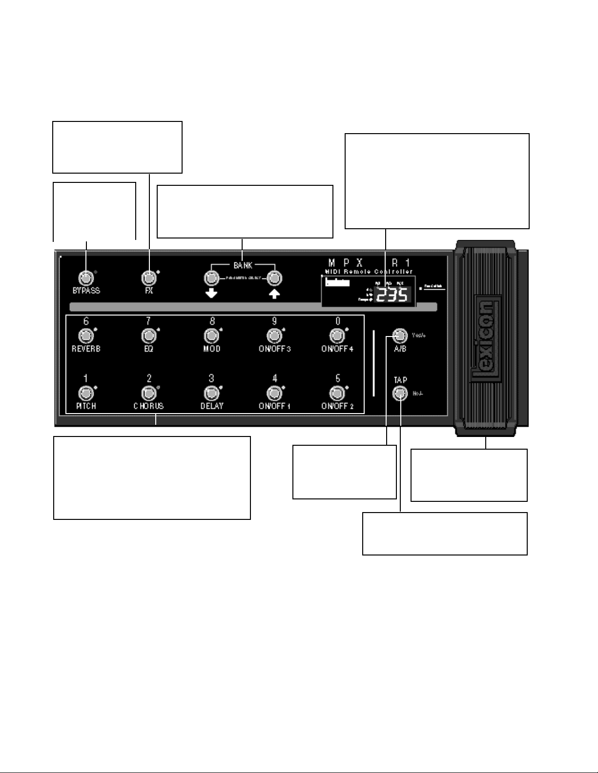
The Front Panel
FX
Toggles between Program and FX
Modes. LED off indicates Program
Mode is active. LED on indicates FX
Mode is active.
Bypass
Assignable switch
sends a MIDI Controller value BYPASS
ON=127; BYPASS
OFF=0.
Bank/Parameter Select
Buttons increment and decrement program banks
(0-25), or select adjustable parameters for editing.
Pressing and holding either button activates fast
scrolling.
LexiconMPX R1 User Guide
Display
FS1, FS2 and FS3 LEDs light to indicate state of
external foot switches.
3-Digit Display indicates ID number of currently
loaded program.
Tempo LED flashes in time with current tempo rate
when Tap is active.
A/B LEDs light to indicate A/B function is active.
Switches (0-9)
Press to complete a Program Change message which
consists of the current Bank number and the switch
number (0-9). In FX mode, switches can be programmed to transmit any MIDI Controller, Clock commands, Relay settings or MIDI Program Change.
Switches 0-9 are used for entering Program Change
selections in Direct Access Mode.
A/B
Assignable switch, when
used with the MPX 1, activates a variable glide between patched parameters.
Tap
When Tempo LED is flashing, sets tempo.
(Press two or more times in rhythm to establish
tempo rate.)
Programmable Pedal
Operates as an assignable MIDI
Continuous Controller. Toe
Switch allows patched effects to
be turned on and off.
1-2
Page 7
Toe Switch
Assignable switch sends MIDI Controller value ON=127; OFF=0.
Product Overview
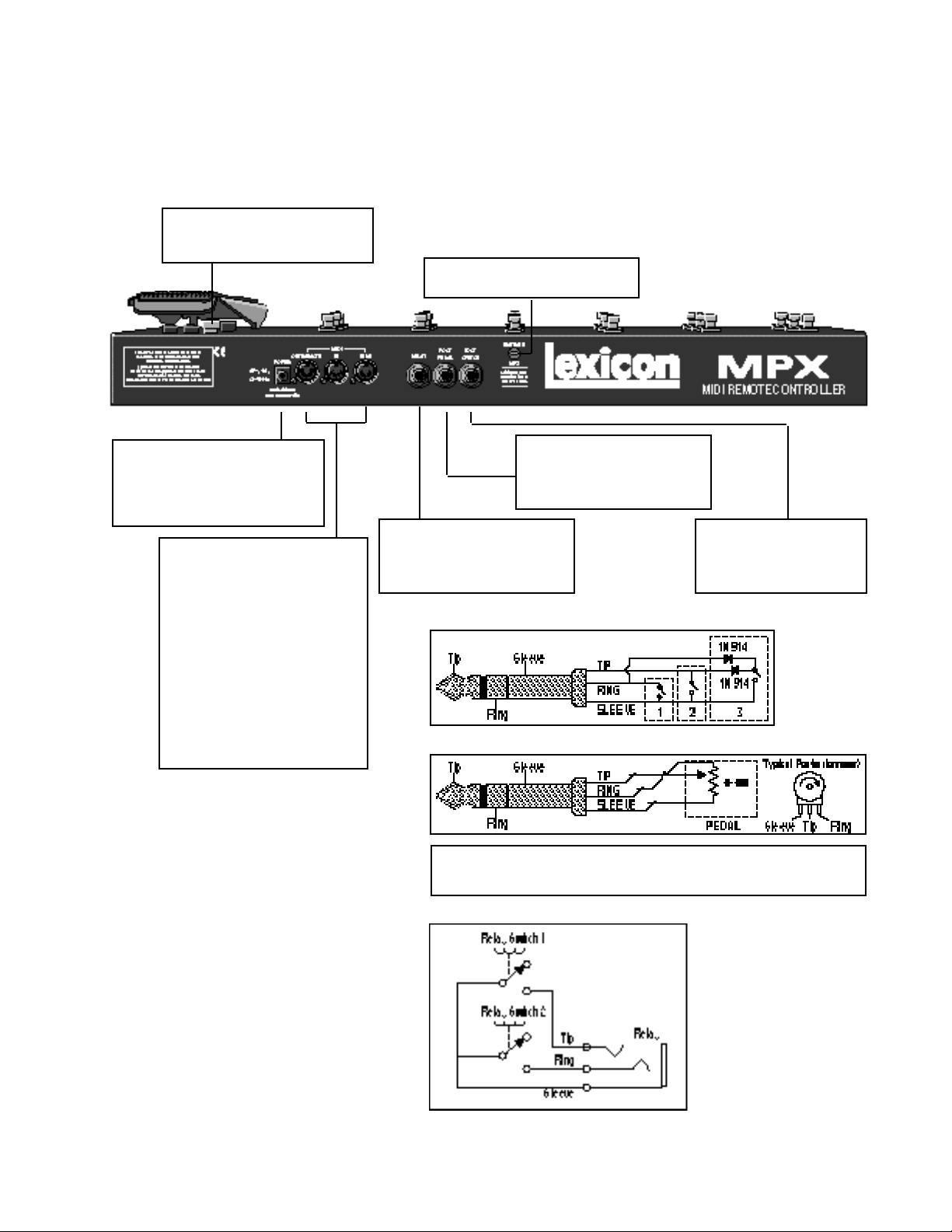
The Rear Panel
Edit/Run
Toggle switch for entering Edit mode.
POWER
Use Lexicon MSA power adapter, or
9 VAC 1 amp equivalent. Jack is
unused when powering the MPX R1
with the 7-pin DIN connector.
MIDI
OUT/REMOTE
5-pin DIN connector for MIDI OUT
or
7-pin DIN connector for MIDI OUT
and bidirectional MIDI remote (for
use with MPX 1).
IN
5-pin DIN connector receives MIDI
data from other equipment.
THRU
5-pin DIN connector passes any
MIDI data received without change.
Foot Pedal
1/4" Tip/Ring/Sleeve phone jack
provided for foot pedal with 10kΩ
to 50kΩ impedance.
Relay
1/4" Tip/Ring/Sleeve phone jack
software selectable as a momentary or latching switch.
Foot Switch
Foot Pedal
For control-voltage input, use a 1/4" stereo plug with Sleeve connected to
ground, Tip connected to the control voltage, and Ring unconnected or shorted
to ground..
Foot Switch
1/4" Tip/Ring/Sleeve phone
jack for as many as three
independent footswitches.
Relay
1-3
Page 8
Installation Notes
LexiconMPX R1 User Guide
Power Requirements
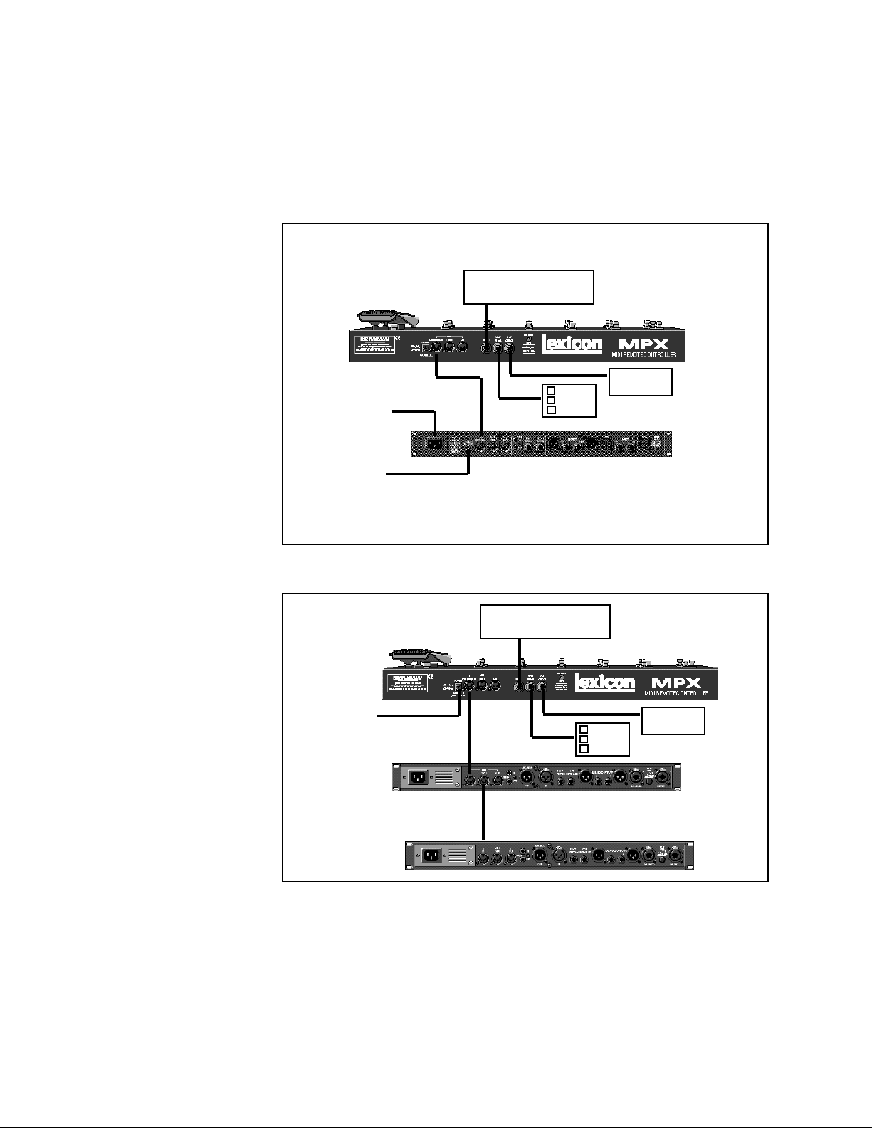
Connecting the MPX R1
to an MPX 1
Use Lexicon MSA power adapter, or 9 VAC 1 amp equivalent.
Relay
(Amp Channel Select)
Foot Pedal
to AC Power
Source
to Lexicon
MSA Adapter
7-pin DIN
Cable
Foot
Switch
Connect a 7-pin DIN cable between the MPX 1 and the MPX R1.
Connect the MPX 1 to the MSA adapter provided with the MPX R1.
Stand-alone
Configuration
to Lexicon
MSA Adapter
MIDI Device 1
MIDI Device 2
5-pin DIN Cable
(Amp Channel Select)
OUT
IN
THRU
5-pin DIN Cable
IN
Relay
Foot Pedal
Foot
Switch
1-4
Page 9

The MPX R1 as a Dedicated MPX 1 Controller
2
When an MPX R1 is connected to an MPX 1, two-way communication is
accomplished via MIDI System Exclusive messages. This allows immediate
response by both units to actions on either front panel.
Using the MPX R1 with the MPX 1 requires V1.10 software to be installed in the
MPX 1. (The software version is shown on the MPX 1 display on power up.) Once
this software is installed in your MPX 1, the following simple procedure will get
you up and running quickly. Note that these instructions assume a general
knowledge of MPX 1 operation. If you are a first-time MPX 1 user, please review
the MPX 1 User Guide for general instruction.
Connect the power adapter provided with the MPX R1 to the MPX 1 REMOTE
POWER input jack and to a wall outlet.
Power up the MPX 1 and connect the 7-pin DIN cable provided with the MPX R1
between the MPX 1 rear panel IN/REMOTE jack and the MPX R1 MIDI OUT/
REMOTE.
The MPX R1 will cycle through a power-up routine, lighting various LEDs, and
then display Con. The MPX 1 will display Remote Connected. These messages indicate that proper bidirectional control has been established.
The MPX R1 as a
Dedicated MPX 1
Controller
MPX 1 Software
Requirements
MPX1 and MPX R1
Connections
When the MPX 1 powers up, it will default to Program Mode. The MPX R1 should
also power up in Program Mode. (FX button LED should be off.) In this mode,
the MPX R1 sends MIDI Program Change and Bank Select messages to load
MPX 1 programs.
These four switches and continuous controller transmit specific MIDI System
Exclusive or Control Change messages regardless of the mode of operation.
In this mode, the state of A/B and the Tempo LED rate will automatically update
to the state of the currently loaded program. For example, if you load a program
set to 100 beats per minute (BPM), the MPX R1 will flash at 100 BPM, just as
the MPX 1 does. If you then load a program set to 120 BPM, the Tempo LED on
the MPX R1 will increase from 100 to 120 BPM when the new program loads.
Pressing and holding the TAP button on the MPX R1 will display the current
tempo in BPM on the R1 display.
Working in
Program Mode
A/B Tap/Tempo, Bypass,
Toe and Pedal
2-1
Page 10
LexiconMPX R1 User Guide
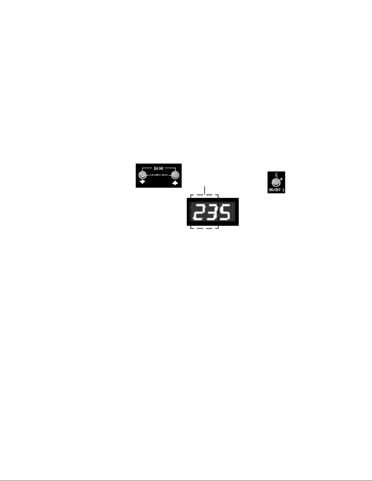
Loading Programs
The first two digits on the display indicate the bank number. The third digit
indicates the program number. The BANK buttons select banks, and switches
0-9 select programs within the displayed bank. Programs are loaded whenever
one of the numbered switches is pressed.
To load a new program within the same bank, press any of the numbered
switches (0-9).
To select a program in a different bank, press the BANK buttons to step to the
bank you want, or hold down either button to scroll through the numbers. The
rightmost digit, which is reserved for program numbers, will turn off during bank
selection. Once you have selected the desired bank, press the numbered switch
to load the program number within that bank.
Use the BANK buttons to select a
bank number. The first two digits
on the display show your selection
— bank 23 in this example.
Press one of the switches numbered 0-9 to select a program within
the selected bank. The third digit
shows our selection — program 5.
Direct Access Mode
You can also enter program numbers directly in Direct Access Mode. Press and
hold the FX button until its LED begins blinking. The display will flash d-A to
indicate that Direct Access Mode is active. Now you can select programs by
directly entering their program numbers. For example, to load MPX 1 Program
135, press 1, then 3, then 5 on the MPX R1.
In this mode, the BANK buttons increment and decrement the program numbers
in consecutive steps.
Press the FX button once to exit to FX Mode, twice to exit to Program Mode.
2-2
Page 11
The MPX R1 as a Dedicated MPX 1 Controller
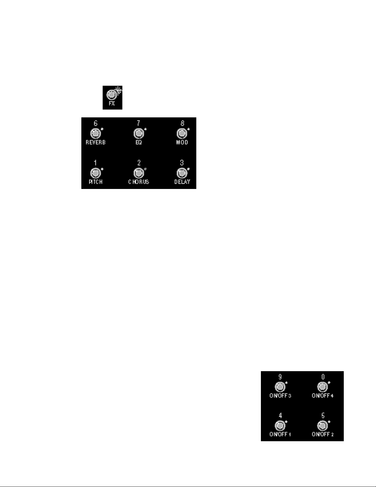
FX Mode allows you to turn on and off any of the active effects in the current
program. To access FX Mode, press the MPX R1 FX button. The LED next to
the button will light to indicate you are in FX Mode.
The FX LED is lit when FX Mode
is active.
Buttons 1, 2, 3, 6, 7 and 8 bring MPX 1 effects (Pitch, Chorus, Delay, Reverb,
EQ and Mod) in and out of bypass. The LED for each button indicates the current
state of the MPX 1 Effect:
Green = MPX 1 Effect on
Red = MPX 1 Effect bypassed, but available
Off = MPX 1 Effect unavailable
FX Mode
As in Program mode, the R1 will update to match the current MPX 1 A/B, Tempo
and Bypass states of the currently loaded program. If you press any of these
controls on the MPX 1, or if you load a new program from the MPX 1, the R1 will
update accordingly.
You can also control the MPX R1 4-state relay in FX mode.
A relay is simply an electronic switch that can tell a circuit (typically an amp's
channel-switching scheme, or reverb and tremolo status) what "state" to go to.
Manufacturers use different schemes, or "logic states" to accomplish similar
tasks, and the MPX R1 can be programmed to satisfy these requirements,
allowing you, for example, to use your MPX R1 as a relacement for your amp's
channel-switching footswitch.
Storing a Relay State
The relay state can be stored with each MIDI Program Change message. To do
this, select the desired MIDI program on the MPX R1 and press the MPX R1 FX
button to enter FX mode
The relay states are assigned to the following buttons as factory defaults.
ON/OFF 1 = Relay state 1
ON/OFF 2 = Relay state 2
ON/OFF 3 = Relay state 3
ON/OFF 4 = Relay state 4
Relay State Programming
2-3
Page 12

LexiconMPX R1 User Guide
Press the button assigned to the desired relay state and hold the button down
for two seconds. The relay state (for example, CH1) will flash three times on the
MPX R1 display to indicate that it has been stored with the program.
Clearing a Relay State
To clear a relay state, press and hold any button not assigned to a relay channel.
Hold this button down for two seconds until – – – flashes three times on the
display to indicate the relay state for that program has been removed.
Removing Relay Settings for All Programs
To reset all of the relay settings to Not Assigned, go to Edit: Program Mode
(Press and hold the rear panel EDIT/RUN switch until Edt appears on the
display.) Use the BANK/Parameter Select buttons to select the Relay Initialize
parameter (rEi). Press Yes/+ to reset all of the relays. Note that the relays stay
in their last state (based on the last physical button press) until a button is
pressed to assign a different state. Briefly press and release the rear panel EDIT/
RUN switch to exit Edit Mode.
Changing Programs
vs. Bypassing Effects
in a Guitar Rig
Using the MPX 1and
the MPX R1 in a Guitar
Amp Effects Loop
When you load a new program, it takes about 100 milliseconds for the MPX 1
to fade out the old program and then fade in the new program. (That’s about a
16th note at 120 BPM.) For most musical situations that’s plenty of time. For
those situations where you really need to “nail” a sound change, you can be
more precise by using the individual effect bypass buttons (in FX Mode) to
instantly turn individual effects on or off.
For example, at the beginning of a tune, load a preset (using Program or Direct
Access Mode) with the effects you want — say, Chorus, Delay and Reverb.
Then, while you're playing, turn the desired effects on and off from FX Mode via
the MPX R1 effect buttons.
First, connect the Effects Loop Send(s) to the MPX 1 Input(s).
If the Effects Loop send has two outputs (L, R):
connect them to the left and right inputs of the MPX 1. On the MPX 1,
press System, select Input Mode and set it to Stereo.
If the Effects Loop has only one output:
connect it to the left input of the MPX 1. On the MPX 1, press System,
select Audio: Input Mode and set it to Mono(L only).
Connect the MPX 1 Output(s) to the amp's Effects Loop Return(s)
2-4
If the Effects Loop has left and right return inputs:
connect them to the left and right outputs of the MPX 1.
If the Effects loop has only a single return input:
connect it to the left output of the MPX 1. (Effects will be richer if both
outputs can be used, but MPX 1 V1.10 presets (100 through 159) have
been optimized for use with only one output connected.
Page 13

The MPX R1 as a Dedicated MPX 1 Controller
If you are using the MPX 1 between a guitar preamp and power amp, refer to the
following section on using a series effect loop.
If you are using the MPX 1 in a dry/wet (3-way) rig, refer to the following section
on using a parallel effects loop.
On the MPX 1:
Press System and make the following adjustments.
• Set Pgm Bypass to Bypass.
• Set Audio Bypass Level to –3dB.
(These settings will ensure that audio will be smooth and uninterrupted during
program changes.)
• Set Bypass Mode to Bypass. (You will hear dry guitar when bypass is on.)
• Set Mix Mode to Program so that each program will load with its own
independent master wet/dry mix value. (The master mix value for each
preset is initially set to work with the MPX 1 in a series effect loop.)
Adjust Mix and Level Values as follows:
• To adjust the overall mix of dry guitar to all effects in any program: press Mix,
select Mstr Mix, and change the value to suite your taste.
• To adjust the mix or level or any of the effects in the program: press Mix,
select the Mix or Level parameter for the desired effect block and adjust. If
you want to make the changes permanent, be sure to store your changes
before loading a new program.
Set Input and Output Levels:
Before powering up the guitar amp, make your audio connections, turn the
MPX 1 Output Level all the way down, and turn your guitar amp master volume
all the way down.
This can be a little tricky, since you must set the MPX 1 output level to match the
level of the preamp with nothing connected in the loop. If the levels are too low,
the amp will not have its usual power and tone. If the levels are too high, you
may overload the power amp – causing unwanted distortion. If your amp has
a loop bypass (like a Mesa/Boogie Mk IV), it’s pretty easy to match the levels.
If not, it will take a little more work. The extra effort is worth it — when the levels
are properly matched, your amp’s tone will be unaffected and you will be able
to use phase shifter, tremolo, wah and other “in-line” effects to their fullest
potential.
• Power up the amp.
• Load MPX 1 Preset 100 Guitar Solo.
• Press Bypass.
• Set the preamp controls to the highest gain settings you’ll be using.
• Turn up the MPX 1 Input Level control so that the 0 dB lights occasionally,
then back it off a bit.
Using the MPX 1 and
the MPX R1 in a
Preamp/Power Amp
Rig or a Dry/Wet
(3-Way) Rig
Using a Series Loop
What kind of effects loop do
you have?
In a series effects loop, the entire
preamp signal passes through the
MPX 1. (If you turn down the MPX 1
Output Level control, no sound
comes out of the amplifier.)
In a parallel loop, the preamp signal
is routed directly to the power amp
and the MPX 1 output is mixed with
it. (If you turn down the MPX 1 Output Level control, you still hear the
guitar at normal level.)
Some amps have a mix control for
the loop. This is sometimes a switch
labeled “50/50” or “mix,”or a mix pot
with a range of 0-100%. These controls allow you to use the loop as
either series or parallel. With a
switch, the 50/50, or mix, position
corresponds to parallel, the other
position corresponds to series. In
the case of a mix pot, 100% corresponds to series and all other positions are parallel. (Halfway or 50% is
a good starting place.)
2-5
Page 14

LexiconMPX R1 User Guide
• Bring up the amp master volume to a point corresponding to a reasonable
listening level. (You won’t hear anything yet.)
• Turn the MPX 1 Output Level control a little more than halfway up (at about
1:00 o’clock). You should now hear sound.
• Compare this level with the level when the MPX 1 is disconnected from the
loop. (This is the tricky part — if your amp has a loop bypass, just bypass the
loop. If it has a loop mix control, set the control to 0%. If not, you may have
to physically disconnect the MPX 1 from the loop.)
• Adjust the MPX 1 Output level control so that the amp's loudness is the same
as when the MPX 1 is not in the loop.
Using a Parallel Loop
On the MPX 1:
Press System and make the following adjustments.
• Set Pgm Bypass to Mute.
• Set System Bypass Mode to Input Mute (delay and reverbs will “ring out”
when Bypass is on) or All Mute (effects are muted when Bypass is on).
• Set Mix Mode to Global, press Mix and set Mstr Mix to 100%.
Adjust Mix and Level Values as follows:
• To adjust the overall mix of dry guitar to all effects in any program, press Mix,
select Mstr Level, and change the value to suite your taste.
• To adjust the mix or level or any of the effects in the program: press Mix,
select the Mix or Level parameter for the desired effect block and adjust. (If
you want to make the changes permanent, be sure to store your changes
before loading a new program.)
Set Input and Output Levels:
Before powering up the guitar amp, make your audio connections, turn the
MPX 1 Output Level all the way down, and turn your guitar amp master volume
all the way down.
[This is pretty simple, as you’re just adding the MPX 1 output to your normal
guitar sound.]
• Power up the amp.
• Load MPX Preset 100, Guitar Solo.
• Set the preamp controls to the highest gain settings you’ll be using.
• Turn up the Input Level control so that the 0 dB lights occasionally when
you're playing your loudest, then back it off a bit.
• Bring up the amp master volume to the desired listening level.
• Turn up the MPX 1 Output Level to the desired effects level.
2-6
Page 15

Using the MPX R1 with Other MIDI Devices
3
The MPX R1 can be used as a stand-alone controller for any standard MIDI
device. When used this way, the MPX R1 transmits MIDI Program Change and
Control Change messages, and controls the built-in 4-state relay.
Connect a 5-pin DIN MIDI cable between the MPX R1 rear panel OUT/REMOTE
jack and MIDI IN jack of the device you wish to control. Connect the Lexicon MSA
Adapter between the POWER jack on the MPX R1 and a wall outlet.
To control multiple devices, connect MIDI cables between the MIDI IN ports of
each new device and the THRU ports of each preceding device.
When the MPX 1 powers up, it will default to Program Mode. The MPX R1 should
also power up in Program Mode. (FX button LED should be off.) In this mode,
the MPX R1 sends MIDI Program Change and Bank Select messages to load
MPX 1 programs.
These four switches transmit information regardless of the mode of operation.
They can be programmed to output an of the sources listed in Edit: FX Mode.
Using the MPX R1
with Other MIDI
Devices
Connections
Working in
Program Mode
A/B, Tap/Tempo, Bypass
and Toe Switch
The first two digits on the display indicate the bank number. The third digit
indicates the program number. The BANK buttons select banks, and switches
0-9 select programs within the displayed bank. Programs are loaded whenever
one of the numbered switches is pressed.
To load a new program within the same bank, press any of the numbered
switches (0-9).
To select a program in a different bank, press the BANK buttons to step to the
bank you want, or hold down either button to scroll through the numbers. The
rightmost digit, which is reserved for program numbers, will turn off during bank
selection. Once you have selected the bank you want, press the numbered
switch to load the desired program within that bank.
Use the BANK buttons to select a
bank number. The first two digits
on the display show your selection
— bank 23 in this example.
Press one of the buttons numbered
0-9 to select a program within the
selected bank. The third digit shows
our selection — program 5.
Loading Programs
3-1
Page 16

LexiconMPX R1 User Guide
Direct Access Mode You can also enter program numbers directly in Direct Access Mode. Press and
hold the FX button until its LED begins blinking. The display will flash d-A to
indicate that Direct Access Mode is active. Now you can select programs by
directly entering their program numbers. For example, to load MPX 1 Program
135, press 1, then 3, then 5 on the R1.
In this mode, the BANK buttons increment and decrement the program numbers
in consecutive steps.
Press the FX button once to exit to FX Mode, twice to exit to Program Mode.
FX Mode
FX Mode allows you to use the MPX R1 buttons numbered 0-9 as MIDI
Controllers. To access FX Mode, press the MPX R1 FX button. The LED next
to the button will light to indicate you are in FX Mode.
The FX LED is lit when FX mode
is active.
Buttons 0-9 can be assigned to any of the following MIDI controllers:
Continuous Controllers 1-31 Start/Stop
Continuous Controllers 33-119 Start
A-B Stop
Tip Continue
Ring Reset
CH1-4 Bypass
3-2
For additional information on all of these sources, refer to Chapter 4 Editing: FX
Parameters.
In FX Mode, transmitted values correspond to the state of the switch and are
indicated by the switch LEDs as follows:
Green = 127 transmitted
Off = 0 transmitted
Note that when used as a stand-alone controller, on and off are the only LED
indicators available. Note also that the LEDs for all of the buttons will remain in
their last toggled states.
Page 17

Using the MPX R1 with Other MIDI Devices
You can also control the MPX R1 4-state relay in FX Mode.
Storing a Relay State
The relay state can be stored with each MIDI Program Change message. To do
this, select the desired MIDI program on the MPX R1 and press the MPX R1 FX
button to enter FX mode.
The relay states are assigned to the following buttons as factory defaults.
ON/OFF 1 = Relay state 1
ON/OFF 2 = Relay state 2
ON/OFF 3 = Relay state 3
ON/OFF 4 = Relay state 4
Press the button assigned to the desired relay state and hold it down for two
seconds. The relay state (for example, CH1) will flash three times on the MPX
R1 display to indicate that it has been stored with the program.
Clearing a Relay State
To clear a relay state, press and hold any button not assigned to a relay channel.
Hold this button down for two seconds until – – – is flashed three times on the
display to indicate the relay state for that program has been removed.
Removing Relay Settings for All Programs
To reset all of the relay settings to Not Assigned, go to Edit: Program Mode and
select the Relay Initialize parameter (rEi). Press Yes/+ to reset all of the relays.
Note that the relays will stay in their last state (based on the last physical button
press) until a button is pressed to assign a different state.
Relay State Programming
3-3
Page 18

LexiconMPX R1 User Guide
3-4
Page 19

Editing
4
MPX R1 edit functions, like basic operations, are divided into two modes by the
front panel Program/FX switch. EDIT: Programs allows you to access system
parameters such as MIDI Channel, Relay state, MIDI Clock, etc. EDIT: FX allows
you to re-assign the MIDI controllers transmitted by the MPX R1 front panel
buttons.
To access EDIT mode, press and hold the MPX R1 rear panel EDIT/RUN switch.
(This recessed switch has been designed for easy access with a guitar pick, pen
point or fingernail.) After three seconds, the MPX R1 display will flash Edt twice,
and the first Program mode parameter will appear as a default. The front panel
A, B and Tempo LEDs will all light to indicate that the unit is in EDIT Mode. (To
exit, press and release the EDIT/RUN switch.)
Parameter Select
Buttons step through available
parameters.
Display
Indicates ID and current value of
selected parameter.
Editing
Press and hold the rear
panel EDIT/RUN switch
to access the MPX R1
Editing functions.
The A, B and Tempo LEDs will all
light to indicate you are in Edit
mode.
Yes/+ and No/–
Adjust parameter value.
In either mode, the front panel BANK/Parameter Select buttons will step through
the list of available parameters. The abbreviated name of each parameter will
flash alternately on the display with the current parameter setting.
Parameter values are adjusted with the front panel YES/+ and NO/– buttons.
Changes made to parameter values are immediate.
The following pages list all of the editable parameters in the MPX R1. An Edit
Summary showing this information in abbreviated form, is provided on an
adhesive chart, to stick onto the bottom of the MPX R1 for easy reference.
4-1
Page 20

Edit Mode
Program Parameters
1
LexiconMPX R1 User Guide
MIDI System Channel Assign Default: 1
Assigns the MIDI transmit channel (1-16) for all buttons (except TOE).
2
3
4
5
6
7
MIDI Internal Pedal Channel Assign Default: 1
Assigns the MIDI transmit channel (1-16) for the onboard foot pedal.
MIDI External Pedal Channel Assign Default: 1
Assigns the MIDI transmit channel (1-16) for the external foot pedal/Analog
controller.
MIDI Toe Channel Assign Default: 1
Assigns the MIDI transmit channel (1-16) for the Toe switch.
External Foot Switch #1 State Select Default: 2
Selects the foot switch state (Latching=1 or Momentary=2) for external foot
switch #1. This allows a momentary foot switch to act like a latching foot switch.
For momentary foot switches, leave this at the default setting (2).
External Foot Switch #2 State Select Default: 2
Selects the foot switch state (Latching=1 or Momentary=2) for external foot
switch #2. This allows amomentary foot switch to act like a latching foot switch.
For momentary foot switches, leave this at the default setting (2).
External Foot Switch #3 State Select Default: 2
Selects the foot switch state (Latching=1 or Momentary=2) for external foot
switch #3. This allows a momentary foot switch to act like a latching foot switch.
For momentary foot switches, leave this at the default setting (2).
10
8
9
MIDI Clock Output On/Off Default: Off
Specifies the source of MIDI clock output. Settings include: Off, On (generate
internally), re (merge from remote in), in (merge from MIDI in).
Program Load mode Default: 3
Determines how program numbers are entered. Two states (indicated below by
a /, indicates a second mode is available by pressing and holding down the FX
button.(In the second mode, the FX light blinks.)
1 = Banks
2 = Direct Access Mode
3 = Banks/Direct Access
4 = Banks/Direct Device
5 = Setup/Direct Access
6 = Setup/Direct Device
Redundant Program Change On/Off Default: On
When set to On (the default), the remote will send a redundant program change
message. (If you select the same program number (0-9) as the program that is
loaded, the remote will send that program change.) When set to Off, the remote
will not send a new program change if the program corresponding to the number
selected is already loaded.
4-2
Page 21

Editing
11
12
13
14
15
16
Program Number Format Select Default: 1
Allows selection of one of two numbering systems: 0-127 (0) or 1-128 (1) for
program numbering. This is a display change only — In MIDI terms, the remote
will always send 0-127 values.
Bank Limit Select Default: 25
When the MPX R1 is not connected to an MPX 1 (which forces 25 banks), a
maximum bank number can be selected here to limit the total number of
accessible banks. The available range is 0-99.
Programs Per Bank Default: 100
Specifies the number of programs in each bank (and thereby tells the MPX R1
when to send a bank change message). The available range is 1-128.
Bank Change Default: 32
Allows selection of the MIDI Controller number to be used as the transmitted
Bank Select message, 0, 32 or 032.
Pedal Curve Select Default: 1
Allows selection of a pedal curve. The available settings are 1-3.
1
Pedal Range Limit Low Default: 0
Sets the controller value (0-127) transmitted when the pedal is in its lowest
position.
2
3
17
18
19
20
21
22
Pedal Range Limit High Default: 127
Sets the controller value (0-127) transmitted when the pedal is in its highest
position.
External Pedal Curve Select Default: 1
Selects a pedal curve (1-3).
External Pedal Range Limit Low Default: 0
Sets the controller value (0-127) transmitted when the pedal is in its lowest
position.
External Pedal Range Limit High Default: 127
Sets the controller value (0-127) transmitted when the pedal is in its highest
position. The default setting is 127.
Pedal Update Mode Default: On
When set to On, the pedal will update the current pedal controller value
immediately. When pedal update is set to Off, the pedal controller value will only
be updated when the pedal is moved.
Internal Pedal Calibration Default: Off
Calibrates the pedal when Yes/+ is selected. Moving the pedal through its entire
range of travel will re-calibrate the range of the pedal (i.e. 0 for minimum value,
127 for maximum value).
4-3
Page 22

LexiconMPX R1 User Guide
23
24
25
26
27
28
29
External Pedal Calibration Default: Off
Calibrates the pedal when Yes/+ is selected. Moving the pedal through its entire
range of travel will re-calibrate the range of the pedal (i.e. 0 for minimum value,
127 for maximum value).
MIDI IN Merge On/Off Default: Off
When set to On, MIDI data received at the MIDI IN jack will be merged to the MIDI
OUT jack.
MIDI THRU Routing Select Default: rE
Allows data from MIDI IN (in) or MIDI remote (rE) to be passed to the THRU port.
Relay Mode Select Default: 1
Allows you to choose how the relay operates. The choices are: 1=latching,
2=momentary normally open, 3=normally closed.
Relay Initialize Default: –
Initializes all of the stored relay states. Choices are Yes or No.
Tempo LED On/Off Default: On
Allows you to turn the Tempo LED On or Off. The LED is normally On.
Device ID Assign Mode Default: 0
Sets a Device ID number (0-126) for the remote.
30
31
32
33
Target ID Assign Mode Default: 0
Set a Target ID number (0-126) for the remote.
MIDI Dump All Default: –
When Yes/+ is pressed, all global settings, system parameters, controller
assignments, relay states and setup information will be dumped via SysEx to the
MIDI OUT port.
MIDI System Dump Default: –
When Yes/+ is pressed, all system parameters will be dumped via SysEx to the
MIDI OUT port.
MIDI Controllers Dump Default: –
When Yes/+ is pressed, all Controller Assignments will be dumped via SysEx
to the MIDI OUT port.
4-4
Page 23

Editing
Note: When the relay state is assigned to a selected button the relay will
automatically change to reflect the current state of the button. Relays with dual
states will default to the first state.
Note: In this mode, pressing any button will transmit the currently assigned
controller. On exiting this mode, all switches will revert to the state they were in
before Edit Mode was entered.
Each of the following buttons can be assigned to the following MIDI controllers:
1-31, 33-119, Start/Stop, Start, Stop, Continue, Reset, tip, ring, CH1, CH2, CH3,
CH4, Off, Bypass, MPX 1 SysEx message for A/B.
1
2
3
4
5
6
7
Bypass Default: CC84
1/Pitch Default: CC77
2/Chorus Default: CC78
3/Delay Default: CC76
4/On/Off 1 Default: CH1
5/On/Off 2 Default: CH2
6/Reverb Default: CC75
Edit Mode
FX Parameters
Pressing any switch assigned to Bypass will disable all buttons, LEDs and
controllers. While this
switch is engaged, the LED
for the button will light, and
the display will flash SuS
(suspended).
10
11
12
13
14
15
16
17
18
19
8
9
7/EQ Default: CC73
8/Mod Default: CC70
9/On/Off 3 Default: CH3
0/On/Off 4 Default: CH4
A/B 1 A/B SysEx
A/B 2 Off
Toe Default: CC83
Internal Pedal Default: CC4
External Pedal Default: CC11
External Footswitch 1 Default: CC80
External Footswitch 2 Default: CC81
External Footswitch 3 Default: CC82
Note that the A/B button can be assigned to simultaneously output two separate
controllers. (It is designed to simultaneously toggle the A/B state of the MPX 1
and the relay for amplifier switching.)
4-5
Page 24

LexiconMPX R1 User Guide
The Relays
Relay Tip
To find out what relay state
scheme your amp uses, connect a 1/4" TRS cable between the MPX R1 and the
amp's rear panel jack for
amp switching. Experiment
be pressing the four MPX R1
relay state switches to determine how the default settings of the MPX R1 affect
your amp's channel-switching scheme. Write down the
results before editing custom
states and setups.
Latching
Two MPX R1 relays can operate in one of three modes: latching, momentary
normally open, and momentary normally closed. The Edit: Program parameter
rel allows you to select one of these options.
The relays are activated by pressing a button assigned to the tip relay, the ring
relay, or to one of four channels. Any button can be assigned to turn the tip or
the ring relay on and off. You can also assign any one of the four channels to any
button. The relay jack accepts a 1/4" TRS connector.
Tip/Ring
Pressing the button assigned to Tip causes the tip relay to change state.
Pressing the button assigned to Ring causes the ring relay to change state.
Momentary,
normally open
Momentary,
normally closed
Channels
Pressing a button assigned to a channel causes the channel to change. The four
channels are defined as shown below:
Channel Tip Relay Ring Relay
1 open open
2 closed open
3 open closed
4 closed closed
Tip/Ring
The tip and ring relays are defined as being normally open. Pressing the button
assigned to the tip or the ring relay closes the relay for 100ms and then opens
it again.
Channels
The “momentary, normally open” state of a channel is Channel 1. Pressing a
channel button causes the relay to momentarily change to that channel’s state
and then change back to Channel 1. (Pressing a button assigned to Channel 1
does nothing.)
Tip/Ring
The tip and ring relays are defined as being normally closed. Pressing the button
assigned to the tip or the ring relay opens the relay for 100ms and then closes
it again.
4-6
Page 25

Channels
The “momentary, normally closed” state of a channel is Channel 4. Pressing a
channel button causes the relay to momentarily change to that channel’s state
and then change back to Channel 4. (Pressing a button assigned to Channel 4
does nothing.)
Editing
Storing a Relay State
The relay state can be stored with each MIDI Program Change message. To do
this, select the desired MIDI program on the MPX R1.
Press the MPX R1 FX button to enter FX mode.
In the MPX R1 the relay states are assigned to the following buttons as factory
defaults.
ON/OFF 1 = Relay state 1
ON/OFF 2 = Relay state 2
ON/OFF 3 = Relay state 3
ON/OFF 4 = Relay state 4
Press the button assigned to the desired relay state and hold the button down
for two seconds. The relay state (for example, CH1) will flash on the MPX R1
display to indicate that it has been stored with the program.
Clearing a Relay State
To clear a relay state, press and hold any button not assigned to a relay channel.
Hold this button down for two seconds until – – – is flashed on the display to
indicate the relay state for that program has been removed.
Relay State Programming
Latching
To assign the relay using tip or ring when the relays are set to latching mode:
Assign the relay state to the desired button. This button will now have two relay
states: State 1 (Green) and State 2 (Off).
Follow the same method for assigning the relay as above. To save the CH1 relay
state, the button must first be put in CH2 relay. Then, when you press and hold
this button it will toggle the to the CH1 relay state.
Momentary
If the relays are set to momentary, normally closed, or to momentary, normally
open, you can store a momentary change on either the tip or the ring relay.
To reset all of the relay settings to Not Assigned, go to Edit: Program mode and
select the Relay Initialize parameter (rEi). Press Yes to reset all of the relays.
Note that the relays will stay in their last state (based on the last physical button
press) until a button is pressed to assign a different state.
Assigning the Relay with
tip and ring
Removing Relay Settings
for all programs
4-7
Page 26

Advanced Applications
Advanced
Applications
5
The MPX R1 is capable of simultaneously outputting multiple MIDI Program
Change messages (called Setups) on as many as eight different MIDI channels.
It can access any MIDI channel and transmit Program Change messages in real
time. Each of these applications is described in this section.
A Setup consists of as many as eight MIDI Program Change messages and one
relay state. The MPX R1 can be programmed with as many as 100 Setups.
To activate Setups or Direct Device Control from Program mode you must select
4, 5 or 6 as a setting for the PL (Program Load) parameter in Edit mode. This
parameter allows you to select one of the following six options as a master mode
for program load behavior:
1 Banks
2 Direct Access
3 Banks/Direct Access
4 Banks/Direct Device
5 Setups/Direct Access
6 Setups/Direct Device
4 Banks/Direct Device uses the standard bank loading scheme on a single
MIDI channel selected in Edit Program Mode. Pressing and holding the FX
button (from either Program or FX Mode) until the LED blinks and d-d flashes
on the MPX R1 display activates Direct Device Control. Pressing FX again
reverts to the standard bank loading scheme.
Transmitting Multiple
Program Changes
on Separate MIDI
Channels
Setups
Activating Setups and Direct
Device Control
5 Setups/Direct Access activates Setup Mode. In this mode, all MIDI Program
Changes are transmitted within Setups. Pressing and holding the FX button
takes you into a version of Direct Access Mode which gives you direct access
only to Setup load. Pressing FX again reverts to Setup Mode.
6 Setups/Direct Device activates Setup Mode. In this mode, all MIDI Program
Changes are transmitted within Setups. Pressing and holding the FX button
(from either Program or FX Mode) until the LED blinks and d-d flashes on the
R1 display activates Direct Device Mode. Pressing FX again reverts to Setup
Mode.
To build a Setup, first set the rear panel EDIT/RUN switch to Edit Mode, then
press and hold the FX button for approximately 2 seconds, until the FX LED
blinks.
The 1/PITCH LED should light up in red and the display should show SEt to
indicate you are in Setup programming mode.
Creating a Setup
5-1
Page 27

LexiconMPX R1 User Guide
The front panel Yes/+ and No/- buttons allow you to select a Setup number (1-
100) for programming. This number is assigned to the 1/PITCH button.
Each of the MPX R1 front panel buttons numbered 2-9 is now available to
memorize Program Change messages. (Button 0/ON/OFF 4 is available for
storing a relay state.)
Select the button you want (2-9) to designate a particular MIDI device.
MPX R1 Button
2/CHORUS Device 1
3/DELAY Device 2
4/ON/OFF 1 Device 3
5/ON/OFF 2 Device 4
6/REVERB Device 5
7/EQ Device 6
8/MOD Device 7
9/ON/OFF 3 Device 8
Setup Parameters
The BANK buttons will now select one of four parameters available to define the
Program Change messages you want to send. The Yes/+ and No/- buttons set
the value for each parameter you select.
PC (Program Change) lets you select a MIDI Program Change message (0-999)
for the selected device. This parameter is specific to each Setup.
Ch (MIDI Channel) lets you select a MIDI Channel (1-16) for communication with
the selected device. This channel will be used for any devices assigned to this
button. This parameter is global for each device.
PPb (Programs Per Bank) lets you specify the number of programs in each bank
(0-999), and therefore, when a bank change message will be transmitted. This
parameter is global for each device.
bC (Bank Change Message) lets you define the Bank Select message (0, 32 or
032) to be transmitted to the selected device. This parameter is global for each
device.
Once these parameters have been set, you can test the device by pressing 2/
CHORUS. This will output all of the MIDI information you have programmed for
the selected device.
To select a relay state to store with the Setup, press 0/ON/OFF 4. This button
is reserved for Setup relay state assignments. When you press the button, the
display should show rEL. on the display)
5-2
Clearing a Setup
The Yes/+ and No/- buttons allow you to select the relay state you want stored
with the Setup.
To clear a Setup, go to Setup Edit mode, and select the number of the Setup you
want to clear, and hold down the BYPASS button. All of the front panel LEDs
except 1/PITCH will turn off, indicating that the Setup has been cleared.
Page 28

Example
1. Press the button for the desired device. The LED will blink green. The first
parameter (Program Change) will be indicated by PC on the display.
2. Use the Yes/+ and No/– buttons to select a Program Change number.
3. Use the BANK buttons to select the next parameter, MIDI Channel.
4. Use the Yes/+ and No/– buttons to select a MIDI Channel.
5. Use the BANK buttons to select the next parameter, Programs Per Bank.
6. Use the Yes/+ and No/– buttons to select the appropriate number for the
connected device.
7. Use the BANK buttons to select the next parameter, Bank Change.
8. Use the Yes/+ and No/– buttons to select the appropriate setting for the
connected device.
Once all of the parameters have been set and you want to test this specific device
Program Change message, press the button you have selected to designate the
device.
Once you press any other device button, this LED will light steady green to
indicate that information is stored at this location.
Advanced Applications
Direct Device Control Mode is similar to Direct Access, except that the Bank
buttons change the MIDI Channel for Program Changes in real time.
In either Program or FX Mode, press and hold the FX button until the FX LED
blinks and d-d is flashed on the display. The display will then alternate the
display of the current MIDI Channel and the last Program Change number
transmitted on that channel.
In this mode you can select programs directly by entering their numbers as
button pushes (as in Direct Access). In addition, the Bank buttons let you access
MIDI Channels 1-16 so that you can transmit a Program Change on any MIDI
Channel in real time.
When you press the FX button again you will revert to the Program Load mode
specified by the PL parameter in Edit Mode with the MIDI Channel reset to the
channel specified by the Ch parameter, or to that specified for the Setup.
Direct Device
Control
5-3
Page 29

LexiconMPX R1 User Guide
Alternative
Connections
2 MIDI cables
and an MSA Adapter
5- pin connection
(1 cable for two-way
MIDI with power from
an adapter)
The following methods allow you to establish two-way MIDI communication
between an MPX R1 and an MPX 1 without using a 7-pin MIDI cable.
Connect a 5-pin MIDI cable between the MPX R1 rear panel OUT/REMOTE jack
and the MPX 1 rear panel MIDI IN/REMOTE jack.
Connect a second 5-pin MIDI cable between the MPX 1 rear panel MIDI OUT
jack and the MPX R1 rear panel MIDI IN jack.
Connect the MSA Adapter to the MPX 1 rear panel POWER jack and plug into
a wall outlet.
If you have a 5-pin MIDI cable which has all five pins wired, connect it between
the MPX R1 rear panel OUT/REMOTE jack and the MPX 1 rear panel MIDI IN/
REMOTE jack.
Connect the MSA Adapter to the MPX 1 rear panel POWER jack and plug into
a wall outlet.
5-4
Page 30

This chapter is intended primarily to help you recognize some common error
states which can be corrected from the MPX R1 front panel, or by simple means
such as cable replacement. Any error states that are not covered here should be
referred to your local dealer or Lexicon Customer Service.
Troubleshooting
6
Troubleshooting
In “low-voltage”, or “brown-out” conditions (less than 40VAC), the MPX R1 will
freeze in its current state. None of the controls will have any effect. When power
returns to a normal level, the unit will reset itself as though it had just been
powered on. If the unit does not reset itself, turn the power OFF, then ON to
resume normal operation.
Temperature extremes may cause the MPX R1 to exhibit unpredictable behavior. If the unit has been subjected to temperatures below 32°F (0°C) or above
95°F (35°C), it should be turned off and allowed to return to normal temperature
before use. The unit may be damaged by exposure to temperatures below -22°F
(-30°C) or above 167°F (75°C), or by exposure to humidity in excess of 95%. If
a unit exposed to such conditions fails to operate after it returns to a normal
operating temperature, contact your local service representative.
The MPX R1 doesn't respond to MIDI Program Changes.
The MPX R1 and connected devices must be set to matching MIDI Channels.
Check the connected device (if an MPX 1, check in the System mode MIDI
menu) as well as in the MPX R1 Edit mode to verify MIDI channel selections.
If connected to an MPX 1:
Make sure that Pgm Change in the MPX 1 System mode MIDI menu is set to
On. See MPX 1 User Guide Chapter 6: MIDI Operation for Program Change
messages which may be ignored by the MPX 1.
Low Voltage
Overheating
Common MIDI
Problems
Check MIDI connections between the units.
6-1
Page 31

MPX R1 User Guide
Lexicon
Adjusting Pedal
Tension
Reinitialization
Reinitialization of the
MPX R1
Reinitialization of the
MPX 1 and the MPX R1
The tension of the foot pedal can be adjusted tighter or looser according to your
preference. Use a #2 Phillips-head screwdriver to adjust the screw located on
the right side of the pedal (as viewed from the top).
On the MPX R1, press the 0 (ON/OFF 4) button while powering up. When all of
the LEDs begin blinking, release the 0 button and press FX to initialize the foot
controller. (Press any other button to cancel the initialization procedure.) This
will reset all of the MPX R1 parameters to the default states listed in Chapter 4.
On the MPX 1, press System and turn the knob to select Initialize. Press the
> button repeatedly to step to the last selection in the Initialize menu: MPX 1/
MPX R1. The Store button will flash, indicating that the MPX 1 is armed to
perform the initialization procedure.
Press System.
Press > repeatedly to
get to the MPX 1/
MPX R1 selection.
Press the flashing Store button
to reinitialize the MPX 1 for use
with the foot controller.
Press Yes to initialize. Press any other button to disarm the initialize function.
6-2
Page 32

Specifications
Dimensions: 23 in x 8 in x 3 in (WHD) (58.42 cm x 20.32 cm x 7.62 cm)
Weight: 9.5 lbs (4.3 kg)
Construction: All metal chassis, switches and expression pedal
External control inputs: 1 1/4" TRS jack supports up to 3 on/off switches
1 1/4" TRS jack for external expression pedal
Internal relays: 1 1/4" TRS jack connected to two internal programmable relays
MIDI: MIDI OUT/REMOTE: 7-pin DIN connector (compatible with standard 5-pin MIDI)
provides phantom power and two-way MIDI communication with the MPX 1
MIDI IN: standard MIDI IN can also be used to merge a second MIDI input stream
when MIDI OUT/REMOTE is connected
MIDI THRU: can be set to pass MIDI from either MIDI IN or REMOTE ports
Power: 9VAC, 1A wall transformer provided
25-foot 7-pin DIN cable for phantom power via MPX 1
Expression pedal: vintage mechanical design, all steel construction, progammable toe switch
Display: 3-digit LED indicates program number and tempo rate
MIDI functions: MIDI bank and program select for up to 300 programs
Switches and pedal(s) can be individually set to transmit any controller. The status
of each MIDI switch is indicated with a green LED.
Tap tempo can be transmitted as MIDI Clock
Relay mapping: Different relay states can be memorized for each of 990 MIDI program numbers
Relays can operate as on/off 1–4 or as two independent on/off switches
MPX 1 functions*: When connected to an MPX 1 via 7-pin cable, R1 LEDs automatically display the
following each time a new program is loaded:
Program number
Master Bypass state
A/B state
Tempo rate
State of each effect block (Pitch, Chorus, EQ, Mod, Delay, Reverb); effect
on=green, effect bypassed=red, effect not active=off)
The state of any active effect can be instantly changed by pressing its associated
switch
Dedicated switches for control of A/B and Tap.
Specifications
7
* MPX 1 requires V1.1 ROM upgrade
7-1
Page 33

MPX R1 User Guide
MIDI Implementation Chart
Lexicon MPX R1
MIDI Remote Controller
Function Transmitted Recognized Remarks
Basic Default 1 X
Channel Changed 1-16 X
Mode Default X X
Messages X X
Altered X
Note X X
Velocity Note ON X X
Note OFF X X
After Keys X X
Touch Channel X X
Pitch Bend X X
Lexicon
Control 1-119 OX X OFF, 1-119, Start/Stop
Change Start, Stop, Continue, Rest,
BYPASS, PITCH, CHORUS, DELAY, Tip, Ring, CH1-4, Off,
ON/OFF1-4, REVERB, EQ, MOD, BYP (0, 32, 032 select
FS 1-3, TOE SWITCH, INTERNAL Banks). All transmit ON=
PEDAL 1-2 127; OFF=0
INTERNAL PEDAL 1 and 2
are continuous controllers
Program 0-127 X Bank change allows
Change True # 1-128 access to programs 0-300
Bank Select O O
System Lexicon OX OX Limited set of SysEx
Exclusive messages
System :Song Pos X X
Common :Song Sel X X
:Tune X X
System :Clock OX X Default set to OFF but
Real Time :Commands OX X can be turned on. Default
tempo=120bpm
Aux :Local ON/OFF X X
Messages :All Notes OFF X X
:Active Sense X X
:Reset All Controllers OX X
Notes
Mode 1: OMNI ON, POLY Mode 2: OMNI ON, MONO O : Yes OX: Selectable
Mode 3: OMNI OFF, POLY Mode 4: OMNI OFF, MONO X : No
7-2
Page 34

Lexicon Inc.
3 Oak Park
Bedford MA 01730-1441 USA
Telephone 781-280-0300
Fax 781-280-0490
www.lexicon.com
Lexicon Part # 070-12712
 Loading...