

Page 1

MC-1
Digital Controller
Service
Manual
Page 2
MC-1 Service Manual
Precautions
Save these instructions for later use.
Follow all instructions and warnings marked on the unit.
Always use with the correct line voltage. Refer to the manufacturers operating instructions for power requirements. Be advised that
different operating voltages may require the use of a different line cord and/or attachment plug.
Do not install the unit in an unventilated rack, or directly above heat producing equipment such as power amplifiers. Observe the
maximum ambient operating temperature listed in the product specification.
Slots and openings on the case are provided for ventilation; to ensure reliable operation and prevent it from overheating, these
openings must not be blocked or covered. Never push objects of any kind through any of the ventilation slots. Never spill a liquid of
any kind on the unit.
This product is equipped with a 3-wire grounding type plug. This is a safety feature and should not be defeated.
Never attach audio power amplifier outputs directly to any of the unit’s connectors.
To prevent shock or fire hazard, do not expose the unit to rain or moisture, or operate it where it will be exposed to water.
Do not attempt to operate the unit if it has been dropped, damaged, exposed to liquids, or if it exhibits a distinct change in performance
indicating the need for service.
This unit should only be opened by qualified service personnel. Removing covers will expose you to hazardous voltages.
This triangle, which appears on your component, alerts you to the presence of uninsulated, dangerous voltage inside the
enclosure… voltage that may be sufficient to constitute a risk of shock.
CAUTION
RISK OF ELECTRIC SHOCK
DO NOT OPEN
This triangle, which appears on your component, alerts you to important operating and maintenance Instructions in this
accompanying literature.
Notice
This equipment generates and uses radio frequency energy and if not installed and used properly, that is, in strict accordance with the
manufacturer's instructions, may cause interference to radio and television reception. It has been type tested and found to comply with
the limits for a Class B computing device in accordance with the specifications of Part 15 of FCC Rules, which are designated to
provide reasonable protection against such interference in a residential installation. However, there is no guarantee that interference
will not occur in a particular installation. If this equipment does cause interference to radio or television reception, which can be
determined by turning the equipment OFF and ON, the user is encouraged to try to correct the interference by one or more of the
following measures:
If necessary, the user should consult the dealer or an experienced radio/television technician for additional suggestions. The user may
find the following booklet prepared by the Federal Communications Commission helpful:
This booklet is available from the U.S. Government Printing Office, Washington, DC 20402, Stock No. 004-000-00345-4.
Le présent appareil numérique n'émet pas de bruits radioélectriques dépassant les limites applicables aux appareils numériques de Ia
class B prescrites dans le Règlement sur le brouillage radioélectrique édicté par le ministère des Communications du Canada.
Reorient the receiving antenna
Relocate the computer with respect to the receiver
Move the computer away from the receiver
Plug the computer into a different outlet so that the computer and receiver are on different branch circuits.
“How to identify and Resolve Radio/TV Interference Problems.
Copyright © 1999-2002 Lexicon, Inc.
All Rights Reserved
Lexicon Inc. ● 3 Oak Park ● Bedford, MA 01730-1441 ● Tel (781) 280-0300 ● Customer Service Fax (781) 280-0499
Lexicon Part # 070-14397 Rev 0
Printed in the United States of America
Page 3

Safety Suggestions
Lexicon
Read Instructions Read all safety and operating
instructions before operating the unit.
Retain Instructions Keep the safety and
operating instructions for future reference.
Heed Warnings Adhere to all warnings on the
unit and in the operating instructions.
Follow Instructions Follow operating and use
instructions.
Heat Keep the unit away from heat sources such
as radiators, heat registers, stoves, etc., including
amplifiers which produce heat.
Ventilation Make sure that the location or
position of the unit does not interfere with its
proper ventilation. For example, the unit should
not be situated on a bed, sofa, rug, or similar
surface that may block the ventilation openings;
or, placed in a cabinet which impedes the flow of
air through the ventilation openings.
Wall or Ceiling Mounting Do not mount the unit
to a wall or ceiling except as recommended by
the manufacturer.
Power Sources Connect the unit only to a power
supply of the type described in the operating
instructions, or as marked on the unit.
Grounding or Polarization* Take precautions
not to defeat the grounding or polarization of the
unit’s power cord.
*Not applicable in Canada.
Power Cord Protection Route power supply
cords so that they are not likely to be walked on
or pinched by items placed on or against them,
paying particular attention to cords at plugs,
convenience receptacles, and the point at which
they exit from the unit.
Nonuse Periods Unplug the power cord of the
unit from the outlet when the unit is to be left
unused for a long period of time.
Water and Moisture Do not use the unit near
water — for example, near a sink, in a wet
basement, near a swimming pool, near an open
window, etc.
Object and liquid entry Do not allow objects to
fall or liquids to be spilled into the enclosure
through openings.
Cleaning The unit should be cleaned only as
recommended by the manufacturer.
Servicing Do not attempt any service beyond
that described in the operating instructions. Refer
all other service needs to qualified service
personnel.
Damage requiring service The unit should be
serviced by qualified service personnel when:
the power supply cord or the plug has been
damaged, objects have fallen, or liquid has been
spilled into the unit, the unit has been exposed to
rain, the unit does not appear to operate normally
or exhibits a marked change in performance, the
unit has been dropped, or the enclosure
damaged.
Page 4

MC-1 Service Manual
Page 5

Lexicon
Table of Contents
Chapter 1 Reference Documents, Required Equipment............................. 1-1
Reference Documents............................................................................................................................. 1-1
Required Equipment................................................................................................................................ 1-1
Tools .................................................................................................................................................... 1-1
Test Equipment.................................................................................................................................... 1-1
Chapter 2 General Information ................................................................... 2-3
Periodic Maintenance .............................................................................................................................. 2-3
Ordering Parts ......................................................................................................................................... 2-3
Returning Units to Lexicon for Service .................................................................................................... 2-3
Chapter 3 Specifications............................................................................. 3-1
Chapter 4 Performance Verification............................................................ 4-1
Initial Inspection:...................................................................................................................................... 4-1
Functional Tests: ..................................................................................................................................... 4-1
Analog Input Test................................................................................................................................. 4-1
Audio Performance Verification: .............................................................................................................. 4-2
Input to Record Outputs Test............................................................................................................... 4-2
Input to Zone 2 Output Test ................................................................................................................. 4-3
Main Audio Output Test ....................................................................................................................... 4-4
Digital Input to Analog Output Tests .................................................................................................... 4-4
Video Input / Output Tests....................................................................................................................... 4-5
Composite Input to Composite Monitor / Records (1 and 2) Outputs Tests......................................... 4-5
S-Video Input to S-Video Monitor / Records (1 and 2) Outputs Tests.................................................. 4-6
Expansion Port Digital Input to Analog Output Test ................................................................................ 4-6
Setup.................................................................................................................................................... 4-7
Test...................................................................................................................................................... 4-7
Digital Output Test................................................................................................................................... 4-7
Setup.................................................................................................................................................... 4-7
Test...................................................................................................................................................... 4-8
Lexicon Audio Precision ATE Summary .............................................................................................. 4-9
Chapter 5 Troubleshooting ......................................................................... 5-1
V4 Release Notes.................................................................................................................................... 5-1
V1.00 bug descriptions: ....................................................................................................................... 5-1
Diagnostics .............................................................................................................................................. 5-1
Diagnostic Reporting............................................................................................................................ 5-1
VFD Display: ........................................................................................................................................ 5-2
Front Panel LEDs:................................................................................................................................ 5-2
Serial Debug Pot:................................................................................................................................. 5-2
Error Log: ............................................................................................................................................. 5-2
Diagnostic Control/Interface:................................................................................................................ 5-3
Power On Diagnostics: ........................................................................................................................ 5-3
Extended Diagnostics .......................................................................................................................... 5-6
Pre-Burn in Tests ................................................................................................................................. 5-7
Functional Suite ................................................................................................................................... 5-7
Burn-In Loop ........................................................................................................................................ 5-9
Troubleshooting Problems..................................................................................................................... 5-10
Initial Inspection ................................................................................................................................. 5-11
User Interface Problems: ................................................................................................................... 5-12
Audio Problems.................................................................................................................................. 5-12
Video Problems.................................................................................................................................. 5-13
Power Supply..................................................................................................................................... 5-14
Video Subcarrier Calibration .............................................................................................................. 5-15
Restoring Defaults ............................................................................................................................. 5-16
Page 6

MC-1 Service Manual
Chapter 6 Parts List .................................................................................... 6-1
MC1 MAIN BOARD ASSEMBLY..............................................................................................................6-1
MC1 DIGITAL INPUT BOARD ASSEMBLY .............................................................................................6-4
MC1 RCA EXPANSION BOARD ASSEMBLY .........................................................................................6-4
MC1 VIDEO BOARD ASSEMBLY............................................................................................................6-4
MC1 RCA BOARD ASSEMBLY ...............................................................................................................6-6
MC1 ENCODER BOARD ASSEMBLY.....................................................................................................6-6
MC1 IR BOARD ASSEMBLY ...................................................................................................................6-6
MC1 POWER SWITCH BOARD ASSEMBLY ..........................................................................................6-6
DTS BOARD ASSEMBLY ........................................................................................................................6-6
MC1 CHASSIS/MECHANICAL ................................................................................................................6-7
MC1 PACKAGING/MISCELLANEOUS ....................................................................................................6-8
MC1 POWER CORDS .............................................................................................................................6-8
MC1 RACK MOUNT OPTION..................................................................................................................6-8
Chapter 7 Drawings .................................................................................... 7-1
Schematics...............................................................................................................................................7-1
Drawings ..................................................................................................................................................7-1
Page 7

Lexicon
Chapter 1 Refe rence Documents, Required Equipment
Reference Documents
MC-1 Owner's Manual - Lexicon P/N 070-13278
MC-1 Quick Reference Guide - Lexicon P/N 070-13279, latest revision
Required Equipment
Tools
The following is a minimum suggested technician's tool kit required for performing disassembly, assembly
and repairs:
• Clean, antistatic, well lit work area.
• (1) #1 Phillips tips screwdriver
• (1) Nut driver starter size #2
• (1) 7/16" Nut drive
• Solder: 63/37 - Tin/Lead Alloy composition, low residue, no-clean solder.
• Magnification glasses and lamps
• SMT Soldering / Desoldering bench-top repair station
Test Equipment
The following is a minimum suggested equipment list required to perform the proof of performance tests.
• A high quality A/V source playback system
• Compact Disc player or other source with 44.1kHz sample rate, digital coax and optical
outputs.
• DVD Player or other source with 48kHz kHz sample rate, digital coax and optical outputs.
• 2 full range speakers
• DVD player with both Composite and S-Video outputs
• Color TV Monitor with both Composite and S-Video inputs
• Cables: (dependent on your signal source)
• 1 single-ended, shielded 75-ohm digital audio cable with RCA plugs on both ends for
connecting the outputs of the Disc player to the digital Coax 1 input of the MC-1.
• 2 single-ended, shielded audio cables with RCA plugs on both ends for connecting the
outputs of the Disc player to the inputs of the MC-1.
• 2 single-ended shielded audio cables with RCA plugs on one end and appropriate
connectors on the other end to the input of the stereo amplifier.
• Audio input Y cable with 2 RCA plugs on the Y end and an appropriate connector to the
Low Distortion Oscillator
• 1 single-ended, shielded audio cable with a RCA connector on one end and an appropriate
connector on the other for connection to the low distortion oscillator.
• 1 single-ended shielded audio cable with RCA connector on one end and appropriate
connector on the other end to connect to the input connector of the THD+N distortion
analyzer.
• 2 single-ended, shielded 75 ohm video RCA style cables
• 2 single-ended, shielded 75 ohm video S-Video style cables
• Low distortion analog oscillator with audio bandpass or 20k - 30khz Low Pass Filter;
Single-ended 600 ohm or less output < .005% THD
• Analog distortion analyzer and level meter
• 100 MHz oscilloscope or better
• Digital distortion analyzer & digital function generator (e.g. Stanford Research Systems
Model DS360 or Audio Precision System 1 with DSP Option /System 2 - optional).
• MC-1 Remote Control, Lexicon P/N - 750-13221
1-1
Page 8

MC-1 Service Manual
• DMM (Digital Multi-Meter) - 3 1/2 digit with +/- 0.5% accuracy.
• (1) variable AC supply, 2 amp minimum.
• (1) digital multimeter (DMM) 3.5 digital, 0.5%, or better accuracy.
• (1) frequency counter with a 7 digit accuracy
Page 9

Lexicon
Chapter 2 Gene ral Information
Periodic Maintenance
Under normal conditions the MC-1 system requires minimal maintenance. Use a soft, lint-free cloth slightly
dampened with warm water and mild detergent to clean the exterior surfaces of the connector box.
Do not use alcohol, benzene or acetone-based cleaners or any strong commercial cleaners. Avoid
using abrasive materials such as steel wool or metal polish. It the unit is exposed to a dusty environment, a
vacuum or low-pressure blower may be used to remove dust from the unit's exterior.
Ordering Parts
When ordering parts, identify each part by type, price and Lexicon Part Number. Replacement parts can be
ordered from:
LEXICON, INC.
3 Oak Park
Bedford, MA 01730-1441
Telephone: 781-280-0300; Fax: 781-280-0499; email: csupport@lexicon.com
ATTN: Customer Service
Returning Units to Lexicon for Service
Before returning a unit for warranty or non-warranty service, consult with Lexicon Customer
Service to determine the extent of the problem and to obtain Return Authorization. No equipment
will be accepted without Return Authorization from Lexicon.
If Lexicon recommends that a MC-1 be returned for repair and you choose to return the unit to Lexicon for
service, Lexicon assumes no responsibility for the unit in shipment from the customer to the factory,
whether the unit is in or out of warranty. All shipments must be well packed (using the original packing
materials if possible), properly insured and consigned, prepaid, to a reliable shipping agent.
When returning a unit for service, please include the following information:
• Name
• Company Name
• Street Address
• City, State, Zip Code, Country
• Telephone number (including area code and country code where applicable)
• Serial Number of the unit
• Description of the problem
• Preferred method of return shipment
• Return Authorization #, on both the inside and outside of the package
Please enclose a brief note describing any conversations with Lexicon personnel (indicate the name of the
person at Lexicon) and give the name and telephone daytime number of the person directly responsible for
maintaining the unit.
Do no include accessories such as manuals, audio cables, footswitches, etc. with the unit, unless
specifically requested to do so by Lexicon Customer Service personnel.
2-3
Page 10

Page 11

Chapter 3 Spec ifications
Inputs
Audio: 8 stereo (RCA) pairs
Video: 8 composite (RCA), 8 S-video
Digital: 8: 5 coaxial (RCA), 3 optical (TosLink), conforms to IEC-958, S/PDIF standards;
3 Expansion Ports for 960kHz, 24-bit PCM digital audio
Outputs
Audio: 8 main (RCA): Left, Center, Right, L&R Sides, Subwoofer
3 stereo pairs: 2 Record, 1 Zone 2
Video: 3 composite (RCA), 3 S-video: 1 Monitor, 2 Record
Audio
A/D Conversion: 24-bit Delta-Sigma
D/A Conversion: 24-bit Delta-Sigma
Frequency Response: 10 Hz - 20kHz, +0.2dB, -0,2dB, referenced to 1 kHz
THD+Noise: Less than 0.005% @ 1 kHz, maximum output level
Dynamic Range: 105dB minimum, 22kHz bandwidth, referenced to 1 kHz @ 60dB below
maximum output level
Signal-to-Noise Ratio: 105dB minimum, 22kHz bandwidth, referenced to 1 kHz @ maximum
output level
Input Level: 2 Vrms for maximum output (with Input Gain=0dB); 200mVrms for Dolby
Level
Input Impedance: 100 kΩ in parallel with 150pF
Output Level: 6 Vrms (System Volume = +12dB)
Output Imepdance: 100Ω in parallel with 150pF
Lexicon
Video
NTSC M, PAL and SECAM-compatible
Output Level: 1.0 V peak-to-peak
Impedance: 75Ω
Input Return Loss: 40dB
Differential Gain: <0.5%
Differential Phase: <0.5°
Frequency Response: 10 Hz to 10 MHz ±0.1dB
Bandwidth: >25 MHz
K Factor: <0.3%
Gain: ±0.15dB
Signal/Noise Ratio: >70dB
Power Requirements
90-250 VAC, 50-60 Hx, 35 Watts (universal input); IEC detachable power cord
Dimensions
17.3"W x 11.5"D x 3.6"H (440 x 292 x 92mm)
Rack Mounted: 19.0"W x 11.5"D x 3.5"H (483 x 292 x 89mm)
Weight: 10.8 lbs. (4.9kg)
Environment
Operating Temperature: 32° to 95°F (0° to 35°C)
Storage Temperature: -22° to 167°F (-30° to 75°C)
Relative Humidity: 95% max without condensation
Remote Control
Hand-held, battery-powered infrared remote control unit, uses 2 AA batteries
Specifications subject to change without notice.
3-1
Page 12

Page 13

Lexicon
Chapter 4 Perfo rmance Verification
This section describes a quick verification of the operation of the MC-1 and the integrity of its analog and
digital audio signal paths.
Initial Inspection:
1. Check each front panel switch for smooth mechanical operation and verify that the display
acknowledges its functions.
2. Verify that all of the front panel LEDs light at power up.
3. Check all the buttons on the remote and verify that the display is responding to all the remote
commands.
Functional Tests:
Analog Input Test
Setup
1. Connect the oscillator outputs to the Left and Right inputs of the VCR input on the rear panel of the MC1
2. Connect the MC-1 Left and Right Front audio outputs to the amplifier Left and Right inputs and the
outputs of the amplifier to a pair of speakers.
3. Put the MC-1 into its Extended Diagnostics mode by applying power to the MC-1 while pressing and
holding down both the front panel REC/ZONE2 and EFFECT ▼ buttons until Extended Diagnostics
appears on the display.
4. Press the TAPE button on the remote to select Audio Test.
5. Press the VCR button on the remote. AUDIO Test 13 will appear in the display which confirms the VCR
input is connected to all 8 audio outputs of the MC-1.
6. Slowly increase the volume on the amplifier to a comfortable listening level for the speaker .
7. Sweep the oscillator from 20Hz to 20kHZ you should hear clean audio coming from both speakers.
8. Power off the amplifier and move the cables from the Front Left / Right outputs to the Center left and
Subwoofer right outputs. Repeat the oscillator sweep again checking for clean audio from the speakers.
Repeat this step for the remaining outputs on the MC-1.
9. In order to test the remaining MC-1 inputs, power off the amplifier and the MC-1. Reconnect the MC-1
Front Left / Right outputs to the amplifier.
10. Move the cables from the MC-1 VCR Left / Right inputs to the DVD Left / Right inputs.
11. Press the DVD button on the remote. The display will read AUDIO Test 12, which will confirm the DVD
input is connected to all 8 audio outputs of the MC-1.
12. Repeat steps 6 to 8 above for the DVD input. When done repeat the test for the remaining inputs.
13. The following ID#s will confirm which inputs you have selected for test.
VCR: 13 DVD: 12 V-DISC: 11 TV: 10
AUX: 0F CD: 0E TUNER: 0D TAPE: 0C
14. Press and hold the Shift button on the remote then press the Done button once. This will place the MC1 at the top of the Extended Diagnostics Menu. Releasing the Shift button and then pressing the DONE
button one more time will then cause the MC-1 to exit the Extended Diagnostics and drop into normal
operation.
Listening Test
1. Power up the MC-1 in normal operating mode.
2. Connect a music source to the Left / Right VCR audio inputs of the MC-1.
3. Press "PARTY" on the remote control.
4-1
Page 14

MC-1 Service Manual
4. Connect the MC-1 Left /Right Front audio outputs to the amplifier Left / Right inputs and the outputs of
the amplifier to a pair of speakers.
5. Slowly increase the volume level on the amplifier to a comfortable listening level and verify that the
audio is free from noise, distortion, or any other audio irregularities.
6. Repeat for all other Main outputs.
Mute Test
For proper Mute testing, the MC-1 must be set to the Full Mute Setting.
1. Set the MC-1 up as described in the listening test above.
2. On the MC-1 remote, press SELECT to access the Main Menu.
3. Press Menu ▼ until the display reads: Main Menu/Setup.
4. Press SELECT to enter the top of the Setup Menu.
5. Press Menu ▼ until the Outputs Level Menu is displayed, then press SELECT.
6. Press Menu ▼ until the MUTE LEVEL -30dB is displayed.
7. Press SELECT to display: System Mute Assign/ -30dB.
8. Press Menu ▼ until the Full Mute is displayed.
9. Press SELECT.
10. Press DONE four times to place the MC-1 back into normal operation.
11. With Audio running through the MC-1 press the MUTE button on the remote and verify that the audio
signal disappears.
12. Press the MUTE button again and verify that the audio signal returns.
13. Repeat steps 1 to 7 above and reset the MUTE LEVEL to –30dB.
Audio Performance Verification:
Performing these tests assures that the audio signal paths in the MC-1 are functional and that the MC-1
meets published specifications. These tests verify the functionality of all main audio paths. The performance
of the A/D and D/A conversion circuitry are checked through gain, frequency response, THD+N, and S/N
Ratio tests.
Input to Record Outputs Test
Setup
1. Attach the audio input cable between the Low Distortion Oscillator and the MC-1 Left VCR input.
2. Attach the audio output cable between the MC-1 Left Record output and the input of the Distortion
Analyzer.
3. Put the MC-1 into Extended Diagnostics mode by powering up the MC-1 while pressing and holding
down both the front panel REC/ZONE2 and EFFECT buttons until Extended Diagnostics appears on
the display.
4. Press the TAPE button on the remote. The display will read AUDIO Test.
5. Press and hold the Shift button on the remote, then press the Off button. The # 99 will then be
displayed next to AUDIO Test.
6. Press and hold the RECORD button on the remote, then press the VCR button. The # 53 will then be
displayed confirming the VCR input is now set to the RECORD outputs.
Tests
1. Apply a 1kHz signal @ +12dB (+4 Vrms) to the input channel.
2. Set the scale on the Distortion Analyzer to measure +12dBV (+ 4Vrms ) signal level.
3. Turn all filters off on the Analyzer.
4. Verify that the output level from the MC-1 is +12dBV (+4Vrms) +0.2/-0.3dBV.
5. Adjust the scale on the Distortion Analyzer to measure 0.005% THD+N and turn on the 30kHz low pass
or audio bandpass filter.
6. Verify that the THD+N measured is less than 0.005%.
7. Set the scale on the Distortion Analyzer to measure +12dBV (+ 4Vrms) signal level.
4-2
Page 15

Lexicon
8. Use the output level from Step 4 above for a 0dB reference to check frequency response.
9. Turn the filter off. Next sweep the oscillator frequency from 10Hz to 20kHz.
10. Verify that the signal level is within +0.2/-0.3dB of reference level over the frequency band.
11. Set the scale on the Distortion Analyzer to measure –90dBr signal level with the filter on. Turn off the
oscillator to the MC-1 and verify a noise level measurement less than -100dBr.
12. Swap the cables from the Left VCR input to the Right and the Left RECORD output to the Right.
13. Repeat steps 1 to 11 above for the Right RECORD output.
14. To test the remaining inputs of the MC-1 to the RECORD outputs each path must be set with the
remote control. Press and hold the RECORD button, then press one of the analog input buttons to set
up the next input to RECORD output path. Below are the verification #’s next to their button titles that
indicate the path has been enabled. After a new input is selected the procedure above needs to be
repeated to test the path.
RECORD, VCR: 53 RECORED, DVD: 52 RECORD, V-DISC: 51 RECORD, TV: 50
RECORD, AUX: 4F RECORD, CD: 4E RECORD, TUNER: 4D RECORD, TAPE: 4C
Input to Zone 2 Output Test
Setup
1. Attach the audio input cable between the Low Distortion Oscillator and the MC-1 Left VCR input.
2. Attach the audio output cable between the MC-1 Zone 2 output and the input of the Distortion
Analyzer.
3. Put the MC-1 into Extended Diagnostics mode by powering up the MC-1 while pressing and holding
down both the front panel REC/ZONE2 and EFFECT buttons until Extended Diagnostics appears on
the display.
4. Press the TAPE button on the remote. The display will read AUDIO Test.
5. Press and hold the Shift button on the remote, then press the Off button. The #99 will then be displayed
next to AUDIO Test.
6. Press and hold the RECORD button on the remote then the VCR button. The # 53 will then be
displayed. This confirms the VCR input is now set to the ZONE 2 outputs.
Tests
1. Apply a 1kHz signal @ +12dB (+4 Vrms) to the input channel.
2. Set the scale on the Distortion Analyzer to measure +12dBV (+ 4Vrms ) signal level.
3. Turn all filters off on the Analyzer.
4. Verify that the output level from the MC-1 is +12dBV ( +4Vrms ) +0.2/-0.3dBV.
5. Adjust the scale on the Distortion Analyzer to measure 0.005% THD+N and turn on the 30kHz low
pass or audio bandpass filter.
6. Verify that the THD+N measured is less than 0.005%
7. Use the output level from Step 4 above for a 0dB reference to check frequency response.
8. Set the scale on the Distortion Analyzer to measure +12dBV (+ 4Vrms) signal level.
9. Turn the filter off and sweep the oscillator frequency from 10Hz to 20kHz.
10. Verify that the signal level is within +0.2/-0.3dB of reference level over the frequency band.
11. Set the scale on the Distortion Analyzer to measure –100dBr signal level with the filter on. Turn off the
oscillator to the MC-1 and verify a noise level measurement less than -105dBr.
12. Swap the cables from the Left VCR input to the Right and the Left ZONE 2 output to the Right.
13. Repeat steps 1 to 11 above for the Right ZONE 2 output.
14. To test the remaining inputs of the MC-1 to the ZONE 2 outputs, each path must be set with the
remote control. Press and hold the ZONE 2 button, then press one of the analog input buttons to set
up the next input to ZONE 2 output path. Below are the verification #’s next to their button titles that
indicate the path has been enabled. After a new input is selected the procedure above needs to be
repeated to test the path.
4-3
Page 16

MC-1 Service Manual
RECORD, VCR: 53 RECORED, DVD: 52 RECORD, V-DISC: 51 RECORD, TV: 50
RECORD, AUX: 4F RECORD, CD: 4E RECORD, TUNER: 4D RECORD, TAPE: 4C
Main Audio Output Test
Setup
1. Attach the audio input cable between the Low Distortion Oscillator and the MC-1 Left VCR input.
2. Attach the audio output cable between the MC-1 Left Front output and the input of the Distortion
Analyzer.
3. Put the MC-1 into Extended Diagnostics mode by powering up the MC-1 while pressing and holding
down both the front panel REC/ZONE2 and EFFECT buttons until Extended Diagnostics appears on
the display.
4. Press the TAPE button on the remote. The display will read AUDIO Test.
5. Press and hold the Shift button on the remote, then press the On button. The #98 will then be displayed
next to AUDIO Test. This indicates that the VCR input to Plain Analog outputs path has been enabled.
Tests
1. Apply a 1kHz signal @ +12dB (+4 Vrms) to the input channel.
2. Set the scale on the Distortion Analyzer to measure +12dBV (+ 4Vrms ) signal level.
3. Turn all filters off on the Analyzer.
4. Verify that the output level from the MC-1 is +12dBV (+4Vrms) +0.2/-0.3dBV.
5. Adjust the scale on the Distortion Analyzer to measure 0.005% THD+N and turn on the 30kHz low pass
or audio bandpass filter.
6. Verify that the THD+N measured is less than 0.005%
7. Set the scale on the Distortion Analyzer to measure +12dBV (+ 4Vrms) signal level.
8. Use the output level from Step 4 above for a 0dB reference to check frequency response.
9. Turn the filter off. Next sweep the oscillator frequency from 10Hz to 20kHz.
10. Verify that the signal level is within +0.2/-0.3dB of reference level over the frequency band.
11. Set the scale on the Distortion Analyzer to measure –100dBr signal level with the filter on. Turn off the
oscillator to the MC-1 and verify a noise level measurement less than -105dBr.
12. Swap the Left Front output cable to the Right Front output.
13. Repeat steps 1 to 11 above.
14. Test the remaining Main outputs of the MC-1 being sure to repeat steps 1 to 11 for each.
Digital Input to Analog Output Tests
This test verifies that all 8 digital inputs to an analog output of the MC-1 are functioning properly. It is
important that all previous tests from this section be preformed prior to this test.
Setup
1. Connect the coaxial digital source to the MC-1 Coax 1 input.
2. Connect the MC-1’s Left and Right Front audio outputs to the amplifier Left and Right inputs, and turn
down the volume level control on the amplifier.
3. Place the MC-1 into Extended Diagnostics mode by applying power to the MC-1 while pressing and
holding down both the REC/ZONE2 and EFFECT buttons on the front panel until Extended Diagnostics
appears on the display.
4. Press the TAPE button on the remote to select the AUDIO Test.
5. Press and hold down the SHIFT button, then press the CD button to select a digital input source. The
display should read: AUDIO Test 8E.
6. Press the Dolby Digital button on the remote to select Coax 1 digital input for testing. The #20 will be
displayed to indicate the Digital Coax 1 to output test path has been set.
4-4
Page 17
Lexicon
Tests
1. With the audio source playing, slowly increase the volume level on the amplifier to a comfortable
listening level and verify that the outputs are free from noise, distortion or any other audio anomalies.
2. To test the remaining 7 digital inputs, the following button pushes must be done to make a complete
digital input to analog output test path. Each selection below shows the digital input the button that
activates and the number that will appear in the display to confirm the path is set.
THX = Coax 2, # 21 Logic 7 = Coax 3, # 22 DTS = Coax 4, # 23 2 CH = Coax 5, # 24
Party = Optical 1,# 25 TV M = Optical 2, # 26 Music = Optical 3, # 27
3. Once all of the digital inputs are tested, press and hold the SHIFT button, then press DONE. This will exit
the Extended Diagnostics tests.
Video Input / Output Tests
These tests will verify that all 16 video inputs (8 composite / 8 S-Video inputs) pass video to the 6 video
outputs (3 composite / 3 S-Video).
Composite Input to Composite Monitor / Records (1 and 2) Outputs Tests
Setup
1. Connect the Composite video output from the DVD player to the MC-1 VCR Composite video input.
2. Connect the Composite video Monitor output of the MC-1 to the video display's Monitor Composite
video input.
3. Place the MC-1 into Extended Diagnostics mode by applying power to the MC-1 while pressing and
holding down both the REC/ZONE2 and EFFECT buttons on the front panel until Extended Diagnostics
appears n the display.
4. Press the TV button on the remote to select the VIDEO Test. Press and hold Shift, then press the ON
button. This will set the MC-1 to except an external video source for testing.
5. Turn on the video source and monitor.
Tests
1. To test the VCR Composite input to Video Monitor Composite output path, press the VCR button on the
remote. The # 13 will appear next to the Video Test message on the display, this indicates the path has
been set.
2. Press Play on the video source.
3. Verify a clear, undistorted picture appears on the monitor.
4. Pause the video source.
5. Move the Composite video input from the VCR to the DVD video input. Press the DVD button on the
remote. The # 12 will appear confirming this video path is set. Repeat steps 2-4 above.
6. To test the remaining Composite inputs move the video cable to the next Composite input and press
the corresponding button to set up the video path. Below are the buttons and code #’s for each video
input.
VCR: 13 DVD: 12 V-DISC: 11 TV: 10
AUX: 0F CD: 0E TUNER: 0D TAPE: 0C
7. To test the Record Composite output port of the MC-1, switch the composite cable from the Composite
Monitor output jack to the Composite Record output jack.
8. Select the MC-1's 8 composite inputs for the Composite Record output from the remote according to
the table below. Example: Pressing and holding the Record button on the remote, then pressing the
VCR button selects the VCR composite input for the Record composite output. The # 53 will appear in
the display to confirm this. Below are the button combinations and code #’s for each video input.
4-5
Page 18

MC-1 Service Manual
RecVCR: 53 RecDVD: 52 RecV-DISC: 51 RecTV: 50
RecAUX: 4F RecCD: 4E RecTUNER: 4D RecTAPE: 4C
S-Video Input to S-Video Monitor / Records (1 and 2) Outputs Tests
Setup
1. Connect the S-Video output from the DVD player to the MC-1 VCR S-Video input.
2. Connect the S-Video Monitor output of the MC-1 to the video display's Monitor S-Video input.
3. Place the MC-1 into Extended Diagnostics mode by applying power to the MC-1 while pressing and
holding down both the REC/ZONE2 and EFFECT buttons on the front panel until Extended Diagnostics
appears on the display
4. Press the TV button on the remote to select the VIDEO Test. Press and hold Shift, then press the ON
button. This will set the MC-1 to except an external video source for testing.
5. Turn on the video source and monitor.
Test
1. To test the VCR S-Video input to Video Record S-Video output path, press the Dolby button on the
remote. The # 20 will appear next to the Video Test message on the display. This indicates the path
has been set.
2. Press Play on the video source.
3. Verify a clear, undistorted picture appears on the monitor.
4. Pause the video source.
5. Move the S-Video input cable from the VCR input to the DVD input. Press the DVD button. The # 21 will
appear confirming this video path is set.
6. Repeat steps 2-4.
7. To test the remaining S-Video inputs, move the video cable to the next S-Video input and press the
corresponding buttons to set up the video paths. Below are the buttons and code #’s for each video
input.
Dolby Digital: 20 (VCR
input)
DTS: 23 (TV input) 2 CH: 24 (AUX
TV M: 26 (TUNER input) MUSIC: 27 (TAPE
8. To test the Record S-Video output port of the MC-1, switch the S-Video cable from the S-Video Monitor
output jack to the S-Video Record output jack.
9. Select the MC-1's 8 S-Video inputs for the S-Video Record output from the remote according to the
table below. Example: Pressing and holding the Shift button on the remote then pressing the VCR
button selects the VCR S-Video input for the Record S-Video output. The # 93 will appear in the display
to confirm this. Below are the button combinations and code #’s for each video input.
ShiftVCR: 93 ShiftDVD: 92 ShiftV-DISC: 91 ShiftTV: 90
ShiftAUX: 8F ShiftCD: 8E ShiftTUNER: 8D ShiftTAPE: 8C
THX: 21 (DVD input) Logic 7: 22 (V-DISC
input)
PARTY: 25 (CD input)
input)
input)
Expansion Port Digital Input to Analog Output Test
This test will confirm that the MC-1’s 3 expansion ports (A, B, and C) will pass audio.
The test does not require the MC-1 to be in Extended Diagnostics. It is preformed in normal running mode.
4-6
Page 19

Lexicon
If the MC-1 is currently in Extended Diagnostics, turn the unit off and on to bring it back to normal running
mode.
This test will confirm the MC-1 can pass a 44.1, 48, and 96kHz digital signal to the Analog outputs.
Setup
1. Connect the output of the DVD player with the Single end of the Y-ed RCA cable.
2. Connect one RCA connector of the Y-ed cable to the (A) Expansion Port on the back of the MC-1.
3. Connect the MC-1’s Left and Right Front audio outputs to the amplifier Left and Right inputs, and turn
down the volume level control on the amplifier.
4. Connect the Left and Right outputs of the amplifier to full range speakers.
5. After the MC-1 has powered up, press and hold down the Shift button then press the 2 Channel button.
Test
1. With the audio source playing, slowly increase the volume level on the amplifier to a comfortable
listening level and verify that the outputs are free from noise, distortion, or any other anomalies.
2. The display will read the following and will indicate the frequency it is passing as well as the volume
level:
EXP PORT ## K VOL
DIRECT BYPASS -30dB
3. Pause the audio, then connect the other RCA connector on the Y-ed end to the MC-1 to the (B)
Expansion Port. Keep the (A) RCA connected to MC-1 connected to the unit.
4. Move the Front Left / Right output cables to the Center / Sub RCA connectors.
5. Press play on the audio source and again, as in step one, listen for any anomalies.
6. Pause the audio once more. Disconnect the RCA connection to the (B) Expansion Port and connect it
to the (C) Expansion Port.
7. Move the Center / Sub connectors to the Side Left / Right outputs.
8. Press play on the audio source and again, as in step one, listen for any anomalies.
9. Pause the audio once more.
10. Move the Side Left / Right output cables to the Rear Left / Right outputs.
11. Press play on the audio source and again, as in step one, listen for any anomalies.
12. The above procedure must be repeated for the remaining sample frequencies not tested.
Digital Output Test
This will confirm that the MC-1 will pass a 44.1 or 48 kHz digital signal for the S/PDIF output connector on
the back of the MC-1.
Setup
1. Connect the digital output of the CD player to the digital input Coax 1 on the back of the MC-1.
2. Connect the S/PDIF output of the MC-1 to the digital input of the DAT machine.
3. Connect the Analog Left / Right outputs of the DAT to the Analog inputs of the stereo amplifier.
4. Connect the Left / Right analog output of the amplifier to a pair of speakers.
5. Put the MC-1 into Extended Diagnostics mode by powering up the MC-1 while pressing and holding
down both the front panel REC/ZONE2 and EFFECT buttons until Extended Diagnostics appears on
the display.
6. Press the TAPE button on the remote. The display will read AUDIO Test.
7. Press and hold the Shift button on the remote, then press the Off button. The # 99 will then be
displayed next to AUDIO Test,
4-7
Page 20

MC-1 Service Manual
Test
1. With the audio source playing, slowly increase the volume level on the amplifier to a comfortable
listening level and verify that the outputs are free from noise, distortion, or any other anomalies.
4-8
Page 21

Lexicon
Lexicon Audio Precision ATE Summary
This chart represents a summary of test Audio Precision test equipment settings and parameters used by
Lexicon Manufacturing in production testing of all MC-1 product. This is provided as a reference and
supplement to bench test settings found in the proof of performance in this manual.
All Tests = 25 Ohm, Unbal, Float
All Tests = Filter OFF, Imp. 100K, 44.1kHz Sample Rate (Except 48K Tests)
Test Name Left Right Freq (Hz) Level Measure Reading Upper Lower Band Commands
DIGGAN44 -1dBFS -1dBFS 997 Vrms AMPLITUDE 7.1 7.66 6.54 <10>500K COAX1#1 ShiftCD DOLBY
DIG997 -1dBFS -1dBFS 997 % THD+N 0.003 0.005 0.0002 <10-22K COAX1#1 ShiftCD DOLBY
DIG100 -1dBFS -1dBFS 100 % THD+N 0.003 0.005 0.0002 <10>500K COAX1#1 ShiftCD DOLBY
JITTER44 -1dBFS -1dBFS 10,000 % THD+N 0.003 0.008 0.0002 <10-22K COAX1#1 ShiftCD DOLBY
DIGD_R -60dBFS -60dBFS 997 dBr AMPLITUDE -103 -99.94 -120 <10-22K COAX1#1 ShiftCD DOLBY
DIGFREQ -1dBFS -1dBFS 10-20K dBr AMPLITUDE 0 0.26 -0.36 <10-22K COAX1#1 ShiftCD DOLBY
DIGGAN44 -1dBFS -1dBFS 997 Vrms AMPLITUDE 7.1 7.66 6.54 <10>500K COAX2#1 ShiftCD THX
DIG997 -1dBFS -1dBFS 997 % THD+N 0.003 0.005 0.0002 <10-22K COAX2#1 ShiftCD THX
DIG100 -1dBFS -1dBFS 100 % THD+N 0.003 0.005 0.0002 <10>500K COAX2#1 ShiftCD THX
JITTER44 -1dBFS -1dBFS 10,000 % THD+N 0.003 0.008 0.0002 <10-22K COAX2#1 ShiftCD THX
DIGD_R -60dBFS -60dBFS 997 dBr AMPLITUDE -103 -99.94 -120 <10-22K COAX2#1 ShiftCD THX
DIGFREQ -1dBFS -1dBFS 10-20K dBr AMPLITUDE 0 0.26 -0.36 <10-22K COAX2#1 ShiftCD THX
DIGGAN44 -1dBFS -1dBFS 997 Vrms AMPLITUDE 7.1 7.66 6.54 <10>500K COAX3#1 ShiftCD L7
DIG997 -1dBFS -1dBFS 997 % THD+N 0.003 0.005 0.0002 <10-22K COAX3#1 ShiftCD L7
DIG100 -1dBFS -1dBFS 100 % THD+N 0.003 0.005 0.0002 <10>500K COAX3#1 ShiftCD L7
JITTER44 -1dBFS -1dBFS 10,000 % THD+N 0.003 0.008 0.0002 <10-22K COAX3#1 ShiftCD L7
DIGD_R -60dBFS -60dBFS 997 dBr AMPLITUDE -103 -99.94 -120 <10-22K COAX3#1 ShiftCD L7
DIGFREQ -1dBFS -1dBFS 10-20K dBr AMPLITUDE 0 0.26 -0.36 <10-22K COAX3#1 ShiftCD L7
DIGGAN44 -1dBFS -1dBFS 997 Vrms AMPLITUDE 7.1 7.66 6.54 <10>500K COAX4#1 ShiftCD DTS
DIG997 -1dBFS -1dBFS 997 % THD+N 0.003 0.005 0.0002 <10-22K COAX4#1 ShiftCD DTS
DIG100 -1dBFS -1dBFS 100 % THD+N 0.003 0.005 0.0002 <10>500K COAX4#1 ShiftCD DTS
JITTER44 -1dBFS -1dBFS 10,000 % THD+N 0.003 0.008 0.0002 <10-22K COAX4#1 ShiftCD DTS
DIGD_R -60dBFS -60dBFS 997 dBr AMPLITUDE -103 -99.94 -120 <10-22K COAX4#1 ShiftCD DTS
DIGFREQ -1dBFS -1dBFS 10-20K dBr AMPLITUDE 0 0.26 -0.36 <10-22K COAX4#1 ShiftCD DTS
DIGGAN44 -1dBFS -1dBFS 997 Vrms AMPLITUDE 7.1 7.66 6.54 <10>500K COAX5#1 ShiftCD 2 CH
DIG997 -1dBFS -1dBFS 997 % THD+N 0.003 0.005 0.0002 <10-22K COAX5#1 ShiftCD 2 CH
DIG100 -1dBFS -1dBFS 100 % THD+N 0.003 0.005 0.0002 <10>500K COAX5#1 ShiftCD 2 CH
JITTER44 -1dBFS -1dBFS 10,000 % THD+N 0.003 0.008 0.0002 <10-22K COAX5#1 ShiftCD 2 CH
DIGD_R -60dBFS -60dBFS 997 dBr AMPLITUDE -103 -99.94 -120 <10-22K COAX5#1 ShiftCD 2 CH
DIGFREQ -1dBFS -1dBFS 10-20K dBr AMPLITUDE 0 0.26 -0.36 <10-22K COAX5#1 ShiftCD 2 CH
DIGGAN44 -1dBFS -1dBFS 997 Vrms AMPLITUDE 7.1 7.66 6.54 <10>500K OPTIC1#1 ShiftCD PARTY
DIG997 -1dBFS -1dBFS 997 % THD+N 0.003 0.005 0.0002 <10-22K OPTIC1#1 ShiftCD PARTY
DIG100 -1dBFS -1dBFS 100 % THD+N 0.003 0.005 0.0002 <10>500K OPTIC1#1 ShiftCD PARTY
JITTER44 -1dBFS -1dBFS 10,000 % THD+N 0.003 0.008 0.0002 <10-22K OPTIC1#1 ShiftCD PARTY
DIGD_R -60dBFS -60dBFS 997 dBr AMPLITUDE -103 -99.94 -120 <10-22K OPTIC1#1 ShiftCD PARTY
DIGFREQ -1dBFS -1dBFS 10-20K dBr AMPLITUDE 0 0.26 -0.36 <10-22K OPTIC1#1 ShiftCD PARTY
DIGGAN44 -1dBFS -1dBFS 997 Vrms AMPLITUDE 7.1 7.66 6.54 <10>500K OPTIC2#1 ShiftCD TVM
DIG997 -1dBFS -1dBFS 997 % THD+N 0.003 0.005 0.0002 <10-22K OPTIC2#1 ShiftCD TVM
DIG100 -1dBFS -1dBFS 100 % THD+N 0.003 0.005 0.0002 <10>500K OPTIC2#1 ShiftCD TVM
JITTER44 -1dBFS -1dBFS 10,000 % THD+N 0.003 0.008 0.0002 <10-22K OPTIC2#1 ShiftCD TVM
DIGD_R -60dBFS -60dBFS 997 dBr AMPLITUDE -103 -99.94 -120 <10-22K OPTIC2#1 ShiftCD TVM
DIGFREQ -1dBFS -1dBFS 10-20K dBr AMPLITUDE 0 0.26 -0.44 <10-22K OPTIC2#1 ShiftCD TVM
DIGGAN44 -1dBFS -1dBFS 997 Vrms AMPLITUDE 7.1 7.66 6.54 <10>500K OPTIC3#1 ShiftCD MUSIC
DIG997 -1dBFS -1dBFS 997 % THD+N 0.003 0.005 0.0002 <10-22K OPTIC3#1 ShiftCD MUSIC
DIG100 -1dBFS -1dBFS 100 % THD+N 0.003 0.005 0.0002 <10>500K OPTIC2#1 ShiftCD MUSIC
JITTER44 -1dBFS -1dBFS 10,000 % THD+N 0.003 0.008 0.0002 <10-22K OPTIC3#1 ShiftCD MUSIC
DIGD_R -60dBFS -60dBFS 997 dBr AMPLITUDE -103 -99.94 -120 <10-22K OPTIC3#1 ShiftCD MUSIC
DIGFREQ -1dBFS -1dBFS 10-20K dBr AMPLITUDE 0 0.26 -0.44 <10-22K OPTIC3#1 ShiftCD MUSIC
DIGREC -1dBFS -1dBFS 997 Vrms AMPLITUDE 2Vrms 2.3 1.69 <10-22K COAX1#1 ShiftCD DOLBY
CLKRNG44 -1dBFS -1dBFS 997 % THD+N 0.003 0.008 0.002 <10-22K COAX1#1 ShiftCD DOLBY
NOTE: GAIN 48, JITTER 48, AND CLKRNG48 use a 48kHz Sample
Rate
DIGGAN48 -1dBFS -1dBFS 997 Vrms AMPLITUDE 7.1 7.66 6.54 <10>500K COAX1#1 ShiftAUX DOLBY
JITTER48 -1dBFS -1dBFS 10,000 % THD+N 0.003 0.008 0.0002 <10-22K COAX1#1 ShiftAUX DOLBY
DIGGAN48 -1dBFS -1dBFS 997 Vrms AMPLITUDE 7.1 7.66 6.54 <10>500K COAX2#1 ShiftAUX THX
JITTER48 -1dBFS -1dBFS 10,000 % THD+N 0.003 0.008 0.0002 <10-22K COAX2#1 ShiftAUX THX
DIGGAN48 -1dBFS -1dBFS 997 Vrms AMPLITUDE 7.1 7.66 6.54 <10>500K COAX3#1 ShiftAUX L7
JITTER48 -1dBFS -1dBFS 10,000 % THD+N 0.003 0.008 0.0002 <10-22K COAX3#1 ShiftAUX L7
DIGGAN48 -1dBFS -1dBFS 997 Vrms AMPLITUDE 7.1 7.66 6.54 <10>500K COAX4#1 ShiftAUX DTS
JITTER48 -1dBFS -1dBFS 10,000 % THD+N 0.003 0.008 0.0002 <10-22K COAX4#1 ShiftAUX DTS
DIGGAN48 -1dBFS -1dBFS 997 Vrms AMPLITUDE 7.1 7.66 6.54 <10>500K COAX5#1 ShiftAUX 2 CH
JITTER48 -1dBFS -1dBFS 10,000 % THD+N 0.003 0.008 0.0002 <10-22K COAX5#1 ShiftAUX 2 CH
DIGGAN48 -1dBFS -1dBFS 997 Vrms AMPLITUDE 7.1 7.66 6.54 <10>500K OPTIC1#1 ShiftAUX PARTY
Typical Remote
4-9
Page 22

MC-1 Service Manual
JITTER48 -1dBFS -1dBFS 10,000 % THD+N 0.003 0.008 0.0002 <10-22K OPTIC1#1 ShiftAUX PARTY
DIGGAN48 -1dBFS -1dBFS 997 Vrms AMPLITUDE 7.1 7.66 6.54 <10>500K OPTIC2#1 ShiftAUX TVM
JITTER48 -1dBFS -1dBFS 10,000 % THD+N 0.003 0.008 0.0002 <10-22K OPTIC2#1 ShiftAUX TVM
DIGGAN48 -1dBFS -1dBFS 997 Vrms AMPLITUDE 7.1 7.66 6.54 <10>500K OPTIC3#1 ShiftAUX MUSIC
JITTER48 -1dBFS -1dBFS 10,000 % THD+N 0.003 0.008 0.0002 <10-22K OPTIC3#1 ShiftAUX MUSIC
4-10
Page 23

Lexicon
Chapter 5 Trou bleshooting
Check the Lexicon web site for the latest software and information:
http://www.lexicon.com
The Lexicon Home Theater Products downloads page:
http://www.lexicon.com/downloads/ht_index.html
The Lexicon Support Knowledgebase:
http://www.lexicon.com/kbase/index.asp
V4 Release Notes
The MC1 software has been updated to V4 which includes Surround EX. This is a list of the bugs that were
fixed in V1.1 which have carried forward to V4.
V1.00 bug descriptions:
1. Decorrelation does not work in AC3 THX 5.
2. Right rear output sometimes mutes in DTS THX 5.1.
3. Video signal bleedthrough when in Standby with SECAM Format selected.
4. Bass levels are too loud in Music Surround, Music Logic and TV Matrix effects.
5. The Bass Enhance parameter clicks when turning it on or off and may overload in the right front channel.
6. The Side Rolloff and Rear Rolloff parameters do not work in the Music Surround effect. They have been
replaced by one Surround Rolloff parameter.
7. The Center Bass Split crossover frequency points are too high, causing low frequency information to leak
into the Front Left and Right speakers in AC3 effects.
8. The Auto Azimuth parameter is not working in Logic7 and TV Matrix effects.
9. The level meters are not working correctly in AC3 and DTS effects.
Diagnostics
There are two sets of MC-1 Diagnostics: Power On Diagnostics, and Extended Diagnostics. The Power On
Diagnostics are automatically executed each time power is applied to the MC-1 via the rear panel power
switch. Extended Diagnostics are not automatically executed, but can be invoked by the user for specific
purposes. Extended Diagnostics include additional tests to verify front panel controls, inferred
communications, and audio and video performances, as well as those used to troubleshoot the MC-1.
In normal use, the MC-1 is left connected to AC power and its operation is controlled by the front panel
ON/STANDBY button or by the remote control. When controlled this way, Power On Diagnostics are not
executed.
Diagnostic Reporting
All diagnostics functionality is reported to the front panel Vacuum Fluorescent Display, and to the front
panels LEDs. These identify the test being executed, and pass and failure information. The LEDs are
utilized to report diagnostic status in the event that the VFD is not functioning. More information is available
on the diagnostic reporting operation of the VFD and the front panel LEDs in the VFD display, and front
panel LEDs section.
In the event of diagnostic failure, additional information, such as data sent, data received, address location
etc, is listed in an error log can be found in the Error Log.
Diagnostic status and data is also available to a external PC or terminal, via the Serial Port Debug Port
(RS232) on the rear panel of the MC-1.
5-1
Page 24

MC-1 Service Manual
VFD Display:
The front panel VFD display is the primary source of information during diagnostics. The exact display
information will depend on the test or tests being executed. When an individual diagnostic test is executed,
the VFD will display the name of that test. Groups of tests, such as during power on diagnostics or burn in
loops, will have a generic message on the top line of the VFD, e.g. DIAGNOSTIC TESTS, when the tests
are being executed. Any failure message will display an E followed by a number that indicates which test
failed.
Front Panel LEDs:
The test number associated with any particular test will also be displayed on the front panel LEDs. The
LEDs will be used in binary format with the MUTE LED as the LSB and the red TAPE LED as the MSB.
Running test number 1 would illuminate the MUTE LED only with all the others off. Running test number 2
would illuminate the BYPASS LED only with all others off. Running test number 3 would illuminate the
MUTE and BYPASS LEDs together with all others off, etc.
If a failure occurs, the red VCR LED is illuminated to indicate the test failure, and the LEDs indicating which
test was running when the failure occurred would also be illuminated. The diagnostics will attempt to
continuously execute the failed test, a test loop, to keep the signal lines active as an aid in debugging the
failure. Due to the MC-1 design of scanning the front panel LEDs, the diagnostics running the test loop, and
reporting the failure once during the loop, the LEDs on time is reduced. This results in the LEDs flickering,
and is normal operation.
Serial Debug Pot:
The Serial Debug Port is available to provide diagnostic status to be viewed on an external PC through one
of the serial ports on the PC. On the rear of the MC-1 is a 5-pin din connector. Pin 4 of the connector is
wired to the serial debug port. Using a terminal or a PC running a terminal program at 19.2kbs, the progress
of the diagnostics can be monitored and test failure information is reported. Also, the error log can be
dumped to the serial debug port, while in EXTENDED DIAGNOSTICS, via the remote SHIFT/ON key
combination.
Error Log:
An error log, or ring buffer, containing a log of the last 20, 13h, failures is available. If the error quantity
exceeds 20, additional error messages will be stored at the first location in the buffer (FIFO). The error log
is stored in the non- volatile section of SRAM.
Every failure stored in the error log has 6 parts:
#NN E## tXX aYYYYYY
wZZZZZZ rQQQQQQ
1. #NN: Error Log Number: the error log location number, in hexadecimal. It goes from 00 to 13. Turning
the VOLUME knob clockwise allows one to scroll through all 20 error log locations.
2. E##: Failure Number: the E stands for error and the 2-digit number after the E indicates which test
failed.
3. tXX: Failure Type
01 = Address Failure. During an address test the data sent compared to the data retrieved does not
match.
02 = Data Failure. During a data test the data sent does not match the data retrieved.
03 = Timeout Failure. The device being sent data does not return any ready or data transfers
acknowledge.
5-2
Page 25

Lexicon
04 = Counter Failure.
05 = Non-Volatile Data Failure. The data stored in non-volatile memory during the Pre-Burn In test does
not match the value tested during the Burn-in Loop.
4. aYYYYYY: Failing address location. The address, in hexadecimal, where the failure occurred.
5. wZZZZZZ: Value Written. The target value, in hexadecimal, which was written to the address where the
failure occurred.
6. rQQQQQQ: Value Read. The actual value, in hexadecimal, which was read from the address where the
failure occurred.
In addition, the error log can be viewed on an external PC or terminal via the serial debug port. The error
log is sent to the serial debug port when the MUTE F.P. button is used to select the error log or using the
SHIFT/ON infrared command if you are in the EXTENDED DIAGNOSTICS. The IR command can be sent
to the MC-1 via the handheld remote or sent to the MC-1 using IRTX.
Diagnostic Control/Interface:
Various combinations of button pushes are used to control diagnostics activity. During Power On
Diagnostics, three options are available: skipping the Power On Diagnostics, entering Extended
Diagnostics, or proceeding to the next test. Each of these options is described below.
Skip Power On Diagnostics:
Simultaneously pressing the VCR and TAPE buttons will skip the Power On Diagnostics routine and put the
unit into operating mode. The MC-1 periodically checks for this button combination during Power On
Diagnostics and will attempt to skip any remaining tests when this command is detected.
Enter Extended Diagnostics:
When power is applied to the MC-1, the VFD and the front panel LEDs are lit for 3 seconds. To enter
extended Diagnostics, press and hold down on the front panel the REC/ZONE2 and EFFECT buttons until
the end of the 3-second interval. The VFD will indicate Extended Diagnostics. Alternatively, during the
interval, press and hold SELECT on the remote until Extended Diagnostics is displayed.
Pressing and holding EFFECT and MUTE following the failure of any test other than the Z80 CPU test will
activate Extended Diagnostics. After a failure occurs the unit will attempt to display the failed test number,
and will execute a loop of the failing test.
Proceed to the Next Diagnostics Test:
Pressing and holding both the BYPASS and REC/ZONE 2 buttons after a failure occurs will cause the MC1 to attempt to execute the next power on diagnostic test. Normally if a failure occurs the MC-1 attempts to
enter a test loop to keep the signal lines active as an aid in debugging the failure. At the end of each
successive loop, the diagnostics will check to see if the BYPASS and REC/ZONE 2 buttons are being held.
Depending on the length of the test, the amount of time required to hold down the buttons in will vary.
Power On Diagnostics:
Power On Diagnostics verify the functionality of the basic MC-1 hardware. They do not completely test all
hardware, nor can they fully diagnose a failure. Power On Diagnostics take approximately 20 seconds to
complete. When the unit is powered on, an attempt is made to illuminate the VFD and front panel LEDs for
approximately three seconds. As soon as the Z80, EPROM, SRAM, and VFD are determined to be
functional, the VFD will show.
DIAGNOSTIC TESTS
………………………………………
5-3
Page 26

MC-1 Service Manual
The dots decrement in number from both sides simultaneously, as the rest of the power on diagnostic tests
are completed. This keeps a user informed as to the functioning of the MC-1.
The power on diagnostic tests are intended to verify basic hardware functionality of the MC-1. Due to the
limited time allowed to run the power on diagnostic tests, they cannot completely test all the hardware nor
can they fully diagnose a failure. Additional diagnostic tests are available for manufacturing and customer
service to completely test the hardware, and for debugging failures.
A listing of the power on tests is given first, followed by an explanation of the test. The number preceding
the test will be the test number used to display any pass or failed message. Initially, an attempt is made to
illuminate the VFD and front panel LEDs for approximately three seconds, and then the following
diagnostics will be executed:
E1 Z80 CPU Test.
E2 EPROM Checksum Test.
E3 Z80 SRAM Test, (Non-Volatile Section Saved).
E4 VFD Test.
E5 Z80 System Interrupt Timer Test.
E6 Lexichip II WCS and Word Clock Test.
E7 Lexichip II DRAM Test.
E8 56004 SPI (Serial Peripheral Interface) Test.
E9 AC3 MEM / DTS AC3MEM.
E10 DTS 56K Test.
E11 RS232 I/O Test
If a failure occurs, the test will attempt to write an entry into the error log and enter a loop cycle to exercise
signal lines to help in debugging the circuit. The error log is stored in the nonvolatile section of the SRAM so
that it is not destroyed during Power On Diagnostics. A signal error log entry is made each time the MC-1 is
powered up, a diagnostic test is executed, and a failure encountered.
E1 Z80 CPU Test
This test verifies operation of the internal Z80 registers. The test requires that the address, data and control
busses from the Z80 and the EPROM be operational. After disserting interrupts and sending the test
number to the front panel LEDs, the Z80 attempts to pass the values FFh, 55h, AAh, and 00h through the
Z80's internal registers. If a failure occurs the test will attempt to enter a loop to exercise the address, data
and control lines. If the MC-1 is successful in getting into a test loop, there will be a short periodic pulse on
the Serial Debug Port. The pulse can be viewed at the test port, J24 pin 1, or at U74 pin 4.
If any of the busses have serious problems or if the Z80 and/or EPROM is defective the unit will not boot
and will not be able to get into any test loop.
E2 EPROM Checksum Test
This test verifies the EPROM has the correct program by adding up all the values in the EPROM. The test
also verifies the 4 separate banks and the bank switching of the MC-1. First, the data in each of the 4 banks
of the EPROM is added up. The checksum of each bank is reported to the Serial Debug Port. This performs
an addition of the entire EPROM. The test verifies that the calculated checksum matches the checksum
value stored in the EPROM.
E3 Z80 SRAM Test
This test performs a non-destructive and destructive test on the SRAM. In the non-destructive test, it first
saves the data in the location being tested. Then writing and reading a FFh and then 00h tests that location.
The original data is then returned to the SRAM and the next location tested.
5-4
Page 27

Lexicon
The destructive test is actually 3 tests in one. They include a counter, data write and read test. These tests
do not save the data before writing. Also, more data patterns are written into this section of the SRAM. The
counter test writes a 0 into the first location of memory, a 1 into the next, then a 2, etc. This repeats this
until the volatile section of the SRAM is tested.
The data test of the SRAM writes and reads the volatile section with 55h, AAh, FFh, 00h, 01h, 02h, 04h,
08h, 10h, 20h, 40h, 80h, FEh, FDh, FBh, F7h, EFh, DFh, BFh, and 7Fh. Except for the first the last 16
patterns shift 1's and 0's through the memory locations.
E4 VFD Test
The VFD performs a busy test and a memory test. The busy test is performed by sending information to the
VFD and verifying that the VFD asserts then desserts its busy status. The VFD memory test consists of
writing 55h, and AAh, to the character generator memory and display memory space of the VFD and
reading them back. After the MC-1 has passed the VFD Test, for the rest of the power on diagnostics, the
VFD displays.
E5 Z80 System Interrupt Timer Test
This test checks the system interrupt timer. The PIC 16C54 microprocessor is initialized to start the interrupt
timer and the interval is measured by the Z80. A single interrupt takes approximately 2.048ms.
E6 Lexichip II WCS Test
The WCS test is the similar to the SRAM test with the exception that the entire memory testing is
destructive. A counter test and a data write and read test is performed.
The counter test writes a 0 into the first location, a 1 into the next, then a 2, etc. This repeats this until the
entire section of the WCS memory is tested.
The data write and read test, writes and reads the memory with 55h, AAh, FFh, 00h, 01h, 02h, 04h, 08h,
10h, 20h, 40h, 80h, FEh, FDh, FBh, F7h, EFh, DFh, BFh, and 7Fh. The last 16 patterns shift 1's and 0's
through the memory locations.
E7 Lexichip II DRAM Test
This test uses a counter test and a single data write and read test. A single data write and read test is used
during the power on diagnostics to conserve time. The Extended Diagnostics use additional data patterns
due to more time being allotted to perform these tests.
The counter test writes a 0 into the first location, a 1 into the next, then a 2, etc. This repeats this until the
entire section of the WCS memory is tested. The data test writes and reads the memory with 55555h.
E8 56004 SPI Test
This test verifies the 56004 is verified to be able to boot and to pass data. The test does not fully verify the
audio processing function of the 56004. However, if the 56004 can pass this test, which also exercises the
CPU of the 56004, most of the internal workings of the chip are operational. First the 56004 is reset and test
program is loaded. If the 56004’s internal ROM comes out of reset, it has booted and completed its internal
boot program. This indicates that a fair amount of its internal circuitry is working. Then test data patterns are
sent via the serial host interface and read back via the SC_RETURN_DATA line. If the data returned
matches what was sent, the test passes.
If the test fails the 56004 can be isolated from the path in the Extended Diagnostic. See section LOOP SPI
Test for information on how to remove the 56004 from the data path, thus isolating the failure to the 56004
or to the communication circuitry.
5-5
Page 28

MC-1 Service Manual
E9 AC3 MEM / DTS AC3MEM Tests
This test verifies the AC3 MEM and/or the DTS AC3MEM test is performed on their respective boards. The
tests send patterns to the 3 memory IC's on the AC3 or DTS option board. The test patterns are similar to
the test patterns that other memory sections of the unit are tested with. Data is written to and read from
memory with 55555h, AAAAAh, FFFFFh, and 00000h.
E10 DTS 56K Test
The DTS 56K Test is a SPI, (serial peripheral test), which sends a serial stream of data to the 56004 on the
DTS board. In this test the 56004 is verified to be able to boot and to pass data. The test does not fully
verify the audio processing function of the 56004. However, if the 56004 can pass this test, which also
exercises the CPU of the 56004, most of the internal workings of the chip are operational. First the 56004 is
reset and after it comes out of reset the test program is loaded. The 56004 has internal ROM so if it comes
out of reset, it has booted and completed its internal boot program. This indicates that a fair amount of its
internal circuitry is working. Then test data patterns are sent via SER_CTRL_DATA, pin 15 of the
connector, and read back via SER_RETURN_DATA on pin 21. If the data returned matches what was sent,
the test passes.
E11 RS232 Wraparound Test
This test verifies the RS232 port is working by comparing the transmitted signal (at pin 2 of J2) to the
received signal (at pin 3 of J2). If the signals are the same, the test passed. In order to test this circuit, an
RS232 Wraparound plug is needed and must be installed at the female D9 connector (J2) on the rear panel
of the MC-1 labeled “RS232”. Once this is installed, power cycle the MC-1 and verify the following message
is displayed on the top half of the VFD about 20 seconds after power up:
SERIAL PORT A PASSED
This message is displayed for about 2 seconds before entering normal operating mode. If the message isn’t
displayed, the test failed. To troubleshoot this type of failure, use the front panel buttons (except for On/Off)
or the encoder. Each time a button is pressed or the encoder is turned, a message is sent out the RS232
port at pin2 of J2. Therefore, this will activate the TXDA signal coming from U90 (Z85230) pin 16. In the
situation where the test passes, the TXDA signal is present at U90 pin 14 (RXDA) as long as the
wraparound plug is connected. Another way to test this circuit is to verify the IR Receiver (green) LED lights
briefly when a button is pressed or the encoder is turned. This approach can be helpful when
troubleshooting intermittent failures. Please note this test resides only in the power on diagnostics.
Extended Diagnostics
Extended Diagnostics contain a set of tests which check the MC-1's functionality more extensively than the
Power On Diagnostics tests, as well as troubleshooting tests which can be used to help isolate the source
of circuit failures.
The Extended Diagnostic tests are accessible via two methods. The first method is by pressing and holding
the REC/ZONE 2 and EFFECT ▼ front panel buttons when powering on a MC-1.
The second method is to press and hold the SELECT remote key, after all the VFD segments are
illuminated, while powering on a MC-1.
Any of the above methods will display the following message in the VFD display.
EXTENDED DIAGNOSTICS
Select a Test
Once this message is displayed the front panel buttons or IR remote key can then be released.
5-6
Page 29

Lexicon
Diagnostic tests are selected by rotating the VOLUME knob, (front panel encoder), to display the desired
test, or group of tests, on the VFD. The MUTE button is then pressed to execute the test. The group tests
are those diagnostics where if a test passes, the diagnostic automatically executes the next test. The power
on diagnostics is a group test. The other group tests are the Pre Burn-In test, Functional Suite and the
Burn-In Loop. If one of the group tests is selected the next test is automatically run if the current test
passes. Upon successful completion of the group tests the VFD will either display DONE, come out of the
test group to the main menu or continuously loop as in the case of the Burn-In Loop test.
If a test fails, the VFD, and red VCR F.P. LED, will attempt to indicate the failed test. The test will attempt to
loop on itself to keep the signal lines active for debugging purposes. If an individual test is selected, it will
continuously run and report if it passes every time it successfully completes the test. If the test fails it will
attempt to loop on itself to keep the signal lines active for debugging purposes.
In addition, test progress and failure information is available via the serial debug port. Specific failure
information will depend on the test executed and is covered further in section 3.4 Error Log.
Pressing and holding the BYPASS F.P. button and then pressing the MUTE F.P. button returns the user to
the diagnostic menu. Pressing the SHIFT/DONE remote key combination returns the user to the top of the
EXTENDED DIAGNOSTICS menu.
Pre-Burn in Tests
The Pre-burn in tests are a group of tests that are almost identical to the Power On Diagnostic tests, but
with more allotted to fully evaluate functionality the Lexichip DRAM memory test. The following is the list of
tests performed:
1. Z80 CPU Test.
2. EPROM Checksum Test.
3. Z80 SRAM Test (Destructive).
4. VFD Test.
5. Z80 System Interrupt Timer Test.
6. Lexichip II/WCS Test.
7. Lexichip II DRAM Test
8. 56004 SPI (Serial Peripheral Interface) Test.
9. AC3 SPI, AC3 MEM or DTS AC3SPI, DTS AC3MEM Test.
10. DTS 56K Test.
Any of these tests can be run individually by turning the VOLUME knob to the desired test and pressing the
MUTE F.P. button to execute the test. If the test is selected to be individually run, the test runs
continuously. If the test passes, the VFD will attempt to report the test passes upon each successful
completion. If the test fails the VFD will attempt to report the failure and the test will continue looping on
itself to keep the signal lines active for debugging purposes.
Functional Suite
The Functional Suite is a group of tests that are used to verify the functionality of the switches, LED's,
VOLUME knob, VFD display, logo illumination, etc. The entire user interface is verified. They are not
executed during power on. The following is a list of the tests performed:
1. Character Test.
2. Block Test.
3. Switch Test.
4. LED Test.
5. AC3 SPI Test.
6. AC3 MEM Test
7. DTS AC3SPI Test
8. DTS AC3MEM Test
5-7
Page 30

MC-1 Service Manual
9. DTS 56K Test
10. Contrast Test
The Functional Suite is written such that when each individual test is completed the next individual test is
automatically executed. This prevents any operator from having to remember to perform each test. The
suite is set up so that every test is performed.
Any of these tests can be run individually by turning the VOLUME knob to the desired test and pressing the
MUTE F.P. button to execute the test. If the test is selected to be individually run, the test runs
continuously. If the test passes, the VFD will attempt to report the test passes upon each successful
completion. If the test fails the VFD will attempt to report the failure and the test will continue looping on
itself to keep the signal lines active for debugging purposes.
Character Test
The combination of the Character Test and the Block Test verifies that all display segments are functioning.
The Character Test places the same character on all VFD segments. The encoder is then used to change
the character. The test has sufficient variation of characters to verify complete functionality of the display.
The FAT Procedure requires that 3 characters, capital A, capital B, and a variation of the @ symbol be
observed on the VFD.
Block Test
The combination of the Character Test and the Block Test verifies that all display segments are functioning.
The Block Test illuminates all pixels on a single segment of the VFD. The VOLUME knob is then used to
move the block to each segment.
Switch Test
Each button on the front panel is pressed and the following will take place:
The VFD will indicate which front panel button has been pressed.
If the button has any LEDs associated with it, the LEDs will illuminate.
The switches are:
ON/OFF
VCR
DVD
V-DISC
TV
AUX
CD
TUNER
TAPE
REC/ZONE 2
EFFECT ▲
EFFECT ▼
2-CHANNEL
MUTE
LED Test
The LED test illuminates each LED by turning the VOLUME knob clockwise or counter clockwise. As the
VOLUME knob is turned each individual LED is illuminated.
AC3 SPI Test
The AC3 SPI Test requires that before powering on the MC-1 an AC3 board be installed. This test sends
81h to the Zoran DSP 38500 on the AC3 board. This instructs the 38500 to return the version encoded in its
5-8
Page 31

Lexicon
ROM. If it can return the correct version, power, serial communications, and clocks etc. are getting to the
AC3 board and the 38500 is booting and talking to the Z80.
AC3 MEM Test
The AC3 MEM test sends test patterns to the 3 memory IC's on the AC3 board. The test patterns are
similar to the test patterns that other memory sections of the unit are tested with. Data written to and read
from memory with 55555h, AAAAAh, FFFFFh, and 00000h.
DTS AC3SPI Test
The DTS AC3SPI Test requires that before powering on the MC-1 a DTS board be installed. This test
sends 81h to the Zoran DSP 38500 on the DTS board. This instructs the 38500 to return the version
encoded in its ROM. If it can return the correct version, power, serial communications, and clocks etc. are
getting to the DTS board and the 38500 is booting and talking to the Z80.
DTS AC3MEM Test
The DTS AC3MEM test sends test patterns to the 3 memory IC's on the DTS board. The test patterns are
similar to the test patterns that other memory sections of the unit are tested with. Data written to and read
from memory with 55555h, AAAAAh, FFFFFh, and 00000h.
DTS 56K Test
The DTS 56K Test is a SPI, (serial peripheral test) which sends a serial stream of data to the 56004 on the
DTS board. In this test, the 56004 is verified to be able to boot and to pass data. The test does not fully
verify the audio processing function of the 56004. However, if the 56004 can pass this test, which also
exercises the CPU of the 56004, most of the internal workings of the chip are operational. First the 56004 is
reset and after it comes out of reset the test program is loaded. The 56004 has internal ROM so if it comes
out of reset, it has booted and completed its internal boot program. This indicates that a fair amount of its
internal circuitry is working. Then test data patterns are sent via SER_CTRL_DATA, pin 15 of the
connector, and read back via SER_RETURN_DATA on pin 21. If the data returned matches what was sent,
the test passes.
Contrast Test
The Contrast Test verifies that the range of contrast control for the VFD is functioning. The VOLUME knob
is turned clockwise and counter clockwise, and the contrast on the VFD is stepped through its range. Also
tested is the logo illumination. The logo board is illuminated throughout the contrast of the VFD except at
one step. This is the fully counter clockwise position.
Burn-In Loop
This test is executed during the burn-in cycle to exercise the digital circuitry. The Burn-In Loop Test
continuously runs the Pre Burn-In Test with one exception. The data left in the non-volatile section of the
SRAM during the Pre Burn-In Test is checked by the Burn-In Loop Test to verify the data remains intact. If a
failure occurs, the diagnostic attempts to go into a loop on the test that failed, the VFD attempts to display
the error, and an entry is made into the error log.
SRAM Initialize
This test initializes the entire SRAM. Upon completion of the test the MC-1 initiates Power On Diagnostics
and returns to normal operation. All settings are then restored to their factory default values.
Debugging Tests
The following tests are designed to help isolate sections of the MC-1 circuitry to aid in fixing a failed unit.
5-9
Page 32

MC-1 Service Manual
REMOTE (IR) Test
This test verifies the functionality of the IR Remote. Press a key on the remote and verify that the VFD
displays which IR remote button was pressed. The hex display on the VFD remains unchanged until
another remote key is pressed. While the remote key is being pressed the IR acknowledge LED will flash
and the VFD displays the message "ir", (without the quotes), next to the hex value. To exit the test press
and hold the BYPASS F.P. button and then press the MUTE F.P. button. When you have successfully
exited the test the VFD will display an arrow on the left side pointing to the word REMOTE.
LOOP SPI (56004 Loop) Test
The LOOP SPI Test allows one to take the 56004 out of the data path and verify if the problem in the MC-1
the 56004 or the supporting circuitry. To run the test, move jumper W5 to the TEST position, pins 2&3.
Then press the MUTE F.P. button to run the test. This will pass serial data out of U63 pin 9,
SER_CTRL_DATA, to U61 pin 14. Normally during the 56004 SPI Test the data at U61 pin 14 is from the
56004.
SOFTKNOB (VOLUME) Test
This test verifies that the VOLUME knob can be read as it is rotated clockwise and counter clockwise. After
the test has been dialed up on the VFD press the F.P. MUTE button to run the test. A number indicating the
VOLUME knob position comes up on the right side of the VFD. The number display range goes from 00 to
35, indicating the 36 positions of the encoder. As the VOLUME knob is rotated clockwise an arrow pointing
to the knob will display indicating clockwise rotation. If the VOLUME knob is rotated counter clockwise the
arrow points away from the VOLUME knob.
Audio I/O Test:
This test configures the MC-1 to pass audio data through the A/D, DSP, and D/A circuitry without any DSP
effects processing. This test is utilized to verify the audio specifications and allows an MC-1 to emulate
Audio Precision ATE testing on the bench for the purpose of debugging failures.
The audio test modes allow for operating the hardware at a basic level, for proving the functionality of
individual hardware elements. These tests are command-driven, as opposed to the normal menu-driven
operation. The commands fall into two categories.
The first category is Default Commands. There are a few commands that set all relevant hardware to
specific default conditions, regardless of previous history. The other category is Elementary Commands,
which deal directly with the various register bits, either individually or in small associated groups.
To achieve a particular configuration to test, the idea is to issue a Default Command to establish an
appropriate known condition that is close to the desired condition, and then any deviation from the default is
achieved using elementary commands.
Troubleshooting Problems
Problems with the MC-1 usually fit into one of three categories: user interface, audio, or video problems.
User interface problems can range from a nonfunctioning remote or front panel control to user error to no
display. Audio problems involve the signal quality from the analog or digital audio inputs and outputs. Video
problems affect the presence of the On-Screen display or the quality of the video signal being switched
through the MC-1. Some symptoms can be traced directly to a particular sub-system, while others can be
caused by multiple sub-system failures.
When a problem is encountered, it is good practice to verify the overall operation of the MC-1 by running all
of the tests in the Proof-of-Performance section and the Diagnostics.
5-10
Page 33

Lexicon
WARNING CAUTION
As the following
!
Assembly / Disassembly
1. Remove the three- (3) screws, which hold the top cover to the unit to top of the back pane.
2. Next remove the four (4) screws that hold the 2 back plates on each side of the rear panel.
The top cover fits tightly into groves on either side of the side panels of the MC-1 and is removed by being
pulled out carefully from the back of the unit. Once you have a grip on it hold the front of the MC-1 with one
hand and slide the cover off with the other.
cover, it is imperative that these tests be performed with
regard to all safety and ESD precautions.
Initial Inspection
1. Inspect the MC-1 for obvious signs of physical damage.
2. Verify that all switches operate smoothly
3. Verify that all socketed ICs are correctly seated.
4. Verify that all ribbon cables are correctly installed and secured.
5. Check for burnt or obviously damaged components.
5-11
Page 34

MC-1 Service Manual
User Interface Problems:
Remote Control
A remote control may not function properly for a variety of reasons. The top (end) of the remote must be
pointed directly toward the MC-1 with out any obstructions between the remote control and the unit for
proper transmission of the data sent at infrared frequencies. Excessive ambient light conditions can also
interfere with data transmission. In addition, a remote control held within a few inches of the MC-1 may not
function properly, as the IR receiver can be overloaded at close distance.
If the remote control is not functioning after all of those conditions have been corrected, replace the
batteries. Remember to use only alkaline-type batteries. If the remote still does not function, try another
MC-1 remote control if available. If both remotes fail to work, the problem may lie within the MC-1.
Front Panel Display and IR Receiver
Verify that the cable connections from the Main board (J30, J31) to the front panel VFD and IR boards are
secure.
Excessive vibration can eventually break the strands of cables making them intermittent or possibly open.
Connections can become oxidized, corroded or otherwise contaminated causing them to become
intermittent, open, or resistive. For all of these reasons, caution should be used in troubleshooting. Before
removing any cables, inspect them carefully for proper seating and continuity at all points.
Verify that the +5VD supply is operational and within specification. Check the distribution of the supply to
ensure that power is reaching the appropriate front panel boards.
Switch, Encoder and LED problems
If only one front panel control is failing, then the problem is properly a bad switch, encoder, or LED. For
problems specific to the front panel power switch or volume encoder, verify the cable connections from the
Main board (J29, J27, and J25) to the front panel power switch and the Encoder board. If more than one
control is failing, the problem may be with the main processor.
Audio Problems
When troubleshooting any kind of equipment, intermittent problems are among the most difficult to trace.
The first step is to collect as much information as possible of the problem. The following list presents some
basic questions that should be answered before attempting repairs.
Does the problem occur …
• on only one output?
• at only certain signal frequencies?
• at certain signal levels ?
• in a particular program?
• At a specific sample frequency? ( 44.1 or 48 kHz?)
• with input only ?
• with output only?
• Is the problem temperature sensitive hot / cold ?
• Is the problem shock sensitive? Does tapping on it make it appear ?
In general, it is best to run all of the audio proof-of-performance tests to verify the overall performance and
to further isolate the problem in the MC-1. This can be vital when troubleshooting subtle problems. Although
system failures may cause a variety of tests to fail, troubleshooting may be much easier for some specific
test failures than others.
5-12
Page 35

Lexicon
For example a bad capacitor may produce a high level of distortion and a frequency response problem. The
frequency response problem would be easier to trace because the signal level can be monitored throughout
the signal path on an ordinary oscilloscope.
All cable connectors mounted to the main board should be verified for proper, intermittent-free operation
and continuity.
One Bad Channel
One of the most useful pieces of information is determining whether a problem occurs on one or all
channels. If the problem occurs at only one output, the following assumption can be made with some level
of confidence:
1. The power supplies are OK.
2. System timing (clocks) are OK.
3. The digital circuitry (with the exception of the A/D and D/A converters circuitry) are OK.
These problems can be fairly easy to troubleshoot, as the working channel can be used as a reference to
test the bad channel. With the same signal applied to both inputs, comparing the signals on both channels
at various points along the analog path will help in localizing the problem fairly quickly.
Diagnostics may be helpful in isolating RAM or DSP failures that might cause bad audio. Refer to the
diagnostics Description for more information.
All Channels Bad
The fact that a problem occurs in all channels can be revealing, as the likelihood of two or more separate
components failing in the same way at the same time is remote. The problem is likely to be with a
component or components common to all channels. Another likely cause is a defective power supply. Verify
that the power supplies are operational and within specification.
No Output
If there is no output from only one channel, the problem can easily be traced by comparing the signals at
various points along the analog signal path with a functioning channel.
If there is no output from any channel, check the +/- 15 Volt analog and +/- 5 Volt analog supplies to verify
that they are operational and within specification. If the power supplies are OK, determine whether the
problem lies within the A/D conversion or the D/A conversion, then troubleshoot the appropriate circuitry.
Video Problems
Determine if the problem exists with all video inputs or outputs, with only certain types of video inputs or
outputs (composite or S-video) or with only a single video input or output.
Verify that there is reliable continuity between all of the rear panel connectors and the video connector on
the board. (Note that the S-video input and output connectors are mounted directly on the video board.) For
composite video problems, verify the connectors from the video connector board (J612) to the main board
(J12).
If the problem exists with only one connection or type of input/output, troubleshooting the associated
circuitry on the video board. If the problem exists with all video inputs and outputs, verify the connections
from the video board (J13) to the main board (J23) and /or troubleshooting the associated main board
interface.
5-13
Page 36

MC-1 Service Manual
Power Supply
Initial Tests
Note: The main power supply in the MC-1 has an operational range of 90-240 VAC, 50-60 Hz 35 Watts.
The following test is for North American Line Voltage of 120 VAC.
1. Set the variable AC supply to 0 volts.
2. Connect the power cord between the supply and the MC-1
3. Turn the MC-1 rear panel Power switch On and slowly bring up the voltage to 120VAC. The current
should not exceed 0.3 Amps for 100/120 Volts testing (0.15 Amps for 220/240 Volts). If the unit draws
excessive current, turn the MC-1 off and check the supply rails for shorts.
4. Use a DMM to measure all the power supply rails by using the MC-1 chassis ground as the 0VDC
reference. Verify that all voltages are within the tolerance range shown below.
Battery Test:
Turn the MC-1 rear panel Power switch OFF. Locate (U72 SRAM) on the Right side of the Main Board.
With a DVM meter place the black lead on the chassis and place the Red lead on the far-Left pin of U72.
Verify the voltage is >2.50 VDC.
Main Board
Supply Rail Tolerance Location
+5 VD 4.94-5.26 Front Left corner near Red wires soldered at J26
+15 V 15.00-16.95 Located test points marked (+15V) on the Main board just above U65 right
side middle on the board. A marked Ground Test point can be found to the
Left of U44.
-15 V 14.25-15.75 Located test points marked (-15V) on the Main board just above U65 right
side middle on the board. A marked Ground Test point can be found to the
Left of U44.
Video Board
Supply Rail Tolerance Location
+5VA 4.75-5.25 Located test points marked (+5VA) on the Main board just above U65 right
side middle on the board. A marked Ground Test point can be found to the
Left of U44.
-5VA 4.75-5.25 Located test points marked (-5VA) on the Main board just above U65 right
side middle on the board. A marked Ground Test point can be found to the
Left of U44.
5-14
Page 37

Lexicon
Power Control Trigger Outputs
There are two trigger outputs available on the MC-1. One is a Power on Trigger labeled (PWR). This
indicates the trigger is active when the unit is powered on. The other is a programmable trigger labeled
(PGM). This trigger can be assigned to be active for a specific input. They are both available on two
different styles of connectors on the back of the unit. A 5-pin DIN connector and a 4-pin removable screw
terminal are the two converters provided. See the pinout diagram below. Each trigger output can be
independently configured for +12 Volts or +5 Volts.
TRIGGERS
TRIGGERS
IR IN
PGM
The following information shows what jumpers are used in the MC-1 in order to change the unit from a 12
volt to a 5-volt trigger depending on application.
Trigger Output Voltages +5V +12V
Jumpers to be used for Power On (PWR) W1-2 W1-2
Pins 1+2 2+3
Jumpers to be used for Programmable W3-4 W3-4
Pins 1+2 2+3
The voltage and amp specifications for both voltages are as follows below
Configuration Voltage Spec Max Iout
+5 V Regulated +/- 5 % 500mA
+12V Regulated +/- 5 % 500mA
GND
PWR
PWR
3
PGM
1
45
2
GND
Video Subcarrier Calibration
Calibration Procedure
1. Enter the MC-1 into Extended Diagnostics mode.
2. Press TV on the remote to enter the Video Test
3. Pressing the Menu ∇ will set the MC-1 into this test. The output frequency at TP2 on the Video board is
now at the NTSC standard calibration frequency.
4. Set the counter to measure at the gate rate of 0.1 seconds and adjust the variable capacitor (C78) to
set the frequency at TP2 to 3.57168MHz.
5. Press Select. At this time the frequency reading on the counter should red between 4.43737 and
4.43781 MHz.
5-15
Page 38

MC-1 Service Manual
Restoring Defaults
This will erase any programs you have stored, as well as all setup and calibration values. Note any
settings you want to re-use before proceeding.
Turn off the MC-1 with the remote. Turn the MC-1 back on and immediately press and hold the Mute button
on the remote. (Make sure you do not block the infrared receiver on the MC-1 front panel.) The on-screen
display will read:
FACTORY PRESET MENU
EXIT
RESTORE DEFAULTS
If you want to resume normal operation without restoring all defaults, this is your last chance.:
Use MENU ▼ or ▲ to highlight EXIT, then press Select.
To restore defaults, use MENU ▼ or ▲ to highlight RESTORE DEFAULTS, then press Select. This will
clear and reload all preset effects and all factory settings of Volume, Balance, Contrast, Speaker
Configuration, etc.
When the message FACTORY DEFAULTS RESTORED is displayed, press DONE to return to normal
operation. All of the adjustable parameters in the MC-1 have now been reset to the values assigned
when it cleared final Quality Control at the factory.
5-16
Page 39

Chapter 6 Parts List
MC1 MAIN BOARD ASSEMBLY
PART NO DESCRIPTION QTY REFERENCE
Lexicon
202-09794 RESSM,RO,0 OHM,0805 8 R230,277,279,314
202-09795 RESSM,RO,5%,1/10W,2.2K OHM 11 R6,224,331-334,347
202-09871 RESSM,RO,5%,1/10W,1K OHM 17 R1,7,45,226-228
202-09873 RESSM,RO,5%,1/10W,10K OHM 29 R46,67,70,91,94,115
202-09894 RESSM,RO,5%,1/10W,1M OHM 5 R18,21,28,30,346
202-09897 RESSM,RO,5%,1/10W,470 0HM 7 R15,271,313,349,351
202-09899 RESSM,RO,5%,1/10W,47 OHM 62 R33-39,233-236
202-10426 RESSM,RO,5%,1/10W,15K OHM 8 R16,17,19,20,22,24
202-10557 RESSM,RO,5%,1/10W,4.7K OHM 8 R222,255,281-285,288
202-10558 RESSM,RO,5%,1/10W,47K OHM 2 R225,231
202-10559 RESSM,RO,5%,1/10W,100 OHM 4 R217,264,274,276
202-10569 RESSM,RO,5%,1/10W,10 OHM 6 R51,75,99,123,156
202-10570 RESSM,RO,5%,1/10W,120 OHM 4 R216,348,350,355
202-10571 RESSM,RO,5%,1/10W,100K OHM 17 R173-188,218
202-10573 RESSM,RO,5%,1/10W,470K OHM 4 R194-197
202-10574 RESSM,RO,5%,1/10W,10M OHM 2 R14,272
202-10585 RESSM,RO,5%,1/4W,51 OHM 5 R42,210-213
202-10586 RESSM,RO,5%,1/4W,100 OHM 26 R43,44,68,69,92,93
202-10597 RESSM,RO,5%,1/10W,180 OHM 3 R365,371,374
202-10598 RESSM,RO,5%,1/10W,330 OHM 4 R354,366,372,375
202-10599 RESSM,RO,5%,1/10W,3K OHM 2 R352,353
202-10836 RESSM,RO,5%,1/4W,1K OHM 4 R2-5
202-10889 RESSM,RO,5%,1/10W,75 OHM 2 R237,358
202-11074 RESSM,RO,5%,1/4W,510 OHM 4 R140,142,198,200
203-10424 RESSM,RO,1%,1/10W,4.99K OHM 2 R23,26
203-10583 RESSM,RO,1%,1/10W,10.0K OHM 2 R214,215
203-10896 RESSM,RO,1%,1/10W,1.00K OHM 6 R10,13,29,31,32,220
203-11733 RESSM,RO,1%,1/10W,3.57K OHM 2 R9,12
203-11980 RESSM,THIN,1%,1/10W,10.0K OHM 12 R47,48,71,72,95,96
203-12372 RESSM,THIN,1%,1/10W,4.99K OHM 16 R62-65,86-89,110-113
203-12373 RESSM,THIN,1%,1/10W,7.68K OHM 16 R54,55,60,61,78,79
203-12719 RESSM,THIN,1%,1/10W,2.00K OHM 8 R148,151,202,204
203-12970 RESSM,THIN,1%,1/10W,590 OHM 24 R52,53,56-59,76,77
203-13131 RESSM,RO,1%,1/10W,8.45K OHM 2 R8,11
203-13132 RESSM,THIN,1%,1/10W,3.01K OHM 8 R49,50,73,74,97,98
R323,326,328,329
R360-362,367
R249-254,287,289
R364,369,373
R118,139,141,143,145
R147,199,201,221,223
R257,265,273,275
R286,290-297
R357,363
R238-248,256,266-270
R298-310,315-321,324
R335-345,356,359
R25,27
R193
R116,117,144,146
R157-172
R119,120,149,150
R152,153
R134-137
R84,85,102,103,108
R109,126,127,132,133
R206-209
R80-83,100,101
R104-107,124,125
R128-131
R121,122
6-1
Page 40

MC-1 Service Manual
PART NO DESCRIPTION QTY REFERENCE
203-13134 RESSM,THIN,1%,1/10W,1.00K OHM 6 R154,155,189-192
203-13537 RESSM,THIN,1%,1/10W,5.62K OHM 2 R203,205
240-07335 CAP,ELEC,47uF,25V,RAD,NON-POL 26 C28,29,36,37,57,58
240-09786 CAP,ELEC,100uF,25V,RAD,LOW ESR 5 C27,218,219,238,246
240-10758 CAPSM,ELEC,1uF,50V,20%,5.5mmH 1 C236
240-12330 CAPSM,ELEC,2.2uF,35V,20% 3 C13,15,212
240-13216 CAPSM,ELEC,22uF,16V,20% 2 C3,4
240-13217 CAPSM,ELEC,47uF,16V,20% 2 C190,191
241-09366 CAPSM,TANT,10uF,25V,20% 1 C11
241-09798 CAPSM,TANT,10uF,10V,20% 22 C32,33,39,61,62,68
241-11799 CAPSM,TANT,4.7uF,6.3V,20% 18 C21,48,51,52,77,80
244-10423 CAP,MYL,.22UF,10%,RAD 5 C215,216,220,221,237
244-10592 CAP,MYL,2200pF,5%,RAD 10 C46,47,75,76,104
244-12322 CAP,MYL,.047uF,50V,RAD,5%,BOX 1 C20
245-09291 CAPSM,CER,470pF,50V,COG,5% 17 C42-45,71-74,100-103
245-09875 CAPSM,CER,.1uF,50V,Z5U,20% 157 BC3-9,11-13
245-09876 CAPSM,CER,.01uF,50V,Z5U,20% 4 C23,24,234,235
245-09895 CAPSM,CER,10pF,50V,COG,10% 2 C244,245
245-10452 CAPSM,CER,390pF,50V,COG,5% 1 C240
245-10561 CAPSM,CER,100pF,50V,COG,5% 4 C192-195
245-10562 CAPSM,CER,150pF,50V,COG,10% 37 C1,2,25,26,55,56,84
245-10587 CAPSM,CER,18pF,50V,COG,10% 12 C30,31,59,60,88,89
245-10588 CAPSM,CER,33pF,50V,COG,10% 2 C230,231
245-10976 CAPSM,CER,47pF,50V,COG,5% 2 C7,8
245-11645 CAPSM,CER,.47UF,50V,Z5U,20% 2 C5,6
245-12485 CAPSM,CER,.1uF,25V,Z5U,20% 20 BC10; C22,49,50,53
270-00779 FERRITE,BEAD 15 FB3,4,7,8,11,12,15
270-06671 FERRITE CHOKE,2.5 TURN 2 FB26,27
270-09799 FERRITESM,CHIP,600 OHM,1206 11 FB1,2,5,6,9,10,13
300-01030 DIODE,1N4004 AND 4005 5 D3,22-25
300-10414 DIODE,VARACTOR,BB911 6 VRC1-6
300-10509 DIODESM,1N914,SOT23 5 D20,26,44,45,47
300-10563 DIODESM,DUAL,SERIES,GP,SOT23 18 D1,2,4-19
C65,66,86,87,94,95
C115,116,123,126
C146,147,150,151,154
C155,178,179,186,187
C90,91,97,119,120
C125,156,157,161
C180,181,185,198
C211,226,229
C81,106,109,110,135
C138,139,200,201
C205,207,208
C105,133,134,196,197
C129-132,213
BC14,16,18,20(+/-)
BC22,24,26,28(+/-)
BC30,33-39(+/-)
BC40,41;BC42,43(+/-)
BC48-97;BC99A-H
BC100-109;BC110A-B
BC111,112,113
C9,10,12,14,16-19
C34,35,38,63,64,67
C92,93,96,121,122
C124,158-160,182-184
C188,189,199,224,225
C227,228,241-243
C85,113,114,142-145
C148,149,162-177,214
C217,222,223,239
C117,118,152,153
C232,233
C78,79,82,107,108
C111,136,137,140,202
C203,204,206,209,210
FB16,19-24,28
FB14,17,18,25
6-2
Page 41

300-10564 DIODESM,SCHOTTKY,LOW VF,SOT23 1 D21
310-10510 TRANSISTORSM,2N3904,SOT23 3 Q3,4,8
310-10565 TRANSISTORSM,2N3906,SOT23 6 Q2,5,6,9,11,12
310-10566 TRANSISTORSM,2N4401,SOT23 1 Q1
330-09239 ICSM,DIGITAL,74HC74,SOIC 3 U55,81,101
330-09350 IC,DIGITAL,LEXICHIP 2 1 U110
330-09796 ICSM,DIGITAL,74AC00,SOIC 1 U5
330-09797 ICSM,DIGITAL,74AC04,SOIC 1 U104
330-09877 ICSM,DIGITAL,74HC174,SOIC 2 U111,112
330-09884 ICSM,DIGITAL,74AC32,SOIC 2 U80,85
330-09885 ICSM,DIGITAL,74AC74,SOIC 3 U4,86,103
330-09888 ICSM,DIGITAL,74ACT153,SOIC 2 U48,49
330-10372 ICSM,DIGITAL,74HC574,SOIC 1 U93
330-10417 ICSM,DIGITAL,74HC00,SOIC 1 U100
330-10506 ICSM,DIGITAL,74HC595,SOIC 4 U61,107-109
330-10522 ICSM,DIGITAL,74HC04,SOIC 2 U52,113
330-10523 ICSM,DIGITAL,74HCU04,SOIC 4 U3,8,9,88
330-10524 ICSM,DIGITAL,74HC08,SOIC 1 U53
330-10526 ICSM,DIGITAL,74HC32,SOIC 2 U41,59
330-10527 ICSM,DIGITAL,74HC138,SOIC 3 U73,75,76
330-10530 ICSM,DIGITAL,74HC165,SOIC 3 U62-64
330-10531 ICSM,DIGITAL,74AC175,SOIC 1 U78
330-10532 ICSM,DIGITAL,74HC175,SOIC 3 U54,57,58
330-10533 ICSM,DIGITAL,74HC245,SOIC 2 U69,89
330-10534 ICSM,DIGITAL,74HC259,SOIC 1 U74
330-10535 ICSM,DIGITAL,74AC273,SOIC 1 U79
330-10536 ICSM,DIGITAL,74HC273,SOIC 6 U67,71,94-97
330-10537 ICSM,DIGITAL,74HC541,SOIC 5 U66,68,70,91,92
330-10538 ICSM,DIGITAL,74AC08,SOIC 1 U82
330-10589 ICSM,DIGITAL,74HC161,SOIC 1 U6
330-11094 ICSM,DIGITAL,74HC257,SOIC 1 U13
330-11439 ICSM,DIGITAL,74AC161,SOIC 2 U50,51
330-11904 ICSM,DIGITAL,74VHC157,SOIC 2 U11,12
330-12726 ICSM,DIGITAL,74VHC14,SOIC 1 U60
340-00742 IC,LINEAR,7805 (LM 340 T-5) 1 U47
340-01525 IC,LINEAR,7905,-5V REG 1 U46
340-10502 ICSM,LIN,LF353,DUAL OPAMP,SOIC 3 U35,36,39
340-10550 ICSM,LIN,CS3310,VOL CTL,SOIC 6 U15,19,23,27,31,32
340-10552 ICSM,LIN,MC33078,DU OPAMP,SOIC 7 U16,20,24,28,30
U42,43
340-10567 ICSM,LIN,MC34164,+5V MON,SOIC 1 U45
340-12367 ICSM,LIN,OP275,DU OP AMP,SOIC 4 U14,18,22,26
340-13137 IC,LINEAR,LM2941CT,ADJ,TO-220 2 U1,2
345-13138 ICSM,INTER,CS8414,RCVR,SOIC 1 U10
345-13142 ICSM,INTER,ESCC,10MHz,PLCC 1 U90
346-10548 ICSM,SS SWITCH,DG444,SOIC 2 U7,40
346-10549 ICSM,SS SWITCH,DG408,SOIC 4 U33,34,37,38
350-10374 ICSM,DRAM,256KX4,80NS,SOJ 1 U106
350-10593 ICSM,DRAM,64KX16,80NS,SOJ 1 U105
350-11046 ICSM,SRAM,32KX8,85NS,SOIC,20UA 1 U72
350-11219 ICSM,GAL,16V8,DC-1,LEXI,V1.00 1 U102
350-12170 ICSM,GAL,16V8,DC-1,SERIAL,V200 1 U56
350-13126 ICSM,GAL,16V8,DC2/MC1,SIO,V100 1 U84
350-13127 ICSM,GAL,22V10,DC2MC1,KEN,V100 1 U83
350-13125 IC,ROM,27C020,MC1,V1.00 1 U87
355-12349 ICSM,ADC,AKM5391,24BIT,STR,SOP 1 U44
355-13287 ICSM,DAC,AK4393,24BIT,STR,VSOP 4 U17,21,25,29
365-09883 ICSM,uPROC,Z80,CMOS,10MHz,QFP 1 U77
365-10541 ICSM,uPROC,56004,66MHz,PQFP 1 U99
365-11221 ICSM,uPROC,PIC16C54,DC-1,V1.01 1 U65
390-09075 RESONATOR,CER,11.3MHz 1 Y2
390-09076 RESONATOR,CER,12.3MHz 1 Y3
390-10511 RESONATOR,CER,1MHz 1 Y4
390-12148 CRYSTALSM,6.144MHz,PAR,HC49 1 Y1
390-12385 CRYSTALSM,10.000MHz,PAR,HC49 1 Y5
390-13205 CRYSTALSM,22.900MHz,PAR,HC49 1 Y6
410-03584 RELAY,2P2T,LOW LEVEL,DIP,12V 4 RY1-4
430-10419 LEDSM,INNER LENS,RED 10 D28,30,32,34,36,38
D40,42,43,48
430-10420 LEDSM,INNER LENS,YEL 1 D46
Lexicon
6-3
Page 42

MC-1 Service Manual
PART NO DESCRIPTION QTY REFERENCE
430-10421 LEDSM,INNER LENS,GRN 8 D27,29,31,33,35,37
453-10418 SWSM,PBM,1P1T,6MMSQ,100GF,BRN 13 SW1-13
460-04598 BATTERY,LITH,3V,FLAT 1 BAT1
490-02356 CONN,JUMPER,.1X025,2FCG 5 W1-4 pins 2&3;
510-02899 CONN,POST,100X025,HDR,3MC 5 W1-5
510-06168 CONN,POST,079,HDR,15MC 1 J23
510-09765 CONN,POST,079,HDR,10MC 3 J20,21,30
510-09790 CONN,DIN,5FC@180DEG,PCRA,SHLD 1 J1
510-10546 CONN,POST,079,HDR,4MC 2 J25,29
510-10595 PHONE JACK,3.5MM,PCRA,3C,STER 1 J2
510-12825 CONN,POST,079,HDR,7MC 1 J19
510-13145 CONN,POST,.100,HDR,2X7MCG,LP 1 J32
510-13146 CONN,HDR,.200,4MC,PCRA 1 J3
510-13149 CONN,RCA,PCRA,1FCGX2V,WH/RED,G 15 J4-18
520-04999 IC SCKT,32 PIN,PC,MACH,TIN 1 U87
520-11235 SCKT,SIMM,.100,30P,VERT,SMTEMP 1 P1
520-12736 IC SCKTSM,PLCC,20 PIN,W/O LOC 2 U56,84
520-12737 IC SCKTSM,PLCC,28 PIN,W/O LOC 1 U83
680-10468 CABLE,HSG/ST&T,6C,35/12,SLV 1 PS TO MAIN (J22/26)
704-06165 HEAT SINK,TO-220,AAVID 5968B 2 U1,2
D39,41
W5 pins 1&2
MC1 DIGITAL INPUT BOARD ASSEMBLY
202-09795 RESSM,RO,5%,1/10W,2.2K OHM 3 R17,22,25
202-09871 RESSM,RO,5%,1/10W,1K OHM 3 R3-5
202-09873 RESSM,RO,5%,1/10W,10K OHM 4 R28,29,32,33
202-10558 RESSM,RO,5%,1/10W,47K OHM 3 R18,23,24
202-10559 RESSM,RO,5%,1/10W,100 OHM 2 R1,2
202-10586 RESSM,RO,5%,1/4W,100 OHM 6 R6,8,10,12,14,26
202-11071 RESSM,RO,5%,1/4W,75 OHM 5 R7,9,11,13,15
203-10896 RESSM,RO,1%,1/10W,1.00K OHM 2 R30,34
203-11075 RESSM,RO,1%,1/10W,95.3 OHM 1 R19
203-11079 RESSM,RO,1%,1/10W,715 OHM 2 R20,21
241-11799 CAPSM,TANT,4.7uF,6.3V,20% 2 C33,39
244-12322 CAP,MYL,.047uF,50V,RAD,5%,BOX 2 C31,37
245-09875 CAPSM,CER,.1uF,50V,Z5U,20% 3 C6-8
245-09876 CAPSM,CER,.01uF,50V,Z5U,20% 11 C9,11,13,15,17,19
245-10588 CAPSM,CER,33pF,50V,COG,10% 6 C10,12,14,16,18,20
245-12485 CAPSM,CER,.1uF,25V,Z5U,20% 15 C1-5,21,22,24-27
270-09799 FERRITESM,CHIP,600 OHM,1206 2 FB1,2
300-10563 DIODESM,DUAL,SERIES,GP,SOT23 7 D1-7
330-10523 ICSM,DIGITAL,74HCU04,SOIC 2 U2,3
345-13138 ICSM,INTER,CS8414,RCVR,SOIC 2 U6,7
345-13140 ICSM,INTER,RS232 XCVR,+5V,SOIC 1 U1
346-10507 ISCM,SS SWITCH,74HC4051,SOIC 2 U4,5
510-07579 CONN,OPTO,PCRA,RCVR,PANEL,F05 3 CP1-3
510-09765 CONN,POST,079,HDR,10MC 2 J7,8
510-10546 CONN,POST,079,HDR,4MC 1 J9
510-12319 CONN,D-SUB,9FCX2,STACKED,PCRA 1 J1
510-12825 CONN,POST,079,HDR,7MC 1 J6
510-13148 CONN,RCA,PCRA,1FCGX2V,BLK,GND 3 J2-4
C23,28,29,34,35
C30,32,36,38
MC1 RCA EXPANSION BOARD ASSEMBLY
202-11071 RESSM,RO,5%,1/4W,75 OHM 3 R700-702
245-10588 CAPSM,CER,33pF,50V,COG,10% 3 C700-702
510-10546 CONN,POST,079,HDR,4MC 1 J703
510-13545 CONN,RCA,PCVT,1FCG,WHT 3 J700-702
MC1 VIDEO BOARD ASSEMBLY
202-09794 RESSM,RO,0 OHM,0805 1 R139202-09795
202-09871 RESSM,RO,5%,1/10W,1K OHM 24 R22,50-65,118,124
6-4
RESSM,RO,5%,1/10W,2.2K OHM 3 R94,119,146
R130,141-144
Page 43

PART NO DESCRIPTION QTY REFERENCE
202-09873 RESSM,RO,5%,1/10W,10K OHM 10 R23,24,102,116,126
R128,133,137,140,145
202-09874 RESSM,RO,5%,1/10W,2.2M OHM 1 R123
202-10426 RESSM,RO,5%,1/10W,15K OHM 1 R122
202-10557 RESSM,RO,5%,1/10W,4.7K OHM 2 R90,97
202-10558 RESSM,RO,5%,1/10W,47K OHM 2 R2,12
202-10571 RESSM,RO,5%,1/10W,100K OHM 14 R25-33,82,105,110
R112,132
202-10573 RESSM,RO,5%,1/10W,470K OHM 2 R15,84
202-10943 RESSM,RO,5%,1/10W,22K OHM 4 R106,127,131,136
202-10944 RESSM,RO,5%,1/10W,33K OHM 3 R85,98,121
202-10945 RESSM,RO,5%,1/10W,1.5K OHM 1 R138
202-10947 RESSM,RO,5%,1/10W,680K OHM 1 R134
202-10948 RESSM,RO,5%,1/10W,390 OHM 1 R135
202-10949 RESSM,RO,5%,1/10W,1.2K OHM 1 R93
202-12893 RESSM,RO,5%,1/10W,560K OHM 1 R113
202-13577 RESSM,RO,5%,1/10W,27K OHM 1 R129
202-13579 RESSM,RO,5%,1/10W,22 OHM 20 R8,66-81,83,100,104
203-10837 RESSM,RO,1%,1/10W,475 OHM 18 R3,6,7,13,86,87
R95,96,99,101,108
R109,111,114,115
R117,120,125
203-10840 RESSM,RO,1%,1/10W,750 OHM 1 R18
203-10896 RESSM,RO,1%,1/10W,1.00K OHM 2 R16,17
203-10992 RESSM,RO,1%,1/10W,6.04K OHM 3 R91,92,107
203-11493 RESSM,RO,1%,1/10W,3.92K OHM 2 R4,5
203-12481 RESSM,RO,1%,1/10W,1.5K OHM 2 R19,20
203-13599 RESSM,THIN,.1%,1/10W,75.0 OHM 25 R1,9-11,14,21,34-49
R88,89,103
240-09786 CAP,ELEC,100uF,25V,RAD,LOW ESR 3 C71,74,76
240-10758 CAPSM,ELEC,1uF,50V,20%,5.5mmH 1 C65
240-11827 CAPSM,ELEC,10uF,16V,20% 6 C1,45,46,56,73,75
245-10416 CAPSM,CER,1000pF,50V,COG,5% 2 C57,59
245-10544 CAPSM,CER,220pF,50V,COG,5% 2 C55,62
245-10561 CAPSM,CER,100pF,50V,COG,5% 4 C48,53,61,68
245-10588 CAPSM,CER,33pF,50V,COG,10% 3 C50,51,66
245-10972 CAPSM,CER,.068uF,50V,X7R,20% 1 C63
245-10973 CAPSM,CER,22pF,50V,COG,5% 1 C67
245-10975 CAPSM,CER,3300pF,50V,X7R,10% 1 C64
245-10977 CAPSM,CER,330pF,50V,COG,5% 1 C58
245-12485 CAPSM,CER,.1uF,25V,Z5U,20% 86 BC1,2,6-13(+/-)
BC14,15;BC16,17(+/-)
BC18,19;BC20-22(+/-)
BC23,25
C2-44,47,49,54,60
C69,70,72
246-09419 CAP,TRIM,2.8-10pF,VAR 1 C52
270-00779 FERRITE,BEAD 2 FB1,2
270-06320 INDUCTOR,22uH,SHIELDED 1 L1
300-10509 DIODESM,1N914,SOT23 2 D1,2
310-10510 TRANSISTORSM,2N3904,SOT23 17 Q1,3-18
310-10565 TRANSISTORSM,2N3906,SOT23 2 Q2,19
330-10505 ICSM,DIGITAL,74HC02,SOIC 1 U23
330-10506 ICSM,DIGITAL,74HC595,SOIC 2 U15,19
340-10502 ICSM,LIN,LF353,DUAL OPAMP,SOIC 1 U22
340-11495 ICSM,LIN,LT1229,VID OPAMP,SOIC 5 U1,2,9,16,17
345-10503 ICSM,INTER,NJM2229,SYNSEP,SOIC 1 U24
346-10507 ISCM,SS SWITCH,74HC4051,SOIC 11 U3-8,10-12,14,18
346-10508 ICSM,SS SWITCH,74HC4053,SOIC 3 U13,20,21
365-10500 ICSM,uPROC,MB90075,OSCD,SOP 1 U25
390-10516 RESONATOR,CER,503KHz 1 Y3
390-12295 CRYSTALSM,14.31818MHz,PAR,HC49 1 Y1
390-13206 CRYSTALSM,17.73448MHz,PAR,HC49 1 Y2
510-06168 CONN,POST,079,HDR,15MC 1 J13
510-13128 CONN,MINIDIN,4FC,PCRA,GND 3 J1-3
510-13129 CONN,MINIDIN,4FC,PCRA,GND,G-SW 8 J4-11
510-13204 CONN,HDR/SPCR,.100X025,2X26MC 1 J12 TO RCA J612
Lexicon
6-5
Page 44

MC-1 Service Manual
MC1 RCA BOARD ASSEMBLY
PART NO DESCRIPTION QTY REFERENCE
202-09871 RESSM,RO,5%,1/10W,1K OHM 8 R601,604,607,610
202-13579 RESSM,RO,5%,1/10W,22 OHM 8 R602,605,608,611
203-13599 RESSM,THIN,.1%,1/10W,75.0 OHM 8 R603,606,609,612
240-11827 CAPSM,ELEC,10uF,16V,20% 2 C617,618
245-12485 CAPSM,CER,.1uF,25V,Z5U,20% 16 C601-616
310-10510 TRANSISTORSM,2N3904,SOT23 8 Q601-608
346-10507 ISCM,SS SWITCH,74HC4051,SOIC 2 U601,602
510-13147 CONN,RCA,PCRA,1FCG,YEL,GND 11 J601-611
R613,616,619,622
R614,617,620,623
R615,618,621,624
MC1 ENCODER BOARD ASSEMBLY
PART NO DESCRIPTION QTY REFERENCE
452-13123 SW,RTY,ENCODER,24 POS,VERT MNT 1 SW502
510-13121 CONN,POST,079,HDR,4MC,RA 1 J510
MC1 IR BOARD ASSEMBLY
245-03609 CAP,CER,.1uF,50V,Z5U,AX 1 C501
345-06159 IC,INTER,GPIU5,38KHZ,IR DET 1 U501
430-03896 LED,GRN,RECT,.197X.079 1 D502
430-03898 LED,RED,RECT,.197X.079 1 D501
430-10594 LED,T1-3/4,IR 1 D503
510-13122 CONN,POST,079,HDR,10MC,RA 1 J511
630-11285 SPCR,LED,RECT,.1X.2X.35"H,NYL 2 D501,502
MC1 POWER SWITCH BOARD ASSEMBLY
453-10418 SWSM,PBM,1P1T,6MMSQ,100GF,BRN 1 SW501
510-10546 CONN,POST,079,HDR,4MC 1 J509
DTS BOARD ASSEMBLY
202-09794 RESSM,RO,0 OHM,0805 1 R36
202-09871 RESSM,RO,5%,1/10W,1K OHM 1 R45
202-09873 RESSM,RO,5%,1/10W,10K OHM 23 R12,19,21-35,37
202-09897 RESSM,RO,5%,1/10W,470 0HM 2 R38,43
202-09899 RESSM,RO,5%,1/10W,47 OHM 17 R1-11,13-18
202-10558 RESSM,RO,5%,1/10W,47K OHM 1 R20
241-09798 CAPSM,TANT,10uF,10V,20% 1 C1
245-09105 CAPSM,CER,.027uF,50V,X7R,10% 43 C2-10,12,13,15-40
245-09875 CAPSM,CER,.1uF,50V,Z5U,20% 3 C11,41,47
245-10452 CAPSM,CER,390pF,50V,COG,5% 1 C14
245-11592 CAPSM,CER,680pF,50V,COG,5% 1 C46
270-11545 FERRITESM,CHIP,600 OHM,0805 3 FB1-3
300-11599 DIODESM,GP,1N4002,MELF 1 D1
310-10566 TRANSISTORSM,2N4401,SOT23 1 Q1
350-11238 ICSM,SRAM,8KX8,25NS,SOJ 3 U1-3
350-12231 ICSM,SRAM,32KX8,15NS,SOJ 1 U5
350-12232 ICSM,GAL,22V10,DC-1,DTS,V1.00 1 U11
350-12235 IC,ROM,27C010,DC-1,DTSBD,V1.10 1 U4
350-12242 ICSM,GAL,16V8,DC1,AC3/DTS,V200 1 U7
365-11249 ICSM,uPROC,ZR38500,AC3,6CH,QFP 1 U6
365-12229 ICSM,uPROC,56004,50MHz,PQFP 1 U9
365-12230 ICSM,uPROC,DSP,56009,DTS,PQFP 1 U8
390-12076 CRYSTAL OSCSM,12.288MHz 1 U13
390-12352 CRYSTAL OSCSM,33.000MHz,TRI 1 U10
390-12733 CRYSTAL OSCSM,2.000MHz,TRI 1 U12
510-10745 CONN,POST,100X025,HDR,2MC,POL 1 J2
520-04999 IC SCKT,32 PIN,PC,MACH,TIN 1 U4
520-12736 IC SCKTSM,PLCC,20 PIN,W/O LOC 1 U7
520-12737 IC SCKTSM,PLCC,28 PIN,W/O LOC 1 U11
704-11236 HEATSINK,IC,1.01X.555,ADH 1 U6
R39-42,44
C42-45,48,49
6-6
Page 45

PART NO DESCRIPTION QTY REFERENCE
704-12474 HEATSINK,SMT,WING,3X.5"PSA 1 U8
MC1 CHASSIS/MECHANICAL
410-12535 FAN,TUBE-AX,~40X10MM,5VDC 1
430-13143 DISPLAY,VF,20X2 CHAR,5X8DOT 1
454-13124 SW,ROCKER,2P1T,16A@250,BLK,VER 1
490-11462 CONN,AC,3MC,SNAP,04TH,IEC,10A 1
490-13144 CONN,PLUG,.200,4FC,RA,12-30G 1
525-12536 CONN,CONT,CRIMP,22-26AWG 2 FAN ASSY
527-12537 CONN,HSG,CRIMP,.100X2,POL,LK 1 FAN ASSY
527-12974 CONN,DSUB,JSCKT,4-40,.187X.25 4 DIG IN ASSY530-02488
TIE,CABLE,NYL,.14"X5 5/8" 2 FERRITE SLEEVE TO
PS SUPPORT
530-02489 TIE,CABLE,NYL,.1"X4" 1 680-13120 (J6) TO
680-13533 (J7)
530-09382 CLIP,WIRE HRNS,.15DIA,ADH BAK 2 PS TO MAIN BD CABLE
541-07547 BUMPER,FEET,.98DIAX.2,RVT MTG 4 CHASSIS
550-13594 KNOB,1.25X.80H,6MM,ALUM,BLK 1 ENCODER
630-07846 SPCR,PCB/FOOT,.250,NYL 1 MAIN BD
630-09983 INSUL,SEMI,SIL RUB,ADH,1.95X1" 1 HEATSINK
630-11229 GASKET,BUTTONS,DC-1 1
630-11233 SPCR,SNAP-IN,.18DX1.25L,NYL 1 VIDEO BD TO MAIN BD
630-12533 WSHR,FL,.120IDX.25ODX.062,RUB 2 FAN ASSY
640-01700 SCRW,4-40X1/2,PNH,PH,SS 2 CLAMP TO HEATSINK
640-10467 SCRW,M3X6MM,FH,PH,BZ 14 FP ASSY TO CHASS (6)
SIDES TO CHASSIS (8)
640-10489 SCRW,M4X10MM,FH,PH,BZ 4 ENDCAPS TO CHASSIS
640-10498 SCRW,M3X6MM,PNH,PH,BZ 21 VIDEO BD TO REAR(3);
VIDEO BD TO BRKT(3);
VIDEO BD TO H/S (1);
DIG BD TO R.PANL(3);
R.PANEL TO CHAS (4);
DTS BD TO PS SUP(1);
FAN TO PS SUP (2);
DIG BD TO BRKT (2);
RCA BD TO BRKT (2)
640-10499 SCRW,M3X8MM,PNH,PH,BZ 8 HEATSINK TO MAIN(2);
PWR SUP TO SUP (4);
IR BD TO CHASSIS (2)
640-12534 SCRW,M3X20MM,PNH,PH,BZ 2 FAN ASSY
641-01703 SCRW,TAP,AB,4X1/4,PNH,PH,ZN 5 MAIN BD TO CHASSIS
& SUPPORT
641-09699 SCRW,TAP,AB,#2X5/16,PNH,PH,ZN 5 DIN TO R.PANEL (1);
DSPLY TO CHASSIS (4)
641-10989 SCRW,TAP,AB,4X3/8,PNH,PH,BZ 25 RCA TO R.PANEL (15);
R.PANEL TO CHAS (3);
COVER TO R.PANEL(3);
REAR ENDCAPS TO
R.PANEL (4)
641-13116 SCRW,TAP,AB,4X3/8,FH,PH,BZ 16 VIDEO BD TO BRKT (10);
DIG BD TO BRKT (6)
643-10492 NUT,M4X.7MM,KEP,ZN 1 CHASSIS GND
644-10494 WSHR,FL,M4CLX9ODX.8MM THK 1 CHASSIS GND
650-04896 POPRVT,5/32X1/8,REG PROT HD,AL 6 SUPPORT TO CHASSIS
650-10427 RVT,SNAP-IN,.12DIA,NYL 2 PWR SW BD TO CHASSIS
650-11747 RVT,SNAP-IN,.10DIA,NYL 4 LT PIPE ARRAY
680-11461 WIRE,18G,G/Y,2.5",187QDC/LUG#8 1 AC CONN TO CHAS GND
680-13117 CABLE,079,SCKT/SCKT,4C,3",CMP 3 SW BD TO MAIN J29
ENC BD TO MAIN J25
RCA EXP BD TO DIG BD
680-13118 CABLE,079,SCKT/SCKT,10C,6",CMP 1 IR BD TO MAIN J30
680-13119 CABLE,079,SCKT/SCKT,15C,3",CMP 1 VIDEO BD TO MAIN J23
680-13120 CABLE,079,SCKT/SCKT,7C,4",CMP 1 DIG BD TO MAIN BD
680-13207 CABLE,PWR,HSG/.250QDC,2C,4" 1 PWR SW TO PS
680-13208 CABLE,PWR,.187/.250QDC,SLV,5" 1 AC CONN TO PWR SW
680-13209 CABLE,100,PLUG/SCKT,2X7C,10" 1 DISPLAY TO MAIN J32
680-13533 CABLE,079,SCKT/SCKT,10C,4",CMP 2 DIG BD TO MAIN BD
700-13025 CHASSIS,MC1 1
Lexicon
6-7
Page 46

MC-1 Service Manual
PART NO DESCRIPTION QTY REFERENCE
700-13026 COVER,MC1 1
700-13027 SUPPORT,PS,MC1 1
700-13037 ENDCAP,FRONT,LEFT,MC1 1
700-13038 ENDCAP,FRONT,RIGHT,MC1 1
700-13039 ENDCAP,REAR,MC1 2
701-09863 CLAMP,HEATSINK,TO-220 1
701-13028 BRACKET,VIDEO BD,DC2/MC1 1
701-13029 BRACKET,DIG IN BD,MC1 1
701-13224 BRACKET,SUPPORT,FAN,MC1 1
702-11348 COVER,PROTECTIVE,PS,1.75X3.4 1 CHASSIS
702-13030 PANEL,FRONT,MC1 1
702-13032 PANEL,REAR,MC1 1 702-13035 PANEL,SIDE,MC1 2
702-13225 COVER,PROTECTIVE,PS,1.00X3.55 1 COVER
703-13040 LENS,MC1 1 704-10481 HEATSINK,TO-220,DC-1 1
720-11749 LIGHT PIPE,RA,ARRAY,LEDX19,2PC 1
740-08556 LABEL,GROUND SYMBOL,0.5"DIA 1 PS SUPPORT
740-08558 LABEL,TUV CERTIFIED,BAYERN 1 CHASSIS BOTTOM
740-09538 LABEL,S/N,CHASSIS,PRINTED 1 REAR PANEL
740-11480 LABEL,FUSE,CAUTION,F1,3.15A 1 PS SUPPORT
740-13282 LABEL,DOLBY/DTS LICENSE 1 CHASSIS BOTTOM
750-10983 BUTTON,ASSY,.30X.75,BLK 14
750-11396 PWR SUP,+5V@3A,+/-15V,40W 1
MC1 PACKAGING/MISCELLANEOUS
070-13233 MANUAL,THEORY&DESIGN,DC/MC 1
070-13278 MANUAL,OWNERS,MC1 1
070-13279 GUIDE,QUICK REF,MC1 1
460-08345 BAT,ALK,AA 2
730-11280 BOX,20X5.75X17.5 1
730-11281 BOX,20.25X6X18.75 1
730-11388 INSERT,CORR,ACC,19.75X5.38 1
730-13226 INSERT,FOAM,ENDCAP,2UX11.5 2
740-07693 LABEL,LEXICON DIG AUDIO,3"X5" 2
750-13221 REMOTE CONTROL,MC1 1
MC1 POWER CORDS
680-08830 CORD,POWER,IEC,6A,2M,EURO 1
680-09149 CORD,POWER,NA/IEC,SVT,VW-1,10A 1
680-10093 CORD,POWER,IEC,5A,2M,UK 1
680-10094 CORD,POWER,IEC,6A,2M,ITALY 1
680-10095 CORD,POWER,IEC,6A,2M,SWISS 1
680-10096 CORD,POWER,IEC,6A,2M,AUSTRALIA 1
680-10097 CORD,POWER,IEC,6A,2M,JAPAN 1
680-10098 CORD,POWER,IEC,6A,2M,UNIVERSAL 1
MC1 RACK MOUNT OPTION
630-08670 WSHR,FIN,#10,NYL,BLK 4
640-08671 SCRW,10-32X3/4,FH,PH,BLK 4
701-13044 BRACKET,MTG,RACK,2U,MC1 2
6-8
Page 47

Chapter 7 Draw ings
Schematics
060-13058 SCHEM,MAIN BD,DC2/MC1
060-13068 SCHEM,DIG IN BD,DC2/MC1
060-13298 SCHEM,RCA EXP BD,MC1
060-13589 SCHEM,VIDEO BDs,MC1
060-13087 SCHEM,ENC BD,MC1
060-13096 SCHEM,IR BD,MC1
060-13106 SCHEM,PWR SW BD,DC2/MC1
060-12228 SCHEM,DTS BD,DC-1
Drawings
Component Layout
080-13042 ASSY DWG,CHASSIS,MC1/SDP3
080-13541 ASSY DWG,DIG IN/RCA EXP,MC1
080-13043 ASSY DWG,SHIPMENT,MC1/SDP3
080-13281 ASSY DWG,FAN,MC1
Lexicon
7-1
Page 48

Page 49

7-3
Page 50

Your Notes:
7-4
Page 51

7-5
Page 52

Your Notes:
7-6
Page 53

7-7
Page 54

Your Notes:
7-8
Page 55

7-9
Page 56

Your Notes:
7-10
Page 57

7-11
Page 58

Your Notes:
7-12
Page 59
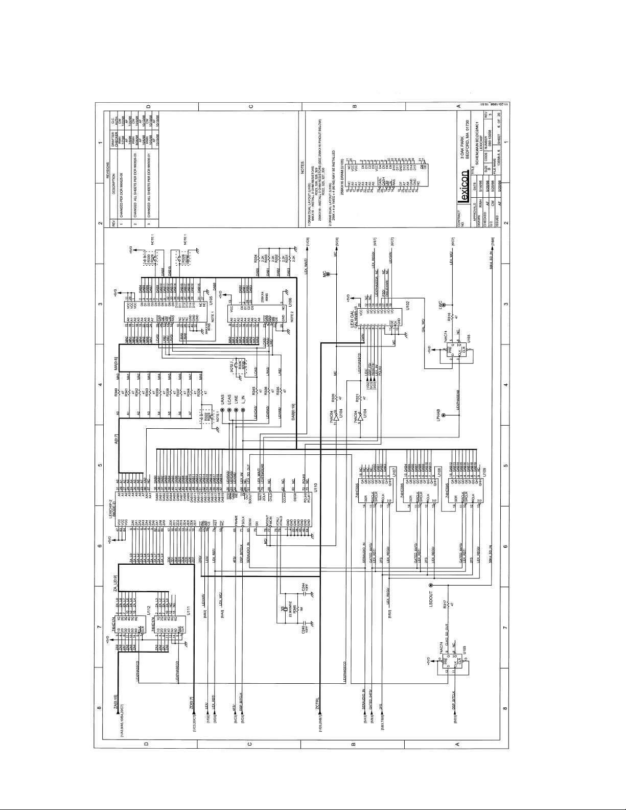
7-13
Page 60

Your Notes:
7-14
Page 61

7-15
Page 62

Your Notes:
7-16
Page 63

7-17
Page 64

Your Notes:
7-18
Page 65

7-19
Page 66

Your Notes:
7-20
Page 67

7-21
Page 68

Your Notes:
7-22
Page 69

7-23
Page 70

Your Notes:
7-24
Page 71

7-25
Page 72

Your Notes:
7-26
Page 73

7-27
Page 74

Your Notes:
7-28
Page 75

7-29
Page 76

Your Notes:
7-30
Page 77

7-31
Page 78

Your Notes:
7-32
Page 79
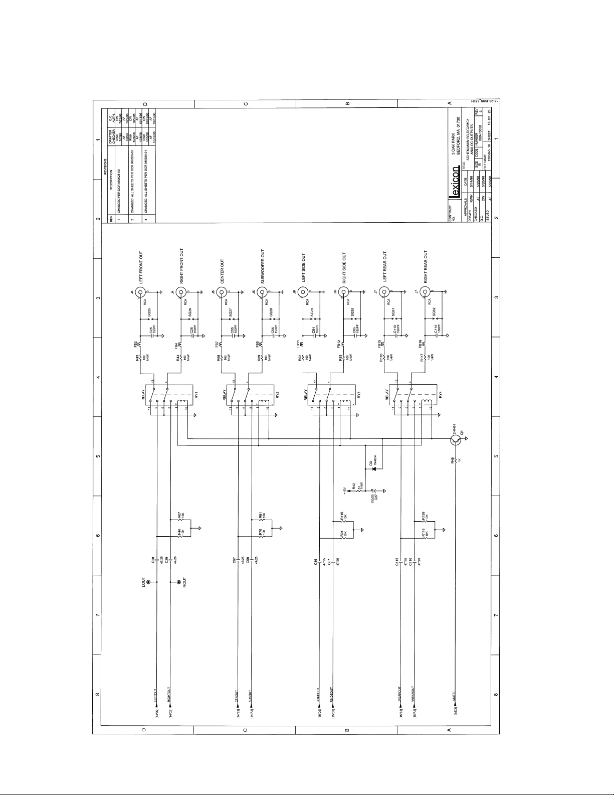
7-33
Page 80

Your Notes:
7-34
Page 81
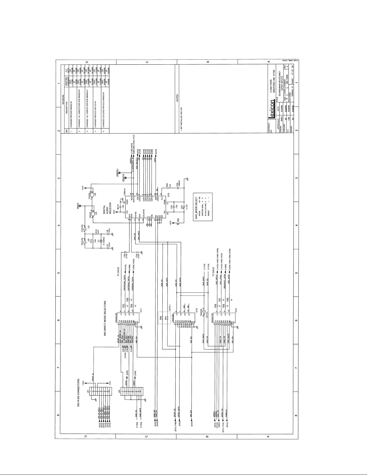
7-35
Page 82

Your Notes:
7-36
Page 83

7-37
Page 84

Your Notes:
7-38
Page 85

7-39
Page 86

Your Notes:
7-40
Page 87

7-41
Page 88

Your Notes:
7-42
Page 89

7-43
Page 90

Your Notes:
7-44
Page 91

7-45
Page 92

Your Notes:
7-46
Page 93

7-47
Page 94

Your Notes:
7-48
Page 95

7-49
Page 96

Your Notes:
7-50
Page 97

7-51
Page 98

Your Notes:
7-52
Page 99

7-53
Page 100

Your Notes:
7-54
 Loading...