

Page 1
CP-1
Digital Audio
Environment
Processor
Panorama Ambience
Reverb Surround
Owner's
Manual
Page 2

Unpacking and Inspection
After unpacking the CP-1, save all packing materials in case you ever need to ship the unit. Thoroughly inspect the
CP-1 and packing materials for signs of damage. Report any shipment damage to the carrier at once; report equipment
malfunction to your dealer.
Precautions
This equipment generates and uses radio frequency energy and if not installed and used properly, that is, in strict accordance
with the manufacturer’s instructions, may cause interference to radio and television reception. It has been type tested and
found to comply with the limits for a Class B computing device, in accordance with the specifications in Subpart J or Part
15 of FCC Rules, which are designated to provide reasonable protection against such interference in a residential installation. However, there is no guarantee that interference will not occur in a particular installation. If this equipment does cause
interference to radio or television reception, which can be determined by turning the equipment OFF and ON, the user is
encouraged to try to correct the interference by one or more of the following measures:
Reorient the receiving antenna
Relocate the computer with respect to the receiver
Move the computer away from the receiver
Plug the computer into a different outlet so that the computer and receiver are on different branch circuits
If necessary, the user should consult the dealer or an experienced radio/television technician for additional suggestions. The
user may find the following booklet prepared by the Federal Communications Commission helpful:
“How to Identify and Resolve Radio/TV Interference Problems”
The booklet is available from the U.S. Government Printing Office, Washington DC 20402, Stock No. 004-000-00345-4.
Acknowledgements
The CP-1 is manufactured under license from Dolby Laboratories Licensing Corporation. Additionally licensed under one
or more of the following patents: U.S. numbers 3,632,886, 3,746,792 and 3,959,590; Canadian numbers 1,004,603 and
1,037,877. “Dolby” and the double-D symbol are trademarks of Dolby Laboratories Licensing Corporation.
3 Oak Park
© 1991, 2000
All Rights Reserved
Patents are pending on the CP-1
Bedford, MA 01730 USA
Tel: 781-280-0300
Fax: 781-280-0490
email info@lexicon.com
06/00 | Lexicon Part No. 070-06619 | Rev 3.0
www.lexicon.com
Page 3

Safety Suggestions
Read Instructions Read all safety and operating instruc-
tions before operating the unit.
Retain Instructions Keep the safety and operating instruc-
tions for future reference.
Heed Warnings Adhere to all warnings on the unit and in the
operating instructions.
Follow Instructions Follow operating and use instructions.
Heat Keep the unit away from heat sources such as radia-
tors, heat registers, stoves, etc., including amplifiers which
produce heat.
Ventilation Make sure that the location or position of the unit
does not interfere with its proper ventilation. For example, the
unit should not be situated on a bed, sofa, rug, or similar
surface that may block the ventilation openings; or, placed in
a cabinet which impedes the flow of air through the ventilation
openings.
Wall or Ceiling Mounting Do not mount the unit to a wall or
ceiling except as recommended by the manufacturer.
Power Sources Connect the unit only to a power supply of
the type described in the operating instructions, or as marked
on the unit.
Servicing Do not attempt any service beyond that described
in the operating instructions. Refer all other service needs to
qualified service personnel.
Damage requiring service The unit should be serviced by
qualified service personnel when:
the power supply cord or the plug has been damaged,
objects have fallen, or liquid has been spilled into the
unit,
the unit has been exposed to rain,
the unit does not appear to operate normally or exhibits
a marked change in performance,
the unit has been dropped, or the enclosure damaged.
Outdoor Antenna Grounding If an outside antenna is
connected to the receiver, be sure the antenna system is
grounded so as to provide some protection against voltage
surges and built-up static charges. Section 810 of the National Electrical Code, ANSI/NFPA No. 70-1984, provides
information with respect to proper grounding of the mast and
supporting structure, grounding of the lead-in wire to an
antenna-discharge unit, size of grounding conductors, location of antenna-discharge unit, connection to grounding
electrodes, and requirements for the grounding electrode.
See figure below.
Grounding or Polarization* Take precautions not to defeat
the grounding or polarization of the unit’s power cord.
*Not applicable in Canada.
Power Cord Protection Route power supply cords so that
they are not likely to be walked on or pinched by items placed
on or against them, paying particular attention to cords at
plugs, convenience receptacles, and the point at which they
exit from the unit.
Nonuse Periods Unplug the power cord of the unit from the
outlet when the unit is to be left unused for a long period of
time.
Water and Moisture Do not use the unit near water — for
example, near a sink, in a wet basement, near a swimming
pool, near an open window, etc.
Object and liquid entry Do not allow objects to fall or liquids
to be spilled into the enclosure through openings.
Cleaning The unit should be cleaned only as recommended
by the manufacturer.
Power Lines An outside antenna should be located away
from power lines.
Page 4

CP-1 Digital Audio Environment Processor
1 Controls and Indicators
Introduction 1
The Front Panel 2
The Rear Panel 3
The Remote Control 4
2 Connection and Calibration
Installation 7
Connections to Other Equipment 7
Setting the Main Input
and Output Levels 9
Calibration of the
Panorama Program 11
3 Speaker Set-Up and Configuration 13
4 Using The Programs
To Load, Modify
and Store Programs 19
The Programs:
Panorama 21
Ambience 22
Reverb 24
Surround 26
To Rename and Store
a Register 29
5 Troubleshooting 31
6 Theory and Design 35
7 Specifications 53
Table of Contents
Page 5

Controls
1
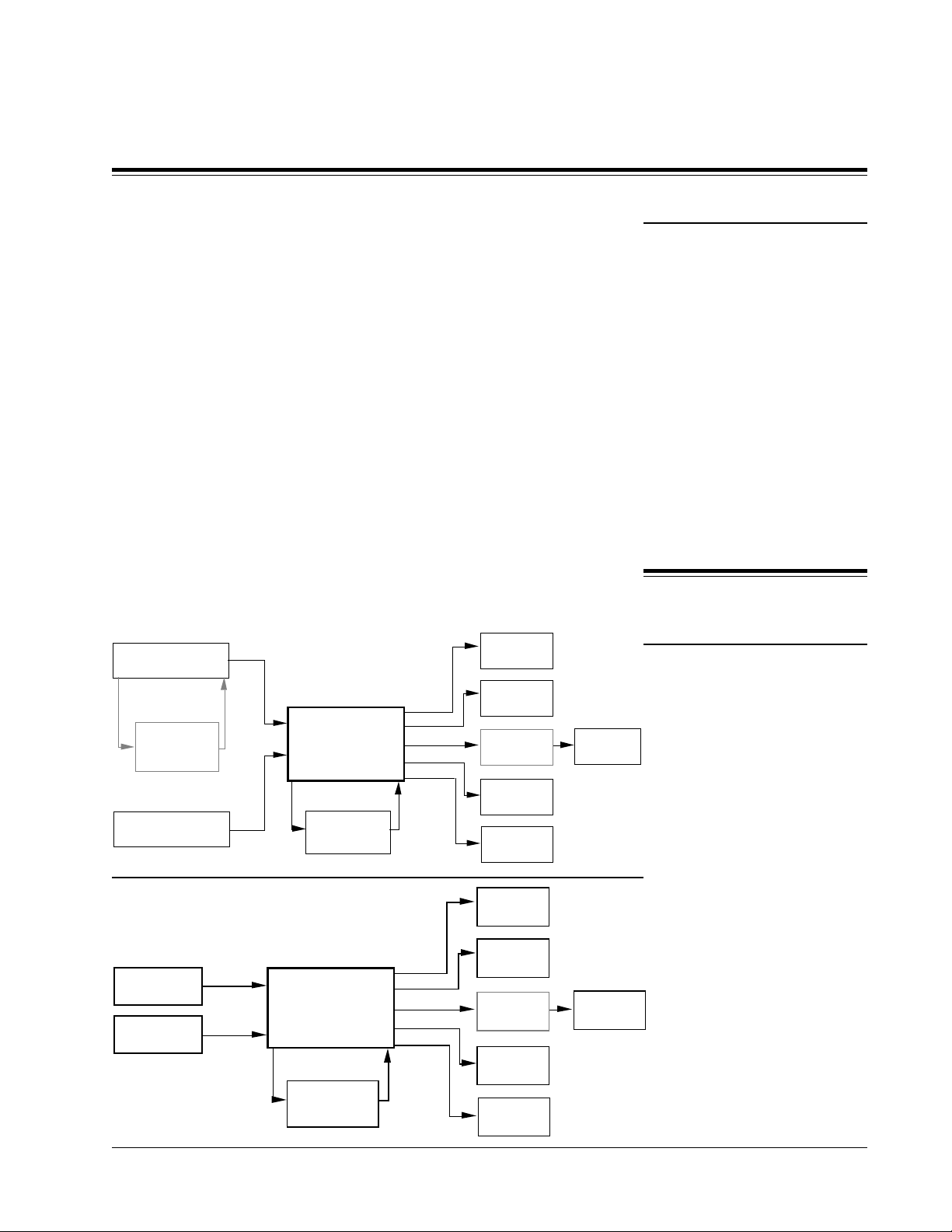
All of the programs in the Lexicon CP-1 Digital Audio Environment
Processor have a common goal: to draw you, the listener, more deeply into
a musical performance or a film. For music the CP-1 uses unique digital
processing to re-create either the original recording space or a new one of
your choosing. For films it offers an extremely accurate version of Dolby Pro
Logic Surround decoding and our own decoding for monaural film soundtracks. The increase in impact of a musical performance or film when heard
with the CP-1 is enormous, especially when widely spaced multiple loudspeakers are provided, but even without additional loudspeakers significant gains are made.
To re-create the experience of being at a performance the CP-1 draws on
recent studies of concert-hall acoustics, and applies this research to home
listening rooms. The object is to increase the sideways-moving sound in a
room, thus increasing Spatial Impression, or SI.
The CP-1 increases SI by either extracting it from the original recording,
using the Panorama or Surround programs, or by generating a new acoustic
environment with Ambience or Reverb.
When a listener is in the correct spot the Panorama program provides an
almost ideal re-creation of the original recording space. It works by using
digital processing to cancel the crosstalk between the listener's ears, effectively spreading the sound from the two front loudspeakers in a wide arc in
front of the listener. With the optional addition of rear speakers, Panorama
can be almost spooky in its realism.
The CP-1 Reverb and Ambience programs provide signals for driving
widely spaced side and rear loudspeakers, directly exciting sideways
sound and heightening the listener impact over a large listening area.
(When there are no side speakers, Panorama is used to increase the sideways sound from the main speakers.)
The Ambience and Reverberation programs transform the listening room
into a new acoustic space, letting you choose an environment which
matches your music or your mood. Unlike some previous hall simulators,
the CP-1 provides full stereo processing. The Ambience program generates
the side and rear reflection patterns of idealized rooms and concert halls.
The larger spaces add the true depth and realism of a concert hall to classical
and popular music, while the smaller spaces are ideal for jazz and rock. The
Reverberation program is similar, but places more emphasis on rich, dense
reverberant decay than on early reflections. It is especially good for
simulating large, highly reverberant spaces.
For films encoded with Dolby Stereo, Lexicon has incorporated into the
CP-1 the first completely digital Dolby Pro Logic Surround decoder, and the
only one with automatic correction of azimuth and channel-balance errors
(the most common problems in currently available films). The CP-1 also
provides a program for playing music through a Surround speaker set-up
(Stereo Logic), and a program for expanding monaural film sound tracks
(Mono Logic).
and
CP-1 Digital Audio Environment Processor
Indicators
Introduction
Page 1
Page 6

Controls and
Indicators
The Front Panel
Lexicon
exicon
I II
SOURCE
DIGITAL AUDIO ENVIRONMENT PROCESSOR CP-1
SOURCE
PRE POSTTAPE SYSTEM
INPUT LEVEL
TAPEMONITOR
Source
The SOURCE buttons select one of two identical stereo pairs of audio
MUTE
TITLE: dlby lgo 2
CREATOR: Adobe Illustrator(TM) 1.1
CR DATE: 6/20/88 3:52 PM
EFFECT
MUTE
POWER
inputs. Ordinarily Input I will be connected to the main outputs of your
stereo preamp and the second input will be a spare. In video installations,
Input I will be connected to the main audio outputs of your TV receiver,
VCR or audio/video control center. Input II can then accept the outputs of
a separate system or the audio outputs of a video disc or CD player.
Monitor
The MONITOR button selects SOURCE I/II or TAPE IN. The Tape inputs
are provided to accommodate a recorder if the CP-1 occupies a previously
used tape monitor loop.
Tape
The PRE and POST Tape switch determines whether CP-1 processing if
applied before or after tape output. PRE means that the tape deck gets the
signal unaltered (PRE-processing); POST applies CP-1 processing to the
tape output (POST-processing).To record CP-1 processing onto tape the
CP-1 must be in the two-speaker mode (Configuration 1) with the POST
button engaged.
Page 2
Input Level
Alphanumeric
Display
Indicator
Lights
Power
The INPUT LEVEL control and its display allow you to match the level of
the incoming signal to the CP-1’s digital encoding circuits. When correctly
set, loud passages will light the entire row of green LEDs without flashing
the red ones.
The alphanumeric display shows both the program that is running and its
modifiable parameters. The CP-1 has 24 registers: PRESETs 1-12 are
configured at the factory; those labeled USER 1-12 are available for storage
of programs customized by the user.
The unlabeled LED to the left of the System Mute Indicator lights when the
CP-1 detects a signal from the remote control. The SYSTEM MUTE LED
indicates that unprocessed audio is no longer passing through to the CP-1's
main outputs. The EFFECT MUTE LED indicates that the CP-1’s processed
audio is no longer passing through to its outputs.
System On/Off.
Page 7
CP-1 Digital Audio Environment Processor
I
II
Controls and
Indicators
The Rear Panel
REAR SIDE
L
R
LEVEL
OUTPUTS
Stereo outputs for rear and side power amplifiers, with level adjusting
knobs. The procedure for balancing these outputs (as well as the center
channel and subwoofer) with the main pair begins on page 9.
Main outputs, with level adjustment. Level-setting of these outputs must
precede adjustment of the auxiliary channels.
The adjustment of the subwoofer output should be done only after all other
channels are calibrated. (See page 11.)
Center channel output with level control and button. Push the button in if
you have no center channel; leave it out if a center speaker is connected.
NOTE: Leaving this button out with no center channel will cause the
Surround programs to malfunction.
MAIN CENTER SUB
L
R
SUB WOOFER
CENTER/OUT
PHANTOM/IN
Rear and Side
Outputs
Main, Center
and Subwoofer
Outputs
Center/Out
Phantom/In
TAPE
TAPE
OUT
L
R
INPUTS
IN
L
R
Inputs and outputs for an additional audio or video tape deck (audio
Tape Out/In
portion only) or to replace the monitor loop occupied by the CP-1.
Two sets of main inputs, selected by the SOURCE I/II buttons.
Inputs
Page 3
Page 8
Controls and
Indicators
The Remote Control
Lexicon
PANORAMA
1 2 3
NORMAL WIDE BINAURAL
TITLE: dlby lgo 2
CREATOR: Adobe Illustrator(TM) 1.1
CR DATE: 6/20/88 3:52 PM
AMBIENCE
4
SMALL
7
SMALL MEDIUM LARGE
SURROUND
MONO STEREO
EFFECT BALANCE VOLUME
DOLBY SURROUND
PRO - LOGIC
5
MEDIUM LARGE
REVERB
8
11 1210
F
B
6
9
R
L
MUTE
BANK
PARAM
EFFECTSYSTEM
Page 4
The Programs
Panorama
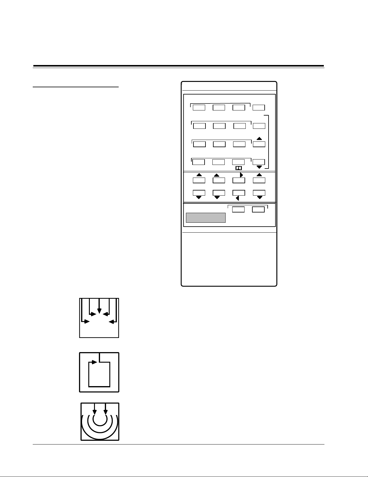
The PANORAMA programs provide enhanced lateral sound (and hence
greater spaciousness and envelopment) for either music or films. This
program can utilize left and right rear channels but is also effective using
only the two front loudspeakers. NORMAL(1) and WIDE(2) differ primarily in their initial Effect Levels. BINAURAL(3) is for playback on loudspeakers of recordings made with a dummy head.
Ambience
The AMBIENCE programs simulate concert halls of three different sizes,
generating reflections of appropriate directionality, delay and spectral
shape and sending them to the side and rear speakers. The Ambience
programs provide adjustable recirculation through the Liveness parameter
but for long reverberation times, use REVERB. Both AMBIENCE and
REVERB are true stereo simulators.
Reverb
The REVERB programs, like AMBIENCE, simulate rooms of three sizes
with the aid of side and rear channels. These programs have fewer specific
initial reflections than AMBIENCE but richer and smoother reverberant
decay. REVERB is especially good for simulating large, highly reverberant
spaces.
Page 9
CP-1 Digital Audio Environment Processor
Controls and
Indicators
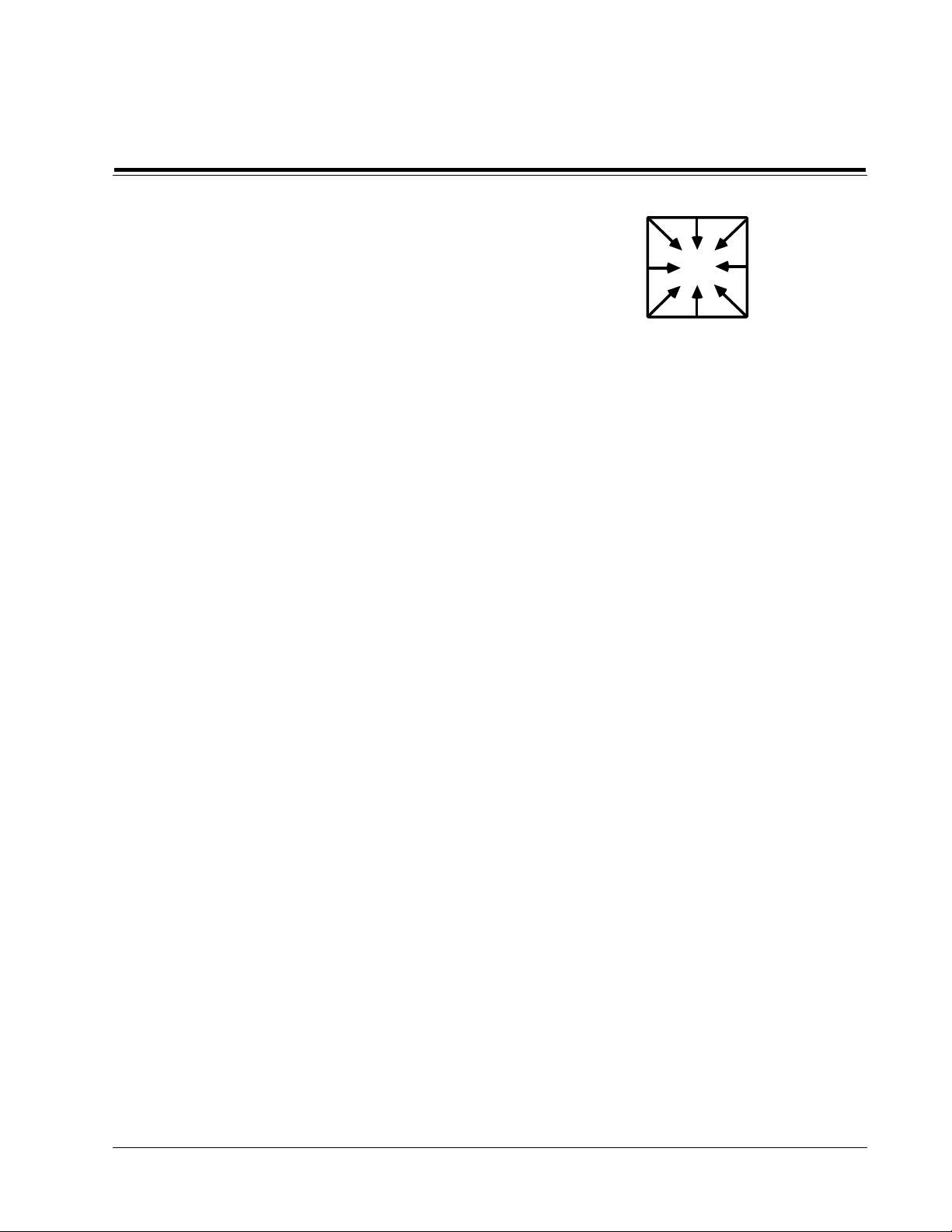
The SURROUND programs work with film sound tracks to recreate the
theater experience. MONOLOGIC (10) expands the music and effects on
monaural films into the additional channels while leaving the dialog in the
front center. STEREO LOGIC (11) enhances music with surround speakers
and also allows the listener to adjust certain parameters for film sound that
are fixed in Program 12. PRO LOGIC (12) provides the same decoding used
in Dolby Stereo theater systems, using up to eight speakers for front, center,
side, rear and subwoofer channels.
The BANK button switches between the 12 factory-preset programs and 12
user registers where customized programs may be stored. The program
number doesn't change: if you are using Preset program 9, BANK switches
to User program 9 and vice-versa. Holding BANK for a few seconds puts
the CP-1 into Configuration mode, in which the three Parameter buttons
adjust the LCD contrast and select one of the 12 speaker setups illustrated
on page 13.
The three PARAMETER buttons allow selection and adjustment of variable
parameters within each program. Pushing PARAM displays the current
parameter for five seconds; pushing it again before the display changes
selects the next parameter. Pressing PARAM UP or DOWN will display and
adjust the current parameter, whether or not PARAM has been pushed. A
single push changes the parameter by one unit; holding the button for more
than one second causes the values to change rapidly in an auto-repeat mode.
PARAM can also put the CP-1 into TEST mode. (See page 19.)
Surround
Bank
Parameter
EFFECT: UP and DOWN adjust the level of all signals added by the CP-1.
BALANCE: F and B adjust the levels of the rear speakers relative to the
sides and fronts.
BALANCE: L and R adjust the left/right balance of all speakers: front, sides
and rear. It assumes the function of the balance control on your preamp or
receiver.
VOLUME: UP and DOWN adjust the level of all channels simultaneously.
It assumes the function of the volume control on your preamp or receiver.
SYSTEM MUTE turns off all outputs and lights both SYSTEM and EFFECT
MUTE LEDs. Pushing EFFECT MUTE while in system- mute mode turns
the effects alone back on.
EFFECT MUTE alternately turns off and on all signals added by the CP-1.
Use it to compare the sound with and without CP-1 processing. In TEST
mode EFFECT MUTE clears all user memories. (See page 19.)
*The first push of either of this pair of buttons displays the current value for five seconds; another push during that time increases or decreases
the displayed value. Holding the button down for 1 second engages auto-repeat.
Effect*
Balance*
Volume*
Mute
Page 5
Page 10

Controls and
Indicators
Lexicon
Page 6
Page 11
2
Connection
and
Calibration
Installation
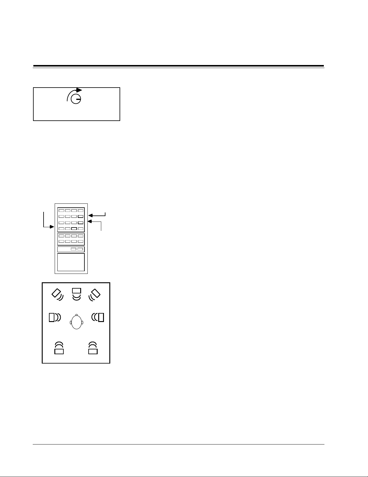
• Make sure the remote control receiver, located on the right side of the
front panel, is unobstructed. The remote control must be in line of sight
to this receiver for proper operation. The CP-1 may be placed in a glassdoored cabinet but smoked glass will make the display hard to read.
• Select a dry, well-ventilated location out of direct sunlight.
• Do not stack the CP-1 directly above heat-producing equipment such as
power amplifiers.
• Avoid placing the CP-1 near unshielded TV or FM antennas. The CP-1
may interfere with some FM tuners if it is placed immediately above or
below them.
• Install two AAA batteries in the CP-1’s remote control.
Precautions
The CP-1 may be installed on a shelf or in a standard 19" equipment rack,
using the optional rack-mounting hardware (Lexicon part #021-06639).
Connect the power cord to a wall outlet or to a switched outlet on the back
of your preamplifier. Observe the following precautions:
Connections to
Other Equipment
I
II
REAR
DYNAMIC RANGE
PROCESSOR
CP-1
INPUTS
CENTER
MAIN OUT
I
II
REAR
MAIN
CP-1
INPUTS
CENTER
CP-1 Digital Audio Environment Processor
AUDIO
PREAMP
TAPE
OUT/IN
PROGRAM EQ
or
VCR, TV, VIDEO
CONTROL CENTER
CD
VIDEO
DISC
MAIN
OUT
AUDIO
OUT
AUDIO OUT
TAPE
OUT/IN
VCR
or
CASSETTE DECK
TAPE
OUT/IN
AUDIO or VIDEO
CASSETTE
RECORDER
MAIN
SIDE
SUB
WOOFER
SIDE
SUB
WOOFER
CENTER
AMP
REAR
AMPS
(SPEAKER
EQ)
SIDE
AMPS
SUBWOOFER
AMP
CENTER
AMP
REAR
AMPS
(SPEAKER
EQ)
SIDE
AMPS
SUBWOOFER
AMP
MAIN
POWER AMPS
Connections with an
Audio Preamp
MAIN
POWER AMPS
Using the CP-1 as an
Audio Preamp
Page 7
Page 12

Connection
I
II
REAR
MAIN
SIDE
CP-1
INPUTS
CENTER
and
Calibration
Lexicon
Connecting the CP-1
in a Tape Monitor Loop
Note
VCR, TV, VIDEO
CONTROL CENTER
AUDIO
OUT
TAPE
OUT
INTEGRATED AMP,
PREAMP or RECEIVER
TAPE
OUT/IN
VCR
or
CASSETTE DECK
TAPE
IN
SUB
WOOFER
CENTER
AMP
REAR
AMPS
SIDE
AMPS
SUBWOOFER
AMP
If you have a receiver with no external access to the preamplifier outputs (or
you wish to use the tape monitor loop on your preamp), you can use a tape
output or external processor loop to the CP-1. However, any change in the
receiver’s volume control after the system is adjusted will upset the balance
between the main and auxiliary speakers. If you are using this configuration, you should now turn the receiver’s volume control all the way down.
If there was a tape deck previously connected to your receiver's monitor
loop, connect it to the CP-1's tape outputs and inputs.
Audio Inputs
Note
Audio Outputs
Turn off ALL audio and video components, including individual power
amplifiers. (Unplug any preamps and power amps that don’t have
switches.) Locate the gain trim potentiometers on the CP-1 rear panel; these
are knobs at the top of the panel, marked REAR, SIDE, MAIN, CENTER and
SUB. Turn each one all the way down (counterclockwise as viewed from
the back).
Connect the main outputs of your audio preamplifier or the preamplifier
output of your receiver to Input I on the CP-1.
Inputs I and II are electrically identical and can be used interchangeably.
The CP-1 will also act as a line-level preamp with three inputs (including the
built-in tape monitor loop) if you wish to connect, for example, the audio
outputs from a TV receiver/monitor, a CD player and a VCR directly to it.
Connect the CP-1’s MAIN outputs to your main stereo channels. Connect
any additional amplifier/speaker combinations to the remaining outputs
on the CP-1: SIDE to the side amplifiers, REAR to the rears, CENTER to the
center- channel amplifier and SUB WOOFER to the subwoofer amp.
Locate the button below the SUB potentiometer marked CENTER/OUT,
PHANTOM/IN. If you have no center front speaker, push it in; if you have
a center channel, make sure this button is in the out position.
Page 8
Page 13

CP-1 Digital Audio Environment Processor
Connection
and
Calibration
Push the INPUT I button on the front panel. Push the MONITOR SOURCE
and TAPE PRE buttons. Turn the INPUT LEVEL knob all the way down
(counterclockwise).
The CP-1 has its own volume and balance controls, which you will be using
in place of the ones on your existing preamp or receiver. Set the gains in your
main stereo channels for optimum dynamic range as follows.
For best performance, the CP-1 should always be driven to its full Input
Level.
Turn on the CP-1. For the first two seconds the display should read:
LEXICON CP-1, with a software version number and a copyright notice.
For another two seconds there will be a configuration message, then a
program name will appear. When the power-up routine is finished, aim the
remote control at the unit and push the EFFECT MUTE button (bottom row,
right). The message: EFFECTS OUTPUTS OFF will appear in the display for
about 4 seconds and the EFFECT MUTE LED on the front panel will light.
Turn on your preamp, choose a signal source and play some loud music (a
heavily compressed FM rock station or heavy-metal CD is ideal). Turn the
preamp’s volume control up about three quarters of the way. Adjust the CP1’s INPUT LEVEL control until the red level-indicator LEDs at the right of
the display blink occasionally, then reduce the INPUT LEVEL until only the
green LEDs are lit.
Front Panel
Adjustments
Setting the
Main Input and
Output Levels
Input Levels
If there are audible differences between the levels of the source you used for
this calibration procedure and other sources, you may have to readjust the
INPUT LEVEL to accommodate them. Where possible, try to use the output
level controls on the various sources to equalize levels.
Push and hold the VOLUME DOWN button on the remote control until the
bar graph on the display completely disappears and the display reads
SYSTEM VOLUME -64 dB. Turn on the main stereo power amplifier, then
hold the VOLUME UP button until the CP-1’s volume is at -05 dB. If the
back-panel potentiometers are turned all the way down, as they should be,
you will not hear any sound yet. If you hear loud sound as the CP-1’s
volume advances, stop and reset all rear-panel gain potentiometers fully
counterclockwise until they are completely off before proceeding.
With the CP-1’s remote volume at -05 dB, slowly advance the rear- panel
potentiometer for the MAIN OUTPUTS until the sound is as loud as you
will normally play the system. Do not touch the gain on your preamp or
receiver after this adjustment. Use only the CP-1 volume control. (Make
sure that this level is not high enough to cause speaker distortion or
amplifier clipping.)
Be sure the Input Level is as high as
possible without flashing red.
Set all output levels to zero; set Volume UP almost all the way.
Page 9
Page 14
Connection
Main Output
and
Calibration
Output Levels
Set Main Output so system is as
loud as you are ever going to need it.
(Be careful that this level does not
cause speaker distortion or amplifier
clipping.)
Balancing
Additional Channels
1. Select
Pro Logic
2.Push Param to
CALIBRATE
3.Push UP
for ON
Lexicon
The output level potentiomenters (the small knobs above the output connectors on the CP-1 rear panel) allow you to balance the sound levels of all
the channels in your system relative to each other. The most important thing
to keep in mind when calibrating the system is to keep these potentiometers
set as low as possible. Your normal listening level (not background muzak
level) shouldbe with the system volume (as indicated by the front panel
LCD) set to around -06dB. This keeps the processor at its optimum signal
levels while allowing headroom if you really want to crank it up.
If you are using only two audio channels, level adjustment is now complete.
If you have additional channels, use the following procedure to set their
levels to match the main stereo pair.
Use the VOLUME DOWN button to reduce the CP-1’s level to about -20 dB.
If the EFFECT MUTE LED is on, push EFFECT MUTE to cancel it. Push
program button 12; the display will read: PRESET 12 on the left and
SURROUND PRO LOGIC on the right. Push PARAM four times or until
the display reads: CALIBRATE. Push PARAM UP to turn on the calibration
signal.
Adjust other output levels until all
directions are equally loud.
The sound you hear is a band of noise centered around 1 kHz, being sent in
sequence to: all channels, left side plus left front, center, right side plus right
front and rear channel(s). If you have a center speaker, the rear-panel
CENTER/PHANTOM button should be out. Since all levels are down
except for MAIN, you will hear only: both fronts, left only, silence, right
only, silence. If you have no center speaker, the rear-panel button should
be in and you will hear: both fronts, left-only, both fronts,right only, silence.
Now turn on the remaining power amplifiers and turn up SIDE, REAR and
CENTER gain until the individual loudness of the sounds reaching your
listening position is the same and the all-channel signal is evenly distributed
from all speakers. The CALIBRATE ON display will remain for as long as
you use this mode. When the front, center, side and rear channels are
balanced, press PARAM DOWN to turn off the calibration signal.
Finally, if you are using a separate low-frequency channel, use music or the
test signal of your choice to adjust the SUB WOOFER gain until the low bass
balances the rest of the spectrum. This completes the initial connections and
level adjustments of the CP-1.
Page 10
Page 15

CP-1 Digital Audio Environment Processor
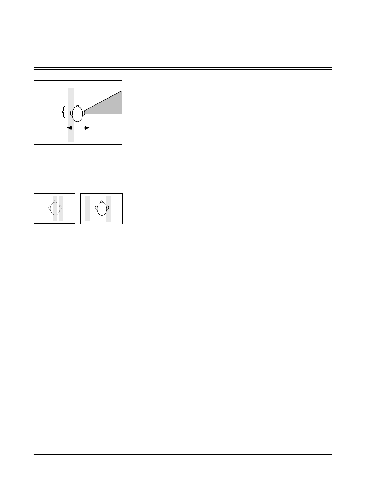
PANORAMA works by canceling the sound going from each speaker to the
opposite ear. The effectiveness of the program is highly dependent on the
geometry of your front loudspeakers, the room and your listening position.
The correct timing of the canceling signal varies with the angle between
your main speakers. The SPEAKER ANGLE parameter, displayed in degrees, adjusts for wide or narrow speaker spacing. For the two canceling
signals to arrive at both ears at the same time you must be centered precisely
between the speakers. The Listener Position parameter (LISTENER POS)
delays the corrections from either channel and allows adjustment for an offcenter listening chair or for asymmetrical speaker placement.
Connection
and
Calibration
Calibration of the
Panorama Program
60°
60°
The ideal setup for Panorama is an acoustically dead room, with speakers
well away from the walls, and the listener on the center line between the
speakers. The effect is diminished by reflections from nearby surfaces.
Furthermore, if the listener sees the two speakers from different angles their
responses will differ. The addition of acoustic absorption (soft furniture,
carpets and drapes) or diffusion (furniture or books that form irregular
surfaces and break up reflections) and time spent shifting speakers and
chair into more precise alignment (use a tape measure rather than relying
on your eyes) will all be rewarded.
Find a mono source, such as an announcer on FM radio or a mono film, and
listen for a tightly focused center image of speech or singing. If the image
is off-center, adjust the CP-1's BALANCE control. (The narrower the
monaural image, the better Panorama will work.) Perform the following
setup from a relaxed, comfortable position in your listening chair with your
head facing the center point between the speakers.
1. Reduce the volume to about -20 dB. If the display reads: PRESET at the
top left, push Program button 2; if not, push BANK, then button 2 to load
PRESET PANORAMA WIDE. Push PARAM eight times (until the
display reads: CALIBRATE OFF). Push PARAM UP to turn on the leftchannel calibration signal.
2. The test signal should appear to come from off to your left side, well
beyond the left speaker, with near-total silence in the right ear. Still
facing forward, move your head from side to side until the effect is
strongest. If you can find the sweet spot from the confines of your chair,
go directly to step 4; otherwise perform step 3.
3. Push PARAM once so the display reads: LISTENER POS. Push PARAM
UP and DOWN until you hear the strongest effect. Then push PARAM
four times, or until the display reads: CALIBRATE LEFT ONLY.
SPEAKER ANGLE is the angle between the main speakers as seen from
the listening position -here it is about
60°.
Select Panorama; Push PARAM to
display: CALIBRATE; then push
Param UP to: ON LEFT ONLY.
SILENCE
NOISE
Move your head from side to side to
find the position where the noise is
full left, and the right ear hears nothing.
}
4. Push PARAM UP until the display reads: CALIBRATE RIGHT ONLY.
Again, shift your head from side to side to find the sweet spot, this time
looking for the point where the silence in the left ear is deepest. Compare
the locations of the two sweet spots from steps 2 and 4. If they coincide,
Page 11
Page 16
Connection
and
Calibration
SILENCE
NOISE
Push PARAM UP again for RIGHT
ONLY. If your left ear is in the silent
band, the speaker angle is correct.
Repeat for the right side.
Lexicon
go on to step 6; otherwise, perform step 5.
5. Push PARAM twice so the display reads: SPEAKER ANGLE. If the sweet
spot from step 2 (LEFT ONLY) is to the left of the sweet spot from step
4 (Right ONLY), push PARAM UP once. If the the step 2 sweet spot is to
the right of the step 4 sweet spot, push PARAM DOWN. Push PARAM
to return to CALIBRATE RIGHT ONLY and go back to step 2.
6. Adjust your chair so the single sweet spot is in the center, or use PARAM
to get to LISTENER POS and adjust this parameter to move the sweet
spot to where you want it. Use PARAM to step to CALIBRATE and push
PARAM DOWN until the calibration signal goes off.
The Panorama Program is now calibrated. To store it, see page 27. Use
PARAM to display the final values of LISTENER POS and SPEAKER
ANGLE. Note these values and use them for all forms of Panorama,
including the Panorama subsections of AMBIENCE and REVERB.
If the two silent bands are too close,
raise SPEAKER ANGLE; if too far
apart, lower SPEAKER ANGLE.
To store, see page 29.
Page 12
Page 17
Speaker
Set-Up and
CP-1 Digital Audio Environment Processor
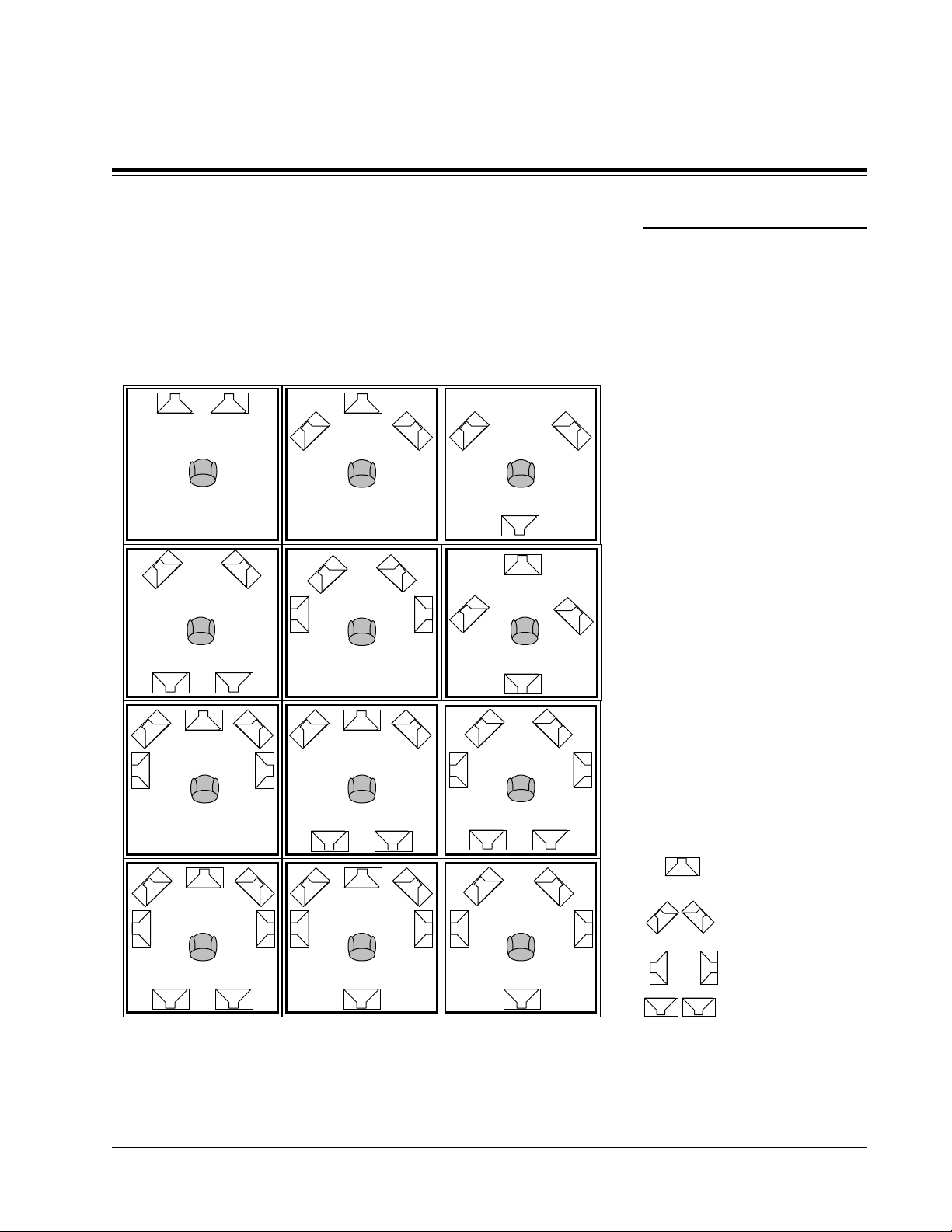
Choose the diagram from the Speaker Configuration Chart that corresponds to your room and note its number. Press the BANK button and hold
it for a few seconds. The display will read: LCD CONTRAST ADJ with a
bright bar. The CP-1 is now in Configuration mode. Within this mode,
operations are carried out using only the three PARAM buttons. Configuration mode will be canceled if any other button is pressed or if 10 seconds
pass without a button push.
Center Phantom
Button IN
1
2
Center Phantom
Button IN
3
Configuration
3
Configuration
Speaker Configurations
Subwoofers are not shown in any of these
configurations. Consult the subwoofer
owner's manual or your dealer for proper
placement of subwoofers, remembering
that corners are almost always best.
Side and rear speakers may sound better if
mounted above the listener, (See Page 15.)
Center Phantom
Button IN
4
7
Center Phantom
Button IN
5
8
10 11 12
6
Center Phantom
Button IN
9
Center Phantom
Button IN
speaker connected to
center output
speakers connected to
Main outputs
speakers connected to
Side outputs
speakers connected to
Rear outputs
Press the PARAM UP or DOWN buttons until the contrast of the display is
at a maximum as seen from your listening chair. Then push PARAM to
enter the Configuration menu. Consulting the Speaker Configuration
Chart, push PARAM UP or DOWN until the figure and the description in
the display match your room.
Note: If you are using only one rear
speaker it may be hooked up to either
the left or right rear output, as long
as you use the correct Configuration
number.
Page 13
Page 18

Speaker
Set-Up and
Configuration
Lexicon
Notes on
Amplifiers
Notes on Speaker
Placement
For Film
How much power do you need? That depends on a number of variables —
How efficient are your speakers? How big is the room? How loud do you
play the system? Generally, the demands on the side and rear channels are
higher for film sound than for music. The center channel is actually the most
important channel on most film soundtracks. Your center amp/speaker
combination should be able to achieve the same sound pressure levels as the
main left and right speakers. Increasing the Bass Blend parameter in the Pro
Logic and Stereo Logic modes will help relieve the center channel of the
heavy low frequency demands, but is not a suitable substitute for a decent
amp/speaker combination. The surrounds will not generally require quite
as much power, but there can be substantial energy requirements during
crescendos. Consider at least 45-60 watts minimum for your rear channel
amplifier.
The CP-1’s Configuration routine allows a wide range of choices in speaker
and room set-ups to maintain optimal performance as your system expands. If you are starting with a conventional two-channel system, in what
order should you add additional channels? The answer depends on
whether you are primarily interested in audio or video.
Page 14
2
Good
6
Better
The film enthusiast with only two stereo speakers should place them
relatively close on either side of the screen and use Panorama for both music
and films. Beyond this, the very first priority should be a center channel
above or below the screen for dialog (Configuration 2). An alternative is
Configuration 3, in which two front speakers and one rear are used with
either the Panorama or Pro Logic programs.
A dramatic improvement will be noticed when increasing from two or three
speakers to four. These should be arranged as in Configuration 6, but with
the front left and right speakers spread quite wide, perhaps all the way
around to the sides — making a diamond pattern with the listener in the
center. How widely you space the front channels will depend on how
deeply immersed in the sound track you want to be; the full diamond
configuration can considerably heighten the sense of emotional involvement in many movies. This arrangement has the advantage of using
amplifiers and speakers in pairs.
10
Best
Page 19

CP-1 Digital Audio Environment Processor
If your center channel speaker is smaller than the left and right fronts,
increasing BASS BLEND will remove low bass from the center and increase
it in the left and right speakers. The center channel is so important that if it
is not possible to have an extra center speaker it is frequently better to plug
the center output of the CP-1 into the audio input of your video monitor and
use its built-in speaker (if it has one) than it is to run the dialog through the
main loudspeakers.
If the system will have a direct view (as opposed to projection) television,
a shielded speaker must be used to prevent interference with the picture.
Only one speaker should be used, as using two speakers to reproduce a
mono signal may cause loss of intelligiblity through inter-speaker interference (comb filtering).
The center speaker should be placed as close to the TV as possible, and as
close to the horizontal axis of the main speaker's tweeters as possible. Side
speakers should be at the sides, or a little forward, of the listening position.
If the system is for music only (no film), the sides can be as far as 20 degrees
behind the listener. For film use, they should be slightly ahead of the
listener. Place the sides at, or slightly above, ear level. Ceiling placement is
not recommended, as this will reduce the stereo separation and will be quite
strange for film, where Pro Logic sends the same information to the sides
and fronts. The rears should be separated as much as possible and kept
away from the listener. Here, ceiling mounts are acceptable, as is mounting
hig (or in) the rear or back side walls.
Speaker
Set-Up and
Configuration
The best set-up for those who like both music and films is Configuration 10.
The addition of side speakers allows all forms of source material to be
palyed without compromise.
The button on the back of the CP-1 labeled CENTER OUT/PHANTOM
IN is very important in the operation of the Surround programs. Make
sure the button is out if you have a center speaker and in if you have none.
With the button in (Phantom Mode) the center channel is mixed in with
the two main outputs; the side outputs carry the Left and Right signals;
the center channel is turned off.
Page 15
Page 20

Speaker
Set-Up and
Configuration
Lexicon
For Music
Center Phantom
Button IN
1
Good
Center Phantom
Button IN
5
Better
Center Phantom
Button IN
9
Best
If your main interest is music, you will most likely begin with two highquality main speakers (Configuration 1). Here the Panorama program
alone will add substantial enhancement in spatial impression, image size,
image depth and freedom from coloration of central sources.
The audiophile’s first addition should be two side channels (Configuration
5) and, after that, two rear channels (Configuration 9). For maximum effect
with the Reverberation programs, two additional speakers can be placed in
the front corners of the room, driven from the rear amplifiers. The side
speakers, however, are the most important.
With Configuration 5, movies can be played with the Pro Logic program;
the rear-channel sound will automatically be routed to the side speakers. If
you have six speakers (Configuration 9) an additional stereo amplifier can
power both a center channel and a subwoofer.
Page 16
The height of the extra speakers will depend on the furnishings in the room.
In real halls much of the reflected energy comes from above, and placing the
side and rear speakers above the listener can be very effective. They also
work well on normal speaker stands. Placing the speakers too high in a
narrow room may reduce the spaciousness, since this makes the sound
come from the ceiling instead of the side walls.
Page 21

CP-1 Digital Audio Environment Processor
Speaker
Set-Up and
Configuration
The Subwoofer Output is a monaural signal created by summing the left,
right and center outputs, then filtering out frequencies above 100 Hz at a
rate of 12 dB per octave.
Connecting a subwoofer to the CP-1 rear-panel Subwoofer Output, adds
bass energy without removing any from your main speakers. Note, however, that many of the subwoofers curently on the market have their own
crossover (complementary low and high pass filters) and amp built in.
Often it is better not to use the CP-1 Subwoofer output (which is already
filtered at 100Hz 12dB/octave). Instead, we recommend using the main
outputs as follows.
Connect the CP-1 main (front) and left and right outputs to the inputs of the
subwoofer crossover. Then connect the subwoofer output (high pass filtered version of the input) to the amplifier driving the main speakers. This
has the advantage of bi-amping the main speakers — all the low bass is
handled by the subwoofer and the main speakers only handle mid-bass on
up. This usually reasults in a better-sounding main speaker.
If you want to run the main speakers full range, the subwoofer can be wired
in parallel to the main amp using a Y-connector. Alternatively, the CP-1
Subwoofer ouput can, of course, be used. If there is not enough gain for the
subwoofer (because it's being filtered by both the CP-1 and its own crossover), use one of the methods described above.
Subwoofer Connections
Since the center channel will still be runing full range, you should use the
Bass Blend parameter in the Pro Logic and Stereo Logic modes. This protects
the center channel speaker by splitting low frequencies off the center
channel and feeding them to the left and right front outputs. Remember to
turn up this parameter in any User Register you program, particularly in
Stereo Logic. A little experimentation goes a long way in determining the
optimum value for Bass Blend. Around 6 is usually best. When this
parameter is set too high, some male vocals will sound chesty; too low and
you lose bass.
Page 17
Page 22

Speaker
Set-Up and
Configuration
Lexicon
Page 18
Page 23

Using the
CP-1 Digital Audio Environment Processor
The CP-1 contains four basic programs: Panorama, Ambience, Reverb and
Surround. Each program has three variations which occupy one row on the
remote control.
Pushing one of the buttons numbered 1 through 12 during normal operation will load that program. Whenever the CP-1 is turned on, it will load the
program that was running when it was turned off.
Each program has a number of parameters that you can vary with the three
PARAMETER keys. The parameters for each program are listed in the
section on individual programs. The PARAM key displays the current
parameter and its value for about five seconds. If PARAM is pushed during
this period it will select the next parameter. Pushing the PARAM UP or
DOWN keys at any time will display and change the parameter’s value in
the direction you have selected.
The CP-1 contains a total of 24 program registers organized into two banks
of 12 each. Each of the 12 program buttons, therefore, will load one of the
factory presets or one of the 12 user registers, depending on which bank is
currently in use. The factory preset programs are denoted by: PRESET in the
upper left of the display, with the program number beneath. The program
title appears in the right half of the display, with the basic program name
above and the variation below. The BANK button switches between
whichever of the 12 PRESET variations is running and the corresponding
USER register or vice-versa. For example, if you are running USER 7,
pressing BANK will switch to PRESET 7.
While running a Preset program you can change any of its parameters to see
how they affect the sound. These changes will be lost when you turn the CP1 off or change programs, unless you explicitly store the changes. (See page
27.)Changes made in the value of parameters within a User program,
however, are stored with that program immediately and automatically.
This includes settings of EFFECT LEVEL and FRONT/REAR BALANCE
but not of the LEFT/RIGHT BALANCE or VOLUME controls. You do not
have to perform any specific storage routine to create a new variation in a
User register; it happens whenever you change a parameter.
Programs
4
To Load, Modify and
Store Programs
To load a program:
1. Push BANK to select
USER or PRESET
BANK
PARAM
2. Push a program # to load.
3. Changes to PARAM, EFFECT
LEVEL and F/B BALANCE store
automatically in USER Bank.
FLR
EFFECT BALANCE VOLUME
B
4. To store changes for a PRESET
Bank program, see page 27.
When the CP-1 leaves the factory each User register contains a duplicate of
the Preset program of the same number. If you maintain this arrangement,
the labels on the remote will continue to describe the contents of both
registers. You can, however, store a version of any program in any of the
User registers.
The CP-1’s User registers can be cleared and reloaded with duplicates of the
factory Preset programs at any time. Press and hold the PARAM key while
you turn the CP-1 on; continue to hold down PARAM for 5 seconds. This
puts the unit into TEST mode. Push EFFECT MUTE to clear and reload the
User registers and to restore all initial settings of Volume, Balance, Contrast,
Configuration, etc. The display will read: RESTORE DEFAULTS. Push
PARAM again to begin normal operation.
Test Mode
MUTE
EFFECTSYSTEM
Page 19
Page 24

The Programs:
Panorama
Lexicon
Panorama
Panorama extracts the natural ambience from recorded music and moves it
outward from the speakers, producing greater width and depth of image
and a feeling of enhanced spaciousness. The program adds no additional
sound but expands the existing stereo image. Panorama also works with
Dolby Stereo movies, bringing the surround track outward into the room.
Panorama works with just two loudspeakers. If side speakers present,
Panorama disables them and substitutes its own simulation. The front
speakers are driven entirely from the CP-1’s digital circuits. Panorama will
also send a stereo difference signal (left channel minus right or vice-versa)
to the rear loudspeakers if you have them. NORMAL (1) will provide
enough expansion for most music, while WIDE (2) has a more pronounced
effect on the image. BINAURAL (3) has special low-frequency compensation and is meant specifically for true binaural recordings made with a
dummy head.
Panorama NORMAL is designed to work with recordings whose bass
energy is evenly distributed across the stereo image. Panorama WIDE is
designed for recordings with centered bass (almost all pop and rock). The
only other difference between these two programs is their initial EFFECT
LEVEL. If you need more bass from Panorama NORMAL, switch to WIDE
and reduce the EFFECT LEVEL. Conversely, if Panorama WIDE is too bassheavy, switch to NORMAL and increase the EFFECT LEVEL.
Note
The location of the front speakers and the listening position are crucial to
Panorama’s effectiveness and for best results your system and the CP-1
together should be set up and calibrated according to the procedure on page
10. The strength of the Panorama effect drops off as you move away from
the prime listening position, especially to the sides. Video systems with the
main loudspeakers spaced closely on either side of a TV screen will produce
a diminished effect over a somewhat wider area than set-ups with a large
included angle between the speakers.
Program
Parameters
Parameter Initial Value Range
INPUT BALANCE
LISTENER POS
SPEAKER ANGLE
LF WIDTH
REAR LEVEL
REAR ROLLOFF
REAR DELAY
CALIBRATE
SET PROGRAM NAME
MEMORIZE PROGRAM
(Centered)
127
49 degrees
0
16*
2.9 kHz
16 ms
OFF
NA
NA
Full Left-Full Right
329 Hz-14.1 kHz
Left, Right, Both
0-254
29-90 degrees
-25 - +25
0-32
0-32 ms
NA
NA
Page 20
* 0 in BINAURAL, or if no rear speakers specified
Page 25

CP-1 Digital Audio Environment Processor
The Programs:
Panorama
EFFECT LEVEL sets the amount of crosstalk cancellation, and thus the
apparent front width. It is the most important user adjustment to Panorama,
and has been given its own button on the remote. When EFFECT LEVEL is
all the way down, Input Balance, LF Width and the rear outputs are still
active.
INPUT BALANCE compensates for the occasional source with audible
channel imbalance. It is especially important when using Panorama for
movies. If the movie sound tracks are unbalanced, the dialog will wander
away from the center; adjusting the Input Balance corrects for this.
LISTENER POS and SPEAKER ANGLE are determined using the calibration procedure on page 10. The resulting value for Listener Position should
then be used for the Panorama sections of Ambience and Reverb.
LF WIDTH controls the amount of low-frequency spatial correction that is
applied to the signal. A positive value of LF WIDTH means the difference
(left minus right channel) signal has additional energy below 500 Hz, while
the sum (left plus right) signal has correspondingly less. (Negative settings
can compensate for recordings with too much of this property.) LF WIDTH
can add needed spaciousness and warmth to classical recordings made with
coincident or near-coincident miking. (See Chapter 5: Theory and Design.)
Effect Level
Input Balance
Listener Position/
Speaker Angle
LF Width
REAR LEVEL adjusts the loudness of the signals sent to the rear channels.
REAR DELAY adjusts the amount of time between the appearance of a
signal in the front channels and its emergence from the rear. Generally, the
correct delay is about 16 milliseconds but the setting depends on speaker
set-up and source material. In general, the delay should not be so great that
the rear sound becomes identifiable as a distinct source.
REAR ROLLOFF sets the frequency above which the rear-channel sound is
attenuated. It should be high enough to give presence and airiness to the
rear sound but not so high as to place distracting instrumental overtones or
other sounds behind you. The appropriate setting will vary with program
material.
The use of the CALIBRATE mode is described in the setup instructions
beginning on page 11.
The procedures for naming a new version of the program (SET PROGRAM
NAME) and storing it in one of the User registers (MEMORIZE PROGRAM)
are described on page 29.
Rear Level
Rear Delay
Rear Rolloff
Calibrate
Set Program Name/
Memorize Program
Page 21
Page 26

The Programs:
Rectangle
4
s/m/l=5.9/3.6/2.9 kHz
28*
128
51 degrees
ON
NA
NA
Rectangle, Fan
0-6
329 Hz-14.1 kHz
0-32
0-254
33-91 degrees
On/Off
NA
NA
Parameter Initial Value Range
Ambience
Ambience
Program
Parameters
ROOM SHAPE
LIVENESS
ROLLOFF
PANORAMA EFF
LISTENER POS
SPEAKER ANGLE
SPEECH DETECTION
SET PROGRAM NAME
MEMORIZE PROGRAM
Lexicon
Ambience generates the appropriate early reflections for stereo simulation
of one of six different halls — one rectangular hall and one fan-shaped hall
in small, medium and large sizes — and sends the reflections to the side and
rear speakers. For systems with only two loudspeakers, Ambience also
incorporates a version of Panorama that will spread the stereo image and
add the reflections it generates to the expanded sound stage.
The initial EFFECT LEVEL is highest for Program 4 and progressively lower
for Programs 5 and 6. It will be easier to hear exactly what the parameters
do if the effect level is temporarily turned all the way up.
Effect Level
Room Shape
Liveness
Page 22
EFFECT LEVEL adjusts the loudness of the side and rear speakers. When
there are no side speakers, it adjusts the amount of ambient signal mixed
into the main loudspeakers. EFFECT LEVEL is the most important user
adjustment in AMBIENCE and REVERB, and has been given its own button
on the remote. It should be adjusted as high as possible without making the
extra speakers individually audible.
ROOM SHAPE selects one of two basic hall shapes. Refer to Chapter 5:
Theory and Design, for a discussion of the properties of the two.
The LIVENESS parameter adjusts the amount of recirculation within the
program. The higher the value, the more reflective the surfaces of the
simulated space and the longer the sound will take to decay. At very high
values the decay is audibly less smooth than in the Reverb programs, which
are more effective at simulating very live spaces.
* 0 if side speakers are specified
Page 27

CP-1 Digital Audio Environment Processor
The Programs:
Ambience
ROLLOFF mimics the absorption of the air in the hall and its initial value is
therefore more pronounced (the rolloff begins at a lower frequency) the
larger the space.
PANORAMA EFFECT adjusts the strength of the signal used to expand the
stereo image outward from the front two speakers. It is only needed when
side speakers are absent.
LISTENER POS compensates for the relative distance of the two main
speakers from the prime listening area. It should be set for the value arrived
at in the Panorama set-up procedure on page 11.
SPEAKER ANGLE compensates for differing distances between your front
speakers. It affects only the Panorama Effect and is only needed when side
speakers are absent. The Speaker Angle can be set to the value reached in
the setup procedure on page 11, but the program may also work well at
lower values.
The image expansion will be strongest at the one location in the room for
which the program has been calibrated (See page 10). It will diminish
somewhat as you move forward or back from that location and more rapidly
as you move from side to side.
Rolloff
Panorama Effect
Listener Position
Speaker Angle
The Speech Detection circuit distinguishes monaural speech from other
inputs. Whenever stereo signals are present, the right and left input channels are used independently as inputs to the ambience synthesis. If there is
a strong monaural speaking voice present at the same time, this component
of the input is reduced while the stereo component is increased. If the input
signal is pure monaural speech the input is almost entirely attenuated.
SPEECH DETECTION is a real benefit to some popular music (where
spoken voice, such as rap, occurs along with music), stereo television, and
early stereo movies. Any stereo material which was not carefully mixed for
Surround is a good candidate for playing through Ambience with SPEECH
DETECTION On.
The procedures for naming a new version of the program (SET PROGRAM
NAME) and storing it in one of the User registers (MEMORIZE PROGRAM)
are described on page 29.
Speech Detection
Set Program Name/
Memorize Program
Page 23
Page 28

The Programs:
NA
NA
Parameter Initial Value Range
0-120 ms
Reverb
Lexicon
Reverb
The Reverberation program differs from Ambience in that it does not
simulate the early reflections of specific halls, but emphasizes rich, smooth
reverberant decay in small, medium or large spaces. It works well for
simulating a space with a long reverberation times relative to its size, such
as a reverberant chamber, church or the like. For systems with only two
loudspeakers, Reverb also incorporates a version of Panorama that will
spread the stereo image and add the reflections it generates to the expanded
sound stage.
The initial EFFECT LEVEL is highest for Program 7 and progressively
lower for Programs 8 and 9. It will be easier to hear exactly what the
parameters do if the EFFECT LEVEL is temporarily turned all the way up.
Program
Parameters
MID RT
BASS RT
TREBLE
PANORAMA EFF
LISTENER POS
SPEAKER ANGLE
PRE-DELAY
SET PROGRAM NAME
MEMORIZE PROGRAM
small-0.46 sec
medium - 0.92 sec
large - 2.16 sec
small-x1 MID RT
medium-1.25xMID RT
large-1.25xMID RT
s/m/l=5.9/4.2/3.6 kHz
0/28*
128
51 degrees
0
NA
NA
0.32 - 2.8 sec
0.64 - 5.6 sec
1.28 - 11.2 sec
0.7 xMID RT
1 xMID RT
1.25xMID RT
329 Hz - 14.1 kHz
1-32
0-254
33-91 degrees
Effect Level
Page 24
EFFECT LEVEL adjusts the loudness of the side and rear speakers. When
there are no side speakers, it adjusts the amount of ambient signal mixed
into the main loudspeakers. EFFECT LEVEL is the most important user
adjustment in AMBIENCE and REVERB, and has been given its own button
on the remote. It should be set as high as possible without making the extra
speakers individually audible.
* 0 if side speakers are specified
Page 29

CP-1 Digital Audio Environment Processor
The Programs:
Reverb
MID RT (Midrange Reverberation Time) is the time required for midrange
sounds to decay 60 dB in level. Your choice of small, medium or large
synthesized space determines both the initial value and the available range
of MID RT.
BASS RT, the low-frequency reverb time, depends on the MID RT and is
expressed as a multiplier. BASS RT is equal to MID RT in Program 7, while
in the medium and large versions of the program it is 25% higher (as is the
case in most actual halls with acceptably warm subjective frequency balance).
TREBLE rolloff, as in the Ambience programs, is preset to mimic air
absorption in actual spaces, being more pronounced in the larger ones.
PANORAMA EFFECT adjusts the strength of the signal used to expand the
stereo image outward from the front two speakers. Its initial value is zero,
unless you have configured the CP-1 for no side loudspeakers.
LISTENER POS compensates for the relative distances of the two speakers
from the prime listening area. It should be set for the value arrived at in the
Panorama set-up procedure on page 11.
Mid RT
Bass RT
Treble
Panorama Effect
Listener Position
SPEAKER ANGLE compensates for varying distance between your front
speakers. The Speaker Angle can be set to the value reached in the setup
procedure on page 11, but the program may also work well at lower values.
The image expansion is strongest at the one location in the room for which
the program has been calibrated. ( See page 11.) It will diminish somewhat
as you move forward or back from that location, and more rapidly as you
move from side to side.
PRE-DELAY increases the delay between the direct sound and the onset of
reverberation. Some pre-delay is inherent in the programs, and the preset
value of 0 is usually a good starting point. Increasing the pre-delay will
make the hall sound larger.
The procedures for naming a new version of the program (SET PROGRAM
NAME) and storing it in one of the User registers (MEMORIZE PROGRAM)
are described on page 29.
Speaker Angle
Pre-Delay
Set Program Name/
Memorize Program
Page 25
Page 30

The Programs:
Surround
Surround
Lexicon
The SURROUND programs are designed for film sound tracks and they
make full use of additional loudspeakers at the center, sides and rear of the
room. MONO LOGIC takes a monaural soundtrack and sends music and
sound effects to the sides and rear through a room simulator program, while
keeping dialog in the center. STEREO LOGIC is meant for playing music
through a system whose speakers are laid out primarily for films. PRO
LOGIC is Lexicon’s all-digital implementation of the Dolby Pro Logic
Surround decoding process.
The term Dolby Stereo refers to both movies and equipment used exclusively for theatrical
presentation. When one of these movies is transferred to commercial video media, the special
audio encoding of the Dolby Motion Picture matrix is retained in the two-channel stereo
soundtrack. The resulting video software and the hardware designed to reproduce it use the
name Dolby Surround to distinguish it from the theatrical optical format.
Dolby Pro Logic Surround decoding is the licensed consumer version of the professional
Dolby Stereo cinema processors, which allows the home viewer to obtain all the spatial
effects of the soundtrack heard in a theatre over a wider range of seating positions than
conventional Dolby Surround playback.
Effect Level
EFFECT LEVEL conrols the level of all channels except the center. The center
will appear stronger if you turn down EFFECT LEVEL a few dB. With
EFFECT LEVEL all the way down, the center only will play.
Program
Parameters
Mono Logic
Parameter Initial Value Range
TREBLE
SET PROGRAM NAME
MEMORIZE PROGRAM
Treble
TREBLE is the only adjustable parameter in MONO LOGIC. It regulates the
treble cut in the side and rear channels. The optimal setting for this
parameter will vary widely with the age, quality and condition of the
source material.
2.3 kHz
NA
NA
329 Hz - 14.1 kHz
NA
NA
Page 26
Page 31

CP-1 Digital Audio Environment Processor
Parameter Initial Value Range
The Programs:
Surround
Stereo Logic
FRONT EFFECT
REAR EFFECT
REAR ROLLOFF
BASS BLEND
AUTO AZIMUTH/BAL
REAR DELAY
REAR NOISE CHIP
CALIBRATE
SET PROGRAM NAME
MEMORIZE PROGRAM
8
8*
14.1 kHz
0
OFF
8 ms
OFF
OFF
NA
NA
* 0 if no rear speakers specified
Pro Logic
Parameter Initial Value Range
REAR DELAY
AUTO AZIMUTH/BAL
BASS BLEND
CALIBRATE
SET PROGRAM NAME
MEMORIZE PROGRAM
20 ms
On
6
Off
NA
NA
0-16
0-16
329 Hz-14.1 kHz
Automatic
0-16
Off, On
0-32 ms
Off, On
Off, On
NA
NA
16-32 ms
Off, On
0-16
Off, On
NA
NA
REAR DELAY in both STEREO LOGIC and PRO LOGIC is adjustable.
Generally, the correct delay is about 20 milliseconds but the setting depends
on speaker set-up and source material. In general, the delay should not be
so great that the rear sound becomes identifiable as a distinct source.
REAR ROLLOFF controls the treble attenuation and should be adjusted on
music for maximum airiness and spatial realism without causing specific
instruments to seem to come from behind you. Stereo Logic’s REAR
ROLLOFF parameter contains an AUTOMATIC mode. In this mode the
rear channels are rolled off above 7 kHz until the logic circuits steer a sound
effect to the rear speakers, whereupon the bandwidth opens up to beyond
15 kHz. This will enhance the realism of some effects that move from front
to rear or vice-versa.
Rear Delay
Rear Rolloff
Page 27
Page 32

The Programs:
Surround
Program Parameters cont'd
Lexicon
Auto Azimuth/
Balance
Bass Blend
Front Effect/
Rear Effect
The AUTO AZIMUTH/BAL parameter should be set to ON for films, OFF
for music. When it is on, special digital circuits continually monitor the
dialog and adjust both the relative level and time offset of the two channels
to keep the dialog properly centered. This automatic feature is why the CP1 does not have or need a front-panel input balance control for Dolby
Surround decoding.
BASS BLEND takes the low bass from the center, where it is in many film
and music mixes, and distributes it instead to the left and right frontchannel speakers. Its initial value is 0 in the Stereo Logic program and 6 in
Pro Logic. This is valuable because in many video installations the center
speaker is smaller than the two main stereo speakers and is, therefore, less
capable of handling the lowest frequencies.
The essence of the Dolby PRO LOGIC circuit is that dialog, music and sound
effects are dynamically directed to the output channels, a process called
steering. The FRONT EFFECT and REAR EFFECT parameters in Stereo
Logic allow you to adjust the amount of this steering. Both are preset for
their maximum values in PRO LOGIC. In STEREO LOGIC, FRONT
EFFECT has a default value of 8, which is equivalent to 6 dB of steering; at
this level, central (monaural) sources are reduced in level by 6 dB in the main
stereo speakers. With FRONT and REAR EFFECT both set to 0, STEREO
LOGIC becomes the equivalent of a simple non-steered Dolby Surround
decoder. If you have no rear speakers, REAR EFFECT should be set to 0. The
CP-1 will set this parameter automatically when you specify a speaker
configuration with no rear channels. (See page 13.)
Page 28
Rear Noise Chip
Calibrate
Set Program Name/
Memorize Program
Dolby Surround decoding specifications call for a special form of Dolby Btype noise reduction. Because STEREO LOGIC is also meant for music, the
rear-channel sound has more flexibility, including REAR NOISE CHIP, a
parameter that allows you to turn this Dolby NR circuit off.
The CALIBRATE mode in Stereo Logic and Pro Logic is for setting up and
checking the levels of the channels in multi-speaker systems. Its use is
covered in the section on Balancing Additional Channels on page 10.
The procedures for naming a new version of the program (SET PROGRAM
NAME) and storing it in one of the User registers (MEMORIZE PROGRAM)
are described on page 29.
Page 33

CP-1 Digital Audio Environment Processor
The previous sections describe the CP-1’s four basic programs and all of
their variable parameters. Any changes in the parameters of a program in
the USER bank will be automatically recorded and stored for future use.
The CP-1 also allows you to store a new version of any PRESET or USER
program in any USER register.
Using the
Programs
To Rename and
Store a Register
USER banks store automatically.
As you cycle through the parameters in any program with the PARAM key
you will come to two labeled: SET PROGRAM NAME and MEMORIZE
PROGRAM. To rename your new program, press the PARAM key until the
display reads: SET PROGRAM NAME. At this point a cursor (the underline
character) appears in the bottom row of the LCD display. Each of the 12
program keys will now move the cursor to one of twelve available spaces in
the display, while the PARAM UP and DOWN keys cycle through the
available list of characters, beginning with the one currently occupying the
space.
With the upper half of the display reading: SET PROGRAM NAME, push
1 on the remote (also marked PANORAMA NORMAL). The cursor will
move to the leftmost column of the program name. Now push PARAM UP
or DOWN until the character you want appears in the space. (Holding
either button for one second activates an auto-repeat mode to speed you
through the list.) All letters are available, in upper or lower case, as are digits
0-9, a blank space and an assortment of other characters. When the first
space in the display is correct, press button 2, set the second character and
repeat until the new name is complete.
As with all the other parameters, a new name composed while a USER
program is running becomes a permanent part of the CP-1’s memory as it
is being written. If you began with a PRESET program, storing a register
takes two more steps: Press PARAM until the display reads MEMORIZE
PROGRAM, then press any of the 12 program keys to store all current
settings in the corresponding USER register. This operation will also switch
the CP-1 to the selected location in the USER bank, causing further pushes
of the program keys to load USER programs instead of PRESETs. (Press
BANK again to return to the factory presets.)
Naming a Register
2. Push program
# to select
a position
1.Push Param to
SET PROGRAM
NAME
3.Push UP/DOWN
to select a
character
Storing a Register
1. Push PARAM to
MEMORIZE PROGRAM
2. Push any program # to STORE
When a PRESET program is running and parameters have been changed,
you can restore the original settings simply by pushing the button for the
displayed program number again. To experiment with a USER program
without changing it requires that you set aside one register for experiments.
If, for example, this “scratch register” is number 12, call up the program you
want to start with, cycle through its parameters until you come to MEMORIZE PROGRAM and press button 12. This will make a duplicate of the
original program in USER register 12, and switch the CP-1 to USER 12. The
parameters of the duplicate can now be modified at will and the new version
stored in any USER register.
Restoring Original
Settings
See also TEST MODE, page 17.
Page 29
Page 34

Using the
Programs
Lexicon
Page 30
Page 35

CP-1 Digital Audio Environment Processor
5
Troubleshooting
Troubleshooting
If you encounter a problem, please review the items in the following
checklist. Also be sure to thoroughly check all other connected components
such as speakers, receiver/amplifier/preamp, VCR, TV, CD player, etc.
Problem Possible Cause and Solution
Input level meters not functioning Make sure INPUT LEVEL on the CP-1 front panel is turned up.
Check the connections on the rear and make sure signal is going
into the CP-1. Check SOURCE and MONITOR switches and try
toggling them in and out.
Make sure that the correct input is selected and that only one input
button is depressed.
Remote control not working Check the batteries and make sure that they are inserted correctly
with proper polarity. Make sure that the infrared receiver on the
CP-1 front panel above the POWER switch is not obstructed. If the
remote control unit is still not functioning, RESTORE DEFAULTS
as described below.
No audio Check input and output connections. They may be reversed
relative to the IN and OUT jacks of your receiver/amplifier/
preamp or other source.
Erratic behavior Power turn-on with large power amps may cause power sags that
will confuse the CP-1. To prevent this, plug the CP-1 into an AC
outlet on a different branch circuit, or turn on one amplifier at a
time.
No output First verify that signal is coming into the CP-1 by observing the
Input Level meters. Increase VOLUME using the Remote Control
and check the Front/Back and Left/Right balances.
Make sure that the rear panel Output Level controls are turned up.
Check the CP-1 mute controls to make sure they are not engaged.
Check all other equipment settings and connections and verify
that the amplifier(s) being fed by the CP-1 are operational.
Display irregularities Adjust the contrast (relative brightness) of the display using the
procedure described on the Quick Reference Guide, and on Page
13 of the Owner's Manual. If the display is showing strange
characters, RESTORE DEFAULTS as describet the end of this
section.
Center channel only plays Check to see if your HiFi VCR has dropped out of tracking —
readjust.
Your VCR Stereo/Mono/L-R switch may be in the wrong posi-
tion — set it to stereo.
Page 31
Page 36

Troubleshooting
Lexicon
Problem Possible Cause and Solution
Muffled sound in L&R channels When no center channel is used, the rear-panel phantom button
must be pushed IN.
Center channel sound muffled The center channel amp may be connected to the subwoofer jack
on the CP-1 rear panel. Reconnect to Center Output jack.
Hum Finding and eliminating audio hum in a complex installation can
be a very frustrating task. Often, the easiest way to identify the
culprit is to systematically eliminate devices from the audio chain.
If Cable TV is connected to any equipment in the system, start by
unplugging the Cable completely, preferably right at the wall
jack. If this eliminates, or greatly reduces the hum, it's worth a call
to your Cable company. A quick fix, assuming your cable is round
75Ω wire, is to attach a 75-300Ω transformer to the end, then attach
a 300-75Ω transformer to that, so that the end is back to a round
75Ω wire. There are commercially-available antenna lead isolators which may provide additional insulation from electrical
surges.
Balance control doesn't work
in Pro Logic or Stereo Logic If there is no center channel in the system, the center channel
output is routed to both the left and right main outputs. This
means the left speaker reproduces not only the left channel
information, but also the center channel information. If you set the
balance all the way over to the right, the left channel information
will be attenuated, but the center channel wll still be present at the
left speaker. In other words, it's supposed to work that way.
Panorama Calibrate isn't working Panorama is an interaural crosstalk cancellation program that
produces an anti-phase cancellation signal to the opposite
speaker. When the calibration mode is in LEFT ONLY, there is still
cancellation signal coming out of the right speaker. This is a
psychoacoustic phenomenon and LEFT ONLY means the calibration signal should appear to come only from the left (usually to the
left of the speaker.)
Interference with AM, FM,
TV or Cable TV The CP-1 does generate minimal amounts of RF energy and is in
compliance with FCC rules. If some interfering noise is noted,
move AM loop and FM "T" type antennas away from the CP-1 and
reorient them as necessary. Use shielded cable for FM and antenna
feeds.
Erratic recall of programs Severe power surges or sags can confuse the CP-1 memory. To
correct, or if you simply want to start over, restore the factory
defaults with the procedure described at the end of this section.
Page 32
Page 37

CP-1 Digital Audio Environment Processor
Troubleshooting
Problem Possible Cause and Solution
Restoring defaults If severe power surges or sags cause problems with CP-1 memory
storage, or you simply want to start with a clean slate in the User
registers, you can restore factory presets into the User registers
with the following procedure. This will erase any programs you
have stored in the User register, so you may want to note any
settings you wish to re-use before proceeding.
Turn CP-1 power OFF. While pressing PARAM on the Remote
Control, turn power ON. (Make sure your hand does not block the
infrared receiver on the CP-1 front panel.) Continue holding
down PARAM until the display reads:
** TEST MODE **
PRM Key To Exit
Release PARAM and press EFFECT MUTE to clear and reload
User registers, and to restore all factory settings of Volume,
Balance, Contrast, Configuration, etc. The display will read:
RESTORE DEFAULTS
Press PARAM to restore normal operation. (Remember to check
the LCD contrast and Configuration settings, since they will have
been reset to factory defaults.)
If you cannot solve functional problems through these procedures, consult your dealer or Lexicon/Customer Service Department. DO NOT, UNDER ANY CIRCUMSTANCES, OPEN THE
UNIT. DOING SO WILL VOID YOUR WARRANTY, AND
MODIFICATIONS MAY RENDER THE UNIT UNSERVICEABLE.
Page 33
Page 38

Troubleshooting
Lexicon
Page 34
Page 39

Theory
6
and
CP-1 Digital Audio Environment Processor
Concert Hall Acoustics
For decades the study of concert-hall acoustics relied on certain basic
measurements to characterize halls, the main one being the time it takes a
sound to drop in level (decay) by 60 decibels. This is called the reverberation
time or RT
to subside to inaudibility. The RT60 is measured as a function of frequency,
usually in bands one octave wide, over the range of audible frequencies. The
resulting curve forms a frequency contour for the hall.
While it was found that most good halls have comparable RT60 curves,
different halls with similar RT60 measurements can sound very different
from each other and listener reactions to them can vary widely. Clearly,
other important factors in the sound field were not being measured.
Through the work of many people (including Manfred Schroeder, A. H.
Marshall, Michael Barron and others) some of these factors were identified.
and is approximately the same as the time it takes a hand clap
60
Design
Lateral Sound
In an effort to answer the question of why some halls sound so much better
than others, Schroeder devised a method for comparing them without
transporting his subjects from hall to hall. Using a dummy head with
microphone diaphragms in place of ear drums, Schroeder made binaural
recordings in many halls. These recordings, played back through earphones, gave excellent reproduction of spatial qualities. Unfortunately, the
stereo image tended to appear entirely inside the head, spoiling the accuracy of such recordings as a test of concert halls.
To overcome this problem, Schroeder played his recordings through a pair
of loudspeakers in an anechoic chamber, using a special electro-acoustic
technique (developed by Atal, Schroeder, Damaske and Mellert) to eliminate crosstalk between the listener’s ears. Normally each speaker is heard
by both ears but Schroeder’s system canceled the sound reaching the right
ear from the left speaker and vice-versa. Provided that the listener held his
head in exactly the right spot, the sound had all the excellent localization
properties of earphones but was properly located outside the listener’s
head.
This technique allowed the first direct comparisons of specific halls.1 From
these studies it was found that the best halls were all characterized by
having large differences in the sound between the two ears in the dummy
head. Very simply, the best halls gave the most stereo.
Michael Barron defined this characteristic in halls as Spatial Impression (SI)
and found that it was created by sideways-moving reflected sound.2 Only
reflections which move from side to side produce SI, because only they give
rise to sound differences between the two ears. Reflections from the front,
ceiling, floor or back wall add loudness and muddiness to the sound but it
is the lateral reflections that draw the listener into the music.
Halls with similar RT60 sound very
different. The best have large
amounts of sideways moving reflected sound.
Page 35
Page 40

Side sound must be within this angle.
Theory
and
Design
Sound from the side is vital to lis-
tener comfort and involvement....It
must really be from the side!
No Sound
Understanding the importance of lateral reflections enabled more accurate
evaluation of architectural acoustics. The best halls were usually found to
have high lateral energy for obvious architectural reasons, such as a long
narrow shape with high ceilings. Fan-shaped halls, although they have
}
better sight lines, are more adaptible to multiple uses and hold a greater
number of seats for their total volume than a shoe-box hall, tend to have
fewer attractive, sideways reflections and more of the unpleasant, monaural overhead and rear-wall kind. These differences can be overcome by
design. A notable example is the Boston Symphony’s fan-shaped Tanglewood music shed. Tanglewood sounds good because the reflectors above
and in front of the orchestra (known as clouds) have angled sides that reflect
energy sideways onto the audience instead of just downward.
Lateral Sound in your Listening Environment
In an ordinary listening room, conventional stereo set-ups (with loudspeakers separated by 60 degrees or less) do not excite enough SI to sound
pleasant without some help from the room. (A similar speaker arrangement
in the artificial environment of an anechoic chamber is exceedingly detailed
and precise, but unpleasant.) Some lateral reflections are needed to make
the sound musical.
Lexicon
In an anechoic chamber, this sideways sound is missing...and music
sounds unpleasant.
In an ordinary room, the room sup-
plies these directions, and the sound
is cramped, but tolerable. The overall
impression, however, may be muddy
due to unwanted frontal reflections.
Ordinary two-speaker stereo works as well as it does because sidewaysmoving reflections can be excited at low frequencies by two loudspeakers
if they are placed asymmetrically in the room or if they are driven with outof-phase low-frequency information.
provided in the best stereo recordings.) Another reason is that most
listening rooms have reflective surfaces to the sides of the listener. A
popular listening room treatment puts absorptive material at the front of the
room, leaving the walls by the listener reflective. This improves the clarity
by removing the front reflections, while retaining those from the side. This
also explains the appeal of loudspeakers that produce lots of sidewaysreflected energy.
Unfortunately, in most two-speaker set-ups the mid- and high-frequency
lateral sound is reduced unless the speakers are unusually widely placed.
The listener can hear a little of the original hall, stretched between the stereo
loudspeakers, but never really becomes a part of it. What is worse, the
lateral sound that exists in most playback rooms has so little delay that the
ear can not separate it from the direct sound. The reflections generate some
SI but they also cause coloration and muddiness. Small rooms usually
sound better if these reflections are broken up (with wall hangings, furniture or bookcases) or absorbed (with curtains or sound-absorbent panels).
When this is done the room becomes quieter and clearer but not in any way
like the original hall.
The Lexicon CP-1 resolves this deficiency by supplying appropriate signals
to loudspeakers at the sides of the listener or by modifying signals to the
main loudspeakers to fool the ear into thinking there are loudspeakers at the
3,4
(Out-of-phase bass is intentionally
Page 36
Page 41

CP-1 Digital Audio Environment Processor
sides. Both methods depend on having the added sound come from a
different direction than the original music, and each method has some
advantages. With either method of generating SI there is an additional
choice the CP-1 allows the user to make: the sideways energy cues of the
original recording can be extracted by the CP-1, or a different hall sound can
be generated and supplied from the correct directions.
Ambience Extraction
The Panorama and Surround programs in the CP-1 extract the original
acoustic cues from the recording and present them to the listener from the
correct directions. We call this ambience extraction. The three Panorama
programs can even do this with only two loudspeakers. Panorama uses
crosstalk elimination to fool the ear into thinking there is a continuous band
of loudspeakers extending all the way to the sides of the listener and also
supplies a delayed and filtered L-R signal to rear speakers. On a good
recording this successfully recreates the original recording space, although
the ideal listening area may be small.
Theory
and
Design
The confusing frontal reflections can
be absorbed leaving the essential lateral ones. This is better, but not ideal.
The Surround programs, Stereo Logic and Pro logic, also work by ambience
extraction. They divide the front energy among three or more loudspeakers
and supply a delayed and filtered difference signal to rear loudspeakers.
Because a center speaker is provided, the left and right speakers can be
placed far enough to the sides of the listener to directly excite significant SI
and the resulting image is wide but seamless. This set-up can sound similar
to Panorama, and it works over a large listening area.
Stereo Logic and Pro Logic also provide steering. Steering works by
enhancing the directionality of the loudest sound in a mix; it steers the
sound out of loudspeakers where it is not needed and into the ones closest
to its direction in the image. In popular music the loudest sound is usually
the vocals, which will be preferentially steered toward the center loudspeaker. Some steering is frequently beneficial to music recordings played
with a surround speaker arrangement, and it is essential for films.
Ambience Generation
The Reverb and Ambience programs in the CP-1 synthesize the side and
rear sound of several different acoustic spaces. Rather than extracting the
acoustic cues of the original hall from the recording, they generate a new
environment, effectively enlarging and improving the acoustics of your
listening room. In these programs the original stereo channels are presented unaltered to the main loudspeakers, and new signals are generated
for the side and rear loudspeakers. Both Ambience and Reverb can be
configured to use a version of Panorama to generate the correct side sound
even when side loudspeakers are absent. In this mode the side signals are first
passed through Panorama before being mixed into the main loudspeakers,
so the resulting hall sound is perceived as coming from the side and is well
separated from the original sound.
With the CP-1, confusing short reflections can be absorbed; the CP-1
will supply the essential lateral
sound - which can simulate a much
larger space.The more absorbent the
playback room, the better it will
sound, and the closer it will sound to
a real hall, or larger environment.
Page 37
Page 42

Theory
and
Design
Lexicon
The Panorama
Program
Loudspeakers placed on either side of the listening position are the most
effective and foolproof way to produce added Spatial Impression. Since it
is not always possible to have side loudspeakers, the CP-1 uses crosstalk
elimination to simulate them when they can’t physically be there. In
Panorama the front speakers are driven entirely by the front digital outputs
of the CP-1. (Panorama disables any side speakers present, and simulates
them electronically.)
Versions of the Atal/Schroeder/Damaske/Mellert technique mentioned
earlier have appeared in several consumer signal processors under various
trade names, as well as in a line of loudspeakers that achieved a similar effect
acoustically. These have all been what we call “first-order” devices. To see
what this means, imagine there is a sound coming from the left channel only.
This sound will travel to the left ear of the listener, then diffract around the
listener’s head and be heard by the right ear. If we take the left-channel
sound, delay it just the right amount, invert it in phase and feed it to the right
speaker, it will arrive at the right ear just in time to cancel the crosstalk from
Imagine a click in the left speaker...
Sound from speaker L travels to the
left ear and also to the right ear, a
time ∆ t later.
If we supply a negative delayed signal to the right speaker, this crosstalk
can be canceled.
Speaker
Level
L
Input
Sound
t
o
L
L R
Speaker
Level
R
R
First order
Correction
t
o
to + ∆ t
the left speaker.
The main problem with a first-order device is that the subtracting signal is
also heard by the opposite ear. In our example, the canceling signal from the
right loudspeaker will diffract around the head to the left ear, interfering
with the left-speaker sound and producing a “comb filter” which colors the
sound in an obvious and unpleasant way. Furthermore, the listener’s head
is not well represented by a simple delay line. Both the delay and the
amplitude of the opposite-ear sound vary in complicated ways with fre-
Page 38
Page 43

CP-1 Digital Audio Environment Processor
quency.
Lexicon’s implementation, called the Panorama program, was designed
using measured data on sound diffraction around the head to shape the
frequency spectrum of the canceling signal. This signal is then itself
canceled by a second signal, and so on, so that both the crosstalk and the
Theory
and
Design
Speaker
Level
L
Input
Signal
Higher order
Correction
L R
Speaker
Level
R
L R
First order
Higher order
signal that is canceling it are eliminated.
This works extremely well when the room is well damped and the listener’s
head is correctly positioned. The first order devices described earlier
required the listener to sit on the center line between the loudspeakers, and
to arrange the angle between the speakers to correspond to the programmed delay. Although the CP-1 provides adjustments to compensate
for off-center listening and for varying speaker angles, maintaining a
consistent listening position is still important and becomes more so with
increasing frequency. With wide speaker angles, a movement of as little as
1 inch can make a perceptible difference. Fortunately, the effect is usually
fairly good everywhere within a zone about one foot wide.
First order correction travels to left
ear, where it will be heard unless
canceled by an additional correction.
When these higher order corrections
are supplied, accurate cancellation is
possible.
To achieve the fullest Panorama effect, your main loudspeakers should
have good imaging. The smaller speakers that tend to be used with video
systems may have an inherent advantage here but the most important
requirement is that the two speakers have identical frequency response and
symmetrical dispersion. It is not necessary, or desirable, to turn your
listening room into an anechoic chamber but moving the speakers away
from the walls can be helpful, as can adding absorption (as provided by
carpets, curtains and/or sound-absorbent panels) to reduce the reflectivity
of the floor, walls and ceiling.
Page 39
Page 44

Theory
and
Design
Lexicon
In a well-damped room with loudspeakers mounted on stands away from
the walls, the Panorama effect can be very exciting, giving the closest
possible approximation to the actual hall used for the recording. With true
binaural recordings (made with a modern dummy head with accurate
external ears and proper equalization) the playback can be uncannily
realistic. And, unlike previous versions of this technique, the Panorama
program adds virtually no coloration to the original signal.
Panorama is used in two ways in the CP-1. First, there are the three
Panorama programs, designed to reproduce as closely as possible the
sound actually recorded by the engineer. If the recording has good natural
ambience, Panorama will spread that ambience around the listener, giving
a true impression of the original hall.
Panorama can be used with music,
films, or from within the Reverb and
Ambience programs to simulate side
speakers if the listener is inside the
effective area between loudspeakers.
The Normal and Wide versions of the Panorama program differ primarily
in their handling of low-frequency signals. Normal is designed for recordings whose bass energy is evenly distributed across the stereo stage; Wide
is designed for recordings with centered bass. The only other difference
between these two programs is in their initial Effect Level. If you need more
bass from Panorama Normal, use Wide and reduce the Effect Level.
Conversely, if Panorama Wide is too bass-heavy, use Normal and increase
the Effect Level.
The Low Frequency Width control provides another important adjustment
to the bass in Panorama. This control is a simple implementation of a Spatial
Equalizer (a function which Alan Blumlein referred to as a “shuffler”). One
of the ways ordinary stereo excites SI is through the out-of-phase low
frequency energy in the recording. The Low Frequency Width control
allows the amount of out-of-phase bass in a recording to be adjusted. Even
when the Effect level of the Panorama control is all the way down, the Low
Frequency Width control is active, allowing the user to experiment with this
property of sound.
Recording engineers have only recently become aware of Spatial Equaliza-
3,4
tion
and many older recordings are greatly improved by increasing the
low frequency width a little. When the rest of the Panorama program is not
used (by turning down the Effect control) just turning LF Width up a bit can
make ordinary recordings quite spacious. The user should exercise caution,
however, since some recordings (such as those on Telarc) use microphone
techniques which already contain sufficient out-of-phase low frequency
energy.
When the front speakers are close
together, the Panorama Effect is less
precise but more dramatic, and it
works over a larger area.
Page 40
The crosstalk cancellation in Panorama increases the low frequency width
as well as the high frequency width of a recording. Recordings in which the
engineer deliberately added large amounts of low frequency width will
sound too wide and phasey when played with either Panorama Normal or
Panorama Wide. Negative values of the Low Frequency Width parameter
can bring the low frequencies back in line with the higher frequencies and
make the playback with Panorama more effective. The Binaural setting of
Page 45

CP-1 Digital Audio Environment Processor
Panorama greatly increases low frequency width and should only be used
with true binaural recordings, which have very little out-of-phase low
frequency energy. A few compatible binaural recordings are becoming
available, in which the low frequency width has been increased to match the
requirements of loudspeaker playback. These recordings may sound best
when played with the Normal setting.
Panorama is capable of simulating side loudspeakers effectively, but cannot
mimic sound sources to the rear of the listener. So we have added a simple
delayed Left minus Right signal which can be sent to rear loudspeakers.
The delay is adjustable, as is the treble rolloff.
For a listener in the ideal position, Panorama, with one or two rear speakers,
gives a nearly ideal re-creation of the original recording area.
Theory
and
Design
Panorama is also used as an element in the Ambience and Reverberation
programs, where it can synthesize side loudspeakers which are not present
in the installation. In this mode the stereo inputs to the CP-1 are fed directly
to the front loudspeakers, with the digital outputs of the CP-1 mixed in
according to the setting of the Effect Level control. The Ambience or Reverb
side outputs are sent through Panorama before being mixed into the front
loudspeakers, so the added sound spreads beyond them and does not
interfere with the original material. When side speakers are present, the
Panorama Effect parameter is automatically turned down and no mixing
occurs into the front speakers.
While the Panorama program recreates the space that already exists in the
recording, the Ambience program actually generates the side and rear
reflection patterns of a number of ideal concert halls. The reflections were
determined by computer ray-tracing using architectural data, augmented
by Lexicon’s 15 years of experience with digital concert-hall simulation.
The Ambience simulation is done in stereo. Instead of feeding combined left
and right channels to the processor, the CP-1 has two input points corresponding to instruments placed on the left or right side of the stage. From
these the computer calculates the loudness and delay of the reflections for
the side and rear loudspeakers.
Speaker alignment is important. A
6" difference in the distance to the
rear wall can greatly change the effective area, unless compensated for
by the LISTENER POS parameter.
The Ambience
Program
Ambience generates primarily the strong reflections which appear early in
the reverberation process (in the first few hundred milliseconds). Although
some reverberant decay can be added with the Liveness parameter, the
early reflections constitute the primary audible effect, giving you the
impression of the hall surrounding you while the music is playing. As in
actual concert halls, the most important contribution to spatial realism will
Page 41
Page 46

B
A
Theory
and
Design
The best way to generate spatial impression (SI) is with appropriate signals from loudspeakers at the side.
Reverb, Ambience and the Surround
programs can all be used to generate
these signals.
Lexicon
be the sound that comes from the sides.
Early research with quadraphonics involved extensive experimentation
with speaker placement, and confirmed that additional speakers beside the
listener sounded better than the conventional approach of putting pairs of
speakers in front and behind. Our research into speaker placement with
Ambience confirmed the previous results of others: The side speakers
should be directly to the side of the main listening position, plus or minus
about 20 degrees. Beyond this critical angle the spatial impression is greatly
reduced.
The sides are the most important additional speakers, much more so than
the rears. Keep in mind that, although you can use the left and right main
speakers to simulate a phantom center speaker, you cannot produce SI with
one speaker in the front and one at the rear . (You can perform this
experiment for yourself with the CP-1 using the Ambience program: Try the
side speakers both in their usual positions and in the front corners. If your
listening room has enough absorption to damp its side-wall reflections, the
side location will provide much more spatial impression, and will sound
substantially better.) Speakers in the front are useful - if you want the best
possible sound from Ambience you may want to try an additional pair in the
front corners, wired in parallel with the rear. This additional pair, as well as
the rear speakers, may sound best if placed above the listener.
Placement of side loudspeakers is
critical! Placement B sounds much
better than A, especially when the
room is well damped.
The effectiveness of the CP-1’s Ambience simulation is heavily dependent
on the source material and the playback room. If the playback room is large
and reverberant, its reflections may dominate those generated by the
program. Carpet, drapes and furniture can all be used to break up or absorb
undesirable reflections, making it easier to hear the processor’s output. The
balance between the side, rear and front speakers is also very important. If
the channels are set up properly, no single speaker will be audible by itself.
There are two basic hall shapes in Ambience: Rectangular and Fan. In a
listening room with sufficient acoustical absorption, using source material
without too much reverberation of its own, the two shapes are clearly
distinguishable. For most classical recordings the rectangular hall sounds
somewhat better because of its stronger side reflections. In our fan-shaped
hall (unlike actual physical designs) you can increase the proportion of side
to rear sounds, by increasing the Effect Level and shifting the F/B Balance
controls toward the front. When this is done, another different but also
pleasant sound results.
Although the Ambience program can provide some recirculation (adjustable with the Liveness parameter), for long decay times it is better to use
Reverb. The Large Hall ambiences are not intended to be used on material
which is more appropriate to a smaller ambience, such as a small hall or a
club. Highly percussive material is almost always better in the Small
program which is quite successful in livening and expanding popular
Page 42
Page 47

CP-1 Digital Audio Environment Processor
music.
If you have no side loudspeakers, both Ambience and Reverb contain
versions of the Panorama program that will simulate them within a narrow
area between the speakers. Choosing one of the speaker configurations
with no side speakers (see page 13) will automatically turn the Panorama
Effect on and mix the side outputs into the main outputs. (If you have a setup with six or more loudspeakers, you may want to try setting the configuration for no side speakers. This will still turn on Panorama and mix the
sides to the front, while leaving the side outputs on.)
While the Ambience program simulates the early reflections of real halls,
Reverberation is more concerned with what happens to the sound after the
first hundred milliseconds or so. The first reflections are not intended to
simulate any particular hall and no real shape will be audible.
Theory
and
Design
The Reverb
Program
The Reverb program produces a rapidly increasing echo density that
smooths out impulsive sounds. The decay in this program is unusually
smooth and natural and can create the effect of a church or a very reverberant hall. The early sideways reflections, which produce the most SI, are
weaker than they are in the Ambience program. In Reverb, as in Ambience,
the stereo input is fed directly to the front loudspeakers. Some of the side
energy can also be fed to the front speakers; side and rear outputs are
generated from the stereo input.
For the largest possible effect from the Reverb programs, consider placing
speakers in the front corners of the room and driving them in parallel with
the rear speakers. Note, however, that this configuration does not compensate for the absence of side speakers, which continue to be the most
important.
Direction is critical to maintaining clarity in Reverb and Ambience. The
recording engineer has probably put as much reverberation in the recording as the music can withstand. Adding more through speakers located in
front of the listener is generally not a good idea, since these effects combine
with the sound from the front speakers, making the music muddy. Delay
and reverb in the rear can occasionally be helpful but the ear is not
particularly good at distinguishing between front and rear sounds and, as
with Ambience, it is at the sides that Reverb is most needed.
If you have no side loudspeakers, both Ambience and Reverb contain
versions of the Panorama program that will simulate them within a narrow
area between the speakers . Choosing one of the speaker configurations
with no side speakers (see page 13) will automatically turn the Panorama
Effect on and mix the side outputs into the main outputs. (If you have a setup with six or more loudspeakers, you may want to try setting the configuration for no side speakers. This will still turn on Panorama and mix the
Reverb is very good for simulating a
large reverberant space.
Page 43
Page 48

Theory
and
Design
Lexicon
The Surround
Programs
sides to the front, while leaving the side outputs on.)
The Surround programs: Mono Logic, Stereo Logic and Pro Logic, are
specifically designed for film sound or for systems set up primarily for
Mono Logic
enhanced film viewing.
Mono Logic is a stereo conversion program for monaural film sound tracks.
A quick look through any video rental selection will prove the usefulness of
such a program; the vast majority of titles are mono.
The problem of mono-to-stereo conversion is an old one. One time-honored
solution is to break the incoming signal into frequency bands, sending some
to one channel and the rest to the other. When the filters are complementary
(when the sum of the two output channels equals the original input channel)
this solution can give stereo spread without ruining the tonal balance. When
the filters are non-complementary, they can produce an unpleasant fake
stereo effect.
Some effort has been made to design filter pairs for film sound which leave
voice frequencies unchanged while spreading out the music. More recent
designs have gone in another direction, using digital or analog delay lines
to produce a comb filter effect. So far, these attempts have not been very
successful.
The principal element of film sound is dialog and the principal rule in
reproducing it is to assure that it appears exclusively in the center channel.
Broadcasters, who have an interest in converting mixtures of dialog and
music to synthesized stereo, have built circuits designed to turn off the
stereo synthesizer when voice appears. Unfortunately, the switch from
mono to stereo is often abrupt and the chances of dropping into mono by
mistake during music are high. One basic problem with films, especially
modern ones, is that music or background effects which should be spread
out into the side speakers frequently appear at a low level beneath the
dialog.
The Mono Logic program electronically identifies certain properties of film
speech and removes it from the stereo synthesis. This allows music and
effects in the dialog to be spread out while leaving the dialog centered. The
remaining music and effects are directed to the input of a room simulation
program that creates a space the size of a large room or small theater. The
Page 44
Page 49

CP-1 Digital Audio Environment Processor
room simulator has outputs for left, right, side and rear surround speakers.
The monaural input sound from the film is unchanged in the center
speaker, so that all the dialog and music that the director expected to come
from the screen still does, with no modification or reverb. Partly because of
the acoustical character of the room synthesizer, the result is often so
successful that switching from a monaural input with Mono Logic to a
stereo input with Pro Logic may make a surprisingly small difference.
The most critical adjustment in Mono Logic is the Effect Level. Ideally the
film’s music and effects should appear to come from the front but with the
added sense of a large space surrounding you. The side and rear speakers
should not be individually audible.
Mono Logic works with the left input channel only. If it is used with a stereo
Pro Logic
input, material recorded exclusively in the right channel will be ignored.
Theory
and
Design
During the early days of film stereo, dialog was sometimes mixed
(by “panning” the monaural dialog track) to come from the same
part of the screen as the image of the
actor. Subjective reactions to this
technique were varied, and technical problems with some magnetic
sound tracks helped to discourage
the practice, so modern movies are
seldom mixed with panned dialog.
In a home system with a good Pro
Logic decoder, however, the effect
can work quite well; recent releases
with panned dialog include “Yellow Submarine” and “Superman
I”. In most films, though, all dialog
comes from the center channel.
The CP-1 is one of a few consumer products to offer full Pro Logic Dolby
Surround decoding, and it is the only one that operates entirely in the digital
domain. This has important advantages, but to understand them we must
first take a brief look at how a film soundtrack is put together.
A Dolby Stereo film sound track has four basic components: Left and right
channels, a center front channel and a surround channel. The first three are
fed to speakers arrayed behind the movie screen, while the surround sound
goes to speakers on the side and rear walls of the theater. The four channels
are recorded on separate magnetic tracks and are combined by the Dolby
Stereo matrix encoder into two stereo channels during the final mixing
process. The original left and right channels go directly onto the left and
right channels of the Dolby Stereo mix. The center channel is fed equally to
both channels, in phase, and the surround track is fed equally to both
channels, but 180 degrees out of phase.
The center channel carries the dialog; music is normally mixed so that it
appears to come from the front, with reverberation or ambience coming
from the surrounds. For special effects, music can be encoded to come from
all around the listener or even from behind. In any case, with music and
ambient effects there is always substantial spread across the front of the
loudspeaker array.
Sound effects can come from any direction around the listener and it is the
job of the decoder to duplicate as closely as possible the film mixer’s
Films originally have four channels:
one for dialog and three for music
and effects. To make a Dolby Stereo
film, these are combined to two.
Page 45
Page 50

Theory
and
Design
With conventional surround any
sound comes from at least three directions.
Lexicon
placements.
Dolby Surround Decoding
When the movie is shown the two Dolby Stereo tracks must be decoded and
separated into the original four. The Dolby Surround decoder does this in
a rather rudimentary way: it supplies a signal to the center channel which
is just the sum of the two input channels. This signal contains the dialog.
However, the left and right signals still contain dialog too, so the dialog is
spread out among the three front speakers. Similarly, the Dolby Surround
decoder takes all out-of-phase signals and sends them to the surround
speakers, while leaving the original out-of-phase components in the left and
right front speakers.
The basic Dolby Surround decoder has high channel separation between
left and right decoded audio, and between center and surround. The
separation between left or right and center, or between left or right and
surround, however, is only a few dB. The simple Dolby Surround decoder
does pretty well with music (although sometimes the center channel is too
loud) but, because any sound will be reproduced in at least three loud-
Simple logic decoders turn down the
left and right speakers during dialog.
This seriously affects music and effects.
speakers, effects are smeared and often unconvincing .
Pro Logic Decoding
A Pro Logic decoder, like the professional Dolby Stereo cinema processor,
both enhances the dialog in the center and removes it from the left and right,
while maintaining as much stereo separation as possible. This is a form of
directional steering. Properly done, steering prevents the dialog from
appearing in the other channels and enhances its plausibility.
The situation is similar with music and sound effects. For example, if the
sound was intended to be in the left, the decoder will remove it from the
center and surround channels. If it was intended to be halfway between left
and center, the Pro Logic decoder presents it equally to the left and center
speakers and removes it from the right and surround channels.
The Pro Logic decoder can give good stereo spread and precise control over
front-to-back perspective. But the real strength of Pro Logic decoding
emerges when music and dialog occur at the same time. When dialog is
present, the center channel information must be removed from the left and
right channels without reducing the spread or loudness of the music.
Pro Logic decoders sense both the direction of the loudest sound and the
difference in level between it and any ambient information. They then use
this information to direct the steering. The accuracy with which this is done
Page 46
Page 51

CP-1 Digital Audio Environment Processor
is even more important in a home decoder than in a professional model,
because the small size of the playback room makes decoding errors more
audible than they are in a theater. The level detection must be very fast, and
the matrix must adapt very quickly or there will be a time lag between the
audibility of a sound and its correct steering. Since phase relationships
determine how the sound is steered, Pro Logic decoding puts unusual
demands on the accuracy of the phase and balance of the input channels.
Other Pro-Logic decoders have a front panel control for adjusting input
balance and for best results a user should carefully adjust this for each
program. But what if the channel balance varies during playback?
The manual balancing procedure does nothing to correct azimuth errors.
During the preparation of the master for a video tape or disc, misalignment
of the playback heads or skewing of the film produce small time differences
between the two channels. Azimuth is poorly controlled in both professional video recorders and optical film chains. In the final product, which
has been through many generations, it can easily be wrong by 50 microseconds or more, and may vary as the tape or disk is played. At middle and
high frequencies it doesn’t take much misalignment to generate large interchannel differences in phase, which are just what the decoder uses to do its
steering.
Theory
and
Design
Pro Logic decoders remove dialog
from the left and right channels,
while maintaining stereo as much as
possible.
Other Dolby Pro Logic decoders try to deal with this problem by reducing
the treble in the surround, so the out-of-phase sibilants in the film do not
splatter annoyingly from the rear. This does not, however, reduce the
sibilants in the side speakers. Some non-Pro Logic decoders reduce these
side-channel sibilants by narrowing the spread of the front channels in the
presence of dialog; this compromise is unnecessary in the CP-1.
The CP-1 Decoder
The CP-1 decoder is unusual in a number of ways. First of all, it is entirely
digital. (Most surround decoders advertise that they are digital because
there is a digital delay line for the surround channel but the matrix and the
logic decoding are done in analog.)
Because the CP-1 is all digital, we can use some of the digital memory to
delay all the output channels by 20 milliseconds — about the same as the
acoustic delay you get in the front row of a theater. (The surround channel
is delayed by an additional 16 to 32 milliseconds.) This delay allows plenty
of time for the CP-1 to determine the direction of sounds and adjust the
matrix before the sounds are sent to the amplifiers. This substantially
improves dialog and effects cancellation, as is immediately apparent from
the spread of ambient material or music, even in the presence of dialog.
The CP-1 can also sense and continuously correct both balance and azimuth
errors in the incoming material. All the time the film is playing, the CP-1 is
checking balance and azimuth, keeping the dialog perfectly centered. The
Pro Logic requires phase accuracy.
Common azimuth errors cause ghost
dialog in all channels unless the azimuth error is corrected.
Page 47
Page 52

Theory
and
Design
Lexicon
result is superior steering. An added benefit is that the CP-1 is the only Pro
Logic decoder which needs no front panel input balance control; the user
need not bother with this adjustment. You can check the quality of the
balance and azimuth in a tape or disc if you wish by turning the Auto
Azimuth/Balance parameter off and observing any changes in the location
of dialog and effects.
In addition, because the side and rear cancellation of dialog is unusually
good even with poor material, you can use Stereo Logic to set the rear
channel filtering higher than is recommended in the Pro Logic specifications. This added surround brilliance makes some effects, such as falling
rain all around you or objects zooming from rear to front, much more
convincing. This feature should be used with caution, however, since in this
mode the decoder is different from the one on which the film was mixed.
Stereo Logic
The Stereo Logic program is primarily designed for the playback of music
through film-sound systems. Its basic structure is similar to Pro Logic but
it contains more variable parameters. In the Preset version of Stereo Logic
these parameters are set for music but they can be changed to produce a
versatile program for film sound as well.
The range of the Rear Delay parameter is 0-32 ms, as opposed to 16-32 ms
in Pro Logic, for use with music programs in which you may want to hear
the front and rear outputs of the program simultaneously.
Music does not necessarily contain a crucial, centrally located element
analogous to the dialog in films. So the Preset version of Stereo Logic has
no automatic adjustment for interchannel time delay and balance (that is,
the Auto Azimuth/Balance parameter is off). The Front Effect parameter,
which controls the steering among the front three channels, is preset half
way up, meaning that centrally located sounds are diminished by 6 dB in the
side speakers and vice-versa. The setting for Dolby Stereo films is 16 (up all
the way).
Page 48
The Rear Effect parameter controls the steering of effects, music and
ambient sounds to the rear speakers. Its preset value is determined by the
speaker configuration specified by the user. (See page 13.) The preset value
is zero if there are no rear speakers in your system and 8 (of a possible 16)
when there are rear speakers. When the Rear Effect is set to zero all rear
Page 53

CP-1 Digital Audio Environment Processor
sounds appear in the front left and right speakers (and the side left and right
speakers, if present).
The Rear Noise Chip parameter is preset to OFF, meaning that the highfrequency sound in the rear channels is set solely by the Rear Rolloff
parameter. (The Rear Noise Chip should be ON for Dolby Surround
programs.) Rear Rolloff is preset to 14.1 kHz, its highest constant value. An
Automatic mode expands to accommodate signals steered to the rear, then
shuts down to 7 kHz for lower percussion leakage when there are no signals
there. This is a useful feature for films.
The Stereo Logic Program can provide an unusual and revealing way to
listen to music. With a multi-speaker surround system the program puts
you in the middle of the music, so that interior elements formerly buried in
the mix become audible. Try setting Front Effect and Rear Effect all the way
up; then mute the center channel by pushing System Mute to turn main and
effects signals off, then Effects Mute to turn everything but the center back
on. This allows you to hear all of the mix (except for strongly centered
Theory
and
Design
Speaker Set-Ups for Pro Logic
material such as vocals) separated and spread throughout the room. This
method also provides an interesting look into the details of film sound
mixes.
The requirements for film sound are quite different from those for the
playback of music. The most important track in any film is the dialog. When
the two stereo channels are played back through two speakers with no
decoder, dialog will appear to come more or less from the center, but only
for those listeners on the center line of the main stereo pair.
The most important job for a Pro Logic decoder is canceling the dialog from
left and right loudspeakers. To be able to hear this you have to set up a center
speaker. We strongly recommend that a center channel speaker be used
with any surround decoder; the difference it can make to the subjective
quality of a film is enormous.
Assuming some form of center speaker has been provided, the next most
important point is providing enough spatial impression. Once again, the
best way to do this is with loudspeakers at the sides of the listeners. When
we tried this with the CP-1 we made an interesting discovery. When the Left
and Right loudspeakers are spread wide enough to fall within 20 degrees of
the listeners' sides, there is a tremendous change in the impact of the film.
The sound stage becomes much wider than the screen - so wide in fact that
the listener is literally drawn into the action. This effect should not be
surprising - lateral sound is known to grab our attention in a way that front
Page 49
Page 54

Theory
and
Design
Lexicon
sound does not. Occasional extra wide sound effects can seem peculiar at
first for being so much wider than the screen but when the mix is good the
emotional impact of the wide sound can be very great. The disparity
between the size of the video screen and the size of the sound is usually easy
to accept, and the added impact is hard to give up once you have heard it.
A few theaters are beginning to wake up to the power of this effect. It is being
used presently and has been used in the past. Some theaters, such as Imax
and Omnimax, use it routinely with multi-track masters, and older techniques such as Todd-AO had wonderful multichannel soundsystems.
The major reason standard theaters do not use this is the poor accuracy of
previous surround decoders when used with commercially available stereo
prints. Azimuth errors on both optical and magnetic masters are common
and in theaters there can often be considerable dialog leakage into the left
and right channels. To increase the seating area with acceptable dialog,
theaters place the left and right speakers within the confines of the screen.
The needed spatial impression is supplied by the acoustics of the theater
itself, augmented by surround speakers placed all around the audience. The
surround speakers are driven in parallel from the surround channel output
of the decoder.
The CP-1 can be used to create a similar set-up in the home by connecting
the side speakers to the rear amplifiers. However, our experiments indicate
that most people find this far from optimal. The use of auto azimuth, auto
balance and digital steering make the CP-1 superior to any other surround
decoder, including the professional decoder for theaters. This allows us to
remove the dialog completely and feed the left and right signals (not the
surround) to the side speakers. When side speakers are present this is a
marvelous solution. (See speaker configurations 10 and 11, page 13.) Much
the same effect as separate side loudspeakers can be provided by simply
placing the main loudspeakers near the sides of the listeners and using the
center loudspeaker to fill in the middle of the front image.
Page 50
Page 55

CP-1 Digital Audio Environment Processor
1. Schroeder, M.R., Gottlob, D. and Siebrasse, K.F.,"Comparative Study of
European Concert Halls: Correlation of Subjective Preference with Geometric and Acoustic Parameters", J. Acoust. Soc. Am., vol. 56, pp. 1195-1204
(1974).
2. Barron, M., and A.H. Marshall, "Spatial Impression Due to Early Lateral
Reflections in Concert Halls: The Derivation of a Physical Measure", J. Sound
Vibration, vol. 77, pp. 211, 232 (1981).
3. Griesinger, D., "Spaciousness and Localization in Listening Rooms and
Their Effects on the Recording Technique", J. of the Audio Eng. Soc., vol. 34
no. 4, pp. 255-268 (1986).
4. Griesinger, D., "New Perspectives on Coincident and Semi Coincident
Microphone Arrays", J. of the Audio Eng. Soc., 82nd Convention, London(1987) Preprint # 2464 (H-4).
Theory
and
Design
References
5. Damaske and Mellert, "Ein Verfahren zur richtungstreuen Schallabbildung des oberen Halbraumes über zwei Lautsprecher", Acustica, vol. 22,
pp. 153-162 (1969/70)
6. Bishnu S. Atal and Manfred R. Schroeder, "Apparent Sound Source
Translator" - U.S. Patent Disclosure, Patent No. 3,236,949, Feb. 22, 1966.
7. Borish, J., "An Auditorium Simulator for Domestic Use", J. of the Audio
Eng. Soc., 33 (5) p. 330 (1985).
8. Blumlein, A.D., British Patent 394,325, 14 June, 1933, reprinted inJ. of the
Audio Eng. Soc., Vol. 6, pp. 91-98, 130 (April, 1958).
9. Schroeder, M.R., "Progress in Architectural Acoustics and Artificial
Reverberation: Concert Hall Acoustics and Number Theory", J. of the Audio
Eng. Soc., 32(4) pp. 194-203 (1984).
10. Blauert, J. and Lindemann, W., "Auditory Spaciousness: Some further
psychoacoustic analyses", J. Acoustical Soc. Am. 80 (2), August, 1986.
11. Griesinger, D., "Theory and Design of a Consumer Environment Processor", presented at the Los Angeles AES Convention, Nov., 1988, preprint
available.
Page 51
Page 56

Theory
and
Design
Lexicon
Page 52
Page 57

CP-1 Digital Audio Environment Processor
7
Specifications
Patents are pending on the CP-1
Unprocessed channels: 10 Hz - 100 kHz, +1, -3dB*
Processed channels: 10 Hz - 16 kHz, +1, -3dB*
*Ref. 1 kHz
Frequency Response:
Front: Less than .05%, 1 kHz, max level
Sides: Less than .05%, 1 kHz, max level
Center: Less than .05%, 1 kHz, max level
Rears: Less than .05%, 1 kHz, max level
Subwoofer: Less than .05%, 10 - 100 Hz, max level
THD:
300 mVRMS
Minimum Input Level:
Maximum Output Level: 3.5 VRMS
Input Impedance:
50 k ohms
Output Impedance:
500 ohms
Signal to Noise Ratio:
85dB min, A-weighted, Ref. 1 kHz max level
120V/60 Hz
100V/50-60 Hz
220V/50 Hz
240V/50 Hz
17"W x 12.5"D x 2.5"H
11 lbs.
Rack-mount adapter, Lexicon Part# 021-06639
Voltage:
Dimensions:
Weight:
Optional Equipment:
Specifications subject to change without notice.
Page 53
Page 58

3 Oak Park
Bedford, MA 01730 USA
Telephone 781-280-0300
FAX 781-280-0490
www.lexicon.com
06/00 | Lexicon Part #070-06619 | Rev 3.0 Printed in the United States of America
 Loading...