

Page 1

EDK10203EZ3
.=r+
Montageanleitung
Mounting Instructions
Instructions de montage
EPZ
Ä.=r+ä
EPZ−10203
Extension Board III für Drive PLC
Extension Board III for Drive PLC
Carte d´extension III pour Drive PLC
Page 2

Vorwort und Allgemeines
Diese Anleitung
0Abb. 0Tab. 0
1 Vorwort und Allgemeines
Diese Anleitung
ƒ enthält die wichtigsten Technischen Daten, beschreibt die Installation, die
Handhabung und die Inbetriebnahme des Extension Board III.
ƒ ist nur gültig
– für das Extension Board III mit der Typenbezeichnung EPZ−10203,
– zusammen mit der Montageanleitung der Drive PLC.
Beschreibung
Das Extension Board III erweitert die Drive PLC um 8 digitale Eingänge, 4 digitale Ausgänge,
2 analoge Eingänge und 1 Inkrementalgeber−/ Zählereingang.
Einsatzbereich
Einsetzbar mit der Drive PLC Typ EPL−10200−EI
Zubehör
Beliegend befindet/befinden sich
– zwei Stiftleisten, jeweils 2 x 13 pol. (bereits montiert bei EPL−10203−EI)
– eine Klemmleiste 6pol. für digitale Eingänge (I9 ... I14)
– eine Klemmleiste 6pol. für digitale Ausgänge (05 ... 08)
und digitale Eingänge (I15, I16)
– eine Klemmleiste 6pol. für Ausgangsspannung (+024, ^24)
und analoge Eingänge (A^, AI4, AI5)
EDK10203EZ3 DE/EN/FR 4.1
2
Page 3

Sicherheitshinweise
Verwendete Hinweise
2 Sicherheitshinweise
Verwendete Hinweise
Um auf Gefahren und wichtige Informationen hinzuweisen, werden in dieser Dokumentation folgende Piktogramme und Signalwörter verwendet:
Sicherheitshinweise
Aufbau der Sicherheitshinweise:
Gefahr!
(kennzeichnet die Art und die Schwere der Gefahr)
Hinweistext
(beschreibt die Gefahr und gibt Hinweise, wie sie vermieden werden kann)
Piktogramm und Signalwort Bedeutung
Gefahr von Personenschäden durch gefährliche elektrische Spannung
Gefahr!
Gefahr!
Stop!
Anwendungshinweise
Piktogramm und Signalwort Bedeutung
Hinweis auf eine unmittelbar drohende Gefahr, die den
Tod oder schwere Verletzungen zur Folge haben kann,
wenn nicht die entsprechenden Maßnahmen getroffen
werden.
Gefahr von Personenschäden durch eine allgemeine Gefahrenquelle
Hinweis auf eine unmittelbar drohende Gefahr, die den
Tod oder schwere Verletzungen zur Folge haben kann,
wenn nicht die entsprechenden Maßnahmen getroffen
werden.
Gefahr von Sachschäden
Hinweis auf eine mögliche Gefahr, die Sachschäden zur
Folge haben kann, wenn nicht die entsprechenden Maßnahmen getroffen werden.
Hinweis!
Tipp!
EDK10203EZ3 DE/EN/FR 4.1
Wichtiger Hinweis für die störungsfreie Funktion
Nützlicher Tipp für die einfache Handhabung
Verweis auf andere Dokumentation
3
Page 4
Allgemeine Daten und Einsatzbedingungen
Technische Daten
3 Technische Daten
Allgemeine Daten und Einsatzbedingungen
Konformität CE Niederspannungsrichtlinie (2006/95/EG)
Approbationen UL 508C Underwriter Laboratories (File−No. E132659)
DC−Versorgungsspannung
Klimatische Bedingungen Klasse 3K3 nach EN 50178
Temperaturbereiche
Leistungsreduzierung der Ausgangsströme bei tU > +40 °C: 2,5 %/K
Rüttelfestigkeit/Vibration Beschleunigungsfest bis 0.7 g
Zulässige Einbaulage in der Drive PLC auf Steckplatz für Extension Board
Isolationsspannung zur
Bezugserde/PE
Schutzart IP 20
Digitale Eingänge
Digitale Ausgänge
Analoge Eingänge
Inkrementalgeber−/
Zähler−Eingang
Abmessungen
Höhe 145 mm (incl. Klemmleisten)
Breite 72 mm
Tiefe 35 mm
Spannung extern +18 VDC −0 % ... +30 VDC +0 %
Strom max. 4 A
(ohne Betauung, mittlere relative Feuchte 85 %)
Transport −25 °C ...+70 °C
Lagerung −25 °C ...+60 °C
Betrieb 0 °C ... +40 °C ohne Leistungsreduzierung
50 V AC
Pegel LOW (0 V ...+4 V)
Eingangsstrom 8 mA bei 24 V
Pegel LOW (0 V ...+4 V)
Belastbarkeit max. 1 A pro Ausgang
Eingangspannung −10 V ... +10 V
Auflösung 10 Bit + Vorzeichen
Anschluß Sub−D Buchse, 9polig
HTL−Pegel Eingangsfrequenz: 0 − 200 kHz
TTL−Pegel Eingangsfrequenz: 0 − 500 kHz
Power Conversion Equipment
(bei max. Belastung aller Ausgänge)
+40 °C ... +55 °C mit Leistungsreduzierung
HIGH (+13 V ...+30 V)
HIGH (+13 V ...+30 V)
Stromaufnahme pro Kanal: 5 mA
Stromaufnahme pro Kanal: 6 mA
Stromaufnahme an Pin 4 (V
): max. 150 mA
CC5_E
EDK10203EZ3 DE/EN/FR 4.1
4
Page 5
Mechanische Installation
4 Mechanische Installation
Stop!
Während der Installation Versorgungsspannung der Drive PLC abschalten!
Schutzkappe von der Drive PLC [1a]
entfernen und aufbewahren.
A
Stiftleisten auf das Extension
Board [1b] einsetzen.
B
1a
1b
Extension Board [1b] in die Drive PLC [1a]
einsetzen.
Klemmen des Extension Board belegen.
PES: HF−Schirmabschluss durch PE−Anbindung
EDK10203EZ3 DE/EN/FR 4.1
1a
1b
PES
PES
5
Page 6

Elektrische Installation
Belegung der Anschlussklemmen
5 Elektrische Installation
Belegung der Anschlussklemmen
X2
X1
X3
X4
Klemmen Belegung
X1 Digitale Ausgänge (X1/O5 ... X1/O8) und digitale Eingänge (X1/I15, X1/I16)
X2
X3 Inkrementalgeber−/ Zähler−Eingang (Sub−D Buchse, 9 polig)
X4 Digitale Eingänge (X4/I9 ... X4/I14)
DC−Versorgungsspannung (X2/+O24, X2/^24)
und analoge Eingänge (X2/A^, X2/AI4, X2/AI5)
Erforderliche Verbindung Mögliche Verbindung
Drive PLC
Extension Board III
Not−Aus
Verbraucher
Geber
EDK10203EZ3 DE/EN/FR 4.1
6
Page 7

Elektrische Installation
Belegung der Anschlussklemmen
Klemme Signaltyp Funktion Technische Daten Anmerkung
X1/I15
X1/I16
X1/O5
...
X1/O8
X2/A^
X2/AI4
X2/AI5
X2/+O24 − DC−Versorgungsspannung 18 VDC ... 30 VDC Geschaltet über Not−
X2/^24
X4/I9
...
X4/I14
Digitale
Eingänge
Digitale
Ausgänge
− Bezugspotential für
Analoge
Eingänge
− GND, Bezugspotential für
Digitale
Eingänge
analoge Signale
digitale Ausgänge
LOW (0 V ... +4 V)
HIGH (+13 V ... +30 V)
Eingangsstrom:
max. 8 mA bei 24 V
LOW (0 V ... +4 V)
HIGH (+13 V ... +30 V)
Belastbarkeit: max. 1 A
Eingangsspannung:
−10 V ... +10 V
Auflösung:
10 Bit + Vorzeichen
LOW (0 V ... +4 V)
HIGH (+13 V ... +30 V)
Eingangsstrom:
max. 8 mA bei 24 V
l Geschirmte Lei-
tungen verwenden
l Schirm beidseitig
auflegen
Aus an der Drive PLC
Stop!
ƒ Achten Sie auf eine ausreichende Dimensionierung der
DC−Spannungsversorgung, wenn Sie Verbraucher an die digitalen
Ausgänge anschließen.
ƒ Das Extension Board ausschließlich separat versorgen. Die interne
Versorgung über die Drive PLC ist nicht zulässig.
EDK10203EZ3 DE/EN/FR 4.1
7
Page 8
Elektrische Installation
Anschluss Inkrementalgeber mit HTL−Pegel
Anschluss Inkrementalgeber mit HTL−Pegel
l = max. 50 m
+
-
GND
B
B
A
A
Z
Z
X3
1
2
Æ
2
mm
0.14 26
AWG
3
4
5
6
7
1.0
0.14
17
8
0.142626
9
A
A
B
B
Z
Z
Inkrementalgeber mit HTL−Pegel
Signalverlauf bei Rechtslauf
Versorgungsspannung für den Inkrementalgeber
Belegung der Sub−D Buchse
Pin 1 2 3 4 5 6 7 8 9
X3
Signal B A A +5 V GND Z Z − B
Hinweis!
Inkrementalgeber mit HTL−Pegel, die nur die Signale A und B zur Verfügung
stellen, können Sie an Pin 2 (A) und Pin 9 (B) anschließen. Die Eingänge
A (Pin 3) und B (Pin 1) sind dann mit der Versorgungsspannung des
Inkrementalgebers zu belegen.
ƒ Die Ausführung des Anschlusses erfolgt wie in den Anschlussbildern dargestellt:
– Paarweise verdrillte und paarweise abgeschirmte Leitungen verwenden.
– Schirm beidseitig auflegen.
– Angegebene Leitungsquerschnitte verwenden.
EDK10203EZ3 DE/EN/FR 4.1
8
Page 9

Elektrische Installation
Anschluss Inkrementalgeber mit TTL−Pegel
Anschluss Inkrementalgeber mit TTL−Pegel
Stop!
Anschlussspannung des verwendeten Inkrementalgebers beachten!
l = max. 50 m
B
B
V
CC5_E
GND
A
A
Z
Z
A
A
B
B
Z
Z
X3
1
2
Æ
2
mm
0.14 26
AWG
3
4
5
1.0
17
6
7
0.14 26
8
9
Inkrementalgeber mit TTL−Pegel
Signalverlauf bei Rechtslauf
ƒ Sie können Inkrementalgeber mit zwei um 90 ° elektrisch versetzten
5V−Komplementärsignalen anschließen.
– Optional kann die Nullspur angeschlossen werden.
Belegung der Sub−D Buchse
Pin 1 2 3 4 5 6 7 8 9
X3
Signal B A A V
GND Z Z − B
CC5_E
ƒ Die Ausführung des Anschlusses erfolgt wie in den Anschlussbildern dargestellt:
– Paarweise verdrillte und paarweise abgeschirmte Leitungen verwenden.
– Schirm beidseitig auflegen.
– Angegebene Leitungsquerschnitte verwenden.
EDK10203EZ3 DE/EN/FR 4.1
9
Page 10

Inbetriebnahme
6 Inbetriebnahme
Stop!
Überprüfen Sie vor dem Einschalten der Versorgungsspannung die gesamte
Verdrahtung auf Vollständigkeit und Kurzschluss.
Einschalten:
1. Versorgungsspannung für Drive PLC und Extension Board einschalten
– Das Extension Board wird automatisch erkannt.
2. Drive PLC Developer Studio (DDS)−Projekt in die Drive PLC laden
– Siehe Dokumentation zu DDS und zu Drive PLC.
3. Die zusätzlichen Eingänge und Ausgänge stehen jetzt für die Steuerung zur
Verfügung. Die Steuerung ist betriebsbereit.
Hinweis zu Drive PLC mit Softwarestand ab Version 6.1:
Die Drive PLC erkennt automatisch
ƒ fehlende Verbindungen zum Extension Board.
ƒ ein nicht zum Anwenderprogramm kompatibles Extension Board.
ƒ ein fehlendes Extension Board.
Hinweis zu Drive PLC mit Softwarestand vor Version 6.1:
Die Drive PLC erkennt nicht automatisch
ƒ fehlende Verbindungen zum Extension Board.
ƒ ein nicht zum Anwenderprogramm kompatibles Extension Board.
ƒ ein fehlendes Extension Board.
Fehlende Verbindungen, nicht kompatible oder fehlende Extension Boards können im Anwenderprogramm undefinierte Aktionen auslösen, die die Maschine / Anlage gefährden
können.
Stellen Sie deshalb vor Inbetriebnahme einer Drive PLC mit Extension Board sicher, dass
ƒ das Extension Board immer mit beiden 26poligen Stiftleisten mit der Drive PLC
verbunden ist (siehe Montageanleitung Extension Board, Kapitel Mechanische
Installation", Stiftleisten ).
ƒ der Typ des Extension Board zum Anwenderprogramm kompatibel ist.
Hinweis!
ƒ Lenze stellt Ihnen Funktionsblöcke zur Verfügung, die Sie in Ihr
Anwendungsprogramm für die Drive PLC laden können. Die Drive PLC
erkennt dadurch fehlende Verbindungen beziehungsweise nicht
kompatible Extension Boards und gibt daraufhin eine Fehlermeldung aus.
ƒ Diese Funktionsblöcke können Sie von der Lenze Homepage
herunterladen.
EDK10203EZ3 DE/EN/FR 4.1
10
Page 11

Preface and general information
These Instructions
0Fig. 0Tab. 0
1 Preface and general information
These Instructions
ƒ contain the most important technical data, describe the installation, handling and
commissioning of the extension board III.
ƒ are only valid
– for the extension board III with the type designation EPZ−10203
– together with the Mounting Instructions for the Drive PLC.
Description
The extension board III extends the Drive PLC by um 8 digital inputs, 4 digital outputs, 2
analog inputs and 1 incremental encoder/ meter input.
Scope of application
Applicable together with the Drive PLC type EPL−10200−EI
Accessories
Items supplied
– two plug connectors, 2 x 13 pole each (already assembled at EPL−10203−EI)
– one 6−pole terminal strip for digital inputs (I9 ... I14)
– one 6−pole terminal strip for digital outputs (05 ... 08)
and digital inputs (I15, I16)
– one 6−pole terminal strip for output voltage (+024, ^24)
and analog inputs (A ^, AI4, AI5)
EDK10203EZ3 DE/EN/FR 4.1
11
Page 12

Safety instructions
Notes used
2 Safety instructions
Notes used
The following pictographs and signal words are used in this documentation to indicate
dangers and important information:
Safety instructions
Structure of safety instructions:
Danger!
(characterises the type and severity of danger)
Note
(describes the danger and gives information about how to prevent dangerous
situations)
Pictograph and signal word Meaning
Danger of personal injury through dangerous electrical
voltage.
Danger!
Danger!
Stop!
Application notes
Pictograph and signal word Meaning
Reference to an imminent danger that may result in
death or serious personal injury if the corresponding
measures are not taken.
Danger of personal injury through a general source of
danger.
Reference to an imminent danger that may result in
death or serious personal injury if the corresponding
measures are not taken.
Danger of property damage.
Reference to a possible danger that may result in
property damage if the corresponding measures are not
taken.
Note!
Tip!
EDK10203EZ3 DE/EN/FR 4.1
Important note to ensure troublefree operation
Useful tip for simple handling
Reference to another documentation
12
Page 13

General data and operating conditions
Technical data
3 Technical data
General data and operating conditions
Conformity CE Low−Voltage Directive (2006/95/EC)
Approvals UL 508C Underwriter Laboratories (File−No. E132659)
DC supply voltage
Climatic conditions Class 3K3 to EN 50178
Temperature range
Power derating of output currents for ta > +40 °C: 2.5 %/K
Vibration resistance Resistant to acceleration up to 0.7 g
Permissible mounting
positions
Insulation voltage to PE 50 V AC
Enclosure IP 20
Digital inputs
Digital outputs
Analog inputs
Incremental encoder/
meter input
Dimensions
Height 145 mm (incl. terminal strips)
Width 72 mm
Depth 35 mm
Voltage external +18 VDC −0 % ... +30 VDC +0 %
Current max. 4 A
(without condensation, average relative humidity 85 %)
Transport −25 °C ...+70 °C
storage −25 °C ...+60 °C
Operation 0 °C ... +40 °C without power derating
in the Drive PLC on a plug−in−station for extension board
Level LOW (0 V ...+4 V)
Input current 8 mA at 24 V
Level LOW (0 V ...+4 V)
Load capacity max. 1 A per output
Input voltage −10 V ... +10 V
Resolution 10 bit + sign
Connection SubD bush, 9−pole
HTL level Input frequency: 0 − 200 kHz
TTL level Input frequency: 0 − 500 kHz
Power Conversion Equipment
(at max. load of all outputs)
+40 °C ... +55 °C with power derating
HIGH (+13 V ...+30 V)
HIGH (+13 V ...+30 V)
Current input per channel: 5 mA
Current input per channel: 6 mA
Current input at pin 4 (V
): max. 150 mA
CC5_E
EDK10203EZ3 DE/EN/FR 4.1
13
Page 14

Mechanical installation
4 Mechanical installation
Stop!
During installation switch off the voltage supply for the Drive PLC!
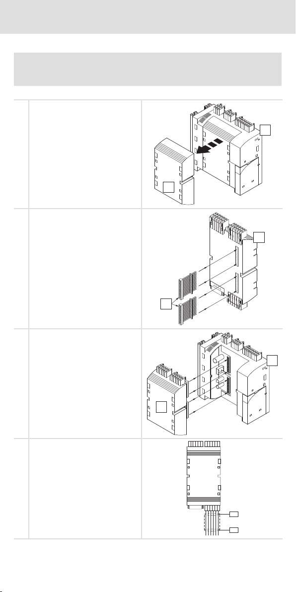
Remove the protection cover from the
Drive PLC [1a] and keep it.
A
Plug the plug connectors onto the
Extension Board [1b].
B
1a
1b
Connect the Extension Board [1b] to the
Drive PLC [1a].
Assign the terminals of the Extension
Board.
PES: HF shield termination by PE
connection
EDK10203EZ3 DE/EN/FR 4.1
14
1a
1b
PES
PES
Page 15

Electrical installation
Assignment of the terminals
5 Electrical installation
Assignment of the terminals
X2
X1
X3
X4
Terminals Assignment
X1 Digital outputs (X1/O5 ... X1/O8) and digital inputs (X1/I15, X1/I16)
X2
X3 Incremental encoder/counter input (Sub−D connector, 9 pole)
X4 Digital inputs (X4/I9 ... X4/I14)
DC supply voltage (X2/+O24, X2/ ^24)
and analog inputs (X2/A ^, X2/AI4, X2/AI5)
Connection required Possible connection
Drive PLC
Extension board III
Emergency off
Load
Encoder
EDK10203EZ3 DE/EN/FR 4.1
15
Page 16

Electrical installation
Assignment of the terminals
Terminal Signal type Function Technical data Remarks
X1/I15
X1/I16
X1/O5
...
X1/O8
X2/A ^
X2/AI4
X2/AI5
X2/+O24 − DC voltage supply 18 VDC ... 30 VDC Connected via
X2/ ^24
X4/I9
...
X4/I14
Digital
inputs
Digital
outputs
− Reference potential for
Analog
inputs
− GND, reference potential
Digital
inputs
analog signals
for digital outputs
LOW (0 V ... +4 V)
HIGH (+13 V ... +30 V)
Input current: max. 8
mA at 24 V
LOW (0 V ... +4 V)
HIGH (+13 V ... +30 V)
Load capacity: max.
1 A
Input voltage:
−10 V ... +10 V
Resolution:
10 bit + sign
LOW (0 V ... +4 V)
HIGH (+13 V ... +30 V)
Input current: max. 8
mA at 24 V
l Use shielded
cables
l Connect the
screen at both
ends
emergency off at the
Drive PLC
Stop!
ƒ Ensure a sufficient dimensioning of the DC voltage supply, if the loads are
connected to the digital outputs.
ƒ The extension board must exclusively be supplied separately.The internal
supply via the Drive PLC is not permissible.
EDK10203EZ3 DE/EN/FR 4.1
16
Page 17

Connection incremental encoder with HTL level
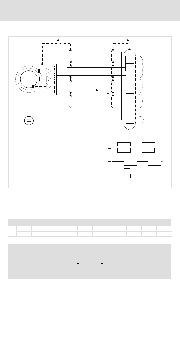
Connection incremental encoder with HTL level
l = max. 50 m
GND
+
-
Electrical installation
B
B
A
A
Z
Z
X3
1
2
Æ
2
mm
0.14 26
AWG
3
4
5
6
7
1.0
0.14
17
8
0.142626
9
A
A
B
B
Z
Z
Incremental encoder with HTL level
Signal flow for CW rotation
Voltage supply for the incremental encoder
Assignment of the Sub−D socket
Pin 1 2 3 4 5 6 7 8 9
X3
Signal B A A +5 V GND Z Z − B
Note!
Incremental encoders with HTL level, which only provide signals A and B, can
be connected to pin 2 (A) and pin 9 (B). The inputs A (pin 3) and B (pin 1) are
then to be connected to the supply voltage of the incremental encoder.
ƒ The connection is to be made as shown in the figure:
– Use cables twisted and shielded in pairs.
– Connect the screen on both ends.
– Observe the cable cross−sections indicated.
EDK10203EZ3 DE/EN/FR 4.1
17
Page 18

Connection incremental encoder with TTL level
Connection incremental encoder with TTL level
Stop!
Observe the connection voltage of the incremental encoder used!
l = max. 50 m
B
B
Electrical installation
V
CC5_E
GND
A
A
Z
Z
X3
1
2
Æ
2
mm
0.14 26
AWG
3
4
5
1.0
17
6
7
0.14 26
8
9
A
A
B
B
Z
Z
Incremental encoder with TTL level
Signal flow for CW rotation
ƒ The incremental encoder can be connected with two 5 V complementary signals
electrically offset by 90 °.
– As option, the zero track can be connected.
Assignment of the Sub−D socket
Pin 1 2 3 4 5 6 7 8 9
X3
Signal B A A V
GND Z Z − B
CC5_E
ƒ The connection is to be made as shown in the figure:
– Use cables twisted and shielded in pairs.
– Connect the screen on both ends.
– Observe the cable cross−sections indicated.
EDK10203EZ3 DE/EN/FR 4.1
18
Page 19

Commissioning
6 Commissioning
Stop!
Before switching on the supply voltage, check the entire wiring concerning
completeness and short circuit.
Switching on:
1. Switch on the supply voltage for Drive PLC and extension board
– The extension board is detected automatically.
2. Load Drive PLC Developer Studio (DDS) project in the Drive PLC
– See documention for DDS and Drive PLC.
3. The additional inputs and outputs are now available for the control. The control is
ready for operation.
Note for Drive PLC with software version as of version 6.1:
The Drive PLC detects automatically
ƒ missing connections to the extension board.
ƒ an extension board which is not compatible with the user program.
ƒ a missing extension board.
Note for Drive PLC with software version before version 6.1:
The Drive PLC does not automatically detect
ƒ missing connections to the extension board.
ƒ an extension board which is not compatible with the user program.
ƒ a missing extension board.
Missing connections, incompatibility or missing extension boards can result in undefined
actions which can endanger the machine/system.
Therefore it is absolutely necessary to ensure that
ƒ the extension board is always connected with both 26−pole plug connectors to the
Drive PLC (see Mounting Instructions of extension board, chapter Mechanical
installation", plug connectors ).
ƒ the extension board type matches the user program.
Note!
ƒ Lenze makes function blocks available to you which can be loaded into
your application program for the Drive PLC. This enables the Drive PLC to
detect missing connections or non−compatible extension boards and to
output an error message.
ƒ The function blocks can be downloaded from the Lenze homepage.
EDK10203EZ3 DE/EN/FR 4.1
19
Page 20

Avant−propos et généralités
Le présent fascicule
0Fig. 0Tab. 0
1 Avant−propos et généralités
Le présent fascicule
ƒ contient les principales caractéristiques techniques de la carte d’extension III et décrit
son installation, sa manipulation et sa mise en service.
ƒ n’est valable que
– pour la carte d’extension III de type EPZ−10203,
– conjointement avec les instructions de montage du Drive PLC.
Description
La carte d’extension III permet une extension de 8 entrées numériques, 4 sorties
numériques, 2 entrées analogiques et 1 entrée codeur incrémental/compteur.
Domaine d’utilisation
Utilisation possible avec les Drive PLC type EPL−10200−EI
Accessoires
L’emballage comprend les composants suivants :
– 2 connecteurs à broches (2 x 13 broches chacun) (déjà montés pour EPL−10203−EI),
– un bornier à 6 bornes pour les entrées numériques (I9 ... I14),
– un bornier à 6 bornes pour les sorties numériques (05 ... 08),
et les entrées numériques (I15, I16),
– un bornier à 6 bornes pour la tension de sortie (+024, ^24)
et les entrées analogiques (A ^, AI4, AI5).
EDK10203EZ3 DE/EN/FR 4.1
20
Page 21

Consignes de sécurité
Consignes utilisées
2 Consignes de sécurité
Consignes utilisées
Pour indiquer des risques et des informations importantes, la présente documentation
utilise les mots et symboles suivants :
Consignes de sécurité
Présentation des consignes de sécurité
Danger !
(Le pictogramme indique le type de risque.)
Explication
(L’explication décrit le risque et les moyens de l’éviter.)
Pictogramme et mot associé Explication
Situation dangereuse pour les personnes en raison d’une
tension électrique élevée
Danger !
Danger !
Stop !
Consignes d’utilisation
Pictogramme et mot associé Explication
Indication d’un danger imminent qui peut avoir pour
conséquences des blessures mortelles ou très graves en
cas de non−respect des consignes de sécurité
correspondantes
Situation dangereuse pour les personnes en raison d’un
danger d’ordre général
Indication d’un danger imminent qui peut avoir pour
conséquences des blessures mortelles ou très graves en
cas de non−respect des consignes de sécurité
correspondantes
Risques de dégâts matériels
Indication d’un risque potentiel qui peut avoir pour
conséquences des dégâts matériels en cas de non−respect
des consignes de sécurité correspondantes
Remarque
importante !
Conseil !
EDK10203EZ3 DE/EN/FR 4.1
Remarque importante pour assurer un fonctionnement
correct
Conseil utile pour faciliter la mise en oeuvre
Référence à une autre documentation
21
Page 22

Caractéristiques générales et conditions d’utilisation
Spécifications techniques
3 Spécifications techniques
Caractéristiques générales et conditions d’utilisation
Conformité CE Directive Basse Tension (2006/95/CE)
Homologations UL 508C Underwriter Laboratories (File−No. E132659)
Alimentation CC
Humidité admissible Classe 3K3 selon EN 50178
Plages de température
Réduction de puissance des courants de sortie pour ta > +40 °C : 2,5 %/K
Résistance aux
chocs/vibrations
Position de montage
admissible
Tension d’isolement potentiel
de terre/PE
Indice de protection IP 20
Entrées numériques
Sorties numériques
Entrées analogiques
Entrée codeur incrémental/
compteur
Encombrements
Hauteur 145 mm (borniers compris)
Largeur 72 mm
Profondeur35 mm
Tension +18 VCC −0 % ... +30 VCC +0 % externe
Courant 4A maxi
(sans condensation, humidité relative moyenne 85 %)
Transport −25 °C ...+70 °C
Stockage −25 °C ...+60 °C
Fonctionnement 0 °C ... +40 °C sans réduction de puissance
Résistance à l’accélération jusqu’à 0,7 g
A l’intérieur du Drive PLC, dans l’emplacement prévu pour la carte
d’extension
50 V CA
Niveau BAS (0 V ...+4 V)
Courant
d’entrée
Niveau BAS (0 V ...+4 V)
Charge
admissible
Tension d’entrée −10 V ... +10 V
Résolution 10 bits + signe
Raccordement Prise Sub−D 9 broches
Niveau HTL Fréquence d’entrée : 0 − 200 kHz
Niveau TTL Fréquence d’entrée : 0 − 500 kHz
Power Conversion Equipment
(avec charge maxi sur toutes les sorties)
+40 °C ... +55 °C avec réduction de puissance
HAUT (+13 V ...+30 V)
8 mA pour 24 V
HAUT (+13 V ...+30 V)
1 A maxi par sortie
Consommation maxi par canal : 5 mA
Consommation maxi par canal : 6 mA
Consommation maxi sur broche Pin 4 (V
150 mA
CC5_E
) :
EDK10203EZ3 DE/EN/FR 4.1
22
Page 23

Installation mécanique
4 Installation mécanique
Stop !
Pendant l’installation, couper la tension d’alimentation du Drive PLC !
Enlever le capot de protection du Drive
PLC [1a] (le conserver
précieusement).
A
Enficher les connecteurs à broches
dans la carte d’extension [1b].
B
1a
1b
Enficher la carte d’extension [1b] dans le
Drive PLC [1a].
Affecter les bornes de la carte
d’extension.
PES : terminaison blindage HF par
raccordement PE
EDK10203EZ3 DE/EN/FR 4.1
23
1a
1b
PES
PES
Page 24

Installation électrique
Affectation des bornes de raccordement
5 Installation électrique
Affectation des bornes de raccordement
X2
X1
X3
X4
Bornier Affectation
X1 Sorties numériques (X1/O5 ... X1/O8) et entrées numériques (X1/I15, X1/I16)
X2
X3 Entrée codeur incrémental/compteur (prise Sub−D 9 broches)
X4 Entrées numériques (X4/I9 ... X4/I14)
Alimentation courant continu (X2/+O24, X2/ ^24)
et entrées analogiques (X2/A ^, X2/AI4, X2/AI5)
Liaison impérative Liaison possible
Drive PLC
Carte d’extension III
Arrêt d’urgence
Récepteur
Alimentation
EDK10203EZ3 DE/EN/FR 4.1
24
Page 25

Installation électrique
Affectation des bornes de raccordement
Borne Type de
X1/I15
X1/I16
X1/O5
...
X1/O8
X2/A ^
X2/AI4
X2/AI5
X2/+O24 − Alimentation courant
X2/ ^24
X4/I9
...
X4/I14
signal
Entrées
numériques
Sorties
numériques
− Potentiel de référence
Entrées
analogique
s
− GND, potentiel de
Entrées
numériques
Fonction Spécifications
pour signaux analogiques
continu
référence pour sorties
numériques
techniques
BAS (0 V ... +4 V)
HAUT (+13 V ... +30 V)
Courant d’entrée :
8 mA maxi pour 24 V
BAS (0 V ... +4 V)
HAUT (+13 V ... +30 V)
Charge maxi
admissible : 1 A
Tension d’entrée :
−10 V ... +10 V
Résolution :
10 bits + signe
18 VCC ... 30 VCC Coupée via arrêt
BAS (0 V ... +4 V)
HAUT (+13 V ... +30 V)
Courant d’entrée :
8 mA maxi pour 24 V
Stop !
ƒ Lors du raccordement des récepteurs aux sorties numériques, assurer un
dimensionnement suffisant de l’alimentation courant continu.
ƒ Pour la carte d’extension, prévoir impérativement une alimentation
externe. L’alimentation interne via Drive PLC n’est pas admise.
Remarque
l Utiliser des
câbles blindés.
l Raccorder le
blindage aux
deux extrémités.
d’urgence sur le PLC
EDK10203EZ3 DE/EN/FR 4.1
25
Page 26

Installation électrique
Raccordement du codeur incrémental HTL
Raccordement du codeur incrémental HTL
l = max. 50 m
+
-
GND
B
B
A
A
Z
Z
X3
1
2
Æ
2
mm
0.14 26
AWG
3
4
5
6
7
1.0
0.14
17
8
0.142626
9
A
A
B
B
Z
Z
Codeur incrémental HTL
Evolution des signaux pour rotation en sens horaire
Tension d’alimentation pour le codeur incrémental
Affectation de la prise Sub−D
Broche 1 2 3 4 5 6 7 8 9
X3
Signal B A A +5 V GND Z Z − B
Remarque importante !
Les codeurs incrémentaux HTL ne fournissant que les signaux A et B peuvent
être raccordés aux broches 2 (A) et 9 (B). Dans ce cas, affecter la tension
d’alimentation du codeur incrémental aux entrées A (broche 3) et B (broche 1).
ƒ Procéder au raccordement comme l’indiquent les schémas.
– Utiliser des câbles en paires torsadées et blindées.
– Raccorder le blindage des deux extrémités.
– Respecter les sections prescrites.
EDK10203EZ3 DE/EN/FR 4.1
26
Page 27

Installation électrique
Raccordement du codeur incrémental TTL
Raccordement du codeur incrémental TTL
Stop !
Tenir compte de l’alimentation du codeur incrémental utilisé !
l = max. 50 m
V
GND
B
B
A
A
CC5_E
Z
Z
X3
1
2
Æ
2
mm
0.14 26
AWG
3
4
5
1.0
17
6
7
0.14 26
8
9
A
A
B
B
Z
Z
Codeur incrémental TTL
Evolution des signaux pour rotation en sens horaire
ƒ Le codeur incrémental peut être raccordé avec 2 signaux complémentés 5V décalés
de 90°.
– Le top zéro peut être connecté (option).
Affectation de la prise Sub−D
Broche 1 2 3 4 5 6 7 8 9
X3
Signal B A A V
GND Z Z − B
CC5_E
ƒ Procéder au raccordement comme l’indiquent les schémas.
– Utiliser des câbles en paires torsadées et blindées.
– Raccorder le blindage des deux extrémités.
– Respecter les sections prescrites.
EDK10203EZ3 DE/EN/FR 4.1
27
Page 28

Mise en service
6 Mise en service
Stop !
Avant la mise sous tension, vérifier le câblage dans son intégralité et les
court−circuits éventuels.
Mise en service
1. Mettre le Drive PLC et la carte d’extension sous tension.
– La carte d’extension est détectée automatiquement.
2. Charger le projet Drive PLC Developer Studio (DDS) dans le Drive PLC.
– Voir documentation concernant DDS et Drive PLC.
3. Les entrées et sorties supplémentaires peuvent maintenant être activées. La
commande est prête à fonctionner.
Remarque importante relative au Drive PLC à partir de la version 6.1. :
Le Drive PLC détecte automatiquement
ƒ les liaisons erronées avec la carte d’extension.
ƒ les problèmes de compatibilité entre le programme d’application et la carte
d’extension.
ƒ l’absence de la carte d’extension.
Remarque importante relative au Drive PLC jusqu’à la version 6.1 :
Le Drive PLC ne détecte pas automatiquement
ƒ les liaisons erronées avec la carte d’extension.
ƒ les problèmes de compatibilité entre le programme d’application et la carte
d’extension.
ƒ l’absence de la carte d’extension.
Les liaisons erronées, les problèmes de compatibilité ou l’absence des cartes d’extension
peuvent entraîner des réactions non définies dans le programme d’application,
susceptibles d’être dommageables pour la machine/l’installation.
Par conséquent, avant la mise en service d’un Drive PLC avec carte d’extension, s’assurer que
ƒ la carte d’extension est toujours reliée au Drive PLC via les deux connecteurs mâles
26 broches (voir les instructions de montage de la carte d’extension, chapitre
Installation mécanique", connecteurs à broches ).
ƒ le type de carte d’extension utilisé est compatible avec le programme d’application.
Remarque importante !
ƒ Lenze met à votre disposition des blocs fonction que vous pouvez charger
dans le programme d’application du Drive PLC. Le Drive PLC est alors en
mesure de détecter les liaisons erronées ou les problèmes de compatibilité
avec les cartes d’extension et, le cas échéant, émettra un message d’erreur.
ƒ Ces blocs fonction peuvent être téléchargés depuis la page d’accueil de
Lenze.
EDK10203EZ3 DE/EN/FR 4.1
28
Page 29

© 08/2010
Lenze Automation GmbH
F
Hans−Lenze−Str. 1
D−31855 Aerzen
Germany
(
+49(0)51 54 /82−0
Ê
+49(0)51 54 /82 − 28 00
Lenze@Lenze.de
ü
www.Lenze.com
Service Lenze Service GmbH
Breslauer Straße 3
D−32699 Extertal
Germany
(
008000/ 2446877 (24 h helpline)
Ê
+49(0)5154/ 82−11 12
Service@Lenze.de
EDK10203EZ3 § .=r+ § DE/EN/FR § 4.1 § TD00
10987654321
 Loading...