

Page 1
EDSLCMX3024-SPS
.4%j
Ä.4%jä
L-force Drives
Hardware Manual
LCU 0.75 ... 3 kW
ELCAMWIxxx4SNNPSNN (LCU121), ELCAMZIxxx4SNNPSNN (LCU122)
Decentralised motor starters
Page 2
This documentation is valid for ...
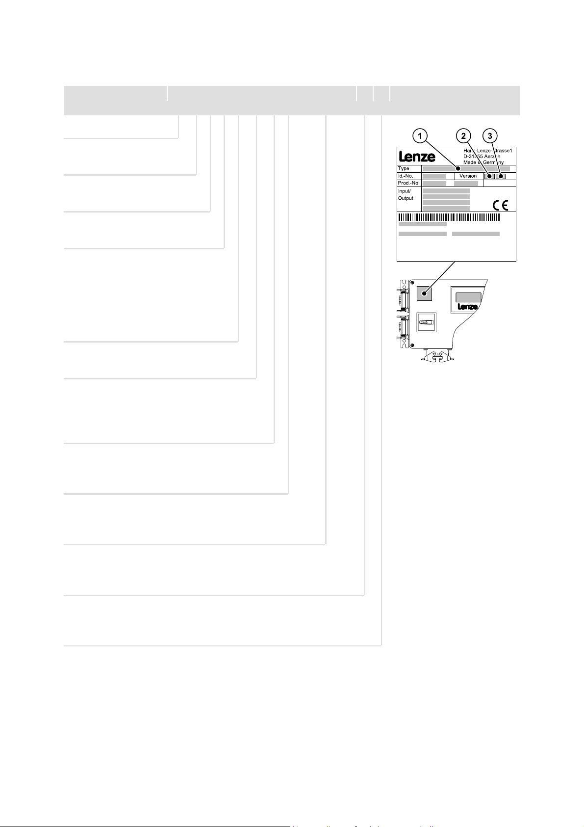
... ELCAM... motor starters as of nameplate designation:
c d e Nameplate
ELC A M x I xxx x S NN PS NN 1B 20
Product series
LCU
Version
A= 1st generation
Type
M= motor starter
Variant
E= one motor, one direction of
rotation
Z = two motors, one direction of
rotation
W = one motor, two directions of
rotation
Mechanical version
I= housing in high enclosure IP54
Rated power [W]
e.g.
75 x 10
15 x 10
1
W = 750 W
2
W=1.5kW
751 =
152 =
Voltage class
2= 230 V AC
4 = 400 V AC
Safety function
A= without safety functions
S= withdrive-basedsafety
Communication
PM = PROFIBUS-DP-V0
PS = PROFIBUS-DP-V0, PROFIBUS-DP-V1, PROFIsafe
Hardware version
Px = prototype, version x
1C = series, version C
lcu12x_002
Software version
12 = software 1.2
22 = software 2.2
Page 3

Document history
Material number Version Description
-1.005/2005 TD00 Preliminary version
13131793 3.0 04/2006 TD00 Complete revision for series-production version
Revision of chapter ”Safety engineering”
13140447 4.0 05/2006 TD00 Revision of chapter ”Technical data”
.4%j 5.0 01/2007 TD19 New functions of SW 3.4 added:
Chapter ”Electrical installation”
Chapter ”Commissioning”
0Fig.0Tab. 0
Tip!
Current documentation and software updates concerning Lenze products can be found
on the Internet in the ”Services & Downloads” area under
http://www.Lenze.com
© 2007 Lenze Drive Systems GmbH, Hans-Lenze-Straße 1, D-31855 Aerzen
No part of this documentation may be reproduced or made accessible to third parties without written consent by Lenze Drive
Systems GmbH.
All information given in this documentation has been selected carefully and complies with the hardware and software
described. Nevertheless, discrepancies cannot be ruled out. We do not take any responsibility or liability for any damage that
may occur. Necessary corrections will be included in subsequent editions.
Page 4

Contentsi
1 Safety instructions 7.........................................................
1.1 General safety and application notes for Lenze motor starters 7...............
1.2 Residual hazards 9.....................................................
1.3 Definition of notes used 10...............................................
2 Device description 11........................................................
2.1 ELCAMWIxxx4SNNPSNN motor starter 11..................................
2.2 ELCAMZIxxx4SNNPSNN motor starter 13...................................
3 Technical data 15............................................................
3.1 General data and operating conditions 15..................................
3.2 Rated data 17..........................................................
4 Mechanical installation 20.....................................................
4.1 Dimensions 20..........................................................
4.2 Mounting clearance 21...................................................
5 Electrical installation 22.......................................................
5.1 Important notes 22......................................................
5.2 Basic circuit d iagram 24..................................................
5.2.1 ELCAMWIxxx4SNNPSNN motor starter 24..........................
5.2.2 ELCAMZIxxx4SNNPSNN motor starter 25...........................
5.3 Mains connection 27....................................................
5.4 Motor connection 28...................................................
5.4.1 ELCAMWIxxx4SNNPSNN motor starter 28..........................
5.4.2 ELCAMZIxxx4SNNPSNN motor starter 29...........................
5.5 Safety engineering 30...................................................
5.6 Control terminals 34.....................................................
5.7 Communication 36......................................................
5.8 Final works 41..........................................................
4
EDSLCMX3024-SPS EN 5.0
Page 5

Contents i
6PROFIsafeonboard 42........................................................
6.1 Technical data 42.......................................................
6.1.1 General data and operating conditions 42..........................
6.1.2 Protective insulation 42..........................................
6.1.3 Communication times 43.........................................
6.2 Establishing of PROFIBUS communication 44................................
6.2.1 Configuration of the host 44......................................
6.2.2 Safe addressing 46..............................................
6.2.3 Addressing 46..................................................
6.3 Process data transfer 47.................................................
6.3.1 Device control 48...............................................
6.4 Parameter data transfer 53...............................................
6.4.1 DRIVECOM parameter data channel (DP-V0, cyclic) 54.................
6.4.2 PROFIdrive parameter data channel (DP-V1, acyclic) 62................
6.4.3 PROFIdrive parameter data channel (PCW) 77........................
6.4.4 Parameter set transfer 82.........................................
6.5 Commissioning 83......................................................
6.6 Code table 84..........................................................
6.6.1 Communication-relevant Lenze codes 86............................
6.6.2 Monitoring 91..................................................
6.6.3 Diagnostics 93..................................................
6.7 Appendix 102...........................................................
6.7.1 Special characteristics for the use of Lenze standard devices 102.........
6.7.2 Consistent parameter data 102.....................................
7 Safety engineering 104........................................................
7.1 Basics 104..............................................................
7.1.1 Introduction 104.................................................
7.1.2 Drive-based safety with L-force | LCU 104............................
7.1.3 Terms and abbreviations of the safety engineering 105.................
7.1.4 Safety instructions 106............................................
7.1.5 Hazard and risk analysis 108.......................................
7.1.6 Standards 108...................................................
7.1.7 Overview of sensors 109...........................................
7.2 Test certificate 110.......................................................
7.3 Display elements 111.....................................................
7.4 Safe inputs and safe outputs 112...........................................
7.4.1 Overview 112....................................................
7.4.2 Technical data 113...............................................
7.4.3 Safe inputs 114..................................................
7.4.4 Safe outputs 118.................................................
7.4.5 Connection plans 119.............................................
EDSLCMX3024-SPS EN 5.0
5
Page 6

Contentsi
7.5 Safety functions 120......................................................
7.5.1 Function mode 120...............................................
7.5.2 Description 121..................................................
7.5.3 Error states 122..................................................
7.5.4 Safe torque off 123...............................................
7.5.5 Safe PROFIsafe connection 125.....................................
7.6 Commissioning 135......................................................
7.7 Acceptance 136..........................................................
7.7.1 Description 136..................................................
7.7.2 Periodic inspections 137...........................................
8 Commissioning 138...........................................................
8.1 Preconditions 138........................................................
8.1.1 The E82ZBB diagnosis terminal 138.................................
8.1.2 Configuration of the host 140......................................
8.2 Before switching on 141..................................................
8.3 Switch-on sequence 142..................................................
8.4 Switching over between normal operation and reversing operation 143..........
8.5 Code table 144..........................................................
9 Troubleshooting and fault elimination 158.......................................
9.1 Status display 158.......................................................
9.2 Malfunction of the drive 162...............................................
9.3 Fault messages 163......................................................
6
EDSLCMX3024-SPS EN 5.0
Page 7

Safety instructions
General safety and application notes for Lenze motor starters
1 Safety instructions
1.1 General safety and application notes for Lenze motor starters
(according to Low-Voltage Directive 73/23/EEC)
General
Lenze motor starters - according to their enclosure - can have live, and also moving or
rotating parts during operation. Surfaces can be hot.
Non-authorised removal of the required cover, inappropriate use, incorrect installation or
operation create the risk of severe injury to persons or damage to material assets.
More information can be obtained from the documentation.
All operations concerning transport, installation, and commissioning as well as
maintenance must be carriedout byqualified, skilled personnel(IEC 364/CENELEC HD 384
or DIN VDE 0100 and IEC report 664 or DIN VDE 0110 and national regulations for the
prevention of accidents must be observed).
1
According to this basic safety information qualified, skilled personnel are persons who are
familiar with the assembly, installation, commissioning, and operation of the product and
who have the qualifications necessary for their occupation.
Application as directed
Motor starters are components intended for the installation in electrical systems or
machines. They are nothousehold appliances,but are designed as componentsexclusively
for application for commercial or professional use in accordance with EN 61000-3-2. The
documentation contains notes concerning the compliance with the limit values in
accordance with EN 61000-3-2.
When installing the motor starters into machines, commissioning (i.e. starting of
operation as directed) is prohibited until it is proven that the machine corresponds to the
regulations of the EC Directive 98/37/EC (Machinery Directive); EN 60204 must be
observed.
Commissioning (i.e. starting of operation as directed) is only allowed when there is
compliance with the EMC Directive (89/336/EEC).
The motor starters comply with the requirements of Low-Voltage Directive 73/23/EEC.
The harmonised standards of the E N 60947-4-2/DIN VDE 0660 series are applied to the
motor starters.
The technical data as well as the connection conditions can be obtained from the
nameplate and the documentation. They must be strictly observed.
Warning: The motor starters are products with a limited availability in accordance with
EN 60947-4-2/DIN VDE 0660. These products c an cause radio interferences in residential
areas. In this case, the operator may be required to implement corresponding measures.
EDSLCMX3024-SPS EN 5.0
7
Page 8

1
Safety instructions
General safety and application notes for Lenze motor starters
Transport, storage
Please observe the notes on transport, storage and appropriate handling.
Observe the climatic conditions in accordance with EN 60947-4-2/DIN VDE 0660.
Installation
The motor starters must be installed and cooled according to the instructions given in the
corresponding documentation.
Ensure proper handling and avoid mechanical stress. Do not bend any components and do
not change any insulation distances during transport or handling. Do not touch any
electronic components and contacts.
Motor starters contain electrostatically sensitive components, which can easily be
damaged by inappropriate handling. Do not damage or destroy any electrical components
since this might endanger your health!
Electrical connection
When working on live m otor starters, the valid national regulations for the prevention of
accidents (e.g. VBG 4) must be observed.
The electrical installation must be carried out according to the appropriate regulations
(e.g. cable cross-sections, fuses, PE connection). Additional information can be obtained
from the documentation.
Notes about installation according to EMC regulations (shielding, earthing, filters and
cable routing) are included in the documentation. These notes also apply to CE-marked
motor starters. The compliance with limit values required by the EMC legislation is the
responsibility of the manufacturer of the machine or system.
Operation
If necessary, systems including motor starters must be equipped with additional
monitoring and protection devices according to the valid safety regulations (e.g. law on
technical equipment, regulations for the prevention of accidents). The motor starters can
be adaptedto your application. Please observe the corresponding information givenin the
documentation.
All protection covers and doors must be shut during operation.
Note for UL-approved systems with integrated motor starters: UL warnings are notes that
only apply to UL systems. The documentation contains special UL notes.
Maintenance and servicing
The motor starters do not require any maintenance if the prescribed conditions of
operation are observed.
Disposal
Recycle metal and plastic materials. Ensure professional disposal of assembled PCBs.
Observe the product-specific safety and application notes given in these instructions!
8
EDSLCMX3024-SPS EN 5.0
Page 9

1.2 Residual hazards
Protection of persons
ƒ The X2x power connector contacts can conduct hazardous voltages if the motor
starter is connected to the mains. Therefore, disconnect the motor starter before
carryingoutanyworkonit.
ƒ The X2x power connector contacts also conduct hazardous voltages when the motor
starter is disabled. Depending on the risk analysis of the machine/system, you may
have to take additional protective measures.
ƒ Operation at ambient temperatures > 40°C:
– The operating temperature of the motor starter housing is > 60°C.
– Depending upon the risk analysis of the machine/system, you may have to use
additional protective covers.
Motor protection
ƒ The connected motor can overheat if
– motors are operated on the motor starter that do not feature temperature
monitoring with PTC thermistor (PTC) or thermal contact (NC contact)
– temperature monitoring with PTC thermistor (PTC) or thermal contact (NC
contact) is not connected to the motor starter
– temperature monitoring is not activated (C0119)
– the set rated motor current for I
2
t monitoring is switched off (C0121)
–I
Safety instructions
Residual hazards
2
t monitoring is not adjusted to the motor (C0120)
1
EDSLCMX3024-SPS EN 5.0
9
Page 10

1
1.3 Definition of notes used
Safety instructions
Definition of notes used
The following pictographs and signal words are used in this documentation to indicate
dangers and important information:
Safety instructions
Structure of safety instructions:
Danger!
(characterises the type and severity of danger)
Note
(describes the danger and gives information about how to prevent dangerous
situations)
Pictograph and signal word Meaning
Danger!
Danger!
Stop!
Danger of personal injury through dangerous electrical voltage.
Reference to an imminent danger that may result in death or serious
personal injury if the corresponding measures are not taken.
Danger of personal injury through a general source of danger.
Reference to an imminent danger that may result in death or serious
personal injury if the corresponding measures are not taken.
Danger of property damage.
Reference to a possible danger t hat may result in property damage if the
corresponding measures are not taken.
Application notes
Pictograph and signal word Meaning
Note!
Tip!
Important note to ensure troublefree operation
Useful tip for simple handling
Reference to another documentation
10
EDSLCMX3024-SPS EN 5.0
Page 11
ELCAMWIxxx4SNNPSNN motor starter
2 Device description
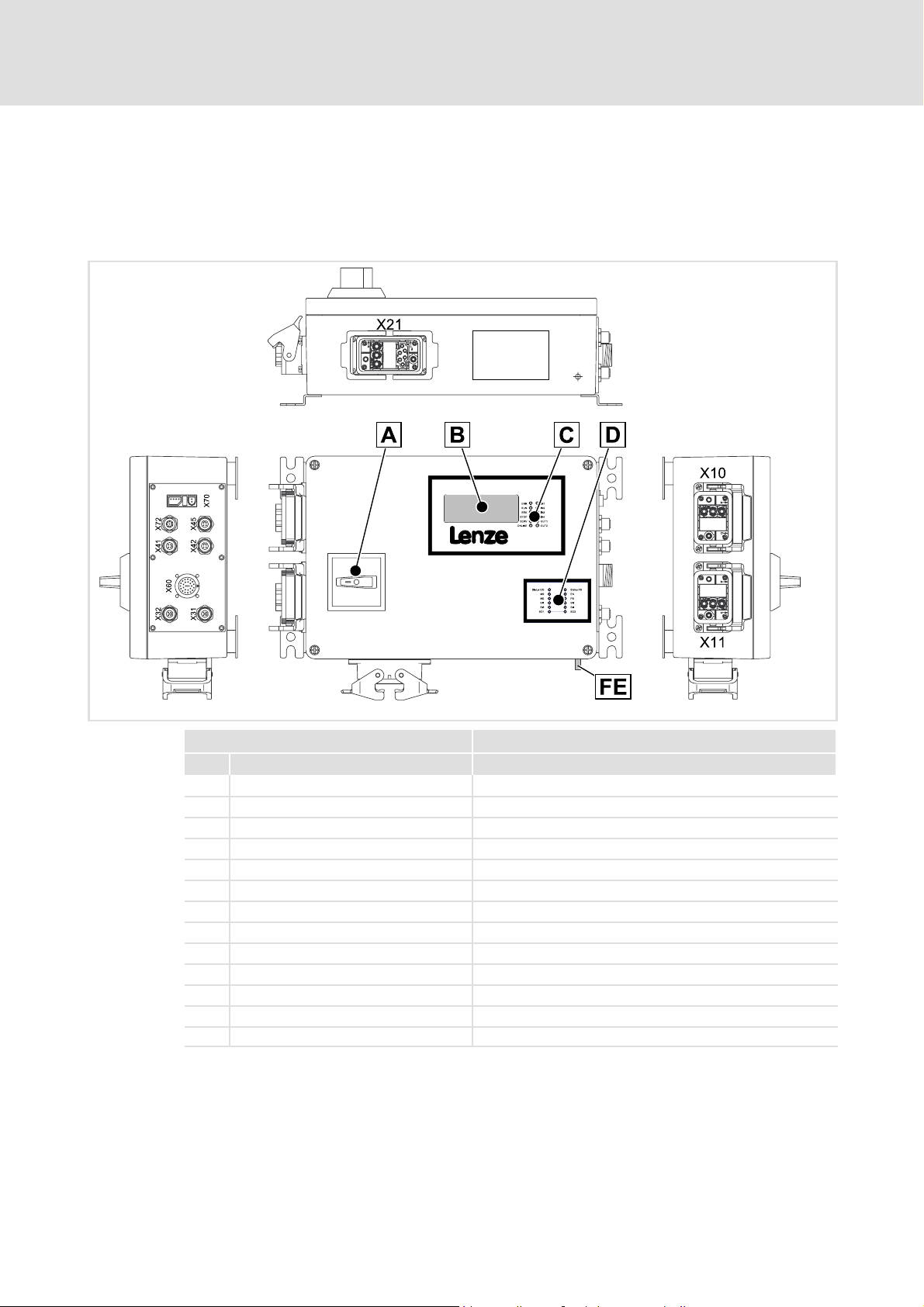
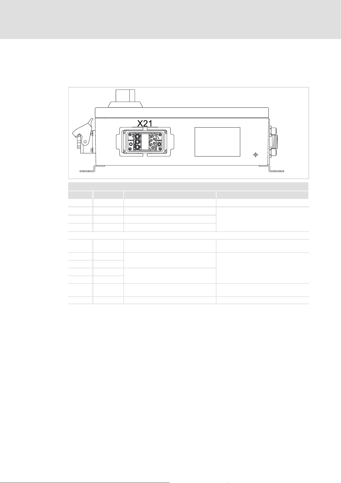
2.1 ELCAMWIxxx4SNNPSNN motor starter
Device description
2
Operational controls and connections
Pos. Function Description
Service switch Triple locking
FE Functional earth M6 threaded bolts
X10 Mains connection Connector: Pins, Harting HAN-Modular
X11 Connection for 24 V supply Connector: Pins, Harting HAN-Modular
X21 Motor 1 connection Connector: Socket, Harting HAN-Modular
X31 PROFIBUS input Connector: Pins, 5-pin, M12, B-coded
X32 PROFIBUS output or bus termination Connector: Socket, 5-pin, M12, B-coded
X41 Digital inputs I1, I2 Connector: Socket, 4-pin, M12
X42 Digital inputs I3, I4 Connector: Socket, 4-pin, M12
X45 Digital outputs Q1, Q2 Connector: Socket, 4-pin, M12
X60 Safe inputs, safe outputs Connector: Socket, 26-pin, M27, N-coded
X70 Diagnostic interface Connector: Plug connector, 4-pin
X721)Manual operation Connector: Socket, 8-pin, M12
1)
Designationinproductionlotwith hardware version PB: X20
lcu121_000A
EDSLCMX3024-SPS EN 5.0
11
Page 12

2
Device description
ELCAMWIxxx4SNNPSNN motor starter
Display elements
Pos. Function
Plain text
display, 4 lines,
20 characters
per line
Status display: device (LED) 159
Status display: fieldbus interface (LED) 160
Status display: drive-based safety (LED) 111
Status ”Operating mode” Status ”Inhibit”
Status ”Motor 1”
”Motor 1 apparent current”
”Error abbreviation” ”Error in plain text”
12
EDSLCMX3024-SPS EN 5.0
Page 13
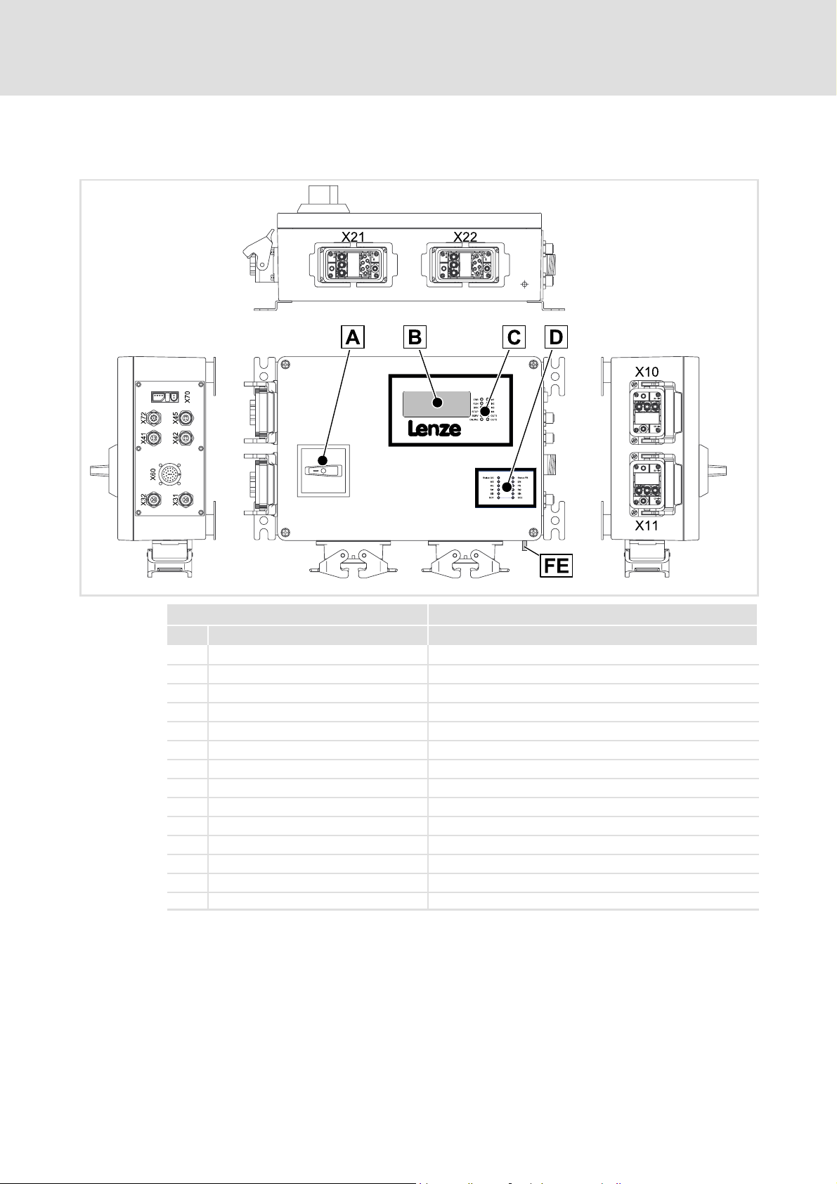
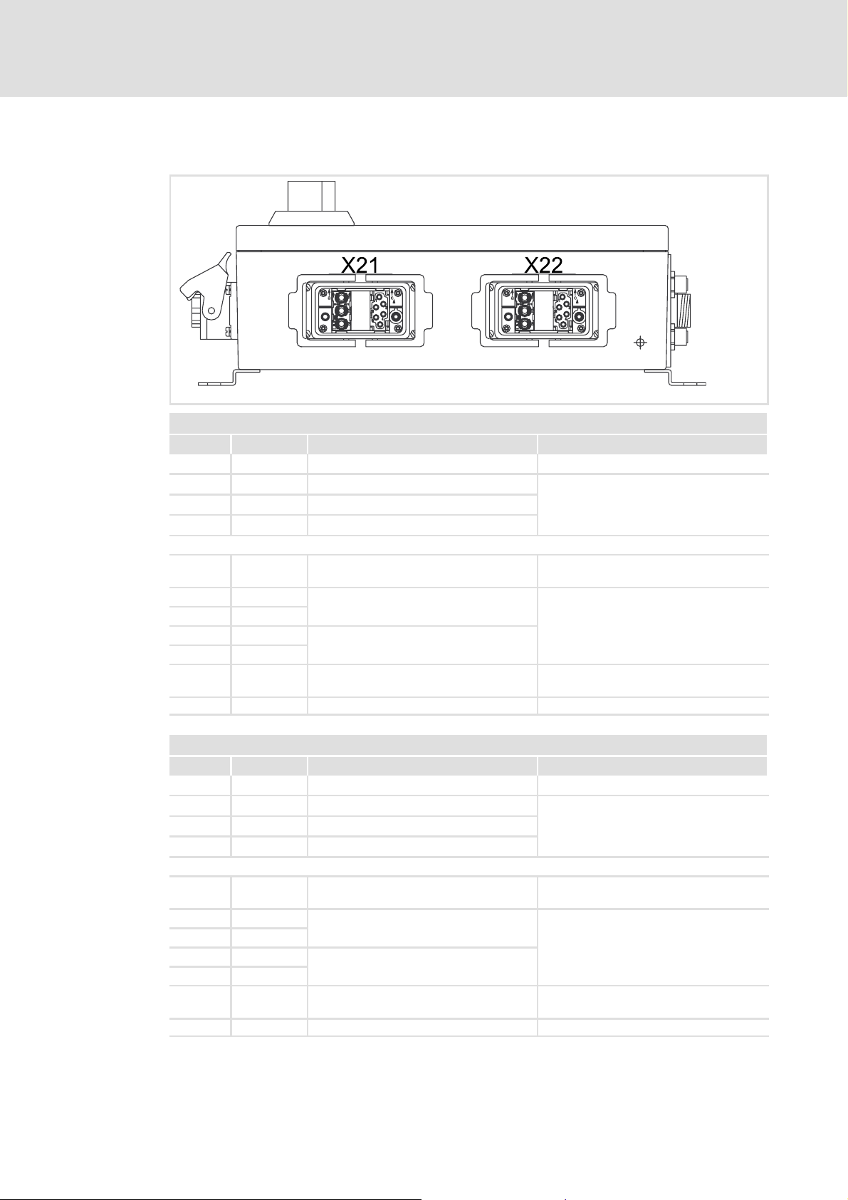
2.2 ELCAMZIxxx4SNNPSNN motor starter
Device description
ELCAMZIxxx4SNNPSNN motor starter
2
Operational controls and connections
Pos. Function Description
Service switch Triple locking
FE Functional earth M6 threaded bolts
X10 Mains connection Connector: Pins, Harting HAN-Modular
X11 Connection for 24 V supply Connector: Pins, Harting HAN-Modular
X21 Motor 1 connection Connector: Socket, Harting HAN-Modular
X22 Motor 2 connection Connector: Socket, Harting HAN-Modular
X31 PROFIBUS input Connector: Pins, 5-pin, M12, B-coded
X32 PROFIBUS output or bus termination Connector: Socket, 5-pin, M12, B-coded
X41 Digital inputs I1, I2 Connector: Socket, 4-pin, M12
X42 Digital inputs I3, I4 Connector: Socket, 4-pin, M12
X45 Digital outputs Q1, Q2 Connector: Socket, 4-pin, M12
X60 Safe inputs, safe outputs Connector: Socket, 26-pin, M27, N-coded
X70 Diagnostic interface Connector: Plug connector, 4-pin
X72 Manual operation Connector: Socket, 8-pin, M12
lcu122_000A
EDSLCMX3024-SPS EN 5.0
13
Page 14

2
Device description
ELCAMZIxxx4SNNPSNN motor starter
Plain text display
Pos. Function
Plain text
display, 4 lines,
20 characters
per line
Status display: device (LED) 159
Status display: fieldbus interface (LED) 160
Status display: drive-based safety (LED) 111
Status ”Operating mode” Status ”Inhibit”
Status ”Motor 1” Status ”Motor 2”
”Motor 1 apparent current” ”Motor 2 apparent current”
”Error abbreviation” ”Error in plain text”
14
EDSLCMX3024-SPS EN 5.0
Page 15

General data and operating conditions
3 Technical data
3.1 General data and operating conditions
General data Values
Conformity CE Low-Voltage Directive (73/23/EEC)
Standards
General technical data Values
EMC Compliance with the requirements in accordance with EN 60947-4-2
Noise emission Compliance with limit class B in accordance with EN 60947-4-2
Leakage current to PE
(according to EN 50178)
Enclosure
Protective measures against Motor overtemperature
Protective insulation of c ontrol
circuits
Insulation resistance Overvoltage category III to VDE 0110
Service switch Rotary switch, triple locking
DIN EN 60947-4-2 Semiconductor motor control units and motor starters for
EN954 KAT3 Safe torque off (STO) according to category 3
<3.5mA
IP 54
NEMA 250 type 4
(input for PTC or thermal contact, I
Safe disconnection from mains:
double/reinforced insulation to EN 50178
reset feedback contact for status message and fault message (TRIP reset)
Technical data
EMC Directive (93/68/EEC)
AC voltage
All connectors that are not used have to be closed by
means of protection covers or blanking plugs.
2
t monitoring)
3
EDSLCMX3024-SPS EN 5.0
15
Page 16

3
Technical data
General data and operating conditions
Operating conditions Values Deviating values
Mechanical tests
Accelerational stability Up to 1 g in accordance with
Vibration resistance In accordance with EN 50178 or
Shock resistance 2m2 in accordance with
Ambient conditions
Climatic conditions
Storage 1k3 in accordance with
Transport 2k3 in accordance with
Operation 3k3 in accordance with
Site altitude 0 ... 4000 m amsl Reduce the rated output current by 5%/1000
Degree of pollution 2 in accordance with VDE 0110 part 2
Mounting location
Mounting positions
vertical Motor plug downwards
horizontal Front cover upwards
Mounting clearances
to the sides
Germanischer Lloyd, general
conditions
EN 60068-2-6
IEC/EN 60721-3-2
IEC/EN 60721-3-1
IEC/EN 60721-3-2
IEC/EN 60721-3-3
21 Theactualfreespaceisdeterminedbythe
above
below
-25 °C ... +70 °C
-10 °C ... +45 °C
m above 1000 m amsl.
connectors used and the cable bending radii.
16
EDSLCMX3024-SPS EN 5.0
Page 17

3.2 Rated data
Motor starter type ELCAMxI 7514SNNPSNN 1524SNNPSNN 2224SNNPSNN 3024SNNPSNN
Supply voltage (safely separated power supply unit SELV/PELV)
Voltage range U
Current consumption at
+24VDC
Motor switch
Mains voltage
(switched voltage)
Cyclic switching Max. 600 switchings / h
Cable protection 16 A, integrated into the housing
Max. motor power
(total power of connected
Lenze motors)
Max. continuous output
current
(sum of the output currents)
Brake switch (AC3 contact)
Output voltage U
Max. output current IB[A] 0.4
Cyclic switching Max. 600 switchings / h
Control connections
Digital inputs 4 (X41, X42)
Digital outputs 2 (X45)
Safe inputs 4 (X60)
Safe outputs 2 (X60)
Manual operation 1 (X72)
Sum of all input currents and
output currents on X41, X42,
X45, X60, X72
Monitoring functions
Motor protection switch I2t monitoring, tripping classes adjustable
Motor temperature PTC thermistor (PTC) or thermal contact (NC contact)
Device protection I2t monitoring class 10A,
Mains failure control Yes
Load failure control Yes, programmable switch-off limit
Mass Approx.
Technical data
Rated data
DC
U
N
PN[kW] 0.75 1.5 2.2 3.0
IN[A] 2.0 3.5 5.0 7.0
B
[A] Max. 1.3
max. Irclass 10A [A] 2.0 3.5 5.0 7.0
max. Irclass 10 [A] 1.7 3.3 4.8 6.5
max. Irclass 20 [A] 1.5 3.0 4.4 6.0
max. Irclass 30 [A] 1.3 2.5 3.8 5.0
[kg]
+ 24 V DC (+20 V DC - 0% ... +26.5 V DC + 0%)
Min. 1 A (no digital inputs and outputs connected)
Max. 5 A (all digital inputs and outputs connected)
3/PE AC 320 V - 0% ... 530 V + 0%; 45 Hz - 0% ... 65 Hz + 0%
= mains voltage
2
t tripping characteristic: 19)
(I
relating to max. continuous output current
5.5 5.5 5.5 5.5
3
EDSLCMX3024-SPS EN 5.0
17
Page 18

3
Technical data
Rated data
Note!
The motor starters are designed for rated currents between 1 A and 7 A.
If motors with rated currents < 1 A are operated on the motor starters, please
observe the following:
ƒ The internal I
– Switch off the internal I
– Use a PTC or thermal contact (NC contact) to monitor the motor
temperature
– Appropriate external motor protection switches can be used in addition.
ƒ The mains phase failure control can respond during operation, although no
main failure has occurred.
– Deactivate the mains phase failure control (C0122 = 3) to ensure that the
drive will not switch off with an error message.
2
xt monitoring cannot be used because of the low current.
2
xt monitoring (C0121 = 0).
18
EDSLCMX3024-SPS EN 5.0
Page 19
Technical data
Rated data
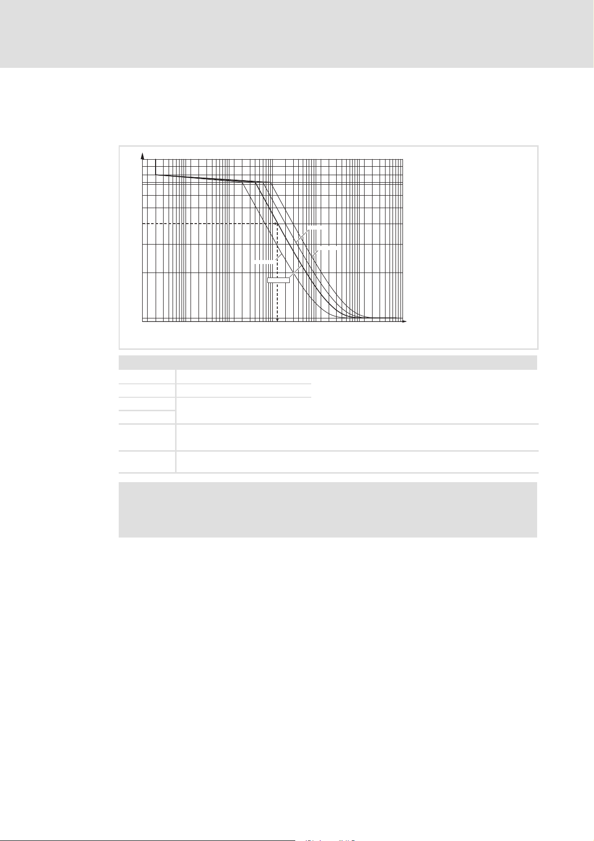
I2t tripping characteristic:
According to DIN EN 60947-4-2 (AC semiconductor motor controllers and starters)
8
7.2
6
5
r
I/I
1.05
4
3
2
0.01 0.1 1 10 100 1000 100000.02
Class 10A
Class 10
t [s]
Class 20
Class 30
3
start031
Tripping classes
Class 10A
Class 10
= Lenze setting
Class 20
Class 30
I = Output current
I
r
Example for
Class 10:
= Rated motor current, can be set in C0120
The motor starter shuts down with an error message, if the output current I measures 4 times
the set rated motor current I
Note!
Regardless of the tripping class set, the motor starter always shuts down if the
output current I measures 8 times the set rated motor current I
Tripping classes, can be set in C0121
for approx. 13 s.
r
for 20 ms.
r
EDSLCMX3024-SPS EN 5.0
19
Page 20
4
Mechanical installation
Dimensions
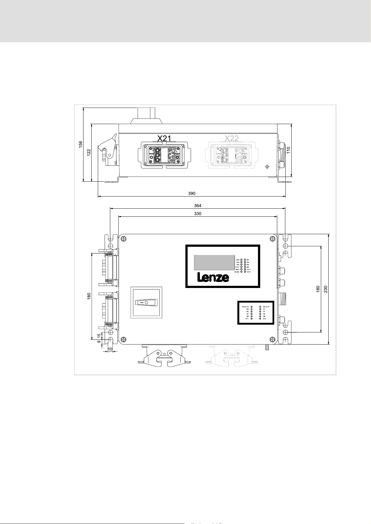
4 Mechanical installation
4.1 Dimensions
20
lcu12x_000b
EDSLCMX3024-SPS EN 5.0
Page 21
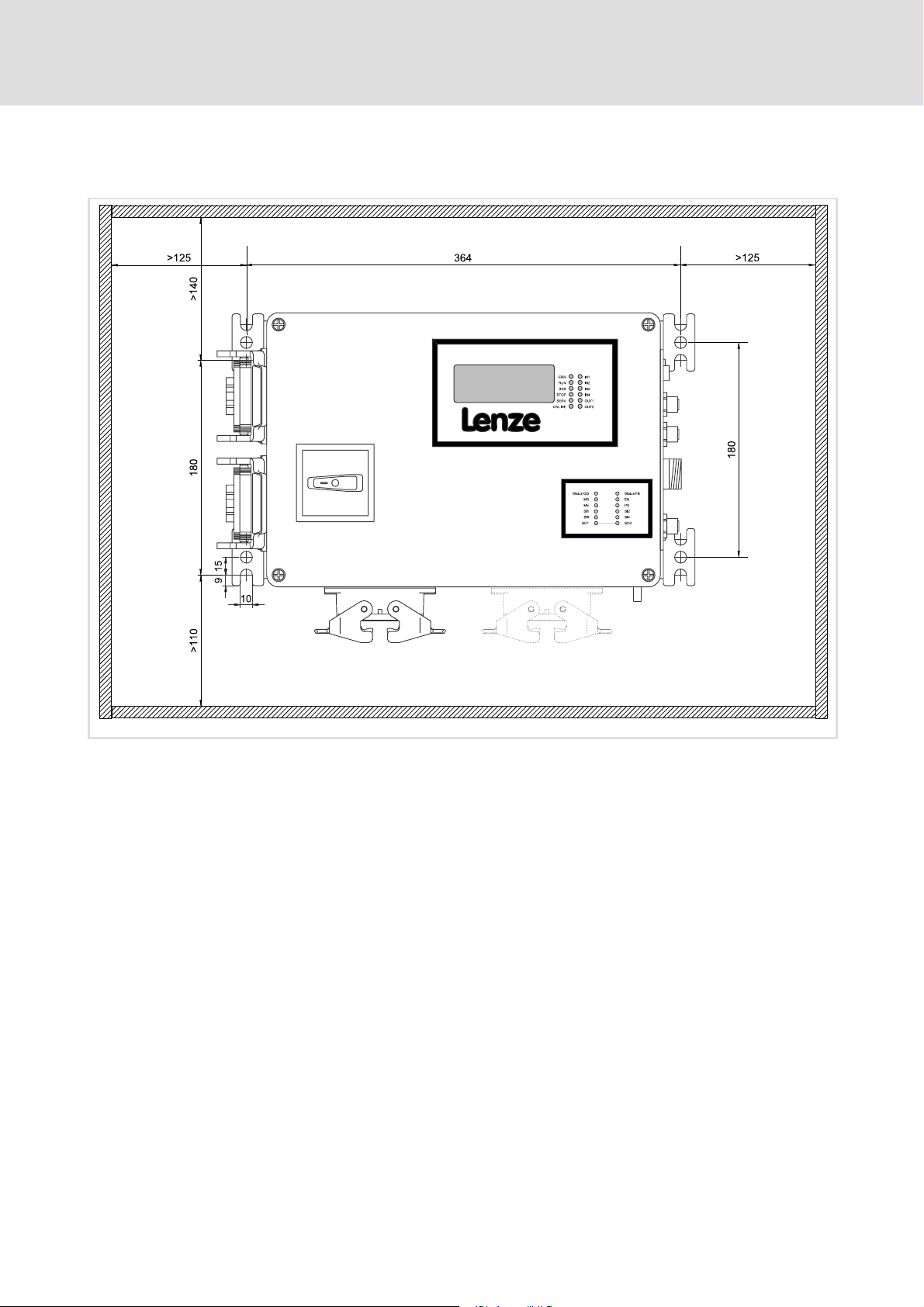
4.2 Mounting clearance
Mechanical installation
Mounting clearance
4
lcu12x_000f
EDSLCMX3024-SPS EN 5.0
21
Page 22

5
Electrical installation
Important notes
5 Electrical installation
5.1 Important notes
Note!
ƒ Please keep the plastic covers on the connectors for the control connections
and interfaces!
ƒ Cover unused connections during transport, storage and operation with the
plastic covers to preserve the certified safety engineering features.
Danger!
ƒ The X2x power connector contacts can conduct hazardous voltages if the
motor starter is connected to the mains. Therefore, disconnect the motor
starter before carrying out any work on it.
ƒ All control terminals feature only basic insulation (single isolating distance)
following the connection of a PTC thermistor (PTC) or a thermal switch (NC
contact):
– Protection against accidental contact with defective isolating distance can
only be ensured through external measures, e.g. double insulation.
ƒ To avoid injury to persons and breakdowns, it is essential that the motor
starter is properly earthed via X10!
Stop!
Ensure trouble-free operation of the motor starter:
ƒ Avoid compensating currents via the PROFIBUS cable shield:
– For this, connect all devices with a 16 mm
– Lay cable in parallel to bus cable.
– Use a copper braid cable to connect the FE bolts with the mounting
surface.
ƒ Properly lock the connector plugs.
2
cableviatheFEbolts.
22
EDSLCMX3024-SPS EN 5.0
Page 23

EMC-compliant wiring
Note!
ƒ Use a copper braid cable to connect the PE bolt with the mounting surface.
ƒ Separate control and data cables from motor cables.
ƒ Connect control and data cable shields at both ends.
Integrated safety engineering
Note!
Please observe during transport, storage and operation:
ƒ Cover unused connectors for control connections and interfaces with the
plastic covers provided to preserve the certified safety technology features.
Electrical installation
Important notes
5
EDSLCMX3024-SPS EN 5.0
23
Page 24
5
Electrical installation
Basic circuit diagram
ELCAMWIxxx4SNNPSNN motor starter
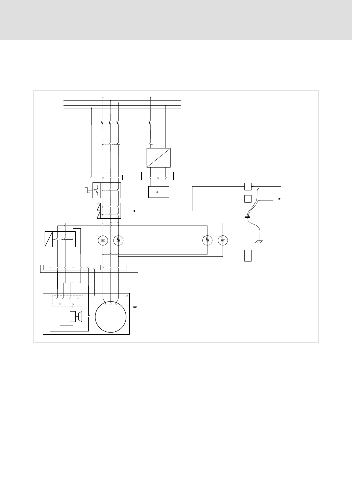
5.2 Basic circuit diagram
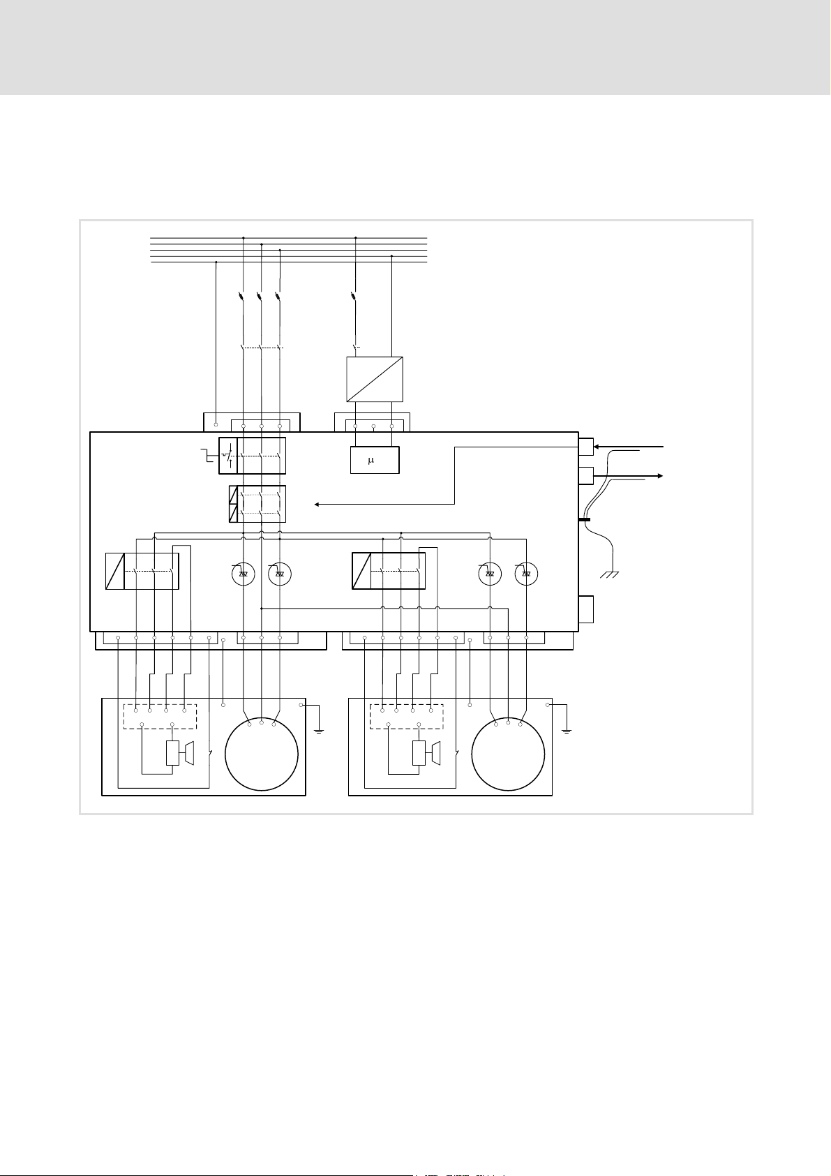
5.2.1 ELCAMWIxxx4SNNPSNN motor starter
BS1
X10
3/PE AC 400 V
PE
a
F1
16 A
K1
4 * 2.5 mm
1
2 3
S0
STO
K2
~
2
X11
24 V DC
-
+
b
1
2 3
C
X31
X32
FE
PROFIsafe
FE
PROFIsafe
FE
X60
L1
L2
L3
N
PE
1 2 3 4 5 6
ca
X21
~ ~ S1 S2
- +
BRK1
1 2 3
PE
PE
V1
U1
Th
M
3~
PE
W1
F1 Cable protection (observe cable protection standards for fuse dimensioning!)
K1 Main contactor
K2 Contactor for 24 V supply
FE Functional earth for compliance with EMC conditions, prevents compensating currents
via the PROFIBUS cable shield
S0 Service switch
BS1 Brake control, motor 1
BRK1 Spring-operated brake, motor 1
Th PTC thermistor (PTC) or thermal contact (NC contact)
STO SafetorqueoffviaPROFIsafe
lcu121_001
24
EDSLCMX3024-SPS EN 5.0
Page 25
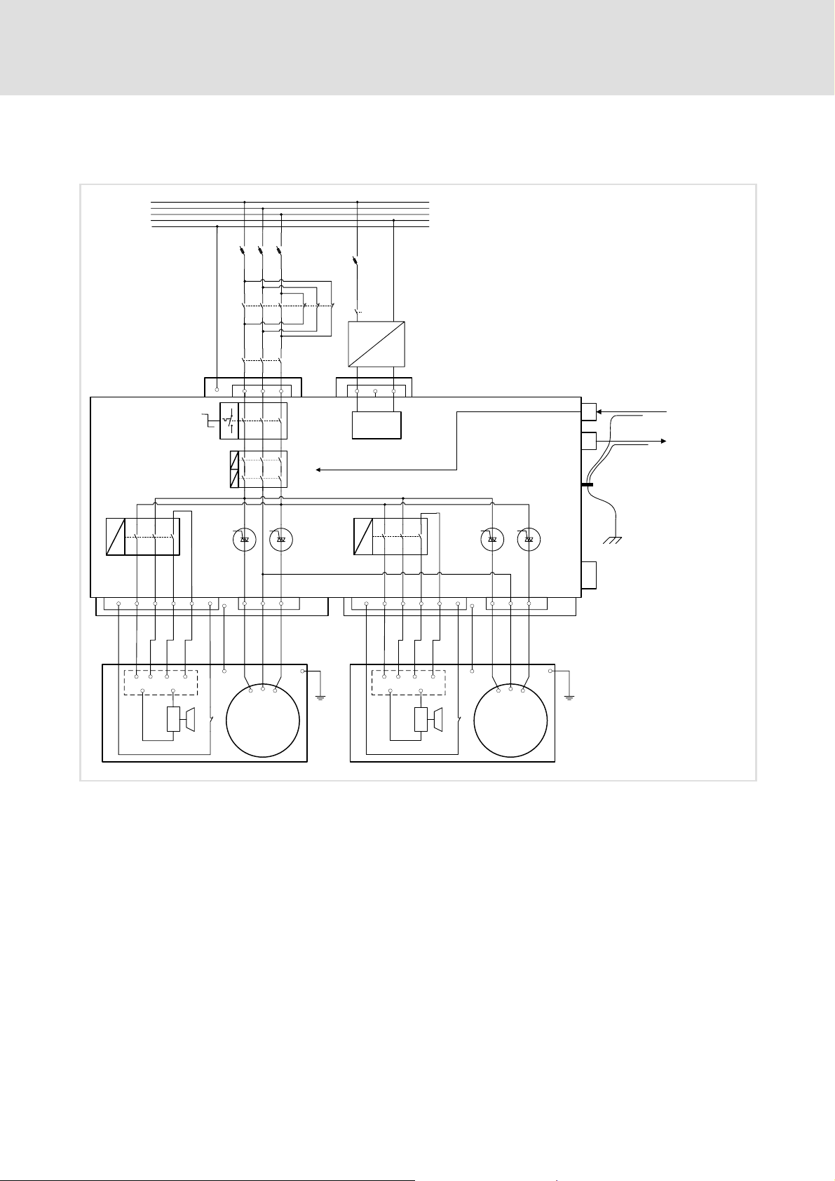
5.2.2 ELCAMZIxxx4SNNPSNN motor starter
Basic circuit diagram for normal operation
Electrical installation
Basic circuit diagram
ELCAMZIxxx4SNNPSNN motor starter
5
BS1
X10
3/PE AC 400 V
PE
a
F1
16 A
K1
4* 2.5 mm
1
2 3
S0
STO
K2
~
2
X11
24 V DC
-
+
b
1
2 3
C
BS2
X31
X32
FE
PROFIsafe
FE
PROFIsafe
FE
X60
L1
L2
L3
N
PE
1 2 3 4 5 6
ca
X21
~ ~ S1 S2
- +
BRK1
1 2 3
PE
PE
V1
U1
Th
M
3~
PE
W1
1 2 3 4 5 6
c
X22
~ ~ S1 S2
- +
BRK2
F1 Cable protection (observe cable protection standards for fuse dimensioning!)
K1 Main contactor
K2 Contactor for 24 V supply
FE Functional earth for compliance with EMC conditions, prevents compensating currents
via the PROFIBUS cable shield
S0 Service switch
BS1 Brake control, motor 1
BRK1 Spring-operated brake, motor 1
BS2 Brake control, motor 2
BRK2 Spring-operated brake, motor 2
Th PTC thermistor (PTC) or thermal contact (NC contact)
STO SafetorqueoffviaPROFIsafe
1 2 3
PE
PE
U1
Th
a
V1
M
3~
PE
W1
lcu122_001
EDSLCMX3024-SPS EN 5.0
25
Page 26
5
Electrical installation
Basic circuit diagram
ELCAMZIxxx4SNNPSNN motor starter
Basic circuit diagram for reversing operation
BS1
2
3/PE AC 400 V
K10
F1
16 A
K2
L1
L2
L3
N
PE
4 * 2.5 mm
~
X10
K1
PE
a
1
2 3
S0
STO
X11
24 V DC
-
+
b
1
2 3
μC
BS2
X31
X32
FE
PROFIsafe
FE
PROFIsafe
FE
X60
1 2 3 4 5 6
ca
X21
~ ~ S1 S2
- +
BRK1
1 2 3
PE
PE
V1
U1
Th
M
3~
PE
W1
1 2 3 4 5 6
c
X22
~ ~ S1 S2
- +
BRK2
F1 Cable protection
Observe cable protection standards for fuse dimensioning!
K1 Main contactor
K10 Contactor relay: Changeover between normal operation and reversing operation
K2 Contactor for 24 V supply
FE Functional earth for compliance with EMC conditions, prevents compensating currents
via the PROFIBUS cable shield
S0 Service switch
BS1 Brake control, motor 1
BRK1 Spring-operated brake, motor 1
BS2 Brake control, motor 2
BRK2 Spring-operated brake, motor 2
Th PTC thermistor (PTC) or thermal contact (NC contact)
STO SafetorqueoffviaPROFIsafe
1 2 3
PE
PE
U1
Th
a
V1
M
3~
PE
W1
lcu122_010
26
EDSLCMX3024-SPS EN 5.0
Page 27

5.3 Mains connection
X10 - Mains connection
Pin Connection Description Data
a1 L1 Phase L1
a2 L2 Phase L3
a3 L3 Phase L3
PE PE conductor
Electrical installation
Mains connection
Connector: Pins, Harting HAN-Modular
3/PE AC 320 V - 0% ... 530 V + 0%
5
lcu12x_000c
X11 - 24 V DC connection
Pin Connection Description Data
Connector: Pins, Harting HAN-Modular
b1 24 V DC Voltage supply for control electronics
b2 n. c. Not assigned
b3 GND Reference potential
Safely separated power supply unit
(SELV/PELV)
+24 V DC
(+20 V DC - 0% ... +26.5 V DC + 0%)
Max. 5 A
EDSLCMX3024-SPS EN 5.0
27
Page 28
5
Electrical installation
Motor connection
ELCAMWIxxx4SNNPSNN motor starter
5.4 Motor connection
5.4.1 ELCAMWIxxx4SNNPSNN motor starter
X21 - Motor 1 connection
Pin Connection Description Data
a1 U1 Phase U1
a2 V1 Phase V1
a3 W1 Phase W1
lcu121_000d
Connector: Socket, Harting HAN-Modular
Output voltage = mains voltage
Max. continuous output current
dependent on type
(sum of all output currents)
c1 +PTC Motor temperature monitoring PTC thermistor (PTC) or thermal contact
c2 ~
c3 ~
c4 S1
c5 S2
c6 -PTC Motor temperature monitoring PTC thermistor (PTC) or thermal contact
PE PE conductor
Brake rectifier supply voltage The brake rectifier is installed in the motor
Switch for disconnection on the DC side
(NC contact)
terminal box
(NC contact)
28
EDSLCMX3024-SPS EN 5.0
Page 29
5.4.2 ELCAMZIxxx4SNNPSNN motor starter
X21 - Motor 1 connection
Pin Connection Description Data
a1 U1 Phase U1
a2 V1 Phase V1
a3 W1 Phase W1
Electrical installation
Motor connection
ELCAMZIxxx4SNNPSNN motor starter
Connector: Socket, Harting HAN-Modular
Output voltage = mains voltage
Max. continuous output current
dependent on type
(sum of all output currents)
5
lcu122_000d
c1 +PTC Motor temperature monitoring PTC thermistor (PTC) or thermal contact
c2 ~
c3 ~
c4 S1
c5 S2
c6 -PTC Motor temperature monitoring PTC thermistor (PTC) or thermal contact
PE PE conductor
X22 - Motor 2 connection
Pin Connection Description Data
a1 U1 Phase U1
a2 V1 Phase V1
a3 W1 Phase W1
c1 +PTC Motor temperature monitoring PTC thermistor (PTC) or thermal contact
c2 ~
c3 ~
c4 S1
c5 S2
c6 -PTC Motor temperature monitoring PTC thermistor (PTC) or thermal contact
PE PE conductor
Brake rectifier supply voltage The brake rectifier is installed in the motor
Switch for disconnection on the DC side
Brake rectifier supply voltage The brake rectifier is installed in the motor
Switch for disconnection on the DC side
(NC contact)
terminal box
(NC contact)
Connector: Socket, Harting HAN-Modular
Output voltage = mains voltage
Max. continuous output current
dependent on type
(sum of all output currents)
(NC contact)
terminal box
(NC contact)
EDSLCMX3024-SPS EN 5.0
29
Page 30

5
5.5 Safety engineering
Electrical installation
Safety engineering
Please observe the following safety instructions and application notes to preserve the
certified safety engineering features and to ensure trouble-free and safe operation.
Danger!
Danger to life through improper installation
Improper installation of the safety engineering systems can cause an
uncontrolled restart of the drives.
Possible consequences:
ƒ Death or severe injuries
Protective measures:
ƒ Safety engineering systems may only be installed and commissioned by
qualified and skilled personnel.
ƒ All control components (switches, relays, PLC, ...) and the control cabinet
must comply with the requirements of EN 954-1 and ISO 13849-2. This
includes i.a.:
– Switches, relays in IP54 enclosure.
– Control cabinet in IP54 enclosure.
– Please refer to EN 954-1 and ISO 13849-2 for all further requirements.
ƒ It is essential to use insulated wire end ferrules for wiring.
ƒ If safety-relevant cables are installed outside the control cabinet, they have
to be protected, e.g. by means of a cable duct:
– Ensure that there are no short circuits.
– For further measures see ISO 13849-2.
ƒ If an external force acts upon the drive axes, additional brakes are required.
Please observe that hanging loads are subject to the force of gravity!
30
Danger!
Danger to life through improper installation
Improper installation of the safety engineering systems can cause an
uncontrolled restart of the drives.
Possible consequences:
ƒ Death or severe injuries
Protective measures:
Total cable length between X60 and the connected components (e.g. sensors,
devices, etc.) > 3 m:
ƒ It is essential to shield the cable installed between X60 and the connected
components:
– Connect the shield at least to X60 in the connector shell.
– If possible, connect the shield to the connected component as well.
Total cable length between X60 and the connected components (e.g. sensors,
devices, etc.) < 3 m:
ƒ Unshielded wiring is permitted.
EDSLCMX3024-SPS EN 5.0
Page 31

Note!
Please observe during transport, storage and operation:
ƒ Cover unused connectors for control connections and interfaces with the
plastic covers provided to preserve the certified safety technology features.
Note!
The sums of all inputs currents and output currents on X41, X42, X45, X60 and
X72maybemax.1.3A.
If the total current is higher, the device switches off!
Electrical installation
Safety engineering
5
EDSLCMX3024-SPS EN 5.0
31
Page 32

5
Electrical installation
Safety engineering
lcu12x_000e
X60 - Safe inputs, safe outputs
Pin Signal Description Data
Connector: Socket, 26-pin, M27, N-coded
1 O1A Output 1 channel A
2 O1B Output 1 channel B
3 GO Reference potential for O1A and O1B
4 O2A Output 2 channel A
5 O2B Output 2 channel B
6 GO Reference potential for O2A and O2B
7 CLB Clock output, channel B
8 CLA Clock output, channel A
9 GCL Reference potential for CLA and CLB
10 I1A Sensor input 1, channel A
11 I1B Sensor input 1, channel B
12 GI1 Reference potential for I1A and I1B
13 I2A Sensor input 2, channel A
14 I2B Sensor input 2, channel B
15 GI2 Reference potential for I2A and I2B
16 I3A Sensor input 3, channel A
17 I3B Sensor input 3, channel B
18 GI3 Reference potential for I3A and I3B
19 I4A Sensor input 4, channel A
20 I4B Sensor input 4, channel B
21 GI4 Reference potential for I4A and I4B
22 n. c. Not assigned
23 n. c. Not assigned
24 n. c. Not assigned
25 n. c. Not assigned
26 n. c. Not assigned
Only for passive sensors
Only for equivalently switching passive
sensors
Only for equivalently switching passive
sensors
Only for active sensors
Only for active sensors
32
EDSLCMX3024-SPS EN 5.0
Page 33

Electrical installation
Safety engineering
Detail characteristics of the safe inputs and safe outputs
Signal Specification Min. Typ. Max.
I1A, I1B
I2A, I2B
I3A, I3B
I4A, I4B
CLA, CLB
O1A, O1B
O2A, O2B
PLC input, IEC-61131-2, 24 V, type 1
LOW signal [V] -3 0 5
Input current [mA] 15
HIGH signal [V] 15 24 30
Input current [mA] 2 15
Input capacitance [nF] 3.3
Switch-off time (depending on the standard device) [ms] 2 4
Switch-on time [ms] 2 4
Input delay (tolerated test pulse) [ms] 1
PLC output, IEC-61131-2, 24 V DC, 50 mA
Supply voltage of the outputs [V] 18 24 30
LOW signal [V] 0 0.8
HGH signal [V] 17 24 29
Output current [mA] 50
Width of test pulse [μs] 750
Frequency of test pulse [s] 1 1.8 3
Specific resistance of a passive sensor [kΩ] 2
PLC output, IEC-61131-2, 24 V DC, short-circuit-proof
Supply voltage of the outputs [V] 18 24 30
Output voltage for LOW signal [V] 0 0.8
Output voltage for HIGH signal [V] 17 24 29
Output current [mA] 500
Width of test pulse [μs] 750 900
Frequency of test pulse [s] 1 1.8 3
5
EDSLCMX3024-SPS EN 5.0
33
Page 34

5
Electrical installation
Control terminals
5.6 Control terminals
Note!
The sums of all inputs currents and output currents on X41, X42, X45, X60 and
X72maybemax.1.3A.
If the total current is higher, the device switches off!
Digital inputs
X41 - Digital inputs I1, I2
Pin Signal Description Data
Connector: Socket, 4-pin, M12
1 +24 V Supply
2 Sign al 2 I2 HIGH +13 .... 26.5 V DC
3
4
X42 - Digital inputs I3, I4
Pin Signal Description Data
1 +24 V Supply
2 Sign al 2 I4 HIGH +13 .... 26.5 V DC
3
4
GND Reference potential LOW 0...+4V
Signal 1 I1 8mAat24VDC
Connector: Socket, 4-pin, M12
GND Reference potential LOW 0...+4V
Signal 1 I3 8mAat24VDC
lcu12x_000e
34
EDSLCMX3024-SPS EN 5.0
Page 35

Electrical installation
Control terminals
Digital outputs
Note!
If inductive loads are being connected, it is essential to use a spark suppressor
at the digital output.
X45 - Digital outputs O1, O2
Pin Signal Description Data
Connector: Socket, 4-pin, M12
1 +24 V Supply
2 Sign al 1 O1 HIGH UDCat X11
3
4
Diagnostic interface
X70 - Diagnostic interface
Pin Signal Description Data
1 ... 4 Connection for handheld keypad or PC
GND Reference potential LOW 0...+4V
Signal 2 O2 Max. 500 mA
interface
Connector: Plug connector, 4-pin
Connection only possible using a Lenze
system cable E82ZWLxxx
Only use PC interfaces featuring electrical
isolation:
LECOM-A (RS232) EMF2102IBCV004 or
LECOM A/B (RS232/RS485)
EMF2102IBCV001
5
Automatic / manual operation
Note!
Manual operation is only possible if the motor starter is enabled by the safety
PLC!
X721)- Manual operation
Pin Signal Description Data
Connector: Socket, 8-pin, M12
1 +24 V Supply (switch in manual operation)
2 Sign al 1 Input automatic/manual operation
3
4 HI1 Input 1 HIGH CW rotation
5 HI2 Input 2 HIGH CCW rotation
6 ... 8 Reserved
1)
GND Reference potential
Designationinproductionlotwith hardware version PB: X20
HIGH Manual operation
LOW Automatic operation
EDSLCMX3024-SPS EN 5.0
35
Page 36

5
Electrical installation
Communication
5.7 Communication
Stop!
High compensation currents
High compensating currents can flow via the PROFIBUS cable shield.
Possible consequences:
Property damage or operational malfunction
Protective measures:
Avoid compensation currents via the PROFIBUS cable shield:
ƒ Connect all PROFIBUS stations with a 16 mm
ƒ Lay this cable in parallel to the bus cable.
ƒ Use copper braid cable to establish a conductive connection between the FE
bolts and the mounting surface.
2
cableviatheFEbolts.
lcu12x_001j
FE Functional earth for compliance with EMC conditions, prevents compensating currents
16 mm
via the PROFIBUS cable shield
2
equalizing conductor
36
EDSLCMX3024-SPS EN 5.0
Page 37

Electrical installation
X31 - PROFIBUS input
Pin Signal Description Data
Connector: male, 5-pin, M12, B-coded
1 n. c. Not assigned
2 A Data line A
3 n. c. Not assigned
4 B Data line B
5 Shld Shield
PROFIBUS-DP-V1
Max. 12 Mbps
5
Communication
lcu121_000i
X32 - PROFIBUS output
Pin Signal Description Data
Connector: female, 5-pin, M12, B-coded
1 VP +5 V for bus termination
2 A Data line A
3 GND Reference potential for bus termination
4 B Data line B
5 Shld Shield
PROFIBUS-DP-V1
Max. 12 Mbps
Bus termination via separate bus
terminating connector
Note!
Plug the bus terminating connector on the last bus station to ensure
trouble-free operation of the PROFIBUS.
EDSLCMX3024-SPS EN 5.0
37
Page 38

5
Electrical installation
Communication
Basic structure of a PROFIBUS network with RS485 cabling without repeater
1
M
333
SSS
222
< 1200 m
0m
lcu12x_005
No. Element Comment
1Host E.g. PC or PLC with PROFIBUS master interface module
2 Bus cable Adapt baud rate to bus cable length
3 PROFIBUS slave Device with PROFIsafe on board
Note!
If a repeater is used, max. 125 stations can communicate via the PROFIBUS.
Please observe the following when wiring
ƒ Do not change the bus topology, i.e. do not use stubs.
ƒ Observe the notes and wiring regulations in the documentation for the control
system.
ƒ Do not use cables other than s pecified in the specifications. ( 40).
ƒ Plug bus terminating connector on X32 at the last bus station. Ensure that the
PROFIBUS is also terminated at the first bus station (master).
38
EDSLCMX3024-SPS EN 5.0
Page 39

Electrical installation
Communication
Number of bus stations
M
RR
SS S S S
123
Segment Master (M) Slave (S) Repeater (R)
1 1
2
2 - 30 1
3 - 30 1
31
30
-
-
5
2133PFB004
Tip!
Repeaters do not have a station address but in the calculation of the
maximum number of stations they reduce the number of stations by 1 on
each side of the segment.
Repeaters can be used to build up line and tree topologies. In this case, the
maximum total bus system expansion depends on
ƒ the baud rate used
ƒ the number of repeaters used
EDSLCMX3024-SPS EN 5.0
39
Page 40

5
Electrical installation
Communication
Baud rate / bus cable length
Baud rate [kbps] Length [m]
9.6 - 93.75 1200
187.5 1000
500 400
1500 200
3000 - 12000 100
Note!
Ensure that the baud rate depending on the amount of data, cycle time and
number of stations is only selected as high as required for the application.
Specification of the transmission cable
Please follow the specifications of the PROFIBUS user organisation (PUO) for signal cables:
Bus cable specification
Specific resistance 135 - 165 Ω/km,(f=3-20MHz)
Capacitance per unit length ≤ 30 nF/km
Loop resistance < 110 Ω/km
Core diameter >0.64mm
Core cross-section >0.34mm
Cores Double twisted, insulated and shielded
2
40
EDSLCMX3024-SPS EN 5.0
Page 41

5.8 Final works
Note!
Please observe during transport, storage and operation:
ƒ Cover unused connectors for control connections and interfaces with the
Electrical installation
Final works
plastic covers provided to preserve the certified safety technology features.
5
EDSLCMX3024-SPS EN 5.0
41
Page 42

6
PROFIsafe on board
Technical data
General data and operating conditions
6PROFIsafeonboard
6.1 Technical data
6.1.1 General data and operating conditions
Area Values
PNO ID number 0951
Communication profile
(DIN 19245 part 1 and part 3)
Communication medium RS485
Network topology Without repeater: line / with repeaters: line or tree
PROFIBUS station Slave
Baud rate [kbps] 9.6 ... 12000 (automatic recognition)
Process data words (PCD)
(16 bits)
PROFIBUS user data length Parameter data channel (4 words) +
PROFIsafe user data 4words
Max. number of stations Standard:32(=1bussegment)/withrepeaters:125
Max. cable length per bus
segment
hex
z PROFIBUS-DP-V0
z PROFIBUS-DP-V1
z PROFIsafe
1word...10words
process data words (1 ... 10 words)
1200 m (depending on the baud rate and cable type used)
6.1.2 Protective insulation
Protective insulation between bus
and ..........
Power connections Basic insulation
PE Basic insulation
24 V supply Functional insulation
Type of insulation according to EN 61800-5-1
42
EDSLCMX3024-SPS EN 5.0
Page 43

6.1.3 Communication times
Tip!
The communication time is the time between the start of a request and the
arrival of the corresponding response.
The PROFIBUS communication times depend on:
ƒ Processing time in the controller
ƒ Transmission delay time
– Transmission rate (baud rate)
– Telegram length
Processing time in the motor starter
The parameter data and process data are independent of each other.
ƒ Parameter data: approx. 30 ms + 20 ms tolerance
PROFIsafe on board
Technical data
Communication times
6
ƒ Process data: approx. 3 ms + 2 ms tolerance
ƒ PROFIsafe
The PROFIsafe communication time depends on the PROFIsafe cycle time. This time is
defined by the F-CPU. It depends on the F-WD time that is set and on the set cycle time
of the monitoring OB in the control.
ƒ PROFIsafe process data in the motor starter:
– F-input data: max. 14 ms
– F-output data: max. 24 ms
EDSLCMX3024-SPS EN 5.0
43
Page 44

6
PROFIsafe on board
Establishing of PROFIBUS communication
Configuration of the host
6.2 Establishing of PROFIBUS communication
6.2.1 Configuration of the host
Device data base file
By means of the device data base file (GSE file), the PROFIBUS is configured.
Note!
IntheGSEfileyoucanselectthetypeoftheparameterdatachannelused
(DRIVECOM or PROFIdrive) and the number of the process data words.
Settings on the master
In the GSE file ”LENZ0951.GSE” you’ll find the configurations:
Module
Safety (4W) - 4 words with consistency 2words
Drivecom-PAR (cons.) +PCD(nW)
Drivecom-PAR (cons.) +PCD(nWcons) n words with consistency 4+nwords
PCW (cons.) +PCD(nW)
PCW (cons.) +PCD(nWcons) n words with consistency 4+nwords
PCD (nW) Without parameter data channel n words without consistency nwords
PCD (nW cons) Without parameter data channel n words with consistency nwords
nW = 1 word ... 10 words
Parameter data
with consistency
DRIVECOM
PCW
Process data
with/without consistency
n words without consistency 4+nwords
n words without consistency 4+nwords
Occupied
I/O memory
Procedure:
1. Import the GSE file ”LENZ0951.GSE” for the motor starter in the master.
2. Select the ”Safety (4W)” module received in the GSE file and copy (drag & drop) it to
slot 1.
3. Select one of the other modules and copy it to slot 2.
Adaptation of the device controls
Tip!
Use total consistency
ƒ Please note that the processing of consistent data varies between hosts.
This must be considered in the PROFIBUS application program.
ƒ Detailed description of consistency: see appendix
44
EDSLCMX3024-SPS EN 5.0
Page 45

PROFIsafe on board
Establishing of PROFIBUS communication
Configuration of the host
Defining user data length
Theuser datalength is defined during thePROFIBUS initialisationphase. Youcan configure
up to 10 process data words.
Optionally you can activate a parameter data channel. If the parameter data channel is
active, it additionally occupies 4 words of the process input and process output data.
ƒ PIW: process data input word
(process data from the motor starter to the master)
ƒ POW: process data output word
(process data from the master to the motor starter)
The user data lengths for process input data and process output data are identical. The
selection takes place via identification bytes in the configuration software for the
PROFIBUS system.
Parameter data channel Process data channel
Without /
with
Without -
With
Identification / user data length Identification / user data length
z Identification
z Identification: F3
z User data length: 4 words
(word 1 ... word 4)
hex
(243)
– without consistency: 70
– with consistency: F0
z User data length: 1 ... 10 words
(POW/PIW 1 ... POW/PIW 10)
z Identification
– without consistency: 70
– with consistency: F0
z User data length: 1 ... 10 words
(POW/PIW 1 ... POW/PIW 10)
hex
hex
hex
... F9
hex
... F9
... 79
hex
(240 ... 249)
hex
... 79
hex
(240 ... 249)
hex
(112 ... 121)
(112 ... 121)
6
General structure of the identification byte
MSB LSB
7 6 5 4 3 2 1 0
User data length
00 1(byte/word)
...
15 16 (bytes / words)
Input/Output
00 Specific identification format
01 Input
10 Output
11 Input and output
Length/Format
0 Byte
1Word
Consistency
0 Byte or word
1Totallength
EDSLCMX3024-SPS EN 5.0
45
Page 46

6
6.2.2 Safe addressing
6.2.3 Addressing
PROFIsafe on board
Establishing of PROFIBUS communication
Safe addressing
Every slave must be provided with an unambiguous PROFIsafe target address.
The PROFIsafe target address can be set in C1570 via the diagnosis terminal or the PC.
( 90)
Valid address range: 1 ... 65534
To address the motor starters, each station must be allocated an unambiguous address.
The station address in set via code C1509, see ( 86), using the diagnosis terminal or the
PC.
Valid address range: 3 ... 126
46
EDSLCMX3024-SPS EN 5.0
Page 47

6.3 Process data transfer
PROFIBUS transmits different telegram contents between the master computer and the
motor starters:
ƒ Parameter data
ƒ Process data
ƒ PROFIsafe
As indicated in the table, this data is distributed into different communication channels
according to their time-critical response.
Process data
z Process data is transferred via the process data channel.
z Use process data to control the motor starter.
z The master computer has direct access to the process data. In the PLC, for instance, the data is directly
assigned to the I/O area. An exchange between the master drive and the motor starter is required in the
shortest possible time with small amounts of data being transferred cyclically.
z Process data is
– not stored in the motor starter.
– transferred between the host and the motor starters in order to exchange current input and output data
continuously.
z Process data for instance refers to setpoints and actual values.
An exchange between the master drive and the motor starter is required in the shortest possible time with small
amounts of data being transferred cyclically.
PROFIsafe on board
Process data transfer
6
Parameter data
z Parameter data is transferred via the parameter data channel.
z If the parameter data channel is active, it additionally occupies 4 words of input and output process data.
z Observe the notes on code C0003 when saving parameter changes.
z In general, the transfer of parameters is not time-critical.
z Parameter data for instance refers to operating parameters, diagnostics information and motor data.
Tab. 6-1 Distribution of parameter data and process data into different communication channels
EDSLCMX3024-SPS EN 5.0
47
Page 48

6
6.3.1 Device control
6.3.1.1 Configuration of process data
PROFIsafe on board
Process data transfer
Device control
Use the free process data configuration to assign the max. 10 PROFIBUS process data
words to the motor starter process data words. Define the assignments in codes C1511
(process output data) and C1510 (process input data).
Tip!
The ”view” is always from the master.
ƒ The master sends process output data in max. 10 process data output words
(POW) to the bus device.
ƒ The master receives process input data in max. 10 process data input words
(PIW) from the bus device.
48
EDSLCMX3024-SPS EN 5.0
Page 49

6.3.1.2 Process data signals f or motor starters
Configuration of process output data
The assignment of the max. 10 process data output words (POW) of the master to bit
control commands or setpoints of the motor starter can be freely configured via C1511.
ƒ You can set up a freely selectable Lenze device control using the FIF control words
( 50).
Note!
When C1511 is modified, the process output data is automatically inhibited in
order to ensure data consistency.
Use C1512 to reenable individual or all POWs.
Configuration of process output data
Code Subcode Index LENZE setting Data type
C1511 23064d=
1(POW1)
2(POW2)
3(POW3)
4(POW4)
5(POW5)
6(POW6)
7(POW7)
8(POW8)
9(POW9)
10 (POW 10)
5A18
PROFIsafe on board
Process data transfer
1 Control word (FIF-CTRL1)
h
6
Device control
FIX32
Tip!
For the description of the complete code see ( 88)
EDSLCMX3024-SPS EN 5.0
49
Page 50

6
PROFIsafe on board
Process data transfer
Device control
The bit assignments forthe applicable controlword 1 (FIF-CTRL1)can be gatheredfrom the
following table:
FIF control word 1 (FIF-CTRL1)
Bit Assignment
0S1(motor 1 start/stop)
0
1
1 S2 (motor 2 start/stop or selection of direction of rotation)
0
1
2 Brake 1 (control of brake 1)
3 Brake 2 (control of brake 2)
4 Reserved
5 Reserved
6 Reserved
7 Reserved
8 Reserved
9 Controller inhibit (FIF-CTRL1-CINH)
0
1
10 External fault
0
1
11 Fault reset
0=>1 (FIF-CRTL1-TRIP-RESET)
12 Reserved
13 Reserved
14 Reserved
15 Reserved
Stop motor 1
Start motor 1
Stop motor 2 or CCW rotation
Start motor 2 or CW rotation
Enable motor starter
Inhibit motor starter
(FIF-CTRL1-TRIP-SET)
External error active
No fault
Bit change causes trip reset
50
EDSLCMX3024-SPS EN 5.0
Page 51

PROFIsafe on board
Process data transfer
Device control
Configuring the process input data
The assignment of the bit status information or actual values of the motor starter to the
max. 10 process data input words (PIW) of the master can be configured freely.
Configuration of process input data
Code Subcode Index LENZE setting Data type
C1510 23065d=
5A19
1(PIW1)
2(PIW2)
3(PIW3)
4(PIW4)
5(PIW5)
6(PIW6)
7(PIW7)
8(PIW8)
9(PIW9)
10 (PIW 10)
h
1 Status word (FIF-STAT1)
FIX32
6
Tip!
For the description of the complete code see ( 87)
EDSLCMX3024-SPS EN 5.0
51
Page 52

6
PROFIsafe on board
Process data transfer
Device control
The bit assignments for the applicable status words can be gathered from the following
table:
Status word 1 (FIF-STAT1) Status word 2 (FIF-STAT2)
Bit
0 Image of C0417/1 Image of C0418/1
1 Image of C0417/2 Image of C0418/2
2 Image of C0417/3 Image of C0418/3
3 Image of C0417/4 Image of C0418/4
4 Image of C0417/5 Image of C0418/5
5 Image of C0417/6 Image of C0418/6
6 Image of C0417/7 Image of C0418/7
7 Controller inhibit Image of C0418/8
8
9 Image of C0418/10
10 Image of C0418/11
11 Image of C0418/12
Assignment Assignment
01Motor starter enabled
Motor starter inhibted
Bits 11 ... 8
Device status
11 10 9 8
0 0 1 1 Operation inhibited
0 1 1 0 Operation enabled
1 0 0 0 Fault active
1 1 1 1 Communication with standard
device not possible
Image of C0418/9
12 Overtemperature warning Image of C0418/13
01No warning
Housing temperature > +75 °C
13 Image of C0417/14 Image of C0418/14
14 Image of C0417/15 Image of C0418/15
15 Image of C0417/16 Image of C0418/16
Note!
The status words FIF-STAT1 and FIF-STAT2 are freely configurable via the codes
C0417 or C0418.
52
EDSLCMX3024-SPS EN 5.0
Page 53

6.4 Parameter data transfer
The PROFIdrive parameter data channel (DP-V0, cyclic)
ƒ enables parameter setting and diagnostics of the motor starter.
ƒ allows access to Lenze parameters (codes).
ƒ additionally occupies the first 4 words of the input and output words in the master.
ƒ has an identical structure for both directions of transmission.
Parameter data is addressed via codes listed in the code table of the corresponding
Operating Instructions for your controller.
Lenze parameter sets
The motor starter features 4 parameter sets, the parameters of which cannot be directly
addressed via the PROFIdrive parameter data channel (DP-V0, cyclic).
PROFIsafe on board
Parameter data transfer
6
Note!
Parameter changes:
Cyclic writing to codes via the PROFIBUS only is permissible if the automatic
parameter set storage of the motor starter (C0003) is deactivated (value 0).
Process data changes:
No automatic storage
EDSLCMX3024-SPS EN 5.0
53
Page 54

6
PROFIsafe on board
Parameter data transfer
DRIVECOM parameter data channel (DP-V0, cyclic)
6.4.1 DRIVECOM parameter data channel (DP-V0, cyclic)
Addressing of the Lenze parameters
For the DRIVECOM parameter data channel, the parameters of a device are not addressed
directly via Lenze code numbers, but via indexes (byte 3 / byte 4) and subindexes (byte 2).
The Lenze code numbers are converted into indexes via an offset (24575
Addressing of the Lenze codes Example for C0001 (operating mode)
–PROFIBUSindex=
24575 - Lenze code number
–PROFIBUSindex
- Lenze code number
5FFF
hex
hex
=
hex
–PROFIBUSindex=
24575 - 1 = 24574
–PROFIBUSindex
5FFF
hex-1hex
hex
= 5FFE
=
hex
dec
or 5FFF
hex
):
Lenze parameters are mainly represented in the fixed point format, data type integer32
withfour decimal digits.For thisreason, the valueof theparameter orthe value of the code
must be multiplied by 10000 in order to obtain integer values.
This parameter value is entered into the user data (byte 5 - byte 8) of the telegram.
Telegram structure
(overview)
The telegram of the DRIVECOM parameter data channel consists of a total of 8 bytes. The
individual bytes are described in detail on the following pages.
Byte 1 Byte 2 Byte 3 Byte 4 Byte 5 Byte 6 Byte 7 Byte 8
Service Subindex Index
High byte
Index
Low byte
Data 4 /
Error 4
Data 3 /
Error 3
Data 2 /
Error 2
Data 1 /
Error 1
54
EDSLCMX3024-SPS EN 5.0
Page 55

PROFIsafe on board
Parameter data transfer
DRIVECOM parameter data channel (DP-V0, cyclic)
Byte 1: service
Job and response control for the parameter data channel
MTSRQPON
Representation of bits 7 ... 0 in byte 1
Job
MON
Job for the motor starter. The bits are only set by the master.
z 000=nojob
z 001 = read job (reading data from the motor starter)
z 010 = write job (writing data to the motor starter)
6
P
RQ
S
T
Fig.6-1 Byte 1: job and response control
Bit 7 0
(Reserved)
Data length
Data length in bytes 5...8 (data 1...4 / error 1...4)
z 00 = 1 byte
z 01 = 2 bytes
z 10 = 3 bytes
z 11 = 4 bytes
Handshake
Indicates a new job. The master changes this bit for every new job. The motor
starter copies the bit to its response telegram.
Status
Status information from the motor starter to the master when sending the job
confirmation. This bit informs the master whether the job has been carried out
without errors.
z 0 = job completed without fault.
z 1 = job not completed. A fault has occurred. The data in the Data/Error field
is interpreted as an error message.
MuNNMMMN
“1” (read)
(reserved)
“3”(= data length 4 bytes)
Handshake
Status, relevant for response telegram only
Bit 7 0
Fig.6-2 Example of byte 1
EDSLCMX3024-SPS EN 5.0
MuNNMMNM
“2” (write)
(reserved)
“3”(= data length 4 bytes)
Handshake
Status, relevant for response telegram only
55
Page 56

6
PROFIsafe on board
Parameter data transfer
DRIVECOM parameter data channel (DP-V0, cyclic)
Byte 2: subindex
Additional addressing via thesubindex isrequired for thosecodes that have a subcode(see
code table).
Example:
Code C0012 / subcode 2 addresses motor 2 acceleration time
Byte 3 / 4: index
Byte 1 Byte 2 Byte 3 Byte 4 Byte 5 Byte 6 Byte 7 Byte 8
Service Subindex Index
High byte
Index
Low byte
Data 4 /
Error 4
Data 3 /
Error 3
Data 2 /
Error 2
Data 1 /
Error 1
The parameters or the Lenze codes are selected with these two bytes according to the
formula:
Index = 24575 - Lenze code number
Example:
The parameter C0012 (acceleration time) is to be addressed:
24575 - 12 = 24563 = 5 FF3
hex
The entries for this example would be:
ƒ Byte 3: Index high byte = 5F
ƒ Byte 4: Index low byte = F3
hex
hex
Byte 5 - 8:
Parameter value (data) or error information (error)
Byte 1 Byte 2 Byte 3 Byte 4 Byte 5 Byte 6 Byte 7 Byte 8
Service Subindex Index
High byte
Index
Low byte
Data 4 /
Error 4
Data 3 /
Error 3
Data 2 /
Error 2
Data 1 /
Error 1
The status of the (”status”) bit 7 in byte 1 (”service”) determines the meaning of this data
field:
Meaning of bytes 5 - 8 if
bit7=0 bit7=1
Parameter value (data 1 - 4 ) Error information (error 1 - 4) for an invalid access.
56
EDSLCMX3024-SPS EN 5.0
Page 57

PROFIsafe on board
Parameter data transfer
DRIVECOM parameter data channel (DP-V0, cyclic)
Parameter value (data)
Depending on the data format, the length of the parameter value is between 1 to 4 bytes.
Data issaved in the Motorola format, i.e. first the high byte orhigh word, thenthe low byte
or low word.
Byte 5 Byte 6 Byte 7 Byte 8
High byte Low byte High byte Low byte
High word Low word
Double word
Assignment of bytes 5 .. 8 with parameter values of different lengths
Byte 5 Byte 6 Byte 7 Byte 8
Parameter value
(length 1)
Parameter value (length 2) 00 00
Note: Strings or data blocks cannot be transmitted.
00 00 00
Parameter value (length 4)
6
Error messages
The following error messages may appear:
Data 1 Data 2 Data 3 Data 4 Meaning
63
6 5 10 Impermissible job parameter
6 5 11 Invalid subindex
6 5 12 Data length too large
6 5 13 Data length too small
6 6 00 Object is no parameter
6 7 00 Object does not exist
6 8 00 Data types do not correspond
8 0 00 Job cannot be executed
8 0 20 Job cannot be executed at the moment
8 0 21 Not executable because of local control
8 0 22 Not executable because of device status
8 0 30 Out of value range/parameter can only be changed with inhibited
8 0 31 Parameter value too large
8 0 32 Parameter value too small
8 0 33 Subparameter out of value range
8 0 34 Subparameter value too large
8 0 35 Subparameter value too small
8 0 36 Maximum value smaller than minimum value
8 0 41 Communication object cannot be mapped on process data
8 0 42 Process data length exceeded
8 0 43 General collision with other values
Data contents in hexadecimal format
00
00 No right to access
controller
EDSLCMX3024-SPS EN 5.0
57
Page 58

6
PROFIsafe on board
Parameter data transfer
DRIVECOM parameter data channel (DP-V0, cyclic)
6.4.1.1 Programming of read jobs
Step Read job
1. Define user data range of the motor starter, i.e. define the location of the user data in the host system
2. Enter the address of the desired parameter in the field ”Index and subindex“ (PROFIBUS output data).
3. Job = read job. The ”Job/handshake“ bit must be changed (PROFIBUS output data).
4. Check whether the ”Job/handshake“ bit is the same for the PROFIBUS input and output data. If the bit
5. Check whether the bit ”Job / status“ is set.
(observe manufacturer-specific information).
”Job / handshake“ is the same, the response has been received. You should implement a time
monitoring.
z The ”Job/status“ bit is not set:
The field ”Data/error“ contains the desired parameter value.
z The ”Job/status“ bit is set:
The read job has not been carried out correctly.
The error information is located in the field ”Data/error“.
58
EDSLCMX3024-SPS EN 5.0
Page 59

PROFIsafe on board
Parameter data transfer
DRIVECOM parameter data channel (DP-V0, cyclic)
Example: read parameter
Thehousing temperature(assumption: ϑ =43° C) of the motor starter is to beread (C0061).
ƒ Byte 1: job
Bit 7 0
MuNNMMMN
“1” (read)
(reserved)
“3”(= data length 4 bytes)
Handshake
Status, only relevant for response telegram
ƒ Byte 2: subindex
Subindex = 0, as there is no subindex under code C0061.
ƒ Byte 3/4: index (calculation)
Index (of the read request) = 24575 - code no.
6
Index = 24575 - 61 = 24514 = 5F C2
hex
(5F
=bighbyte,C2
hex
=lowbyte)
hex
ƒ Byte 5 ...8: data (contained in the response telegram)
Data1todata4=43° C x 10000 = 430000 = 00 06 8F B0
hex
Result:
ƒ Request telegram from master to the motor starter
Byte 1 Byte 2 Byte 3 Byte 4 Byte 5 Byte 6 Byte 7 Byte 8
Service Subindex Index
(high byte)
01
hex
00000001
bin
00
hex
00000000
bin
5F
hex
01011111
Wait for change of handshake bit (bit 6 here: 0 Æ 1) in the response
ƒ Response telegram from the motor starter to the master (for faultless execution)
Byte 1 Byte 2 Byte 3 Byte 4 Byte 5 Byte 6 Byte 7 Byte 8
Service Subindex Index
(high byte)
30
hex
0011 0000
00
hex
0000 0000
bin
5F
hex
0101 1111
bin
Tab. 6-2 Telegram exchange in the parameter data channel
bin
bin
Index
(low byte)
C2
hex
11000010
Index
(low byte)
C2
hex
1100 0010
Data 4 Data 3 Data 2 Data 1
bin
00
hex
00000000
bin
00
hex
00000000
bin
00
hex
00000000
Data 4 Data 3 Data 2 Data 1
bin
00
hex
0000 0000
06
hex
0000 0110
bin
8F
hex
1000 1111
bin
bin
bin
00
hex
00000000
B0
hex
1011 0000
bin
bin
EDSLCMX3024-SPS EN 5.0
59
Page 60

6
PROFIsafe on board
Parameter data transfer
DRIVECOM parameter data channel (DP-V0, cyclic)
6.4.1.2 Programming of write jobs
Step Write job
1. Define user data range of the motor starter, i.e. define the location of the PROFIBUS user data in the
2. Enter the address of the desired parameter in the field ”Index and subindex“ (PROFIBUS output data).
3. Enter parameter value in field ”Data/Error“.
4. Job/service = write job and the ”Job/handshake“ bit must be changed (PROFIBUS output data).
5. Check whether the ”Job/handshake“ bit is the same for the PROFIBUS input and output data. If the bit
6.
host system (observe manufacturer-specific information).
”Job / handshake“ is the same, the response has been received. You should implement a time
monitoring.
Check whether the ”Job/status“ bit is set:
z If the ”Job/status“ bit is not set: The job was executed faultlessly
z The ”Job/status“ bit is set:
The job has not been carried out correctly if the ”Job/status“ bit is set.
The error information is located in the field ”Data/error“.
60
EDSLCMX3024-SPS EN 5.0
Page 61

Example: write parameter
PROFIsafe on board
Parameter data transfer
DRIVECOM parameter data channel (DP-V0, cyclic)
6
The acceleration time (C0012) for the motor 1 is to be set to T
=2.5s.
ir
ƒ Byte 1: job
Bit 7 0
MuNNMMNM
“2” (write)
(reserved)
“3”(= data length 4 bytes)
Handshake
Status, only relevant for response telegram
Fig.6-3 Example
ƒ Byte 2: subindex
Subindex = 1
ƒ Byte 3/4: index (calculation)
Index = 24575 - code number
Index = 24575 - 12 = 24563 = 5F F3
ƒ Byte 5 - 8: data
hex
(5F
= high byte, F3
hex
=lowbyte)
hex
Calculationoftheaccelerationtime:2.5sx10,000=25,000=000061A8
Result:
hex
ƒ Request telegram from master to the motor starter
Byte 1 Byte 2 Byte 3 Byte 4 Byte 5 Byte 6 Byte 7 Byte 8
Service Subindex Index
(high byte)
72
hex
0111 0010
01
hex
0000 0001
bin
5F
hex
0101 1111
bin
bin
Index
(low byte)
F3
hex
1111 0011
Data 4 Data 3 Data 2 Data 1
00
hex
0000 0000
bin
00
hex
0000 0000
bin
61
hex
0110 0001
bin
bin
A8
hex
101 01000
Wait for change of handshake bit (bit 6 here: 0 Æ 1)
ƒ Response telegram from the motor starter to the master (for faultless execution)
Byte 1 Byte 2 Byte 3 Byte 4 Byte 5 Byte 6 Byte 7 Byte 8
Service Subindex Index
(high byte)
70
hex
0100 0110
bin
01
hex
0000 0001
5F
hex
0101 1111
bin
bin
Index
(low byte)
F3
hex
1111 0011
Data 4 Data 3 Data 2 Data 1
00
hex
0000 0000
bin
00
hex
0000 0000
bin
00
hex
00000000
bin
00
hex
0000 0000
bin
Wait for change of handshake bit (bit 6 here: 1 Æ 0)
Tab. 6-3 Telegram exchange in the parameter data channel
bin
bin
EDSLCMX3024-SPS EN 5.0
61
Page 62

6
PROFIsafe on board
Parameter data transfer
PROFIdrive parameter data channel (DP-V1, acyclic)
6.4.2 PROFIdrive parameter data channel (DP-V1, acyclic)
Introduction
Data communication with PROFIBUS-DP-V0 is characterised by cyclic diagnostics and
cyclic process data and parameter data t ransfer.
Anoptional serviceextension is the acyclicparameter datatransfer ofPROFIBUS-DP-V1. All
standard services under PROFIBUS-DP-V0 still maintain their unrestricted validity.
PROFIBUS-DP-V0 and PROFIBUS-DP-V1 can be operated simultaneously in the same
network. This enables the step-by-step expansion or retrofitting of a system.
The services of PROFIBUS-DP-V1 can be used by the class 1 master (PLC) and the class 2
master (diagnostics master etc.).
The integration of theacyclic service intothe fixed buscycle dependson the corresponding
configuration of the class 1 master:
ƒ For an existing configuration a time slot is reserved.
ƒ Without configuration the acyclic service is appended when a class 2 master
acyclically accesses a DP-V1 slave.
Features
ƒ Address for parameter number and subindex with a width of 16 bits each.
ƒ Processing of one parameter request at a time (no pipelining).
ƒ A parameter request/response must fit into a data block (max. 240 bytes).
Requests/responses cannot be split into several data blocks.
ƒ Spontaneous messages are not transmitted.
ƒ There are only acyclic parameter requests.
ƒ Profile-specific parameters can be read independently of the slave state.
62
EDSLCMX3024-SPS EN 5.0
Page 63

PROFIsafe on board
Parameter data transfer
PROFIdrive parameter data channel (DP-V1, acyclic)
6.4.2.1 Connection establishment between master and slave
A class 1 master can always be used to request parametersfrom a slave if the slave is in the
”Data_Exchange” state.
In addition to the class 1 master connection, a class 2 master can establish a
communication connection to the slave:
6
DPV1 parameter data
channel
Slave
Fig.6-4 Data communication via the DPV1 parameter data channel
Read
Write
Master
class 1
Master
class 2
In contrast to a class 1 master connection, the class 2 master connection must be
established and terminated separately:
Master
Initiate.req (SAP 0x31)
Immediateresponse(withSAPx)
Polling on SAP x
Slave
Fig.6-5 Process sequence when establishing a class 2 master connection
EDSLCMX3024-SPS EN 5.0
Initiate.res
Either DS_Read/Write or Idle
Data exchange in both directions
Abort
63
Page 64

6
PROFIsafe on board
Parameter data transfer
PROFIdrive parameter data channel (DP-V1, acyclic)
6.4.2.2 Acyclic data transfer
Transfer directions
Master
Parameter request Parameter request
Parameter
response
with data (parameter
response)
DP-V1 Slave
Write.req DB47
with data (parameter request)
Write.res
without data
Read.req DB47
without data
Read.res(-)
without data
Read.req DB47
without data
Read.res
Parameter
processing
Parameter
response
A ”Write.req” is used to pass the data set (DB47) to the slave in the form of a parameter
request.
After parameter processing, the parameter request iscompleted by passingthe parameter
response to the master in the form of a ”Read.res”.
64
EDSLCMX3024-SPS EN 5.0
Page 65

PROFIsafe on board
Parameter data transfer
PROFIdrive parameter data channel (DP-V1, acyclic)
6.4.2.3 Structure of the PROFIBUS data telegram with DP-V1
6
SD LE LEr SD DA SA FCS EDFC DSAP SSAP
Fig.6-6 PROFIBUS data telegram
DU
E82ZAFP015
The dataunit (DU) contains the DP-V1 header andthe parameter request orthe parameter
response.
A description of the parameter request and response follows.
Note!
The DP-V1 header consists of
ƒ function identifier
ƒ slot number
ƒ data set
ƒ length of the user data
Please refer to the corresponding PROFIBUS specification for further
information on the DP-V1 header.
Assignment of the user data in dependence on the data type
Depending on the data type, the user data are assigned as follows:
Data type Length
String x bytes
U8 1 byte 00
U16 2 bytes
U32 4 Byte
Byte 1 Byte 2 Byte 3 Byte 4 Byte ...
High byte Low byte
High word Low word
High byte Low byte High byte Low byte
Assignment of the user data
EDSLCMX3024-SPS EN 5.0
65
Page 66

6
PROFIsafe on board
Parameter data transfer
PROFIdrive parameter data channel (DP-V1, acyclic)
6.4.2.4 Reading parameters
Request header
Byte 1 Byte 2 Byte 3 Byte 4
Request reference Request identifier Axis Number of
Field Data type Values
Request reference U8 This value is specified by the master
Request identifier U8 0x01: Request parameter for reading
Axis U8 0x00 or 0x01
Number of indexes U8 0x01
Parameter attribute
Byte 5 Byte 6
Attribute Number of
Field Data type Values
Attribute U8 0x10: Value
Number of subindexes U8 0x00 or 0x01
subindexes
indexes
Index and subindex
Byte 7 Byte 8 Byte 9 Byte 10
Index Subindex
Field Data type Values
Index U16 0x0001 ... 0xFFFF (1 ... 65535)
Subindex U16 0x0001 ... 0xFFFF (1 ... 65535)
Note!
When processing a read request, no parameter value is written to the slave.
66
EDSLCMX3024-SPS EN 5.0
Page 67

PROFIdrive parameter data channel (DP-V1, acyclic)
ƒ Response to a faultless read request
Response header
Byte 1 Byte 2 Byte 3 Byte 4
Request reference
(mirrored)
Response
identifier
Axis
(mirrored)
Number of
indexes
Field Data type Values
Request reference U8 Mirrored value of parameter request
Response identifier U8 0x01: Parameter read
Axis U8 0x00 or 0x01
Number of indexes U8 0x01
Parameter format
Byte 5 Byte 6
Format Number of values
Field Data type Values
Format U8 0x01 ... 0x36: Data types
Number of values U8
0x09: Visible string
0x40: Zero
0x41: Byte
0x42: Word
0x43: Double word
0x01
Number of characters (visible string)
PROFIsafe on board
Parameter data transfer
6
Parameter value
Byte 7 Byte 8 Byte 9 Byte 10
Value ...
Field Data type Values
Value U8
U16
U32
0x00 .... 0xFF
0x0000 .... 0xFFFF
0x0000 0000 .... 0xFFFF FFFF
Note!
Responses to a read request do not contain parameter attributes and
indexes/subindexes.
EDSLCMX3024-SPS EN 5.0
67
Page 68

6
PROFIsafe on board
Parameter data transfer
PROFIdrive parameter data channel (DP-V1, acyclic)
ƒ Response to a faulty read request
Response header
Byte 1 Byte 2 Byte 3 Byte 4
Request reference
(mirrored)
Response
identifier
Axis
(mirrored)
Number of
indexes
Field Data type Values
Request reference U8 Mirrored value of parameter request
Response identifier U8 0x81: Parameter not read
Axis U8 0x00 or 0x01
Number of indexes U8 0x01
An error code is transmitted, see ”Error code”
Parameter format
Byte 5 Byte 6
Format Number of values
Field Data type Values
Format U8 0x44: Error
Number of values U8 0x01: Error code without additional information
0x02: Error code with additional information
Error code
Byte 7 Byte 8 Byte 9 Byte 10
Error code Additional information if available
Field Data type Values
Error code U16 0x0000 ... 0x00FF: See ”Error code list”
(Additional
information)
U16
68
EDSLCMX3024-SPS EN 5.0
Page 69

6.4.2.5 Writing parameters
Request header
Byte 1 Byte 2 Byte 3 Byte 4
Request reference Request identifier Axis Number of
Field Data type Values
Request reference U8 This value is specified by the master
Request identifier U8 0x02: Write parameter
Axis U8 0x00 or 0x01
Number of indexes U8 0x01
Parameter attribute
Byte 5 Byte 6
Attribute Number of
Field Data type Values
Attribute U8 0x10: Value
Number of subindexes U8 0x00 or 0x01
subindexes
PROFIsafe on board
Parameter data transfer
PROFIdrive parameter data channel (DP-V1, acyclic)
indexes
6
Index and subindex
Byte 7 Byte 8 Byte 9 Byte 10
Index Subindex
Field Data type Values
Index U16 0x0001 ... 0xFFFF (1 ... 65535)
Subindex U16 0x0001 ... 0xFFFF (1 ... 65535)
Parameter format
Byte 11 Byte 12
Format Number of values
Field Data type Values
Format U8 0x01 ... 0x36: Data types
Number of values U8 0x01
0x40: Zero
0x41: Byte
0x42: Word
0x43: Double word
Parameter value
Byte 13 Byte 14 Byte 15 Byte 16
Value ...
Field Data type Values
Value U8
U16
U32
0x00 .... 0xFF
0x0000 .... 0xFFFF
0x0000 0000 .... 0xFFFF FFFF
EDSLCMX3024-SPS EN 5.0
69
Page 70

6
PROFIsafe on board
Parameter data transfer
PROFIdrive parameter data channel (DP-V1, acyclic)
ƒ Response to a faultless write request
Response header
Byte 1 Byte 2 Byte 3 Byte 4
Request reference
(mirrored)
Field Data type Values
Request reference U8 Mirrored value of parameter request
Response identifier U8 In case of a positive response:
Axis U8 0x00 or 0x01
Number of indexes U8 0x01
Response
identifier
Axis
(mirrored)
0x02: Parameter written
Number of
indexes
70
EDSLCMX3024-SPS EN 5.0
Page 71

PROFIsafe on board
Parameter data transfer
PROFIdrive parameter data channel (DP-V1, acyclic)
ƒ Response to a faulty write request
Response header
Byte 1 Byte 2 Byte 3 Byte 4
Request reference
(mirrored)
Field Data type Values
Request reference U8 Mirrored value of parameter request
Response identifier U8 0x82: Parameter not written
Axis U8 0x00 or 0x01
Number of indexes U8 0x01
Parameter format
Byte 5 Byte 6
Format Number of values
Field Data type Values
Format U8 0x44: Error
Number of values U8 0x01: Error code without additional information
Response
identifier
Axis
(mirrored)
An error code is transmitted, see ”Parameter value”
0x02: Error code with additional information
Number of
indexes
6
Error code
Byte 7 Byte 8 Byte 9 Byte 10
Error code Additional information if available
Field Data type Values
Error code U16 0x0000 ... 0x00FF: See ”Error code list”
(Additional
information)
U16
EDSLCMX3024-SPS EN 5.0
71
Page 72

6
PROFIsafe on board
Parameter data transfer
PROFIdrive parameter data channel (DP-V1, acyclic)
Error code list
Error code Description Explanation Additional
0x0000 Impermissible
0x0001 Parameter value
0x0002 Low or high value
0x0003 Faulty subindex Access to unavailable subindex Subindex
0x0004 No array Access with subindex to non-indexed parameter 0x0005 Incorrect data type Change access with value that does not match the data
0x0006 Setting not permitted
0x0007 Description element
0x0008 Reserved (PROFIdrive Profile V2: PPO-Write requested in IR not
0x0009 No description data
0x000A Reserved (PROFIdrive Profile V2: Access group wrong) 0x000B No operation priority Change access without rights to change parameters 0x000C Reserved (PROFIdrive Profile V2: Wrong password) 0x000D Reserved (PROFIdrive Profile V2: Text cannot be read in cyclic data
0x000E Reserved (PROFIdrive Profile V2: Name cannot be read in cyclic data
0x000F No text array
0x0010 Reserved (PROFIdrive Profile V2: No PPO-Write) 0x0011 Requestcannotbe
0x0012 Reserved (PROFIdrive Profile V2: Other error) 0x0013 Reserved (PROFIdrive Profile V2: Data cannot be read in cyclic data
0x0014 Value impermissible Change access with a value that is within the value limits
0x0015 Response too long The length of the current response exceeds the maximum
0x0016 Parameter address
0x0017 Illegal format Write request: Illegal format or format of the parameter
0x0018 Number of values not
...
to 0x0064 Reserved - 0x0065
...
0x00FF
parameter number
cannot be changed
limit exceeded
(can only be reset)
cannot be changed
available
available
executed because of
operating state
impermissible
consistent
Manufacturer-specific - -
Access to unavailable parameter -
Change access to a parameter value that cannot be
changed
Change access with value outside the value limits Subindex
type of the parameter
Change access with value unequal to 0 where this is not
permitted
Change access to a description element that cannot be
changed
available)
Access to unavailable description (parameter value is
available)
transfer)
transfer)
Access to text array that is not available (parameter value
is available)
Access is temporarily not possible for reasons that are not
specified in detail
transfer)
but is not permissible for other long-term reasons
(parameter with defined single values)
transmittable length
Illegal value or value w hich is not supported for the
attribute, number of subindexes, parameter number or
subindex or a combination
data which is not supported
Write request: Number of the values of the parameter
data does not match the number of subindexes in the
parameter address
information
Subindex
-
Subindex
Subindex
-
-
-
-
-
-
-
Subindex
72
EDSLCMX3024-SPS EN 5.0
Page 73

PROFIsafe on board
Parameter data transfer
PROFIdrive parameter data channel (DP-V1, acyclic)
6.4.2.6 Example for the parameter data telegram: read parameter
Problem
The housing temperature C0061 (value: 43 °C) is to be read by the motor starter.
Parameter request
Byte 1 Byte 2 Byte 3 Byte 4
Request reference:xxRequest identifier:
Byte 5 Byte 6
Attribute:
0x10
Value No subindex
Byte 7 Byte 8 Byte 9 Byte 10
High byte Low byte High byte Low byte
Index: Subindex:
0x5F 0xC2 0x00 0x00
Calculation of parameter offset:
0x5FFF - 0x3D = 0x5FC2
(24575 - 61 = 24514)
0x01
Request
parameter for
reading
Number of
subindexes:
0x00
Axis:
0x00
Number of
indexes:
0x01
6
EDSLCMX3024-SPS EN 5.0
73
Page 74

6
PROFIsafe on board
Parameter data transfer
PROFIdrive parameter data channel (DP-V1, acyclic)
Parameter response for faultless transmission
Byte 1 Byte 2 Byte 3 Byte 4
Request reference:
0xXX
(Mirrored) Parameter read (Mirrored)
Response
identifier:
0x81
Axis:
0x00
Number of
indexes:
0x01
Byte 5 Byte 6
Format:
0x43
Double word 1value
Number of values:
0x01
Byte 7 Byte 8 Byte 9 Byte 10
High word Low word
High byte Low byte High byte Low byte
Value:
0x00 0x06 0x8F 0xB0
Value: 43 S 10000 = 430000 = 0x68FB0
Parameter response for faulty transmission
Byte 1 Byte 2 Byte 3 Byte 4
Request reference:
0xXX
Mirrored Parameter not
Response
identifier:
0x81
read
Axis:
0x00
Mirrored
Number of
indexes:
0x01
Byte 5 Byte 6
Format:
0x44
Error
Number of values:
0x01
Byte 7 Byte 8
0x00 0xXX
Error code, see ”Error code list”
74
EDSLCMX3024-SPS EN 5.0
Page 75

PROFIsafe on board
Parameter data transfer
PROFIdrive parameter data channel (DP-V1, acyclic)
6.4.2.7 Example for the parameter data telegram: write parameter
Problem
6
The acceleration time (C0012) for motor 1 is to be set to T
Parameter request
Byte 1 Byte 2 Byte 3 Byte 4
Request reference:
0xXX
Byte 5 Byte 6
Attribute:
0x10
Value No subindex
Byte 7 Byte 8 Byte 9 Byte 10
High byte Low byte High byte Low byte
Index: Subindex:
0x5F 0xF3 0x00 0x01
Calculation of parameter offset:
0x5FFF - 0x0C = 0x5FF3
(24575 - 12 = 24563)
Request identifier:
0x02
Write parameter Axis 0 1index
Number of
subindexes:
0x00
Axis:
0x00
Number of
indexes:
0x01
=2.5s.
ir
EDSLCMX3024-SPS EN 5.0
75
Page 76

6
PROFIsafe on board
Parameter data transfer
PROFIdrive parameter data channel (DP-V1, acyclic)
Byte 11 Byte 12
Format:
0x43
Double word 1value
Number of values:
0x01
Byte 13 Byte 14 Byte 15 Byte 16
High word Low word
High byte Low byte High byte Low byte
Value:
0x00 0x00 0x61 0xA8
Value: 2.5 S 10000 = 25000 = 0x61A8
Response to a faultless write request
Byte 1 Byte 2 Byte 3 Byte 4
Request reference:
0xXX
(Mirrored) Parameterwritten (Mirrored) 1index
Response
identifier:
0x02
Axis:
0x00
Number of
indexes:
0x01
Response to a faulty write request
Byte 1 Byte 2 Byte 3 Byte 4
Request reference:
0xXX
(Mirrored) Parameter not
Response
identifier:
0x82
written
Axis:
0x00
(Mirrored) 1index
Number of
indexes:
0x01
Byte 5 Byte 6
Format:
0x44
Error Error code without
Number of values:
0x01
additional
information
Byte 7 Byte 8
0x00 0xXX
Error code, see ”Error code list”
76
EDSLCMX3024-SPS EN 5.0
Page 77

PROFIdrive parameter data channel (PCW)
6.4.3 PROFIdrive parameter data channel (PCW)
Tip!
The ”PROFIsafe on board” described in these instructions complies with the
PROFIdrive profile version 3.0. The PROFIdrive parameter data channel (PCW)
has already been defined in the PROFIdrive profile version 2.0. It only still
exists for reasons of compatibility.
For new projects we recommend the use of the PROFIdrive parameter data
channel (DP-V1).
Access to the Lenze codes of the controller
Direct access to thecodes of thefirst parameter set(C0000 - C1999)is possible. Conversion
is not required.
Enter parameter value
The required parameter value is mapped in the data area.
PROFIsafe on board
Parameter data transfer
6
Lenzeparameters aremainly represented in fixed point format withfour decimal positions
(data typeFIX32, transmission asdouble word). These parametersare multiplied by 10000
to get integer values.
Telegram structure (overview)
The PROFIDriveparameter data channel occupies (sameas the DRIVECOM parameter data
channel) the first 8 bytes of cyclic data.
Byte 1 Byte 2 Byte 3 Byte 4 Byte 5 Byte 6 Byte 7 Byte 8
Parameter identification
(PKE)
Subcode
(IND)
Reserved Parameter value (PWE)
EDSLCMX3024-SPS EN 5.0
77
Page 78

6
PROFIsafe on board
Parameter data transfer
PROFIdrive parameter data channel (PCW)
Byte 1 and 2: parameter identification
Byte 1 Byte 2 Byte 3 Byte 4 Byte 5 Byte 6 Byte 7 Byte 8
Parameter identification
(PKE)
Subcode
(IND)
Reserved Parameter value (PWE)
Parameter identification structure
Byte 1 Byte 2
4 3 2 1 11 10 9 8 7 6 5 4 3 2 1
Job identification /
Response identifier
ƒ Job / response identification (high nibble of byte 1)
PKE Job identification
0Nojob
1 Read simple parameter
2 Write simple parameter (word)
3 Writesimpleparameter(doubleword)
6 Read array parameter
7 Write array parameter (word)
8 Write array parameter (double word)
Code
PKE
0Noresponse
1 Transmit simple parameter value (word)
2 Transmit simple parameter value (double word)
4 Transmit array parameter value (word)
5 Transmit array parameter value (double word)
4 Transmit array parameter value (word)
5 Transmit array parameter value (double word)
7 Job cannot be executed,
ƒ Code(lownibbleofbyte1+byte2)
Response identifier
Positive Negative
see error number
Value range: 0 - 2000 (C0001 - C1999)
Byte 3: Lenze subcode
Byte 1 Byte 2 Byte 3 Byte 4 Byte 5 Byte 6 Byte 7 Byte 8
Parameter identification
(PKE)
Subcode
(IND)
Reserved Parameter value (PWE)
Value range: 0 - 255
Byte 4: 0, reserved
Byte 1 Byte 2 Byte 3 Byte 4 Byte 5 Byte 6 Byte 7 Byte 8
Parameter identification
(PKE)
Subcode
(IND)
Reserved Parameter value (PWE)
78
EDSLCMX3024-SPS EN 5.0
Page 79

PROFIsafe on board
Parameter data transfer
PROFIdrive parameter data channel (PCW)
Byte 5 - 8: parameter value (data)
Byte 1 Byte 2 Byte 3 Byte 4 Byte 5 Byte 6 Byte 7 Byte 8
Parameter identification
(PKE)
Depending on the data format, the length of the parameter value is between 1 to 4 bytes.
Data is saved inthe Motorola format,i. e. firstthe high byte or highword, then thelow byte
or low word.
Byte 5 Byte 6 Byte 7 Byte 8
High byte 1 Low byte 1 High byte 2 Low byte 2
Assignment of bytes 5 .. 8 with parameter values of different lengths
Byte 5 Byte 6 Byte 7 Byte 8
Parameter value
(length 1)
Parameter value (length 2) 00 00
Subcode
(IND)
High word Low word
Reserved Parameter value (PWE)
Double word
00 00 00
Parameter value (length 4)
6
A slave provides the response until the master creates a new job.
For responsescontaining parameter values,the slave always replies with the current value
(cyclic processing).
Byte 7 and 8: error number
Byte 1 Byte 2 Byte 3 Byte 4 Byte 5 Byte 6 Byte 7 Byte 8
Parameter identification
(PKE)
Error number Meaning
0 Wrong code number
1 Parameter value can only be read
2 Value range exceeded
3 Wrong subindex
4 No array
5 Wrong data type (wrong data length)
17 Wrong operating status
Subcode
(IND)
Reserved 00 00 Error number
EDSLCMX3024-SPS EN 5.0
79
Page 80

6
PROFIsafe on board
Parameter data transfer
PROFIdrive parameter data channel (PCW)
6.4.3.1 Programming of read jobs
Step Read job
1. Define the user data range of the motor starter, i.e. define the location of the user data in the host
system.
2. Enter the address of the desired parameter in the field ”Index and subindex“ (output data).
3. Job/Service = AK
4. Job/Service = Read job
5.
Check whether index and subindex correspond with the job and whether the job identification is Û 0:
z If the criteria are fulfilled, the desired motor starter data is transferred from the field “Parameter
value” to the master.
z If these criteria are not met, the response identification is negative, i.e. high nibble of byte 1 = 7
In this case the error information can be read out from the entry in the low word.
Example: Read parameter
Thehousing temperature(assumption: ϑ =43° C) of the motor starter is to beread (C0061).
ƒ Job identification (high nibble in byte 1)
– Read simple parameter: “1”
hex
ƒ Code:(lownibbleinbyte1andbyte2)
– C0061: 61 = 3D
hex
ƒ Lenze subcode (byte 3):
– Subindex = 0, as there is no subindex under code C0061.
ƒ Byte 5 ...8: Data (not contained in the request telegram)
– Data 1 to data 4 = 43° C x 10000 = 430000 = 00 06 8F B0
hex
Result:
ƒ Request telegram from master to the motor starter
Byte 1* Byte 1* +2 Byte 3 Byte 4 Byte 5 Byte 6 Byte 7 Byte 8
AK Code Subcode Reserved Parameter value
1
hex
0001
Wait for response identification with code = 03D and subcode 0
ƒ Response telegram from the motor starter to the master (for faultless execution)
Byte 1* Byte 2 Byte 3 Byte 4 Byte 5 Byte 6 Byte 7 Byte 8
AK Code Subcode Reserved Parameter value
2
hex
0010
Tab. 6-4 Telegram exchange in the PROFIdrive parameter data channel
bin
bin
03D
hex
000000111101
03D
hex
000000111101
bin
bin
00
hex
00000000
00
hex
00000000
bin
bin
00
hex
00000000
00
hex
00000000
bin
bin
00
hex
00000000
00
hex
0000 0000
bin
00
hex
00000000
06
hex
0000 0110
bin
bin
bin
00
hex
00000000
8F
hex
1000 1111
bin
bin
00
hex
00000000
B0
hex
1011 0000
bin
bin
80
EDSLCMX3024-SPS EN 5.0
Page 81

6.4.3.2 Programming of write jobs
Step Write job
1. Define the user data range of the motor starter, i.e. define the location of the user data in the host
system.
2. Enter the address of the desired parameter in the field ”Index and subindex“ (output data).
3. Enter parameter value in field ”Data/Error“.
4. Job/Service = Write job
5.
Check whether index and subindex correspond with the job and whether the job identification is Û 0:
z If the criteria are fulfilled, the master data in the field “Parameter value” is accepted by the motor
starter.
z If these criteria are not met, the response identification is negative, i.e. high nibble of byte 1 = 7
In this case the error information can be read out of the entry in the low word.
Example: write parameter
PROFIsafe on board
Parameter data transfer
PROFIdrive parameter data channel (PCW)
6
hex
The acceleration time (C0012) for the motor 1 is to be set to T
=2.5s.
ir
ƒ Job identification (high nibble in byte 1)
– Transmit simple parameter value: “1”
ƒ Code:(lownibbleinbyte1andbyte2)
– C0012: 12 = 0C
hex
ƒ Lenze subcode (byte 3):
–Subindex=1
ƒ Byte 5 ...8: data
– Data 1 to data 4 = 2.5 s x 10000 = 25000 = 00 00 61 A8
hex
Result:
ƒ Request telegram from master to the motor starter
Byte 1* Byte 1* +2 Byte 3 Byte 4 Byte 5 Byte 6 Byte 7 Byte 8
AK Code Subcode Reserved Parameter value
3
hex
0011
Wait for response identification with code = 00C and subcode 0
ƒ Response telegram from the motor starter to the master (for faultless execution)
Byte 1* Byte 2 Byte 3 Byte 4 Byte 5 Byte 6 Byte 7 Byte 8
AK Code Subcode Reserved Parameter value
2
hex
0010
Tab. 6-5 Telegram exchange in the PROFIdrive parameter data channel
bin
bin
00C
hex
000000001100
00C
hex
000000001100
bin
bin
01
hex
00000001
01
hex
00000001
bin
bin
00
hex
00000000
00
hex
00000000
bin
bin
00
hex
00000000
00
hex
0000 0000
bin
00
hex
00000000
00
hex
0000 0000
bin
bin
61
hex
1100001
00
hex
00000000
bin
bin
A8
hex
10101000
00
hex
0000 0000
bin
bin
bin
EDSLCMX3024-SPS EN 5.0
81
Page 82

6
6.4.4 Parameter set transfer
PROFIsafe on board
Parameter data transfer
Parameter set transfer
Note!
Always switch the mains after you have transferred the parameter sets with
the keypad!
Observe the options for parameter set transfer with keypad marked with
“Keypad
Ö“ under code C0002.
82
EDSLCMX3024-SPS EN 5.0
Page 83

6.5 Commissioning
The commissioning procedure is described in chapter 8.
PROFIsafe on board
Commissioning
6
EDSLCMX3024-SPS EN 5.0
83
Page 84

6
PROFIsafe on board
Code table
6.6 Code table
Overview
Code Subcode Index Designation See
C0126 - 24449d=
C1500 - 23075d=
C1501 - 23074d=
C1502 1 ... 4 23073d=
C1503 1 ... 4 23072d=
C1509 - 23066d=
C1510 1 ... 10 23065d=
C1511 1 ... 10 23064d=
C1512 - 23063d=
C1513 - 23062d=
C1514 - 23061d=
C1516 - 23059d=
C1517 - 23058d=
C1520 1 ... 10 23055d=
C1521 1 ... 10 23054d=
C1522 1 ... 16 23053d=
C1523 1 ... 16 23052d=
C1526 1 ... 3 23049d=
C1530 - 23045d=
C1531 1 ... 4 23044d=
C1570 23005d=
C1571 23004d=
5F81
5A23
5A22
5A21
5A20
5A1A
5A19
5A18
5A17
5A16
5A15
5A13
5A12
5A0F
5A0E
5A0D
5A0C
5A09
5A05
5A04
59DD
59DC
Behaviour in case of communication
h
error
91
Software identification code 93
h
Software creation date 93
h
Display of software identification code 93
h
Display of software creation date 93
h
Station address setting 86
h
Configuration of process input data 87
h
Configuration of process output data 88
h
Enable process output data 89
h
Response monitoring time of PCD
h
communication
Monitoring response in case of PCD
h
communication fault
92
92
Display of baud rate 94
h
Display of station address 95
h
Display of all words to master 95
h
Display of all words from master 95
h
Display of all process data words to
h
standard device
Display of all process data words from
h
standard device
96
97
Display of last configuration data 98
h
PROFIBUS diagnostics 99
h
Bus status 100
h
PROFIsafe destination address 90
h
Extended diagnostics 101
h
84
EDSLCMX3024-SPS EN 5.0
Page 85

PROFIsafe on board
How to read the table
Column Meaning
Code ** (Lenze) code
The value of a configurable code marked by double asterisks (**) is not transmitted by parameter
set transfer.
Subcode Subcode
Index Data on code addressing
Lenze
Selection
Data type z FIX32: 32-bit value with sign; decimal with 4 decimal positions
Lenze setting of the code
Display code
Thecodecannotbeconfigured.
Minimum value [smallest step size / unit] maximum value
For a display code, the displayed values are given.
z U16: 2 bytes, bit-coded
z U32: 4 bytes, bit-coded
z VS: Visible string, character string with defined length
6
Code table
EDSLCMX3024-SPS EN 5.0
85
Page 86

6
6.6.1 Communication-relevant Lenze codes
PROFIsafe on board
Code table
Communication-relevant Lenze codes
C1509:
Station address setting
Code Subcode Index
C1509 23066d=
5A1A
Via this code, the station address can be set.
Note!
The change of the station address will only be effective after mains switching
of the motor starter.
Possible settings
Lenze Selection
3 3 [1] 126 FIX32
h
Data type
86
EDSLCMX3024-SPS EN 5.0
Page 87

Communication-relevant Lenze codes
C1510:
Configuration of process input data
Code Subcode Index
C1510 23065d=
5A19
1(PIW1)
2(PIW2)
3(PIW3)
4(PIW4)
5(PIW5)
6(PIW6)
7(PIW7)
8(PIW8)
9(PIW9)
10 (PIW 10)
h
PROFIsafe on board
Possible settings
Lenze Selection
1
1 ... 16
see table below
6
Code table
Data type
FIX32
Bit status information or actual values of the controller can be assigned freely to the max.
10 process data input words (PIW) of the master.
Selection Scaling
1
FIF status word 1 (FIF-STAT1) 16 bits
2
FIF status word 2 (FIF-STAT2) 16 bits
3
Reserved
4
Reserved
5
Apparent current of motor 1 (MCTRL1-IMOT1)
6
Apparent current of motor 2 (MCTRL1-IMOT2)
100
7
Apparent current of motor 1 or motor 2
(MCTRL1-I MOT1/2)
Preselection via C0410/15
8
LCU error code
9
Reserved
10
11
12
13
14
15
16
Reserved
Reserved
Reserved
FIF-OUT.W1
FIF-OUT.W2
Reserved
Reserved
dec
≡1A
EDSLCMX3024-SPS EN 5.0
87
Page 88

6
PROFIsafe on board
Code table
Communication-relevant Lenze codes
C1511:
Configuration of process output data
Possible settings
Code Subcode Index
C1511 23064d=
1(POW1)
2(POW2)
3(POW3)
4(POW4)
5(POW5)
6(POW6)
7(POW7)
8(POW8)
9(POW9)
10 (POW 10)
5A18
Lenze Selection
1
h
1 ... 16
see table below
Data type
FIX32
The process data output words (POW) of the master can be freely assigned to bit control
commands or setpoints of the controller via C1511.
Selection Scaling
1 FIFcontrolword1(FIF-CTRL1) 16 bits
2 Reserved 16 bits
3 Reserved
4 Reserved
5 Reserved
6 Reserved
7 Reserved
8 Reserved
9 Reserved
10 Reserved
11 Reserved
12 Reserved
13 FIF-IN.W1 16 bits or 0 ... 65535
14 FIF-IN.W2 16 bits or 0 ... 65535
15 Reserved
16 Reserved
88
EDSLCMX3024-SPS EN 5.0
Page 89

PROFIsafe on board
Code table
Communication-relevant Lenze codes
C1512:
Enable process output data
Possible settings
Code Subcode Index
C1512** 23063d=
5A17
When C1511 is changed, the process output data are automatically inhibited in order to
ensure data consistency.
Use C1512 to reenable individual or all POWs.
By means of the different decimal values of the bit positions, any combinations of process
data output words can be enabled.
ƒ 0 = Inhibit output word
ƒ 1 = Enable output word
Value of bit positions
POW 10 POW 9 ... POW 2 POW 1
9
2
8
2
Lenze Selection
1 1 [1] 65535 FIX32
h
1
2
Data type
0
2
6
The value 65535 (FFFF
) in code C1512 enables all process output data.
hex
EDSLCMX3024-SPS EN 5.0
89
Page 90

6
PROFIsafe on board
Code table
Communication-relevant Lenze codes
C1570:
Setting the PROFIsafe destination address
Possible settings
Code Subcode Index
C1570 23005d=
59DD
Lenze Selection
1 1 [1] 65534 FIX32
h
Data type
Via this code, the PROFIsafe destination address can be set.
90
EDSLCMX3024-SPS EN 5.0
Page 91

6.6.2 Monitoring
C0126:
Behaviour in case of communication error
Code Subcode Index
C0126 - 24449d=
Monitoring of the internal communication.
A communication abort in case of activated monitoring initiates TRIP (CE5).
5F81
Possible settings
Lenze Selection
10 0:
h
PROFIsafe on board
Code table
Monitoring
All monitoring is deactivated.
2:
Monitoring of internal
communication active
6
Data type
FIX32
EDSLCMX3024-SPS EN 5.0
91
Page 92

6
PROFIsafe on board
Code table
Monitoring
C1513:
Response monitoring time of PCD communication
Possible settings
Code Subcode Index
C1513 - 23062d=
5A16
Lenze Selection
3000 0 [1 ms] 65535 FIX32
h
Data type
The value of the response monitoring time is provided by the master.
Note!
A change in monitoring is immediately effective.
Monitoring starts with the receipt of the first telegram.
Tip!
The value = 0 in C1513 deactivates monitoring.
C1514:
Monitoring response in case of PCD communication fault
Possible settings
Code Subcode Index
C1514 - 23061d=
5A15
Lenze Selection
0
h
0 [1] 2
0: No action;
1: TRIP (fault)
2: CINH (controller inhibit)
Data type
FIX32
If the master does not send a message within the response monitoring time (configurable
under C1513), the action set under this code is executed.
Note!
A change in the monitoring response is effective immediately.
92
EDSLCMX3024-SPS EN 5.0
Page 93

6.6.3 Diagnostics
C1500:
Software identification code
Code Subcode Index
C1500 - 23075d=
The code contains a string with a length of 14 bytes. The identification code is displayed,
e.g. ’ELCAFCPM_08000.
C1501: Software creation date
Code Subcode Index
C1501 - 23074d=
The code contains a string with a length of 17 bytes. The software creation date and time
are displayed, e.g. Jun 21 2000 12:31.
5A23
5A22
PROFIsafe on board
Code table
Diagnostics
Possible settings
Lenze Selection
- VS
h
Possible settings
Lenze Selection
- VS
h
6
Data type
Data type
C1502:
Display of software identification code
Possible settings
Code Subcode Index
C1502 1 ... 4 23073d=
5A21
Lenze Selection
h
-
Display of code C1500 in 4 subcodes, 4 characters each.
C1503:
Display of software creation date
Possible settings
Code Subcode Index
C1503 1 ... 4 23072d=
5A20
Lenze Selection
h
-
Display of code C1501 in 4 subcodes, 4 characters each.
Data type
U32
Data type
U32
EDSLCMX3024-SPS EN 5.0
93
Page 94

6
PROFIsafe on board
Code table
Diagnostics
C1516:
Display of baud rate
Possible settings
Code Subcode Index
C1516 23059d=
5A13
Selection Baud rate
0 12 Mbps
1 6 Mbps
2 3 Mbps
3 1.5 Mbps
4 500 kbps
5 187.5 kbps
6 93.75 kbps
7 45.45 kbps
8 19.2 kbps
9 9.6 kbps
Lenze Selection
0 [1] 9 FIX32
h
Data type
94
EDSLCMX3024-SPS EN 5.0
Page 95

PROFIsafe on board
Code table
Diagnostics
C1517:
Display of station address
Possible settings
Code Subcode Index
C1517 23058d=
5A12
Display of the station address set under C1509.
C1520:
Display of all words to master
Code Subcode Index
C1520 1...10 23055d=
5A0F
Display of the process data input words PIW1 to PIW10 under the individual subcodes. All
words are displayed but only the ones configured are valid.
Lenze Selection
3 [1] 126 FIX32
h
Possible settings
Lenze Selection
0 [1] 65535 U16
h
Data type
Data type
6
C1521:
Display of all words from master
Possible settings
Code Subcode Index
C1521 1(POW1)
2(POW2)
...
10 (POW10)
23054d=
5A0E
Lenze Selection
0 [1] 65535 U16
h
Data type
Display of the process data output words POW1 to POW10 of the master under the
individual subcodes.
EDSLCMX3024-SPS EN 5.0
95
Page 96

6
PROFIsafe on board
Code table
Diagnostics
C1522:
Display of all process data words to standard device
Possible settings
Code Subcode Index
C1522 1...16 23053d=
5A0D
Lenze Selection
0 [1] 65535 U16
h
Data type
Display of the process data words 1 ... 16 transferred from the ”PROFIsafe on board” to the
motor starter:
Subcode Process data word
1 FIFcontrolword1(FIF-CTRL1)
2 Reserved
3 Reserved
4 Reserved
5 Reserved
6 Reserved
7 Reserved
8 Reserved
9 Reserved
10 Reserved
11 Reserved
12 Reserved
13 FIF-IN.W1
14 FIF-IN.W2
15 Reserved
16 Reserved
96
EDSLCMX3024-SPS EN 5.0
Page 97

PROFIsafe on board
Code table
Diagnostics
C1523:
Display of all process data words from the motor starter
Possible settings
Code Subcode Index
C1523 1...16 23052d=
5A0C
Display of the process data words 1 ... 16 transferred from the motor starter to the
”PROFIsafe on board”:
Subcode Process data word
1 FIF status word 1 (FIF-STAT1)
2 FIF status word 2 (FIF-STAT2)
3 Reserved
4 Reserved
5 Apparent current of motor 1 (MCTRL1-IMOT1)
6 Apparent current of motor 2 (MCTRL1-IMOT2)
7 Apparent current of motor 1 or motor 2 (MCTRL1-IMOT1/2)
8 LCU motor starter error code
9 Reserved
10 Reserved
11 Reserved
12 Reserved
13 FIF-OUT.W1
14 FIF-OUT.W2
15 Reserved
16 Reserved
Lenze Selection
0 [1] 65535 U16
h
Data type
6
EDSLCMX3024-SPS EN 5.0
97
Page 98

6
PROFIsafe on board
Code table
Diagnostics
C1526:
Display of last configuration data
Possible settings
Code Subcode Index
C1526 1: 1st byte
2: 2st byte
23049d=
5A09
Lenze Selection
0 [1] 65535 FIX32
h
Data type
3: 3st byte
This code shows the current configuration frame that has been selected via the GSE file in
the PROFIBUS master.
On the basis of the configuration data, the following can be read (see table below):
ƒ Type of the parameter data channel set
ƒ Length of the process data
ƒ Process data with or without consistency
Consistent
channel
Safety (4W) 4 words without consistency
Drivecom-PAR (Cons) PCD(1W)
PCW(Cons) PCD(1W)
+ PCD ... Subcode Values Description
1 F3
2 70
PZD(1W cons)
PCD(1W cons)
PCD(1W)
PCD(1W cons) F0
1 F3
2 F0
1 00
2 F3
3 70
1 00
2 F3
3 F0
1
79
F9
79
F9
70
79
F9
With a consistent DRIVECOM parameter data channel and process data
hex
With a consistent DRIVECOM parameter data channel and process data
hex ...
Process data without consistency
hex
hex
hex ...
hex
hex
hex
hex ...
hex
hex
hex
hex ...
hex
hex ...
hex
hex ...
hex
1 word ... 79
70
hex:
With a consistent DRIVECOM parameter data channel and consistent
process data
With a consistent DRIVECOM parameter data channel and consistent
process data
Process data with consistency
1 word ... F9
F0
hex:
With a consistent PROFIdrive parameter data channel and process data
With a consistent PROFIdrive parameter data channel and process data,
byte1inthiscaseis00
With a consistent PROFIdrive parameter data channel and process data
Process data without consistency
1 word ... 79
70
hex:
With a consistent PROFIdrive parameter data channel and consistent
process data
With a consistent PROFIdrive parameter data channel and consistent
process data, byte 1 in this case is 00
With a consistent PROFIdrive parameter data channel and consistent
process data
Process data with consistency
F0
1 word ... F9
hex:
Process data without consistency
1 word ... 79
70
hex:
Process data with consistency
1 word ... F9
F0
hex:
:10words
hex
:10words
hex
hex
:10words
hex
:10words
hex
:10words
hex
:10words
hex
hex
98
Tip!
Observe the descriptions
ƒ for the user data length ( 45)
ƒ for the meaning of consistency ( 102)
EDSLCMX3024-SPS EN 5.0
Page 99

PROFIsafe on board
Code table
Diagnostics
C1530:
PROFIBUS diagnostics
Possible settings
Code Subcode Index
C1530 23045d=
5A05
Code C1530 gives information on the current status of the Profibus.
Selection
Bit Meaning Explanation
0 Reserved
1 Reserved
2 Reserved
3 Reserved
5|4 State of the DP state machine (DP-STATE)
00
WAIT_PRM The slave waits for a parameter telegram after acceleration. Other types of
01
WAIT_CFG The slave waits for the configuration telegram that determines the number of
10
DATA_EX If the parameterisation and the configuration have been accepted correctly by
11
Not possible
7|6 State of the watchdog state machine (WD-STATE)
00
BAUD_SEARCH The Profibus slave can recognise the baud rate automatically.
01
BAUD_CONTROL After recognising the correct baud rate, the slave state changes to
10
DP_CONTROL ThisstateservestomonitortheresponseofthePROFIBUSmaster.
11
Not possible
11...8 PROFIBUS transmission rate recognised by SPC3
Bit
11 10 9 8
0 0 0 0 12000
0 0 0 1 6000
0 0 1 0 3000
0 0 1 1 1500
0 1 0 0 500
0 1 0 1 187.5
0 1 1 0 93.75
0 1 1 1 45.45
1 0 0 0 19.2
1 0 0 1 9.6
telegrams will be rejected or will not be processed. Data exchange is not yet
possible.
input and output bytes. The master informs the slave about the number of I/O
bytes that will be transferred.
the firmware and the application, the slave status changes to ”Data_Exchange”
(exchange of user data with the master)
”Baud_Control” and the transmission rate is monitored.
[kbps]
Lenze Selection
See below FIX32
h
6
Data type
12 Reserved
13 Reserved
14 Reserved
15 Reserved
EDSLCMX3024-SPS EN 5.0
99
Page 100

6
PROFIsafe on board
Code table
Diagnostics
C1531:
Bus counter
Possible settings
Code Subcode Index
C1531 1...4 23044d=
5A04
Lenze Selection
0 [1] 65535 FIX32
h
Data type
Depending on the subcode, the following bus states are displayed:
ƒ Subcode1:datacyclespersecond
ƒ Subcode 2: total data cycles
ƒ Subcode 3: total parameterisation events
ƒ Subcode 4: total configuration events
Tip!
When the maximum count value of 65535 is reached, the counter starts again
with the value 0.
100
EDSLCMX3024-SPS EN 5.0
 Loading...