

Page 1

EDK94AZCEH
.&Gj
L-force Communication
Montageanleitung
Mounting Instructions
Instructions de montage
Instrucciones para el montaje
Istruzioni per il montaggio
ETHERNET Powerlink Hub
Ä.&Gjä
E94AZCEH
Kommunikationszubehör
Communication accessories
Accessoire de communication
Accesorios para la comunicación
Accessorio di comunicazione
Page 2

Lesen Sie zuerst diese Anleitung, bevor Sie mit den Arbeiten beginnen!
Beachten Sie die enthaltenen Sicherheitshinweise.
Please read these instructions before you start working!
Follow the enclosed safety instructions.
Veuillez lire attentivement cette documentation avant toute action !
Les consignes de sécurité doivent impérativement être respectées.
Lea las instrucciones antes de empezar a trabajar.
Observe las instrucciones de seguridad indicadas.
Prima di usare l’apparecchiatura, leggere le istruzioni contenute in questo
manuale.
Osservarelenotedisicurezza.
Page 3

E94AZCEH001A
Page 4

0Abb.0Tab. 0
Lieferumfang
Pos. Beschreibung
- ETHERNET Powerlink Hub
- Montageanleitung
Anschlüsse
Pos. Anschluss Beschreibung
A1,
A2 ... A8
B DC-Spannungsversorgung Steckerleiste mit Federkraftanschluss, 4-polig
Ethernet RJ45-Buchse nach EN 50173
PE Gewinde M3
Schalter
Pos. Element Erläuterung
C Druckschalter Aktiviert Rx/Tx-Kreuzung für den Anschluss A1:
z ON: MDIX
z OFF: MDI
Anzeigen
Pos. Farbe Zustand Beschreibung
OK gelb an Das Gerät ist mit Spannung versorgt.
Rx1
...
Rx8
L/C1
...
L/C8
gelb
grün an Link
rot an Collision
an
blinkt
Activity
Es werden von den Anschlüssen A1 ... A8 Daten gesendet oder empfangen.
Die Verbindung der Anschlüsse A1 ... A8 zum Ethernet-Netzwerk besteht.
Die Verbindung der Anschlüsse A1 ... A8 zum Ethernet-Netzwerk ist wegen Kollision gesperrt.
4
EDK94AZCEH DE/EN/FR/ES/IT 1.0
Page 5

Montage
Abmessungen
a 114 mm
b 102 mm
c44mm
E94AZCEH001B
E94YCEH006
EDK94AZCEH DE/EN/FR/ES/IT 1.0
5
Page 6

Gültigkeit
Diese Anleitung ist gültig für
ƒ HubE94AZCEH (ETHERNET Powerlink) ab Version 1A
Identifikation
c d
E94 A Z C EH 1A
Produktreihe
Gerätegeneration
Zubehör
Externes Zubehör
ETHERNET Powerlink Hub
Hardwarestand
Einsetzbarkeit
Die Verwendung des Hubs ist zulässig für die ETHERNET Powerlink-Vernetzung
E94ZCEH002
6
EDK94AZCEH DE/EN/FR/ES/IT 1.0
Page 7

Inhalt i
1 Sicherheitshinweise 8................................................
Definition der verwendeten Hinweise 8.................................
2 ElektrischeInstallation 9..............................................
Spannungsversorgung 9..............................................
Daten der Anschlussklemmen 10........................................
Ethernet-Anschluss 11.................................................
Kaskadierung 12......................................................
EDK94AZCEH DE/EN/FR/ES/IT 1.0
7
Page 8

1 Sicherheitshinweise
Definition der verwendeten Hinweise
1 Sicherheitshinweise
Definition der verwendeten Hinweise
Um auf Gefahren und wichtige Informationen hinzuweisen, werden in dieser Dokumentation folgende Piktogramme und Signalwörter verwendet:
Sicherheitshinweise
Aufbau der Sicherheitshinweise:
Gefahr!
(kennzeichnet die Art und die Schwere der Gefahr)
Hinweistext
(beschreibt die Gefahr und gibt Hinweise, wie sie vermieden werden kann)
Piktogramm und Signalwort Bedeutung
Gefahr von Personenschäden durch gefährliche elektrische Spannung
Gefahr!
Gefahr!
Stop!
Anwendungshinweise
Piktogramm und Signalwort Bedeutung
Hinweis auf eine unmittelbar drohende Gefahr, die den Tod oder
schwere Verletzungen zur Folge haben kann, wenn nicht die
entsprechenden Maßnahmen getroffen werden.
Gefahr von Personenschäden durch eine allgemeine Gefahrenquelle
Hinweis auf eine unmittelbar drohende Gefahr, die den Tod oder
schwere Verletzungen zur Folge haben kann, wenn nicht die
entsprechenden Maßnahmen getroffen werden.
Gefahr von Sachschäden
Hinweis auf eine mögliche Gefahr, die Sachschäden zur Folge
haben kann, wenn nicht die entsprechenden Maßnahmen getroffen werden.
Hinweis!
Tipp!
8
Wichtiger Hinweis für die störungsfreie Funktion
Nützlicher Tipp für die einfache Handhabung
Verweis auf andere Dokumentation
EDK94AZCEH DE/EN/FR/ES/IT 1.0
Page 9

Elektrische Installation
Spannungsversorgung
2 ElektrischeInstallation
Spannungsversorgung
Externe Spannungsversorgung
Stop!
Die Ausstattung der Steckerleiste mit doppelten Klemmen dient zum
Durchleiten der Spannungsversorgung. Der durch die Reihenschaltung
mehrerer Geräte entstehende Gesamtstrom darf den Wert von I
Einzelklemme nicht überschreiten.
Anschluss Steckerleiste:
Steckerleiste Erläuterung
+ Spannungsversorgung
- Bezugspotentialfür Spannungsversorgung
U = 24 V DC (20,4 V - 0 % ... 28,8 V + 0 %)
I = 210 mA
max.
2
E94AZCEH001C
=10Aje
EDK94AZCEH DE/EN/FR/ES/IT 1.0
9
Page 10

2 Elektrische Installation
Daten der Anschlussklemmen
Daten der Anschlussklemmen
Daten der Anschlussklemmen
Elektrischer Anschluss
Anschlussmöglichkeiten
Abisolierlänge 10 mm
Umgang mit steckbaren Klemmleisten
Steckerleiste mit Federkraftanschluss
starr: 2,5 mm2(AWG 12)
flexibel:
ohne Aderendhülse
2,5 mm2(AWG 12)
mit Aderendhülse, ohne Kunststoffhülse
2,5 mm2(AWG 12)
mit Aderendhülse, mit Kunststoffhülse
2,5 mm2(AWG 12)
Stop!
Um steckbare Klemmleisten und Kontakte nicht zu beschädigen:
Steckbare Klemmleisten erst verdrahten, dann aufstecken!
Gebrauch der steckbaren Klemmleiste mit Federkraftanschluss
10
E94YCEH007B
EDK94AZCEH DE/EN/FR/ES/IT 1.0
Page 11

Elektrische Installation
Ethernet-Anschluss
Ethernet-Anschluss
Hinweis!
Bitte verwenden Sie nur handelsüblich vorkonfektionierte Kabel (entsprechend
ISO/IEC 11801 bzw. EN 50173):
ƒ Kabeltyp S/FTP
ƒ Kategorie CAT 5e
Pinbelegung
2
E94ZCEH004
PIN
Pinbelegung für Port 1 (Anschluss A1)
MDI (nicht gekreuzt) MDIX (gekreuzt)
1Tx+ Rx + Rx +
2 Tx - Rx - Rx -
3 Rx + Tx + Tx +
4 - - -
5 - - -
6 Rx - Tx - Tx -
7 - - -
8 - - -
EDK94AZCEH DE/EN/FR/ES/IT 1.0
Pinbelegung für Port 2 - 8
(Anschlüsse A2 ... A8)
11
Page 12

2 Elektrische Installation
Kaskadierung
Kaskadierung
Zur Kaskadierung der Hubs muss der Uplink-Port A1 genutzt werden:
E94AZCEH003
Die Hubs können mit einem Patch- oder Crossover-Kabel verbunden werden.
Stellen Sie mit dem Schalter MDI / MDIX den Uplink-Modus entsprechend der folgenden
Grafik ein:
Patch-Kabel Crossover-Kabel (gekreuztes Kabel)
12
E94YCEH005
EDK94AZCEH DE/EN/FR/ES/IT 1.0
Page 13

Elektrische Installation
Kaskadierung
2
EDK94AZCEH DE/EN/FR/ES/IT 1.0
13
Page 14

0Fig.0Tab. 0
Scope of supply
Pos. Description
- ETHERNET Powerlink hub
- Mounting Instructions
0Fig.0Tab. 0
Connections
Pos. Connection Description
A1,
A2 ... A8
B DC voltage supply Plug connector with spring connection, 4-pole
Ethernet RJ45 socket to EN 50173
PE M3 thread
Switch
Pos. Element Explanation
C Pushbutton switch Activates Rx/Tx crossing for connection A1:
z ON: MDIX
z OFF: MDI
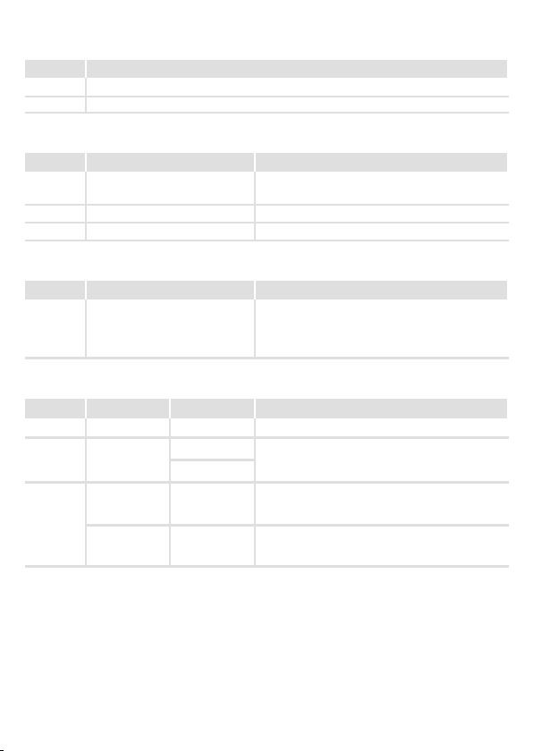
Displays
Pos. Colour Status Description
OK Yellow On Deviceis supplied with voltage.
Rx1
...
Rx8
L/C1
...
L/C8
Yellow
Green On Link
Red On Collision
On
Blinking
Activity
Connections A1 ... A8 send or receive data.
Connections A1 ... A8 are connected to the Ethernet
network.
Connection between connections A1 ... A8 and the
Ethernet network is inhibited due to collision.
14
EDK94AZCEH DE/EN/FR/ES/IT 1.0
Page 15

Mounting
Dimensions
a 114 mm
b 102 mm
c44mm
E94AZCEH001B
E94YCEH006
EDK94AZCEH DE/EN/FR/ES/IT 1.0
15
Page 16

Validity
These instructions are valid for
ƒ E94AZCEH hub (ETHERNET Powerlink) as of version 1A
Identification
c d
E94 A Z C EH 1A
Product series
Generation
Accessories
External accessories
ETHERNET Powerlink hub
Hardware version
Application range
The hub may be used for ETHERNET Powerlink networks
E94ZCEH002
16
EDK94AZCEH DE/EN/FR/ES/IT 1.0
Page 17

Contents i
1 Safety instructions 18.................................................
Definition of notes used 18.............................................
2 Electrical installation 19...............................................
Voltage supply 19.....................................................
Connection terminals 20..............................................
Ethernet connection 21...............................................
Cascading 22.........................................................
EDK94AZCEH DE/EN/FR/ES/IT 1.0
17
Page 18

1 Safety instructions
Definition of notes used
1 Safetyins tructions
Definition of notes used
The following pictographs and signal words are used in this documentation to indicate
dangers and important information:
Safety instructions
Structure of safety instructions:
Danger!
(characterises the type and severity of danger)
Note
(describes the danger and gives information about how to prevent dangerous
situations)
Pictograph and signal word Meaning
Danger of personal injury through dangerous electrical voltage.
Danger!
Danger!
Stop!
Application notes
Pictograph and signal word Meaning
Reference to an imminent danger that may r esult in death or
serious personal injury if the corresponding measures are not
taken.
Danger of personal injury through a general source of danger.
Reference to an imminent danger that may r esult in death or
serious personal injury if the corresponding measures are not
taken.
Danger of property damage.
Reference to a possible danger that may result in property
damage if the corresponding measures are not taken.
Note!
Tip!
18
Important note to ensure troublefree operation
Useful tip for simple handling
Reference to another documentation
EDK94AZCEH DE/EN/FR/ES/IT 1.0
Page 19

Electrical installation
2 Electricalinstallation
Voltage supply
External voltage supply
Stop!
Thedoubleplugconnectorterminalsare used to conduct the voltage supply.
The total current resulting from the series connection of several devices must
not exceed I
Plug connector connection:
Plug connector Explanation
+ Voltage supply
- Reference potential for voltage supply
=10Aperterminal.
max.
U = 24 V DC (20.4 V - 0 % ... 28.8 V + 0 %)
I = 210 mA
Voltage supply
2
E94AZCEH001C
EDK94AZCEH DE/EN/FR/ES/IT 1.0
19
Page 20

2 Electrical installation
Connection terminals
Connection terminals
Terminal data
Electrical connection Plug connector with spring connection
Possible connections
Bare end 10 mm
Useofpluggableterminalstrips
rigid: 2.5 mm2(AWG 12)
flexible:
without wire end ferrule
2.5 mm2(AWG 12)
with wire end ferrule, without plastic sleeve
2.5 mm2(AWG 12)
with wire end ferrule, with plastic sleeve
2.5 mm2(AWG 12)
Stop!
To avoid damage to pluggable terminal strips and contacts:
Wire pluggable terminal strips prior to connection!
Use of the pluggable terminal strip with spring connection
20
E94YCEH007B
EDK94AZCEH DE/EN/FR/ES/IT 1.0
Page 21

Electrical installation
Ethernet connection
Ethernet connection
Note!
Please use prefabricated standard cables (corresponding to ISO/IEC 11801 or
EN 50173) only:
ƒ cabletypeS/FTP
ƒ category CAT 5e
Pin assignment
2
E94ZCEH004
PIN
Pin assignment for port 1 (connection A1)
MDI (not crossed) MDIX (crossed)
1Tx+ Rx + Rx +
2 Tx - Rx - Rx -
3 Rx + Tx + Tx +
4 - - -
5 - - -
6 Rx - Tx - Tx -
7 - - -
8 - - -
EDK94AZCEH DE/EN/FR/ES/IT 1.0
Pin assignment for ports 2 - 8
(connections A2 ... A8)
21
Page 22

2 Electrical installation
Cascading
Cascading
Use the uplink port A1 to cascade the hubs:
E94AZCEH003
The hubs can be connected using a patch or a crossover cable.
Use the MDI / MDIX switch to select the uplink mode as shown in the following figure:
Patch cable Crossover cable
22
E94YCEH005
EDK94AZCEH DE/EN/FR/ES/IT 1.0
Page 23

Electrical installation
Cascading
2
EDK94AZCEH DE/EN/FR/ES/IT 1.0
23
Page 24
0Fig.0Tab. 0
Equipement livré
Pos. Description
- Répétiteur (Hub) ETHERNET Powerlink
- Instructions de montage
Raccordements
Pos. Raccordement Description
A1,
A2 ... A8
B Alimentation CC Bornier à lame ressort, 4 pôles
Ethernet Prise RJ45 selon la norme EN 50173
PE Filetage M3
Commutateur
Pos. Elément Explication
C Bouton-poussoir Active le croisement Rx/Tx pour le raccordement
A1 :
z ACTIVE : MDIX
z DESACTIVE : MDI
Affichages
Pos. Couleur Etat Description
OK jaune allumé L’appareil est sous tension.
Rx1
...
Rx8
L/C1
...
L/C8
jaune
vert allumé Lien
rouge allumé Collision
allumé
clignote
Activité
Des données sont envoyées ou reçues depuis les
raccords A1 ... A8.
La connexion des raccords A1 ... A8 au réseau
Ethernet est établie.
La connexion des raccords A1 ... A8 au réseau
Ethernet est bloquée en raison d’une collision.
24
EDK94AZCEH DE/EN/FR/ES/IT 1.0
Page 25

Montage
Encombrements
a 114 mm
b 102 mm
c44mm
E94AZCEH001B
E94YCEH006
EDK94AZCEH DE/EN/FR/ES/IT 1.0
25
Page 26

Validité
Le présent document s’applique aux :
ƒ Répétiteurs (Hub) E94AZCEH (ETHERNET Powerlink) à partir de la version 1A
Identification
E94ZCEH002
c d
E94 A Z C EH 1A
Série d’appareils
Génération d’appareils
Accessoires
Accessoires externes
Répétiteur (Hub) ET HERNET Powerlink
Version matérielle
Utilisation
L’utilisation du répétiteur (Hub) est autorisée pour la mise en réseau ETHERNET Powerlink
26
EDK94AZCEH DE/EN/FR/ES/IT 1.0
Page 27

Sommaire i
1 Consignes de sécurité 28...............................................
Définition des conventions utilisées 28...................................
2 Installation él ectrique 29...............................................
Alimentation 29......................................................
Spécifications des bornesde raccordement 30.............................
RaccordementEthernet 31.............................................
Mise en cascade 32....................................................
EDK94AZCEH DE/EN/FR/ES/IT 1.0
27
Page 28

1 Consignes de sécurité
Définition des conventions utilisées
1 Consignesde sécurité
Définition des conventions utilisées
Pour indiquer des risques et des informations importantes, la présente documentation
utilise les mots et symboles suivants :
Consignes de sécurité
Présentation des consignes de sécurité
Danger !
(Lepictogrammeindiqueletypederisque.)
Explication
(L’explication décrit le risque et les moyens de l’éviter.)
Pictogramme et mot associé Explication
Situation dangereuse pour les personnes en raison d’une tension
électrique élevée
Danger !
Danger !
Stop !
Consignes d’utilisation
Pictogramme et mot associé Explication
Indication d’un danger imminent qui peut avoir pour
conséquences des blessures mortelles ou très graves en cas de
non-respect des consignes de sécurité correspondantes
Situation dangereuse pour les personnes en raison d’un danger
d’ordre général
Indication d’un danger imminent qui peut avoir pour
conséquences des blessures mortelles ou très graves en cas de
non-respect des consignes de sécurité correspondantes
Risques de dégâts matériels
Indication d’un risque potentiel qui peut avoir pour
conséquences des dégâts matériels en cas de non-respect des
consignes de sécurité correspondantes
Remarque
importante !
Conseil !
28
Remarque importante pour assurer un fonctionnement correct
Conseil utile pour faciliter la mise en oeuvre
Référence à une autre documentation
EDK94AZCEH DE/EN/FR/ES/IT 1.0
Page 29

Installation électrique
2 Installation électrique
Alimentation
Alimentation externe
Stop !
L’installation de bornes doubles sur le bornier enfichable sert à la transmission
de l’alimentation. Le courant total provenant des contacts connectés en série
de plusieurs appareils ne doit pas dépasser la valeur de I
Raccordement bornier enfichable :
Bornier enfichable Explication
+ Alimentation
- Potentiel de référence pour l’alimentation
U = 24 V CC (20,4 V - 0 % ... 28,8 V + 0 %)
I = 210 mA
max.
Alimentation
2
E94AZCEH001C
=10Aparborne.
EDK94AZCEH DE/EN/FR/ES/IT 1.0
29
Page 30

2 Installation électrique
Spécifications des bornes de raccordement
Spécifications des bornes de raccordement
Spécifications des bornes de raccordement
Raccordement
électrique
Raccordements
possibles
Longueur du fil
dénudé
Manipulation des borniers enfichables
Connecteur avec raccordement par lames de ressorts
Rigide : 2,5 mm2(AWG 12)
Flexible :
sans embout
2,5 mm2(AWG 12)
avec embout, sans cosse en plastique
2,5 mm2(AWG 12)
avec embout et cosse en plastique
2,5 mm2(AWG 12)
10 mm
Stop !
Pour éviter d’endommager les borniers enfichables et les contacts :
commencer par câbler les borniers enfichables et les brancher ensuite !
Utilisation des borniers enfichables avec un raccordement par lames de ressorts
30
E94YCEH007B
EDK94AZCEH DE/EN/FR/ES/IT 1.0
Page 31

Installation électrique
Raccordement Ethernet
Raccordement Ethernet
Remarque importante !
Utiliser uniquement des câbles préfabriqués en vente dans le commerce
(conformes à la norme ISO/CEI 11801 ou EN 50173) :
ƒ Type de câble S/FTP
ƒ Catégorie CAT 5e
Affectation des broches
2
E94ZCEH004
BROCHE
Affectation des broches pour le port 1 (raccordement A1)
MDI (non croisé) MDIX (croisé)
1Tx+ Rx + Rx +
2 Tx - Rx - Rx -
3 Rx + Tx + Tx +
4 - - -
5 - - -
6 Rx - Tx - Tx -
7 - - -
8 - - -
EDK94AZCEH DE/EN/FR/ES/IT 1.0
Affectation des broches pour
les ports 2 à 8
(raccordements A2 ... A8)
31
Page 32

2 Installation électrique
Mise en cascade
Mise en cascade
Pour la mise en cascade du répétiteur, il faut utiliser le port de liaison montante A1 :
E94AZCEH003
Pour raccorder un répétiteur, vous pouvez utiliser un câble droit ou un câble croisé.
Paramétrez le mode Liaison montante (uplink) à l’aide du commutateur MDI / MDIX selon
l’illustration suivante :
Câble droit Câble croisé (cross-over)
32
E94YCEH005
EDK94AZCEH DE/EN/FR/ES/IT 1.0
Page 33

Installation électrique
Mise en cascade
2
EDK94AZCEH DE/EN/FR/ES/IT 1.0
33
Page 34

0Fig.0Tab. 0
Contenido del suministro
Pos. Descripción
- Hub ETHERNET Powerlink
- Instrucciones para el montaje
Conexiones
Pos. Conexión Descripción
A1,
A2 ... A8
B Alimentación de voltaje DC Regleta de conectores con conexión por fuerza de
Ethernet Conector RJ45 según EN 50173
resorte, 4 polos
PE Rosca M3
Interruptores
Pos. Elemento Explicación
C Botones Activa cruce Rx/Tx para la conexión A1:
z ON: MDIX
z OFF: MDI
Indicadores
Pos. Color Estado Descripción
OK amarillo encendido El equipo está siendo alimentado.
Rx1
...
Rx8
L/C1
...
L/C8
amarillo
verde encendido Link
rojo encendido Collision
encendido
parpadea
Activity
Se están enviado o recibiendo datos en las
conexiones A1 ... A8.
La conexión de las conexiones A1 ... A8 con la red
Ethernet está establecida.
La conexión de las conexiones A1 ... A8 con la red
Ethernet esta bloqueada por colisión.
34
EDK94AZCEH DE/EN/FR/ES/IT 1.0
Page 35

Montaje
Dimensiones
a 114 mm
b 102 mm
c44mm
E94AZCEH001B
E94YCEH006
EDK94AZCEH DE/EN/FR/ES/IT 1.0
35
Page 36

Validez
Este manual es de aplicación para
ƒ HubE94AZCEH (ETHERNET Powerlink) a partir de la versión 1A
Identificación
c d
E94 A Z C EH 1A
Serie de productos
Versión de equipos
Accesorios
Accesorios externos
Hub ETHERNET Powerlink
Versión de hardware
Posibilidades de uso
El uso del hub está permitido para la interconexión ETHERNET Powerlink
E94ZCEH002
36
EDK94AZCEH DE/EN/FR/ES/IT 1.0
Page 37

Contenido i
1 Instrucciones de seguridad 38...........................................
Definición de las instruccionesutilizadas 38...............................
2 Instalación eléctrica 39................................................
Alimentaciónde voltaje 39.............................................
Datos de l os bornes de conexión 40......................................
Conexión Ethernet 41.................................................
Cascada 42..........................................................
EDK94AZCEH DE/EN/FR/ES/IT 1.0
37
Page 38

1 Instrucciones de seguridad
Definiciónde las instrucciones utilizadas
1 Instr ucciones desegu ridad
Definición de las instrucciones utilizadas
Para indicar peligros e información importante, se utilizan en esta documentación los
siguientes términosindicativosy símbolos:
Instrucciones de seguridad
Estructura de las instrucciones de seguridad:
¡Peligro!
(indican el tipo y la gravedad del peligro)
Texto indicativo
(describe el peligro y da instrucciones para evitarlo)
Pictogramay término indicativo Significado
Riesgo de dañospersonales por voltajeeléctrico
¡Peligro!
¡Peligro!
¡Alto!
Instrucciones de uso
Pictogramay término indicativo Significado
Indica un pel igro inminente que puede causar la muerte o
lesiones graves si no se toman medidas adecuadas.
Riesgo de daños personales por una fuente de riesgo g eneral
Indica un pel igro inminente que puede causar la muerte o
lesiones graves si no se toman medidas adecuadas.
Peligro de dañosmateriales
Indicaunposible riesgo que puede ocasionardaños materiales si
no se toman las medidas adecuadas.
¡Aviso!
¡Sugerencia!
38
Nota importante para el funcionamiento sin fallos
Sugerenciaútil para facilitarla operación
Referenciaaotradocumentación
EDK94AZCEH DE/EN/FR/ES/IT 1.0
Page 39

Instalación eléctrica
Alimentación de voltaje
2 Instalacióne léctrica
Alimentación de voltaje
Alimentación de voltaje externa
¡Alto!
El equipamiento de la regleta de conectores con los bornes dobles sirve para la
conexión del voltaje de alimentación. La corriente total generada por la
conexión en serie de varios equipos no debe superar el valor de I
cada borne individual.
Conexión regleta de conectores:
Regleta de
conectores
+ Alimentación de voltaje
- Potencial de referencia para alimentación de voltaje
Explicación
U = 24 V DC (20,4 V - 0 % ... 28,8 V + 0 %)
I = 210 mA
máx.
2
E94AZCEH001C
=10Apor
EDK94AZCEH DE/EN/FR/ES/IT 1.0
39
Page 40

2 Instalación eléctrica
Datos de los bornes de conexión
Datos de los bornes de conexión
Datos de los bornes de conexión
Conexión eléctrica Regletade enchufes con conexión por muelle
Posibilidades de
conexión
Longitud de
aislamiento
Manipulación de regletas de bornes enchufables
10 mm
fija: 2,5 mm2(AWG 12)
flexible:
sin terminal grimpado
2,5 mm2(AWG 12)
con terminal grimpado, sin casquillo de plástico
2,5 mm2(AWG 12)
con terminal grimpado, con casquillo de plástico
2,5 mm2(AWG 12)
¡Alto!
Para no dañar regletas de bornes enchufables y contactos:
¡Primero cablear las regletas de bornes enchufables y luego enchufarlas!
Uso de la regleta de bornes enchufable con conexión de fuerza de resorte
40
E94YCEH007B
EDK94AZCEH DE/EN/FR/ES/IT 1.0
Page 41

Conexión Ethernet
¡Aviso!
Por favor, sólo utilice cables preconfeccionados comerciales (según
ISO/IEC 11801 o resp. EN 50173):
ƒ Tipo de cable S/FTP
ƒ Categoría CAT 5e
Asignación de pins
Instalación eléctrica
Conexión Ethernet
E94ZCEH004
2
PIN
Asignación de pins para el puerto 1 (conexión A1)
MDI (no cruzado) MDIX (cruzado)
1Tx+ Rx + Rx +
2 Tx - Rx - Rx -
3 Rx + Tx + Tx +
4 - - -
5 - - -
6 Rx - Tx - Tx -
7 - - -
8 - - -
EDK94AZCEH DE/EN/FR/ES/IT 1.0
Asingación de pins para el
puerto 2 - 8
(conexiones A2 ... A8)
41
Page 42

2 Instalación eléctrica
Cascada
Cascada
Para la cascada de hubs se ha de utilizar el puerto uplink A1:
LoshubspuedenserconectadosconuncablePatchouncableCrossover.
Configure el modo Uplink con el interruptor MDI / MDIX según el siguiente gráfico:
Cable Patch Cable Crossover (cable cruzado)
E94AZCEH003
42
E94YCEH005
EDK94AZCEH DE/EN/FR/ES/IT 1.0
Page 43

Instalación eléctrica
Cascada
2
EDK94AZCEH DE/EN/FR/ES/IT 1.0
43
Page 44

0Fig.0Tab. 0
Oggetto della fornitura
Pos. Descrizione
- Hub ETHERNET Powerlink
- Istruzioni di montaggio
Collegamenti
Pos. Collegamento Descrizione
A1,
A2 ... A8
B Alimentazione DC Morsettiera estraibile con collegamento a molla,
Ethernet Connettore RJ45 secondo EN 50173
4poli
PE Filettatura M3
Commutatore
Pos. Elemento Spiegazione
C Commutatore a pressione Attiva la commutazione Rx/Tx per il collegamento
A1:
z ON: MDIX
z OFF: MDI
Indicazioni luminose
Pos. Colore Stato Descrizione
OK giallo acceso Il dispositivo riceve tensione.
Rx1
...
Rx8
L/C1
...
L/C8
giallo
verde acceso Link
rosso acceso Collision
acceso
lampeggiante
Activity
È in corso l’invio o il ricevimento di dati dai
collegamenti A1 ... A8.
I collegamenti A1 ... A8 sono connessi alla rete
Ethernet.
La connessione dei collegamenti A1 ... A8 alla rete
Ethernet è inibita a causa di una collisione.
44
EDK94AZCEH DE/EN/FR/ES/IT 1.0
Page 45

Montaggio
Dimensioni
a 114 mm
b 102 mm
c44mm
E94AZCEH001B
E94YCEH006
EDK94AZCEH DE/EN/FR/ES/IT 1.0
45
Page 46

Validità
La presente documentazione è valida per
ƒ Hub E94AZCEH (ETHERNET Powerlink) a partire dalla versione 1A
Identificazione
c d
E94 A Z C EH 1A
Serie
Versione
Accessorio
Accessorio esterno
Hub ETHERNET Powerlink
Versione hardware
Compatibilità
L’utilizzo dell’hub è consentito per la rete ETHERNET Powerlink
E94ZCEH002
46
EDK94AZCEH DE/EN/FR/ES/IT 1.0
Page 47

Sommario i
1 Informazioni sulla sicurezza 48..........................................
Simbologiadelle note e avvertenze utilizzate 48...........................
2 Installazione elettrica 49...............................................
Alimentazione 49.....................................................
Morsettiera di collegamento 50.........................................
Collegamento Ethernet 51.............................................
Collegamentoin cascata 52............................................
EDK94AZCEH DE/EN/FR/ES/IT 1.0
47
Page 48

1 Informazioni sulla sicurezza
Simbologia delle note e avvertenze utilizzate
1 Informazioni sullasicurezza
Simbologia delle note e avvertenze utilizzate
Per segnalare pericoli ed informazioni importanti, nella presente documentazione sono
riportati i seguenti simboli e parole di segnalazione:
Note di sicurezza
Struttura delle note di sicurezza:
Pericolo!
(indica il tipo e la gravità del pericolo)
Testo della nota
(descrive il pericolo e fornisce indicazioni su come può essere evitato)
Simbolo e parola di segnalazione Significato
Pericolo di danni alle persone dovuti a tensione elettrica
Pericolo!
Pericolo!
Stop!
Note di utilizzo
Simbolo e parola di segnalazione Significato
Avvertenza:
Segnala una situazione di pericolo che può provocare morte o
gravi lesioni se non vengono osservate le necessarie misure
precauzionali.
Pericolo di danni alle persone dovuti a una fonte generica di
pericolo
Segnala una situazione di pericolo che può provocare morte o
gravi lesioni se non vengono osservate le necessarie misure
precauzionali.
Pericolo di danni materiali
Segnala un possibile pericolo che può provocare danni materiali
se non vengono osservate le necessarie misure precauzionali.
Avvertenza importante per assicurare un corretto
funzionamento dell’apparecchiatura
Suggerimento:
48
Utile suggerimento per una più semplice gestione
Rimando ad altra documentazione
EDK94AZCEH DE/EN/FR/ES/IT 1.0
Page 49

Installazione elettrica
2 Installazioneelettrica
Alimentazione
Alimentazione esterna
Stop!
La morsettiera con doppi morsetti in dotazione serve per il collegamento
dell’alimentazione. La corrente totale risultante dal collegamento in serie di
più dispositivi non può superare il valore di I
Collegamento morsettiera:
Morsettiera
estraibile
+ Alimentazione
- Potenziale di riferimento per alimentazione
Spiegazione
U = 24 V DC (20,4 V - 0 % ... 28,8 V + 0 %)
I = 210 mA
=10Apersingolomorsetto.
max.
Alimentazione
2
E94AZCEH001C
EDK94AZCEH DE/EN/FR/ES/IT 1.0
49
Page 50

2 Installazione elettrica
Morsettiera di collegamento
Morsettiera di collegamento
Dati dei morsetti di collegamento
Collegamento
elettrico
Possibilità di
collegamento
Lunghezza di
spellatura
Precauzioni con morsettiere estraibili
Serie di prese a spina con collegamento a molla
rigido: 2,5 mm2(AWG 12)
flessibile:
senza capocorda
2,5 mm2(AWG 12)
con capocorda, senza bussola di plastica
2,5 mm2(AWG 12)
con capocorda, con bussola di plastica
2,5 mm2(AWG 12)
10 mm
Stop!
Pernondanneggiarelemorsettiereestraibilieicontatti:
Eseguire il cablaggio delle morsettiere prima di inserirle nel dispositivo.
Uso della morsettiera estraibile con collegamento a molla
50
E94YCEH007B
EDK94AZCEH DE/EN/FR/ES/IT 1.0
Page 51

Installazione elettrica
Collegamento Ethernet
Collegamento Ethernet
Avvertenza:
Utilizzare solo cavi preconfezionati standard (secondo ISO/IEC 11801 o EN
50173):
ƒ Tipo di cavo S/FTP
ƒ Categoria CAT 5e
Assegnazione dei pin
2
E94ZCEH004
PIN
Assegnazione pin per Porta 1 (collegamento A1)
MDI (non incrociato) MDIX (incrociato)
1Tx+ Rx + Rx +
2 Tx - Rx - Rx -
3 Rx + Tx + Tx +
4 - - -
5 - - -
6 Rx - Tx - Tx -
7 - - -
8 - - -
EDK94AZCEH DE/EN/FR/ES/IT 1.0
Assegnazione pin per Porta 2 8
(collegamenti A2 ... A8)
51
Page 52

2 Installazione elettrica
Collegamento in cascata
Collegamento in cascata
Per il collegamento in cascata degli hub è necessario utilizzare la porta Uplink A1:
E94AZCEH003
Gli hub possono essere connessi con un cavo di tipo patch o crossover.
Impostare con il commutatore MDI / MDIX il modo Uplink, come mostrato nella figura
seguente:
Cavo patch Cavo crossover (cavo incrociato)
52
E94YCEH005
EDK94AZCEH DE/EN/FR/ES/IT 1.0
Page 53

Installazione elettrica
Collegamento in cascata
2
EDK94AZCEH DE/EN/FR/ES/IT 1.0
53
Page 54

Lenze Drive Systems GmbH
Hans-Lenze-Straße 1
D-31855 Aerzen
Germany
Service
¬ Service
E-Mail Lenze@Lenze.de
Internet www.Lenze.com
+49 (0) 51 54 82-0
00 80 00 24 4 68 77 (24 h helpline)
+49 (0) 51 54 82-1112
EDK94AZCEH
DE/EN/FR/ES/IT 1.0
© 04/2007
TD06
10987654321
 Loading...