

Page 1
EDK94AZCDM
.L[D
L−force Drives
Montageanleitung
Mounting Instructions
Instructions de montage
Ä.L[Dä
Instrucciones para el montaje
Istruzioni per il montaggio
9400 30 ... 100 A
+A1
-K2
J
12 3
E94AZCDM030, E94AZCDM100
+K1
-A2
5
4
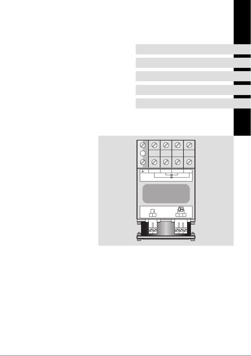
Diodenmodul
Diode module
Module de diode
Módulo de diodos
Modulo diodi
Page 2

Lesen Sie zuerst diese Anleitung und die Dokumentation zum
Grundgerät, bevor Sie mit den Arbeiten beginnen!
Beachten Sie die enthaltenen Sicherheitshinweise.
Please read these instructions and the documentation of the standard
device before you start working!
Observe the safety instructions given therein!
Lire le présent fascicule et la documentation relative à l’appareil de base
avant toute manipulation de l’équipement !
Respecter les consignes de sécurité fournies.
Lea estas instrucciones y la documentación del equipo básico antes de
empezar a trabajar.
Observe las instrucciones de seguridad indicadas.
Prima di iniziare qualsiasi intervento, leggere le presenti istruzioni e la
documentazione relativa al dispositivo di base.
Osservare le note di sicurezza.
Page 3

Inhalt i
1 Über diese Dokumentation 4. . . . . . . . . . . . . . . . . . . . . . . . . . . . . . . . . . . . . . . . .
1.1 Informationen zur Gültigkeit 4. . . . . . . . . . . . . . . . . . . . . . . . . . . . . . . . .
1.2 Zielgruppe 4. . . . . . . . . . . . . . . . . . . . . . . . . . . . . . . . . . . . . . . . . . . . . . . .
1.3 Dokumenthistorie 5. . . . . . . . . . . . . . . . . . . . . . . . . . . . . . . . . . . . . . . . . .
1.4 Verwendete Konventionen 5. . . . . . . . . . . . . . . . . . . . . . . . . . . . . . . . . . .
1.5 Verwendete Hinweise 6. . . . . . . . . . . . . . . . . . . . . . . . . . . . . . . . . . . . . . .
2 Sicherheitshinweise 8. . . . . . . . . . . . . . . . . . . . . . . . . . . . . . . . . . . . . . . . . . . . . . .
2.1 Allgemeine Sicherheitshinweise 8. . . . . . . . . . . . . . . . . . . . . . . . . . . . . .
2.2 Restgefahren 9. . . . . . . . . . . . . . . . . . . . . . . . . . . . . . . . . . . . . . . . . . . . . .
3 Produktbeschreibung 10. . . . . . . . . . . . . . . . . . . . . . . . . . . . . . . . . . . . . . . . . . . . .
3.1 Lieferumfang 10. . . . . . . . . . . . . . . . . . . . . . . . . . . . . . . . . . . . . . . . . . . . . .
3.2 Identifikation 10. . . . . . . . . . . . . . . . . . . . . . . . . . . . . . . . . . . . . . . . . . . . . .
3.3 Einsatzbedingungen 10. . . . . . . . . . . . . . . . . . . . . . . . . . . . . . . . . . . . . . . .
3.4 Anschlussdaten 11. . . . . . . . . . . . . . . . . . . . . . . . . . . . . . . . . . . . . . . . . . . .
3.4.1 Daten der Anschlussklemmen 12. . . . . . . . . . . . . . . . . . . . . . .
4 Technische Daten 13. . . . . . . . . . . . . . . . . . . . . . . . . . . . . . . . . . . . . . . . . . . . . . . . .
4.1 Allgemeine Daten und Einsatzbedingungen 13. . . . . . . . . . . . . . . . . . . .
5 Elektrische Installation 16. . . . . . . . . . . . . . . . . . . . . . . . . . . . . . . . . . . . . . . . . . . . .
5.1 Mindestverdrahung 16. . . . . . . . . . . . . . . . . . . . . . . . . . . . . . . . . . . . . . . .
EDK94AZCDM DE/EN/FR/ES/IT 1.0
3
Page 4

1
Über diese Dokumentation
Informationen zur Gültigkeit
1 Über diese Dokumentation
0Abb. 0Tab. 0
1.1 Informationen zur Gültigkeit
Diese Anleitung ist gültig für
ƒ Diodenmodul E94AZCDM030
ƒ Diodenmodul E94AZCDM100
1.2 Zielgruppe
Diese Dokumentation richtet sich an qualifiziertes Fachpersonal nach
IEC 60364.
Qualifiziertes Fachpersonal sind Personen, die für die auszuführenden Tätigkeiten bei der Aufstellung, Montage, Inbetriebsetzung und dem Betrieb des Produkts über entsprechende Qualifikationen verfügen.
Tipp!
Informationen und Hilfsmittel rund um die Lenze−Produkte finden
Sie im Download−Bereich unter
http://www.Lenze.com
4
EDK94AZCDM DE/EN/FR/ES/IT 1.0
Page 5
1.3 Dokumenthistorie
Materialnummer Version Beschreibung
.L[D 1.0 06/2013 TD06 Neuerstellung
1.4 Verwendete Konventionen
Informationsart Auszeichnung Beispiele/Hinweise
Zahlenschreibweise
Dezimaltrennzeichen
Warnhinweise
UR−Warnhinweise
Symbole
Seitenverweis Verweis auf eine andere Seite mit
Dokumentationsverweis Verweis auf eine andere Dokumen-
Über diese Dokumentation
Dokumenthistorie
Punkt Es wird generell der Dezimalpunkt
verwendet.
Zum Beispiel: 1234.56
Werden nur in der englischen Sprache verwendet.
zusätzlichen Informationen
Zum Beispiel: 16 = siehe Seite 16
tation mit zusätzlichen Informationen
Zum Beispiel: EDKxxx = siehe
Dokumentation EDKxxx
1
EDK94AZCDM DE/EN/FR/ES/IT 1.0
5
Page 6

1
Über diese Dokumentation
Verwendete Hinweise
1.5 Verwendete Hinweise
Um auf Gefahren und wichtige Informationen hinzuweisen, werden in dieser
Dokumentation folgende Piktogramme und Signalwörter verwendet:
Sicherheitshinweise
Aufbau der Sicherheitshinweise:
Gefahr!
(kennzeichnet die Art und die Schwere der Gefahr)
Hinweistext
(beschreibt die Gefahr und gibt Hinweise, wie sie vermieden werden
kann)
Piktogramm und Signalwort Bedeutung
Gefahr!
Gefahr!
Stop!
Anwendungshinweise
Gefahr von Personenschäden durch gefährliche elektrische Spannung
Hinweis auf eine unmittelbar drohende Gefahr, die den
Tod oder schwere Verletzungen zur Folge haben kann,
wenn nicht die entsprechenden Maßnahmen getroffen
werden.
Gefahr von Personenschäden durch eine allgemeine
Gefahrenquelle
Hinweis auf eine unmittelbar drohende Gefahr, die den
Tod oder schwere Verletzungen zur Folge haben kann,
wenn nicht die entsprechenden Maßnahmen getroffen
werden.
Gefahr von Sachschäden
Hinweis auf eine mögliche Gefahr, die Sachschäden zur
Folge haben kann, wenn nicht die entsprechenden Maßnahmen getroffen werden.
Piktogramm und Signalwort Bedeutung
Hinweis!
Tipp!
6
Wichtiger Hinweis für die störungsfreie Funktion
Nützlicher Tipp für die einfache Handhabung
Verweis auf andere Dokumentation
EDK94AZCDM DE/EN/FR/ES/IT 1.0
Page 7

Über diese Dokumentation
Verwendete Hinweise
Spezielle Sicherheitshinweise und Anwendungshinweise für UR
Piktogramm und Signalwort Bedeutung
Sicherheitshinweis oder Anwendungshinweis für den
Betrieb eines UR−approbierten Geräts in UL−approbier-
Warnings!
ten Anlagen.
Möglicherweise wird das Antriebssystem nicht UL−gerecht betrieben, wenn nicht die entsprechenden Maßnahmen getroffen werden.
1
EDK94AZCDM DE/EN/FR/ES/IT 1.0
7
Page 8

2
Sicherheitshinweise
Allgemeine Sicherheitshinweise
2 Sicherheitshinweise
2.1 Allgemeine Sicherheitshinweise
Gefahr!
Wenn Sie die folgenden grundlegenden Sicherheitsmaßnahmen
missachten, kann dies zu schweren Personenschäden und
Sachschäden führen:
ƒ Lenze−Antriebs− und Automatisierungskomponenten ...
... ausschließlich bestimmungsgemäß verwenden.
... niemals trotz erkennbarer Schäden in Betrieb nehmen.
... niemals technisch verändern.
... niemals unvollständig montiert in Betrieb nehmen.
... niemals ohne erforderliche Abdeckungen betreiben.
... können während und nach dem Betrieb − ihrer Schutzart entsprechend −
spannungsführende, auch bewegliche oder rotierende Teile haben. Oberflächen können heiß sein.
ƒ Alle Vorgaben der beiliegenden und zugehörigen Dokumentation
beachten.
Dies ist Voraussetzung für einen sicheren und störungsfreien Betrieb sowie
für das Erreichen der angegebenen Produkteigenschaften.
Die in diesem Dokument dargestellten verfahrenstechnischen Hinweise
und Schaltungsausschnitte sind Vorschläge, deren Übertragbarkeit auf die
jeweilige Anwendung überprüft werden muss. Für die Eignung der angegebenen Verfahren und Schaltungsvorschläge übernimmt der Hersteller keine
Gewähr.
ƒ Alle Arbeiten mit und an Lenze−Antriebs− und
Automatisierungskomponenten darf nur qualifiziertes Fachpersonal
ausführen.
Nach IEC 60364 bzw. CENELEC HD 384 sind dies Personen, ...
... die mit Aufstellung, Montage, Inbetriebsetzung und Betrieb des Produkts
vertraut sind.
... die über die entsprechenden Qualifikationen für ihre Tätigkeit verfügen.
... die alle am Einsatzort geltenden Unfallverhütungsvorschriften, Richtli-
nien und Gesetze kennen und anwenden können.
8
EDK94AZCDM DE/EN/FR/ES/IT 1.0
Page 9

2.2 Restgefahren
Gefahr!
Gefährliche elektrische Spannung
Alle Leistungsanschlüsse führen bis zu 3 Minuten nach
Netz−Ausschalten gefährliche elektrische Spannung.
Mögliche Folgen:
ƒ Tod oder schwere Verletzungen beim Berühren der
Leistungsanschlüsse.
Schutzmaßnahmen:
ƒ Vor Arbeiten an den Leistungsanschlüssen Netz abschalten und
mindestens 3 Minuten warten.
ƒ Prüfen, ob alle Leistungsanschlüsse spannungsfrei sind.
Warnings!
Conditions of Acceptability:
When used in the end−product equipment the following are among
the considerations to be made.
ƒ These devices are intended to be used only with Lenze AC motor
controllers, Series Cat. No. E94ASxE, E94AMxE, E94APxE or
E94ARxP followed by three digits numbers, which are UL Listed in
File E132659, evaluated to 500 Vac.
ƒ This device is suitable for use in a surrounding air temperature of
45 °C or 55 °C, as specified in the Electrical Ratings.
Sicherheitshinweise
Restgefahren
2
EDK94AZCDM DE/EN/FR/ES/IT 1.0
9
Page 10
3
Produktbeschreibung
Lieferumfang
3 Produktbeschreibung
3.1 Lieferumfang
ƒ 1 Stück Diodenmodul E94AZCDMxxx:
– E94AZCDM030
– E94AZCDM100
ƒ 1 Stück Montageanleitung
3.2 Identifikation
Typenschlüssel E94 A Z C DM xxx
Produktreihe
Gerätegeneration
Zubehör
Externes Zubehör
Typ Diodenmodul
Dauerstrom
l 030: 30 A
l 100: 100 A
3.3 Einsatzbedingungen
Die Verwendung dieses Diodenmoduls ist zulässig mit Geräten der Produktreihe 9400 ab der Typenschildbezeichnung
ƒ E94ASxE
ƒ E94AMxE
ƒ E94APxE
ƒ E94ARxP
10
EDK94AZCDM DE/EN/FR/ES/IT 1.0
Page 11
3.4 Anschlussdaten
+K1
-K2
+A1
-A2
E94AZCDMxxx
J
12
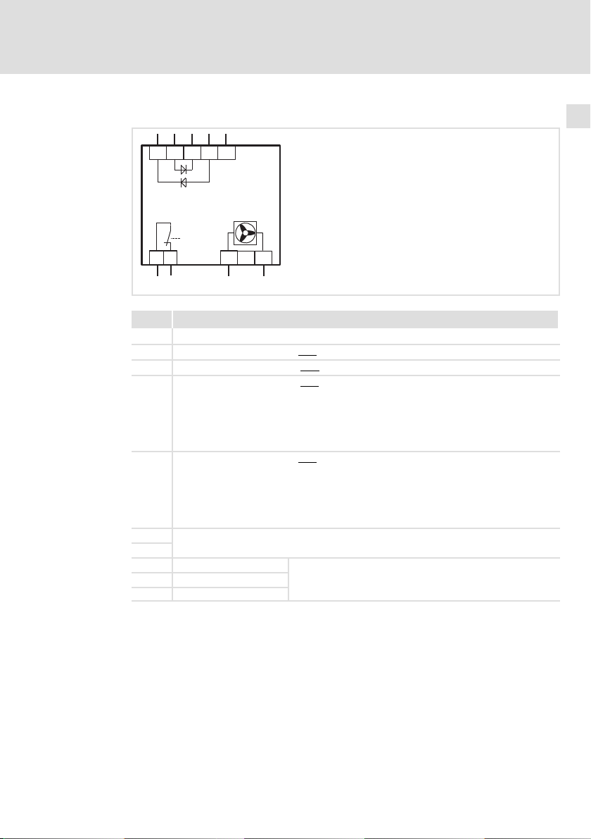
Pos. Beschreibung
PE−Anschluss
−K2 Zwischenkreisspannung −UG vom Servo Umrichter 9400 (E94ASxE0864 ... E94ASxE6954)
+A1 Zwischenkreisspannung +UG vom Servo Umrichter 9400 (E94ASxE0864 ... E94ASxE6954)
+K1 Zwischenkreisspannung +UG zum
Servo Umrichter 9400:
l E94ASxE0024 ... E94ASxE0594
l E94AMxE0024 ... E94AMxE0594
l E94APxE0024 ... E94APxE0594
l E94ARxE0024 ... E94ARxE0594
−A2 Zwischenkreisspannung −UG zum
Servo Umrichter 9400:
l E94ASxE0024 ... E94ASxE0594
l E94AMxE0024 ... E94AMxE0594
l E94APxE0024 ... E94APxE0594
l E94ARxE0024 ... E94ARxE0594
1
Thermoschalter (öffnet bei 90 °C)
2
3 24 V − Lüfteranschluss
5 GND
4 Nicht belegt
+
Produktbeschreibung
3
Anschlussdaten
5
3
4
E94AZCDM002
Nur verfügbar bei Diodenmodul E94AZCDM100
EDK94AZCDM DE/EN/FR/ES/IT 1.0
11
Page 12

3
Produktbeschreibung
Anschlussdaten
Daten der Anschlussklemmen
3.4.1 Daten der Anschlussklemmen
PE −K2 / +A1 / +K1 /
Anschlussader starr 0.75 ... 50 mm
Anschlussader flexibel mit Aderendhülse
mit Kunstoffkragen
Abisolierlänge 16 mm 16 mm 7 mm 7 mm
Anzugsmoment 3.2 ... 3.7 Nm
(AWG 18 ... 0/1)
0.75 ... 35 mm
(AWG 24 ... 2)
(28.3 ... 32.7
lb−in)
−A2
2
0.75 ... 50 mm
(AWG 18 ... 0/1)
2
0.75 ... 35 mm
(AWG 24 ... 2)
3.2 ... 3.7 Nm
(28.3 ... 32.7
lb−in)
1 / 2 3 / 5
2
0.2 ... 2.5 mm
(AWG 24 ... 12)
2
0.2 ... 2.5 mm
(AWG 24 ... 12)
0.5 ... 0.6 Nm
(4.4 ... 5.3 lb−in)
2
0.2 ... 2.5 mm
(AWG 24 ... 12)
2
0.2 ... 2.5 mm
(AWG 24 ... 12)
0.5 ... 0.6 Nm
(4.4 ... 5.3 lb−in)
2
2
12
EDK94AZCDM DE/EN/FR/ES/IT 1.0
Page 13
Allgemeine Daten und Einsatzbedingungen
4 Technische Daten
4.1 Allgemeine Daten und Einsatzbedingungen
Konformität und Approbationen
Konformität
l CE 2006/95/EG Niederspannungsrichtlinie
Approbation
l UR UL508C: Industrial Control Equipment
Personenschutz und Geräteschutz
Schutzart EN 60529 IP 20
Isolationsfestigkeit EN 61800−5−1
Isolation von Steuerschaltkreisen EN 61800−5−1
EMV
Störfestigkeit
(nach Anforderungen EN 61800−3)
l elektrostatische Entladung
(ESD)
l Hochfrequenz
– leitungsgeführt EN 61000−4−6 150 kHz ... 80 MHz, 10 V/m
– Einstrahlung (Gehäuse) EN 61000−4−3 80 MHz ... 1000 MHz, 10 V/m
l Burst
– Leistungsanschlüsse und Lei-
stungsschnittstellen
– Signalschnittstellen EN 61000−4−4 1 kV/5 kHz
– Steueranschlüsse EN 61000−4−4 2 kV/5 kHz
l Surge (Stoßspannung)
– Leistungsanschlüsse EN 61000−4−5 1.2/50 s,
Störaussendung, leitungsgeführt Es sind die Angaben des Gerätehandbuchs der Gerätereihe
2004/108/EG EMV−Richtlinie
Lenze File No. 132659
l < 2000 m ü. NN: Überspannungskategorie III
l > 2000 m ü. NN: Überspannungskategorie II
Sichere Trennung vom Netz durch doppelte/verstärkte Isolierung
Die Gerätete sind für die Anwendung in einer Industrieumgebung vorgesehen. Beim Einsatz an öffentlichen Netzen
sind Maßnahmen zu treffen, um die zu erwartende Aussendung von Funkstörungen zu begrenzen.
EN 61000−4−2 8 kV bei Luftentladung,
EN 61000−4−4 2 kV/5 kHz
Servo Drive 9400 (EDS94SPP101) zu beachten.
C2 nach EN 61800−3
Technische Daten
4 kV bei Kontaktentladung
gegen Gehäuse
80 % AM (1kHz)
80 % AM (1kHz)
1 kV Phase−Phase, 2 kV Phase−PE
4
EDK94AZCDM DE/EN/FR/ES/IT 1.0
13
Page 14
4
Technische Daten
Allgemeine Daten und Einsatzbedingungen
Umgebungsbedingungen E94AZCDM030 E94AZCDM100
Klimatisch
Zulässige Umgebungstemperatur
Maximale Kühlkörpertemperatur 90 °C 90 °C
Lagerung l IEC/EN 60721−3−1
Transport l IEC/EN 60721−3−2
Betrieb l IEC/EN 60721−3−3
Verschmutzung EN 61800−5−1/UL840 Verschmutzungsgrad 2
Aufstellhöhe l 0 ... 4000 müNN
Elektrisch
Nennstrom 2 x 30 A 2 x 100 A
Nennspannung 705 VDC 705 VDC
Spitzenstrom
*) Alle folgende Stromangaben in Klammern beziehen sich auf E94AZCDM100:
3 Minuten Zykluszeit: Max. 60 s bei 38 A (150 A), danach 120 s Erholzeit mit max. 24 A (90 A)
5 s Zykluszeit: Max. 0.5 s bei 60 A (225 A), danach 4.5 s Erhohlzeit mit max. 24 A (90 A)
Sperrspannung 1600 V 1600 V
Lüfter − U = 24 VDC +/− 10 %
Temperaturüberwachung Thermoschalter öffnet bei 90 °C
Mechanisch
Vibrationsfestigkeit
*)
Transport
45 °C 45 °C
– 1K3 (−25 ... +60 °C) < 6 Monate
– 1K3 (−25 ... +40 °C) > 6 Monate
– 2K3 (−25 ... +70 °C)
– 3K3 (−10 ... +55 °C)
– Bei Betrieb über +40 °C: Ausgangsbemessungsstrom
um 2.5 %/°C reduzieren
l 1000 ... 4000 müNN: Ausgangsbemessungsstrom um 5
%/1000m reduzieren
38 A (60 s)
60 A (0.5 s)
l EN 60721−3−2
– 2M2
– 2 ... 9 Hz: Amplitude 3.5mm
– 10 ... 200 Hz: beschleunigungsfest bis 10 m/s
– 200 ... 500 Hz: beschleunigungsfest bis 15 m/s
Betrieb l EN 61800−5−1
– 10 ... 57 Hz: Amplitude 0.075mm
– 57 ... 150 Hz: beschleunigungsfest bis 10 m/s
l Germanischer Lloyd allgemeine Schwingungsbeanspru-
chungen, Kennlinie 1
– 5 ... 13.2 Hz: Amplitude ±1mm
– 13.2 ... 100 Hz: beschleunigungsfest bis 0.7 g
150 A (60 s)
225 A (0.5 s)
I = 0.4 A
2
2
2
14
EDK94AZCDM DE/EN/FR/ES/IT 1.0
Page 15

Technische Daten
Allgemeine Daten und Einsatzbedingungen
Montagebedingungen E94AZCDM030 E94AZCDM100
Einbauort Im Schaltschrank
Einbaulage Vertikal
Einbaufreiräume
Befestigungsart Hutschienenmontage
Elektrische Anschlüsse Schraubanschlüsse
Abmessungen (B × H × T) 85 × 180 × 150 mm 85 × 195 × 150 mm
Masse 2.1 kg 2.3 kg
oberhalb:
unterhalb:
seitlich:
80 mm
120 mm
ohne Abstand anreihbar
4
EDK94AZCDM DE/EN/FR/ES/IT 1.0
15
Page 16
5
Elektrische Installation
Mindestverdrahung
5 Elektrische Installation
5.1 Mindestverdrahung
L1
L2
L3
N
PE
K1
F1
F2...F4
O
I
R
J
B
K1
Z1
L1 L2
F8
F9
L3
-UG
+UG
+
X100
+K1
-K2
-A2
+A1
+
E94AZCDMxxx
J
12
3
E94AZCDM100
24 V
F10
5
4
GND
E94ASxE0864
...
E94ASxE6954
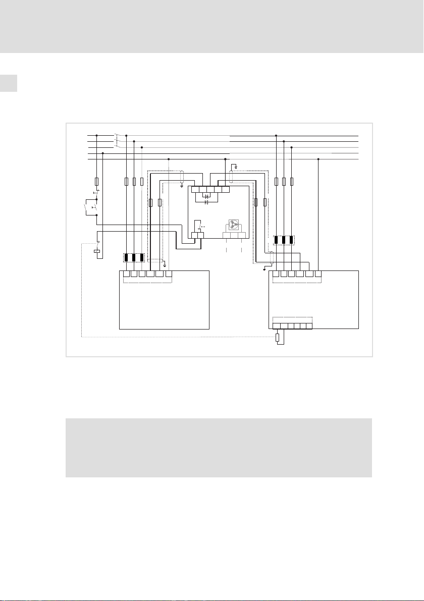
Abb. 5−1 9400−Leistungsverbund mit Diodenmodul E94AZCDMxxx
K1 Netzschütz
F1 ... F7 Sicherung
F8 ... F11 DC−Sicherung
Z1, Z2 Netzdrossel
F11
Z2
L1 L2
Rb1 Rb2
R
B
F5...F7
L3
-UG
+UG
+
X100
E94ASxE0024
...
E94ASxE0594
X105
U
VW
+
SSP94NF002
16
Hinweis!
Bei Brems−, oder Rückspeisebetrieb ist das Brems−, oder
Rückspeisemodul stets zusammen mit der Gruppe der kleinerenˆ
Servoregler mit anzuschließen.
Durch Einsatz des Diodenmoduls wird der Einschaltstrom nur von den Geräten
der Bauform 7 und größer in Richtung der Geräte BF6 und kleiner zugelassen.
Diesem Strom stellen sich die Einschaltstrombegrenzungen beider Geräte entgegen. Überschlägig kann somit davon ausgegangen werden, dass jedes Gerät
seinen eigenen Zwischenkreiskondensator lädt.
EDK94AZCDM DE/EN/FR/ES/IT 1.0
Page 17

Contents i
1 About this documentation 18. . . . . . . . . . . . . . . . . . . . . . . . . . . . . . . . . . . . . . . . . .
1.1 Validity information 18. . . . . . . . . . . . . . . . . . . . . . . . . . . . . . . . . . . . . . . .
1.2 Target group 18. . . . . . . . . . . . . . . . . . . . . . . . . . . . . . . . . . . . . . . . . . . . . .
1.3 Document history 18. . . . . . . . . . . . . . . . . . . . . . . . . . . . . . . . . . . . . . . . . .
1.4 Conventions used 19. . . . . . . . . . . . . . . . . . . . . . . . . . . . . . . . . . . . . . . . . . .
1.5 Notes used 20. . . . . . . . . . . . . . . . . . . . . . . . . . . . . . . . . . . . . . . . . . . . . . . .
2 Safety instructions 22. . . . . . . . . . . . . . . . . . . . . . . . . . . . . . . . . . . . . . . . . . . . . . . .
2.1 General safety information 22. . . . . . . . . . . . . . . . . . . . . . . . . . . . . . . . . . .
2.2 Residual hazards 23. . . . . . . . . . . . . . . . . . . . . . . . . . . . . . . . . . . . . . . . . . .
3 Product description 24. . . . . . . . . . . . . . . . . . . . . . . . . . . . . . . . . . . . . . . . . . . . . . .
3.1 Scope of supply 24. . . . . . . . . . . . . . . . . . . . . . . . . . . . . . . . . . . . . . . . . . . .
3.2 Identification 24. . . . . . . . . . . . . . . . . . . . . . . . . . . . . . . . . . . . . . . . . . . . . .
3.3 Operating conditions 24. . . . . . . . . . . . . . . . . . . . . . . . . . . . . . . . . . . . . . . .
3.4 Connection data 25. . . . . . . . . . . . . . . . . . . . . . . . . . . . . . . . . . . . . . . . . . . .
3.4.1 Terminal data 26. . . . . . . . . . . . . . . . . . . . . . . . . . . . . . . . . . . .
4 Technical data 27. . . . . . . . . . . . . . . . . . . . . . . . . . . . . . . . . . . . . . . . . . . . . . . . . . . .
4.1 General data and operating conditions 27. . . . . . . . . . . . . . . . . . . . . . . .
5 Electrical installation 30. . . . . . . . . . . . . . . . . . . . . . . . . . . . . . . . . . . . . . . . . . . . . .
5.1 Minimum wiring 30. . . . . . . . . . . . . . . . . . . . . . . . . . . . . . . . . . . . . . . . . .
EDK94AZCDM DE/EN/FR/ES/IT 1.0
17
Page 18

1
About this documentation
Validity information
1 About this documentation
0Fig. 0Tab. 0
1.1 Validity information
These instructions are valid for
ƒ E94AZCDM030 diode module
ƒ E94AZCDM100 diode module
1.2 Target group
This documentation is directed at qualified skilled personnel according to
IEC 60364.
Qualified skilled personnel are persons who have the required qualifications to
carry out all activities involved in installing, mounting, commissioning, and
operating the product.
Tip!
Information and auxiliary devices related to the Lenze products can
1.3 Document history
be found in the download area at
http://www.Lenze.com
Material number Version Description
.L[D 1.0 06/2013 TD06 New edition
18
EDK94AZCDM DE/EN/FR/ES/IT 1.0
Page 19
1.4 Conventions used
Type of information Identification Examples/notes
Spelling of numbers
Decimal separator
Warning
UR warning
Icons
Page reference Reference to another page with
Documentation reference Reference to another documentation
About this documentation
Conventions used
Point In general, the decimal point is used.
For instance: 1234.56
Are only used in English language.
additional information
For instance: 16 = see page 16
with additional information
For example: EDKxxx = see
documentation EDKxxx
1
EDK94AZCDM DE/EN/FR/ES/IT 1.0
19
Page 20
1
About this documentation
Notes used
1.5 Notes used
The following pictographs and signal words are used in this documentation to
indicate dangers and important information:
Safety instructions
Structure of safety instructions:
Danger!
Pictograph and signal word Meaning
Danger!
Danger!
Stop!
Application notes
(characterises the type and severity of danger)
Note
(describes the danger and gives information about how to prevent
dangerous situations)
Danger of personal injury through dangerous electrical
voltage.
Reference to an imminent danger that may result in
death or serious personal injury if the corresponding
measures are not taken.
Danger of personal injury through a general source of
danger.
Reference to an imminent danger that may result in
death or serious personal injury if the corresponding
measures are not taken.
Danger of property damage.
Reference to a possible danger that may result in
property damage if the corresponding measures are not
taken.
20
Pictograph and signal word Meaning
Note!
Tip!
Important note to ensure troublefree operation
Useful tip for simple handling
Reference to another documentation
EDK94AZCDM DE/EN/FR/ES/IT 1.0
Page 21

About this documentation
Special safety instructions and application notes for UR
Pictograph and signal word Meaning
Safety note or application note for the operation of a
Warnings!
UR−approved unit in UL−approved systems.
The drive system may not be operated in accordance
with UL if the corresponding measures are not taken.
1
Notes used
EDK94AZCDM DE/EN/FR/ES/IT 1.0
21
Page 22

2
Safety instructions
General safety information
2 Safety instructions
2.1 General safety information
Danger!
Disregarding the following basic safety measures may lead to
severe personal injury and damage to material assets!
ƒ Lenze drive and automation components ...
... must only be used for the intended purpose.
... must never be operated if damaged.
... must never be subjected to technical modifications.
... must never be operated unless completely assembled.
... must never be operated without the covers/guards.
... can − depending on their degree of protection − have live, movable or
rotating parts during or after operation. Surfaces can be hot.
ƒ All specifications of the corresponding enclosed documentation must be
observed.
This is vital for a safe and trouble−free operation and for achieving the
specified product features.
The procedural notes and circuit details provided in this document are
proposals which the user must check for suitability for his application. The
manufacturer does not accept any liability for the suitability of the specified
procedures and circuit proposals.
ƒ Only qualified skilled personnel are permitted to work with or on Lenze
drive and automation components.
According to IEC 60364 or CENELEC HD 384, these are persons ...
... who are familiar with the installation, assembly, commissioning and
operation of the product,
... possess the appropriate qualifications for their work,
... and are acquainted with and can apply all the accident prevent
regulations, directives and laws applicable at the place of use.
22
EDK94AZCDM DE/EN/FR/ES/IT 1.0
Page 23

2.2 Residual hazards
Danger!
Dangerous electrical voltage
All power terminals remain live for up to three minutes after mains
disconnection.
Possible consequences:
ƒ Death or severe injuries when touching the power terminals.
Protective measures:
ƒ Switch off the power supply and wait for at least three minutes
before working on the power terminals.
ƒ Make sure that all power terminals are deenergised.
Warnings!
Conditions of Acceptability:
When used in the end−product equipment the following are among
the considerations to be made.
ƒ These devices are intended to be used only with Lenze AC motor
controllers, Series Cat. No. E94ASxE, E94AMxE, E94APxE or
E94ARxP
followed by three digits numbers, which are UL Listed in File
E132659, evaluated to 500 Vac.
ƒ This device is suitable for use in a surrounding air temperature of
45 °C or 55 °C, as specified in the Electrical Ratings.
Safety instructions
Residual hazards
2
EDK94AZCDM DE/EN/FR/ES/IT 1.0
23
Page 24

3
Product description
Scope of supply
3 Product description
3.1 Scope of supply
ƒ 1 x E94AZCDMxxx diode module :
– E94AZCDM030
– E94AZCDM100
ƒ 1 x mounting instructions
3.2 Identification
Type code E94 a Z C DM xxx
Product range
Version
accessories
External accessories
Diode module type
Continuous current
l 030: 30 A
l 100: 100 A
3.3 Operating conditions
This diode module may be used in conjunction with devices of the 9400 product
series as of nameplate designation
ƒ E94ASxE
ƒ E94AMxE
ƒ E94APxE
ƒ E94ARxP
24
EDK94AZCDM DE/EN/FR/ES/IT 1.0
Page 25

3.4 Connection data
+K1
-K2
+A1
-A2
E94AZCDMxxx
J
12
Pos. Description
PE connection
−K2 DC−bus voltage −UG from servo inverter 9400 (E94ASxE0864 ... E94ASxE6954)
+A1 DC−bus voltage +UG from servo inverter 9400 (E94ASxE0864 ... E94ASxE6954)
+K1 DC−bus voltage +UG to
servo inverter 9400:
l E94ASxE0024 ... E94ASxE0594
l E94AMxE0024 ... E94AMxE0594
l E94APxE0024 ... E94APxE0594
l E94ARxE0024 ... E94ARxE0594
−A2 DC−bus voltage −UG to
servo inverter 9400:
l E94ASxE0024 ... E94ASxE0594
l E94AMxE0024 ... E94AMxE0594
l E94APxE0024 ... E94APxE0594
l E94ARxE0024 ... E94ARxE0594
1
Thermal switch (opens at 90 °C)
2
3 24 V fan connection
5 GND
4 not assigned
+
Product description
3
Connection data
5
3
4
E94AZCDM002
Only available with E94AZCDM100 diode module
EDK94AZCDM DE/EN/FR/ES/IT 1.0
25
Page 26

3
Product description
Connection data
Terminal data
3.4.1 Terminal data
PE −K2 / +A1 / +K1 /
Rigid terminal 0.75 ... 50 mm
Flexible terminal
with wire end ferrule
with plastic collar
Stripping length 16 mm 16 mm 7 mm 7 mm
Tightening torque 3.2 ... 3.7 Nm
(AWG 18 ... 0/1)
0.75 ... 35 mm
(AWG 24 ... 2)
(28.3 ... 32.7
lb−in)
−A2
2
0.75 ... 50 mm
(AWG 18 ... 0/1)
2
0.75 ... 35 mm
(AWG 24 ... 2)
3.2 ... 3.7 Nm
(28.3 ... 32.7
lb−in)
1 / 2 3 / 5
2
0.2 ... 2.5 mm
(AWG 24 ... 12)
2
0.2 ... 2.5 mm
(AWG 24 ... 12)
0.5 ... 0.6 Nm
(4.4 ... 5.3 lb−in)
2
0.2 ... 2.5 mm
(AWG 24 ... 12)
2
0.2 ... 2.5 mm
(AWG 24 ... 12)
0.5 ... 0.6 Nm
(4.4 ... 5.3 lb−in)
2
2
26
EDK94AZCDM DE/EN/FR/ES/IT 1.0
Page 27

General data and operating conditions
4 Technical data
4.1 General data and operating conditions
Conformity and approvals
Conformity
l CE 2006/95/EG Low−Voltage Directive
2004/108/EG EMC Directive
Approval
l UR UL508C: Industrial Control Equipment
Lenze File No. 132659
Protection of persons and devices
Type of protection EN 60529 IP 20
Insulation resistance EN 61800−5−1
l < 2000 m amsl: Overvoltage category III
l > 2000 m amsl: Overvoltage category II
Insulation of control circuits EN 61800−5−1
Safe mains isolation through double/reinforced insulation
Technical data
4
EMC
Noise immunity
(according to requirements EN
61800−3)
l Electrostatic discharge (ESD) EN 61000−4−2 8 kV for air discharge,
l Radio frequency
– cable−guided EN 61000−4−6 150 kHz ... 80 MHz, 10 V/m
– Interference (housing) EN 61000−4−3 80 MHz ... 1000 MHz, 10 V/m
l Burst
– Power connections and
interfaces
– Signal interfaces EN 61000−4−4 1 kV/5 kHz
– Control connections EN 61000−4−4 2 kV/5 kHz
l Surge (surge voltage)
– Power terminals EN 61000−4−5 1.2/50 s,
Noise emission, cable−guided Observe the information of the hardware manual of the
EDK94AZCDM DE/EN/FR/ES/IT 1.0
The controllers are designed for use in an industrial
environment. Operation on public networks requires
measures to be taken for limiting the expected emission of
radio interferences.
4 kV for contact discharge to
housing
80% AM (1kHz)
80% AM (1kHz)
EN 61000−4−4 2 kV/5 kHz
1 kV phase/phase,
2 kV phase/PE
Servo Drive 9400 (EDS94SPP101) version.
C2 acc. to EN 61800−3
27
Page 28

4
Technical data
General data and operating conditions
Ambient conditions E94AZCDM030 E94AZCDM100
Climatic
Permissible ambient temperature
Maximum heatsink temperature 90 °C 90 °C
Storage l IEC/EN 60721−3−1
Transport l IEC/EN 60721−3−2
Operation l IEC/EN 60721−3−3
Pollution EN 61800−5−1/UL840 degree of pollution 2
Site altitude l 0 ... 4000 m amsl
Electrical
Rated current 2 x 30 A 2 x 100 A
Rated voltage 705 VDC 705 VDC
Peak current
*) The following current data in brackets refer to E94AZCDM100:
3 minutes cycle time: Max. 60 s at 38 A (150 A), afterwards 120 s recovery time with max. 24 A (90 A)
5 s cycle time: Max. 0.5 s at 60 A (225 A), afterwards 4.5 s recovery time with max. 24 A (90 A)
Reverse voltage 1600 V 1600 V
Fan − V = 24 VDC +/− 10 %
Temperature monitoring Thermal switch opens at 90 °C
Mechanical
Vibration resistance
*)
Transport
Operation l EN 61800−5−1
45 °C 45 °C
– 1K3 (−25 ... +60 °C) < 6 months
– 1K3 (−25 ... +40 °C) > 6 months
– 2K3 (−25 ... +70 °C)
– 3K3 (−10 ... +55 °C)
– In case of operations above +40 °C: Reduce the rated
output current by 2.5 %/°C
l 1000 ... 4000 m amsl: Reduce rated output current by 5
%/1000m
38 A (60 s)
60 A (0.5 s)
l EN 60721−3−2
– 2M2
– 2 ... 9 Hz: Amplitude 3.5mm
– 10 ... 200 Hz: acceleration resistant up to 10 m/s
– 200 ... 500 Hz: acceleration resistant up to 15 m/s
– 10 ... 57 Hz: Amplitude 0.075mm
– 57 ... 150 Hz: Acceleration resistant up to 10 m/s
l Germanischer Lloyd, general vibration stress,
characteristic 1
– 5 ... 13.2 Hz: Amplitude ±1mm
– 13.2 ... 100 Hz: acceleration resistant up to 0.7 g
150 A (60 s)
225 A (0.5 s)
I = 0.4 A
2
2
2
28
EDK94AZCDM DE/EN/FR/ES/IT 1.0
Page 29

Technical data
General data and operating conditions
Mounting conditions E94AZCDM030 E94AZCDM100
Mounting place In the control cabinet
Mounting position Vertical
Free spaces
Mounting type DIN rail mounting
Electrical connections Screw connections
Dimensions (B ×H × T) 85 × 180 × 150 mm 85 × 195 × 150 mm
Mass 2.1 kg 2.3 kg
Above:
Below:
To the sides:
80 mm
120 mm
Side−by−side mounting without any clearance
4
EDK94AZCDM DE/EN/FR/ES/IT 1.0
29
Page 30

5
Electrical installation
Minimum wiring
5 Electrical installation
5.1 Minimum wiring
L1
L2
L3
N
PE
K1
F1
F2...F4
O
I
R
J
B
K1
Z1
L1 L2
F8
F9
L3
-UG
+UG
+
X100
+K1
-K2
-A2
+A1
+
E94AZCDMxxx
J
12
3
E94AZCDM100
24 V
F10
5
4
GND
E94ASxE0864
...
E94ASxE6954
Fig. 5−1 9400 power system with E94AZCDMxxx diode module
K1 Mains contactor
F1 ... F7 Fuse
F8 ... F11 DC fuse
Z1, Z2 Mains choke
F11
Z2
L1 L2
Rb1 Rb2
R
B
F5...F7
L3
-UG
+UG
+
X100
E94ASxE0024
...
E94ASxE0594
X105
U
VW
+
SSP94NF002
30
Note!
In case of braking operation or regenerative feedback, the brake
module or regenerative module must always be connected to the
group with the smallerˆ servo controllers.
When a diode module is used, the starting current is only admitted by devices
of type 7 and bigger towards the devices BF6 and smaller.
The starting current limitations of both devices oppose this current. Thus, it can
be assumed that each device charges its own DC−bus capacitor.
EDK94AZCDM DE/EN/FR/ES/IT 1.0
Page 31

Sommaire i
1 Présentation du document 32. . . . . . . . . . . . . . . . . . . . . . . . . . . . . . . . . . . . . . . . .
1.1 Validité 32. . . . . . . . . . . . . . . . . . . . . . . . . . . . . . . . . . . . . . . . . . . . . . . . . . .
1.2 Public visé 32. . . . . . . . . . . . . . . . . . . . . . . . . . . . . . . . . . . . . . . . . . . . . . . . .
1.3 Historique du document 32. . . . . . . . . . . . . . . . . . . . . . . . . . . . . . . . . . . . .
1.4 Conventions utilisées 33. . . . . . . . . . . . . . . . . . . . . . . . . . . . . . . . . . . . . . .
1.5 Consignes utilisées 34. . . . . . . . . . . . . . . . . . . . . . . . . . . . . . . . . . . . . . . . .
2 Consignes de sécurité 36. . . . . . . . . . . . . . . . . . . . . . . . . . . . . . . . . . . . . . . . . . . . . .
2.1 Consignes générales de sécurité 36. . . . . . . . . . . . . . . . . . . . . . . . . . . . . . .
2.2 Dangers résiduels 37. . . . . . . . . . . . . . . . . . . . . . . . . . . . . . . . . . . . . . . . . .
3 Description du produit 38. . . . . . . . . . . . . . . . . . . . . . . . . . . . . . . . . . . . . . . . . . . . .
3.1 Equipement livré 38. . . . . . . . . . . . . . . . . . . . . . . . . . . . . . . . . . . . . . . . . . .
3.2 Identification 38. . . . . . . . . . . . . . . . . . . . . . . . . . . . . . . . . . . . . . . . . . . . . .
3.3 Conditions d’utilisation 38. . . . . . . . . . . . . . . . . . . . . . . . . . . . . . . . . . . . . .
3.4 Données de raccordement 39. . . . . . . . . . . . . . . . . . . . . . . . . . . . . . . . . . .
3.4.1 Données des bornes de raccordement 40. . . . . . . . . . . . . . . . .
4 Spécifications techniques 41. . . . . . . . . . . . . . . . . . . . . . . . . . . . . . . . . . . . . . . . . .
4.1 Caractéristiques générales et conditions d’utilisation 41. . . . . . . . . . . .
5 Installation électrique 44. . . . . . . . . . . . . . . . . . . . . . . . . . . . . . . . . . . . . . . . . . . . .
5.1 Câblage minimal 44. . . . . . . . . . . . . . . . . . . . . . . . . . . . . . . . . . . . . . . . . .
EDK94AZCDM DE/EN/FR/ES/IT 1.0
31
Page 32

1
Présentation du document
Validité
1 Présentation du document
0Fig. 0Tab. 0
1.1 Validité
Le présent document s’applique au produits suivants :
ƒ Module de diode E94AZCDM030
ƒ Module de diode E94AZCDM100
1.2 Public visé
Cette documentation s’adresse à un personnel qualifié et habilité
conformément à la norme CEI 60364.
On entend par "personnel qualifié et habilité" des personnes compétentes en
matière d’installation, de montage, de mise en service et de fonctionnement du
produit et possédant les qualifications correspondant à leurs activités.
Conseil !
Toutes les informations relatives aux produits Lenze peuvent être
1.3 Historique du document
téléchargées sur notre site à l’adresse suivante :
http://www.Lenze.com
Numéro de document Version Description
.L[D 1.0 06/2013 TD06 Nouvelle édition
32
EDK94AZCDM DE/EN/FR/ES/IT 1.0
Page 33

1.4 Conventions utilisées
Type d’information Aperçu Exemples/remarques
Représentation des chiffres
Séparateur décimal
Consignes préventives
Consignes préventives UR
Pictogrammes
Renvoi à la page Renvoi à une autre page contenant
Renvoi à une documentation Renvoi à une autre documentation
Présentation du document
Conventions utilisées
Point Le point décimal est généralement
utilisé.
Exemple : 1234.56
Uniquement en anglais
des informations supplémentaires.
Par exemple : 16 = voir page 16
contenant des informations
supplémentaires.
Par exemple : EDKxxx = voir la
documentation EDKxxx
1
EDK94AZCDM DE/EN/FR/ES/IT 1.0
33
Page 34

1
Présentation du document
Consignes utilisées
1.5 Consignes utilisées
Pour indiquer des risques et des informations importantes, la présente
documentation utilise les mots et pictogrammes suivants :
Consignes de sécurité
Présentation des consignes de sécurité
Danger !
(Le pictogramme indique le type de risque.)
Explication
(L’explication décrit le risque et les moyens de l’éviter.)
Pictogramme et mot associé Explication
Danger !
Danger !
Stop !
Consignes d’utilisation
Situation dangereuse pour les personnes en raison
d’une tension électrique élevée
Indication d’un danger imminent qui peut avoir pour
conséquences des blessures mortelles ou très graves en
cas de non−respect des consignes de sécurité
correspondantes
Situation dangereuse pour les personnes en raison d’un
danger d’ordre général
Indication d’un danger imminent qui peut avoir pour
conséquences des blessures mortelles ou très graves en
cas de non−respect des consignes de sécurité
correspondantes
Risques de dégâts matériels
Indication d’un risque potentiel qui peut avoir pour
conséquences des dégâts matériels en cas de
non−respect des consignes de sécurité correspondantes
34
Pictogramme et mot associé Explication
Remarque
importante !
Conseil !
Remarque importante pour assurer un fonctionnement
correct
Conseil utile pour faciliter la mise en uvre
Renvoi à une autre documentation
EDK94AZCDM DE/EN/FR/ES/IT 1.0
Page 35

Présentation du document
Consignes utilisées
Consignes de sécurité et d’utilisation spécifiques selon UR
Pictogramme et mot associé Description
Consigne de sécurité ou d’utilisation pour le
fonctionnement d’un appareil homologué UR dans des
Warnings!
installations homologuées UL.
Le système d’entraînement risque de ne pas être utilisé
selon les directives UL si des mesures correspondantes
ne sont pas prévues.
1
EDK94AZCDM DE/EN/FR/ES/IT 1.0
35
Page 36

2
Consignes de sécurité
Consignes générales de sécurité
2 Consignes de sécurité
2.1 Consignes générales de sécurité
Danger !
Le non−respect des consignes fondamentales de sécurité suivantes
peut entraîner des blessures et des dommages matériels graves.
ƒ Les composants d’entraînement et d’automatisation Lenze ...
... doivent exclusivement être utilisés conformément à leur fonction.
... ne doivent jamais être mis en service si des dommages sont décelés.
... ne doivent jamais être modifiés d’un point de vue technique.
... ne doivent jamais être mis en service s’ils ne sont pas montés
intégralement.
... ne doivent jamais être mis en service sans le capot obligatoire.
... peuvent − selon l’indice de protection − contenir des pièces sous tension, en
mouvement ou en rotation. Les surfaces peuvent être brûlantes.
ƒ Respecter les consignes et les indications contenues dans la
documentation concernée.
Il s’agit de la condition préalable pour garantir un fonctionnement sûr et
fiable et pour obtenir les caractéristiques du produit indiquées.
Les procédures à suivre et les plans de raccordement fournis constituent des
recommandations dont l’adéquation avec l’application concernée doit être
vérifiée. Lenze n’assumera aucune responsabilité pour les dommages liés à
un problème d’adéquation des procédures et plans de raccordements
indiqués.
ƒ Les travaux réalisés avec et au niveau des composants d’entraînement et
d’automatisation Lenze ne doivent être exécutés que par un personnel
qualifié et habilité.
Selon les normes CEI 60364 ou CENELEC HD 384, ces personnes doivent ...
... connaître parfaitement l’installation, le montage, la mise en service et le
fonctionnement du produit.
... posséder les qualifications appropriées pour l’exercice de leur activité.
... connaître toutes les prescriptions pour la prévention d’accidents,
directives et lois applicables sur le lieu d’utilisation et être en mesure de les
appliquer.
36
EDK94AZCDM DE/EN/FR/ES/IT 1.0
Page 37

2.2 Dangers résiduels
Danger !
Tension électrique dangereuse
Les raccordements de puissance sont encore sous tension jusqu’à 3
minutes après la coupure réseau.
Risques encourus
ƒ Mort ou blessures graves en cas de contact accidentel avec les
raccordements de puissance.
Mesures de protection
ƒ Avant toute intervention au niveau des raccordements de
puissance, couper l’alimentation et attendre au moins 3 minutes.
ƒ S’assurer que tous les raccordements de puissance sont hors
tension.
Consignes de sécurité
Dangers résiduels
2
Warnings!
Conditions of Acceptability:
When used in the end−product equipment the following are among
the considerations to be made.
ƒ These devices are intended to be used only with Lenze AC motor
controllers, Series Cat. No. E94ASxE, E94AMxE, E94APxE or
E94ARxP
followed by three digits numbers, which are UL Listed in File
E132659, evaluated to 500 Vac.
ƒ This device is suitable for use in a surrounding air temperature of
45 °C or 55 °C, as specified in the Electrical Ratings.
EDK94AZCDM DE/EN/FR/ES/IT 1.0
37
Page 38

3
Description du produit
Equipement livré
3 Description du produit
3.1 Equipement livré
ƒ 1 module de diode E94AZCDMxxx:
– E94AZCDM030
– E94AZCDM100
ƒ 1 documentation "Instructions de montage"
3.2 Identification
Codification des types E94 A Z C DM xxx
Série d’appareils
Génération d’appareils
Accessoire
Accessoire externe
Type module de diode
Courant permanent
l 030 : 30 A
l 100 : 100 A
3.3 Conditions d’utilisation
L’utilisation de ce module de diode est autorisée pour les appareils de la série
9400 à partir de la version suivante (voir plaque signalétique) :
ƒ E94ASxE
ƒ E94AMxE
ƒ E94APxE
ƒ E94ARxP
38
EDK94AZCDM DE/EN/FR/ES/IT 1.0
Page 39

3.4 Données de raccordement
+K1
-K2
+A1
-A2
+
E94AZCDMxxx
J
12
Pos. Description
Raccordement PE
−K2 Tension du bus CC −UG depuis le servovariateur 9400 (E94ASxE0864 ... E94ASxE6954)
+A1 Tension du bus CC +UG depuis le servovariateur 9400 (E94ASxE0864 ... E94ASxE6954)
+K1 Tension du bus CC +UG vers le
servovariateur 9400 :
l E94ASxE0024 ... E94ASxE0594
l E94AMxE0024 ... E94AMxE0594
l E94APxE0024 ... E94APxE0594
l E94ARxE0024 ... E94ARxE0594
−A2 Tension du bus CC −UG vers le
servovariateur 9400 :
l E94ASxE0024 ... E94ASxE0594
l E94AMxE0024 ... E94AMxE0594
l E94APxE0024 ... E94APxE0594
l E94ARxE0024 ... E94ARxE0594
1
Contact thermique (ouverture à 90 °C)
2
3 Raccordement
ventilateur 24 V
5 GND
4 Non affecté
5
3
4
Description du produit
Données de raccordement
Uniquement pour module de diode E94AZCDM100
3
E94AZCDM002
EDK94AZCDM DE/EN/FR/ES/IT 1.0
39
Page 40

3
Description du produit
Données de raccordement
Données des bornes de raccordement
3.4.1 Données des bornes de raccordement
PE −K2 / +A1 / +K1 /
Fil de raccordement
rigide
Fil de raccordement
flexible avec embout
avec collerette en
plastique
Longueur de fil
dénudé
Couple de serrage 3.2 ... 3.7 Nm
0.75 ... 50 mm
(AWG 18 ... 0/1)
0.75 ... 35 mm
(AWG 24 ... 2)
16 mm 16 mm 7 mm 7 mm
(28.3 ... 32.7
lb−in)
−A2
2
0.75 ... 50 mm
(AWG 18 ... 0/1)
2
0.75 ... 35 mm
(AWG 24 ... 2)
3.2 ... 3.7 Nm
(28.3 ... 32.7
lb−in)
1 / 2 3 / 5
2
0.2 ... 2.5 mm
(AWG 24 ... 12)
2
0.2 ... 2.5 mm
(AWG 24 ... 12)
0.5 ... 0.6 Nm
(4.4 ... 5.3 lb−in)
2
0.2 ... 2.5 mm
(AWG 24 ... 12)
2
0.2 ... 2.5 mm
(AWG 24 ... 12)
0.5 ... 0.6 Nm
(4.4 ... 5.3 lb−in)
2
2
40
EDK94AZCDM DE/EN/FR/ES/IT 1.0
Page 41

Spécifications techniques
Caractéristiques générales et conditions d’utilisation
4 Spécifications techniques
4.1 Caractéristiques générales et conditions d’utilisation
Norme appliquée et homologation
Norme appliquée
l CE 2006/95/CE Directive Basse Tension
Homologation
l UR UL508C: Industrial Control Equipment
Protection des personnes et protection des appareils
Indice de protection EN 60529 IP20
Résistance d’isolement EN 61800−5−1
Isolation des circuits de
commande
2004/108/CE Directive CEM
Lenze File No. 132659
l Altitude d’implantation < 2000 m : catégorie de surtension III
l >Altitude d’implantation > 2000 m : catégorie de surtension II
EN 61800−5−1
Séparation fiable du réseau par isolement double (renforcé)
4
CEM
Protection contre les parasites
(respect des exigences de la
norme EN 61800−3)
l Décharges électrostatiques EN 61000−4−2 8 kV pour espace d’isolement,
l Haute fréquence
– Haute fréquence
conduite par câble
– Rayonnement haute
fréquence (boîtier)
l Transitoires rapides en
salves
– Raccordements de
puissance et interfaces
– Interfaces de signaux EN 61000−4−4 1 kV/5 kHz
– Raccordements de
commande
l Ondes de choc (tension de
choc)
– Raccordements de
puissance
EDK94AZCDM DE/EN/FR/ES/IT 1.0
Les appareils sont prévus pour être utilisés dans un
environnement industriel. Pour une utilisation sur réseau public,
prévoir des mesures supplémentaires permettant de réduire
l’émission probable des interférences radio.
4 kV pour contact de décharge
EN 61000−4−6 150 kHz ... 80 MHz, 10 V/m
EN 61000−4−3 80 MHz ... 1000 MHz, 10 V/m
EN 61000−4−4 2 kV/5 kHz
EN 61000−4−4 2 kV/5 kHz
EN 61000−4−5 1.2/50 s,
80 % AM (1 kHz)
80 % AM (1 kHz)
1 kV phase−phase,
2 kV phase−PE
41
Page 42

4
Spécifications techniques
Caractéristiques générales et conditions d’utilisation
CEM
Perturbations
radioélectriques, émission
conduite par câble
Conditions ambiantes E94AZCDM030 E94AZCDM100
Conditions climatiques
Température ambiante admise
Température radiateur
maximale
Stockage l CEI/EN 60721−3−1
Transport l CEI/EN 60721−3−2
Fonctionnement l CEI/EN 60721−3−3
Pollution ambiante admissible EN 61800−5−1/UL840 degré de pollution 2
Altitude d’implantation l 0 ... 4000 m au−dessus du niveau de la mer
Conditions électriques
Courant nominal 2 x 30 A 2 x 100 A
Tension nominale 705 V CC 705 V CC
Courant de pointe
*) Les valeurs de courants entre parenthèses se rapportent à l’appareil E94AZCDM100 :
Cycle de 3 minutes : 60 s max. à 38 A (150 A), suivi d’un temps de repos de 120 s à 24 A max. (90 A)
Cycle de 5 minutes : 0.5 s max. à 60 A (225 A), suivi d’un temps de repos de 4.5 s à 24 A max. (90 A)
Tension de blocage 1600 V 1600 V
Ventilateur − U = 24 V CC +/− 10 %
Surveillance de la température Ouverture du contact thermique à 90 °C
Conditions mécaniques
Résistance aux vibrations
*)
Transport
Tenir compte des indications fournies dans le manuel des
appareils Servo Drive 9400 (EDS94SPP101).
C2 selon EN 61800−3
45 °C 45 °C
90 °C 90 °C
– 1K3 (−25 ... +60 °C) < 6 mois
– 1K3 (−25 ... +40 °C) > 6 mois
– 2K3 (−25 ... +70 °C)
– 3K3 (−10 ... +55 °C)
– > +40 °C : réduire le courant assigné de sortie de 2.5 %/°C.
l 1000 ... 4000 m au−dessus du niveau de la mer : réduire le
courant assigné de sortie de 5 %/ 1000 m.
38 A (60 s)
60 A (0.5 s)
l EN 60721−3−2
– 2M2
– 2 ... 9 Hz : amplitude de 3.5 mm
– 10 ... 200 Hz : résistance à l’accélération jusqu’à 10 m/s
– 200 ... 500 Hz : résistance à l’accélération jusqu’à 15 m/s
150 A (60 s)
225 A (0.5 s)
I = 0.4 A
2
2
42
EDK94AZCDM DE/EN/FR/ES/IT 1.0
Page 43

Spécifications techniques
Caractéristiques générales et conditions d’utilisation
E94AZCDM100E94AZCDM030Conditions ambiantes
Fonctionnement l EN 61800−5−1
Conditions de montage E94AZCDM030 E94AZCDM100
Emplacement de montage À l’intérieur de l’armoire électrique
Position de montage Montage vertical
Espaces de montage
Au−dessus de l’appareil :
En dessous de l’appareil :
Sur le côté de l’appareil :
Mode de fixation Montage sur rails profilés
Raccordements électriques Fixation par vis
Encombrements (L ×H × P) 85 × 180 × 150 mm 85 × 195 × 150 mm
Poids 2.1 kg 2.3 kg
– 10 ... 57 Hz : amplitude de 0.075 mm
– 57 ... 150 Hz : résistance à l’accélération jusqu’à 10 m/s
l Germanischer Lloyd, contraintes de vibrations, courbe
caractéristique 1
– 5 ... 13.2 Hz : amplitude de ± 1 mm
– 13.2 ... 100 Hz : résistance à l’accélération jusqu’à 0.7 g
80 mm
120 mm
Juxtaposition possible sans espacement
4
2
EDK94AZCDM DE/EN/FR/ES/IT 1.0
43
Page 44

5
Installation électrique
Câblage minimal
5 Installation électrique
5.1 Câblage minimal
L1
L2
L3
N
PE
K1
F1
F2...F4
O
I
R
J
B
K1
Z1
L1 L2
F8
F9
L3
-UG
+UG
+
X100
+K1
-K2
-A2
+A1
+
E94AZCDMxxx
J
12
3
E94AZCDM100
24 V
F10
F11
5
4
Z2
GND
L1 L2
E94ASxE0864
...
E94ASxE6954
Rb1 Rb2
R
B
Fig.5−1 Réseau de puissance 9400 avec module de diode E94AZCDMxxx
K1 Contacteur réseau
F1 ... F7 Fusible
F8 ... F11 Fusible CC
Z1, Z2 Self réseau
F5...F7
L3
-UG
+UG
+
X100
E94ASxE0024
...
E94ASxE0594
X105
U
VW
+
SSP94NF002
44
Remarque importante !
En fonctionnement en freinage ou en générateur, le module de
freinage ou le module de renvoi sur le réseau doit toujours être
raccordé avec le groupe des servovariateurs ayant la puissance la
plus faibleˆ.
L’utilisation d’un module de diode permet de n’autoriser le courant de charge
que depuis les appareils de taille 7 ou plus gros, vers les modules de taille 6 ou
plus petits. Les fonctions de limitations de courant de démarrage des deux
appareils agissent à l’encontre de ce courant. Il est donc considéré que chaque
appareil charge son propre condensateur du bus CC.
EDK94AZCDM DE/EN/FR/ES/IT 1.0
Page 45

Contenido i
1 Acerca de esta documentación 46. . . . . . . . . . . . . . . . . . . . . . . . . . . . . . . . . . . . . .
1.1 Información sobre la validez 46. . . . . . . . . . . . . . . . . . . . . . . . . . . . . . . . . .
1.2 Grupo objetivo 46. . . . . . . . . . . . . . . . . . . . . . . . . . . . . . . . . . . . . . . . . . . . .
1.3 Historia del documento 46. . . . . . . . . . . . . . . . . . . . . . . . . . . . . . . . . . . . . .
1.4 Convenciones utilizadas 47. . . . . . . . . . . . . . . . . . . . . . . . . . . . . . . . . . . . .
1.5 Indicaciones utilizadas 48. . . . . . . . . . . . . . . . . . . . . . . . . . . . . . . . . . . . . .
2 Instrucciones de seguridad 49. . . . . . . . . . . . . . . . . . . . . . . . . . . . . . . . . . . . . . . . .
2.1 Instrucciones generales de seguridad 49. . . . . . . . . . . . . . . . . . . . . . . . . .
2.2 Peligros residuales 50. . . . . . . . . . . . . . . . . . . . . . . . . . . . . . . . . . . . . . . . . .
3 Descripción del producto 51. . . . . . . . . . . . . . . . . . . . . . . . . . . . . . . . . . . . . . . . . .
3.1 Alcance del suministro 51. . . . . . . . . . . . . . . . . . . . . . . . . . . . . . . . . . . . . .
3.2 Identificación 51. . . . . . . . . . . . . . . . . . . . . . . . . . . . . . . . . . . . . . . . . . . . . .
3.3 Condiciones de uso 51. . . . . . . . . . . . . . . . . . . . . . . . . . . . . . . . . . . . . . . . .
3.4 Datos de conexión 52. . . . . . . . . . . . . . . . . . . . . . . . . . . . . . . . . . . . . . . . . .
3.4.1 Datos de los bornes de conexión 53. . . . . . . . . . . . . . . . . . . . .
4 Datos técnicos 54. . . . . . . . . . . . . . . . . . . . . . . . . . . . . . . . . . . . . . . . . . . . . . . . . . . .
4.1 Datos generales y condiciones de uso 54. . . . . . . . . . . . . . . . . . . . . . . . .
5 Instalación eléctrica 58. . . . . . . . . . . . . . . . . . . . . . . . . . . . . . . . . . . . . . . . . . . . . . .
5.1 Cableado mínimo 58. . . . . . . . . . . . . . . . . . . . . . . . . . . . . . . . . . . . . . . . .
EDK94AZCDM DE/EN/FR/ES/IT 1.0
45
Page 46

1
Acerca de esta documentación
Información sobre la validez
1 Acerca de esta documentación
0Fig. 0Tab. 0
1.1 Información sobre la validez
Este manual es de aplicación para
ƒ Módulo de diodos E94AZCDM030
ƒ Módulo de diodos E94AZCDM100
1.2 Grupo objetivo
Esta documentación va dirigida a personal experto y cualificado según
IEC 60364.
Personal experto cualificado son aquellas personas que disponen de las
cualificaciones adecuadas para realizar los trabajos necesarios para la
instalación, montaje, puesta en marcha y operación del producto.
¡Sugerencia!
Encontrará información y recursos sobre los productos de Lenze en
1.3 Historia del documento
el área de descargas de
http://www.Lenze.com
Número de material Versión Descripción
.L[D 1.0 06/2013 TD06 Nueva creación
46
EDK94AZCDM DE/EN/FR/ES/IT 1.0
Page 47

1.4 Convenciones utilizadas
Tipo de información Marcación Ejemplos/indicaciones
Escritura de números
Separación de decimales
Indicaciones de advertencia
Indicaciones de advertencia UR
Símbolos
Referencia a páginas Referencia a otra página con
Referencia a otra documentación Referencia a otra documentación
Acerca de esta documentación
Convenciones utilizadas
Punto Por norma general se utiliza el punto
para los decimales.
Por ejemplo: 1234.56
Únicamente se emplean en inglés.
información adicional
Por ejemplo: 16 = véase la
página 16
con información adicional
Por ejemplo: EDKxxx = véase la
documentación EDKxxx
1
EDK94AZCDM DE/EN/FR/ES/IT 1.0
47
Page 48

1
Acerca de esta documentación
Indicaciones utilizadas
1.5 Indicaciones utilizadas
Para indicar peligros e información importante, se utilizan en esta
documentación los siguientes términos indicativos y símbolos:
Instrucciones de seguridad
Estructura de las instrucciones de seguridad:
¡Peligro!
(indican el tipo y la gravedad del peligro)
Texto indicativo
(describe el peligro y da instrucciones para evitarlo)
Pictograma y término indicativo Significado
¡Peligro!
¡Peligro!
¡Alto!
Instrucciones de uso
Pictograma y término indicativo Significado
Riesgo de daños personales por voltaje eléctrico
Indica un peligro inminente que puede causar la muerte
o lesiones graves si no se toman las medidas adecuadas.
Riesgo de daños personales por una fuente de riesgo
general
Indica un peligro inminente que puede causar la muerte
o lesiones graves si no se toman las medidas adecuadas.
Peligro de daños materiales
Indica un posible riesgo que puede ocasionar daños
materiales si no se toman las medidas adecuadas.
48
¡Aviso!
¡Sugerencia!
Indicaciones de seguridad y notas de aplicación especiales para UR
Pictograma y palabra indicativa Significado
Warnings!
Nota importante para el funcionamiento sin fallos
Sugerencia útil para facilitar la operación
Referencia a otra documentación
Indicación de seguridad o nota de aplicación sobre el
funcionamiento de un equipo aprobado según UR en
instalaciones autorizadas por UL.
Es probable que el sistema de accionamientos no
funcione conforme a UL si no se aplican las medidas
apropiadas.
EDK94AZCDM DE/EN/FR/ES/IT 1.0
Page 49

Instrucciones generales de seguridad
2 Instrucciones de seguridad
2.1 Instrucciones generales de seguridad
¡Peligro!
Si no se observan las siguientes instrucciones básicas de seguridad,
pueden ocasionarse serios daños a personas y materiales:
ƒ Los componentes de accionamiento y automatización de Lenze ...
... sólo deben utilizarse de la manera adecuada.
... nunca deben ponerse en funcionamiento si existen daños visibles.
... nunca deben someterse a modificaciones técnicas.
... nunca deben ponerse en funcionamiento si no están completamente
montados.
... nunca deben ponerse en funcionamiento sin las cubiertas necesarias.
... pueden incluir durante y después del funcionamiento, y dependiendo de su
grado de protección, piezas vivas, así como móviles y giratorias. Las
superficies pueden estar calientes.
ƒ Observe todas las indicaciones de la documentación adjunta y la
documentación correspondiente.
Es requisito esencial para un funcionamiento seguro y sin fallos, así como
para lograr las características declaradas del producto.
Las indicaciones técnicas de procedimiento y secciones de conexión
presentadas en este documento son propuestas, cuya transferabilidad a la
aplicación correspondiente deberá ser comprobada. El fabricante no se hace
responsable de la aptitud de los procedimientos y propuestas de conexión
que se indican.
ƒ Todos los trabajos con y en componentes de accionamiento y
automatización de Lenze sólo deben ser realizados por personal experto
cualificado.
Según IEC 60364 o resp. CENELEC HD 384 se trata de personas, ...
... que conocen la instalación, el montaje, la puesta en marcha y la operación
del producto.
... que disponen de las cualificaciones correspondientes a su trabajo.
... que conocen y saben aplicar todas las normas de prevención de accidentes,
directivas y leyes aplicables en el lugar de uso.
Instrucciones de seguridad
2
EDK94AZCDM DE/EN/FR/ES/IT 1.0
49
Page 50

2
2.2 Peligros residuales
Instrucciones de seguridad
Peligros residuales
¡Peligro!
Tensión eléctrica peligrosa
Todas las conexiones de potencia conducen una tensión eléctrica
peligrosa tras la desconexión de la red durante 3 minutos.
Posibles consecuencias:
ƒ Muerte o lesiones peligrosas al entrar en contacto con las
conexiones de potencia.
Medidas de protección:
ƒ Antes de realizar cualquier trabajo en las conexiones de potencia,
desconecte la red y espere como mínimo 3 minutos.
ƒ Compruebe si las conexiones de red están libres de tensión.
Warnings!
Conditions of Acceptability:
When used in the end−product equipment the following are among
the considerations to be made.
ƒ These devices are intended to be used only with Lenze AC motor
controllers, Series Cat. No. E94ASxE, E94AMxE, E94APxE or
E94ARxP
followed by three digits numbers, which are UL Listed in File
E132659, evaluated to 500 Vac.
ƒ This device is suitable for use in a surrounding air temperature of
45 °C or 55 °C, as specified in the Electrical Ratings.
50
EDK94AZCDM DE/EN/FR/ES/IT 1.0
Page 51

3 Descripción del producto
3.1 Alcance del suministro
ƒ 1 unidad de módulo de diodos E94AZCDMxxx:
– E94AZCDM030
– E94AZCDM100
ƒ 1 ejemplar de Instrucciones para el montaje
3.2 Identificación
Codificación de tipo E94 A Z C DM xxx
Serie de producto
Generación de producto
Accesorio
Accesorio externo
Tipo del módulo de diodos
Corriente permanente
l 030: 30 A
l 100: 100 A
Descripción del producto
Alcance del suministro
3
3.3 Condiciones de uso
La utilización de este módulo de diodos se admite junto con equipos de la serie
de productos 9400, a partir de la denominación de la placa de características
ƒ E94ASxE
ƒ E94AMxE
ƒ E94APxE
ƒ E94ARxP
EDK94AZCDM DE/EN/FR/ES/IT 1.0
51
Page 52

3
Descripción del producto
Datos de conexión
3.4 Datos de conexión
+K1
-K2
+A1
-A2
E94AZCDMxxx
J
12
Pos. Descripción
Conexión PE
−K2 Voltaje del DC bus −UG desde el servoconvertidor 9400 (E94ASxE0864 ... E94ASxE6954)
+A1 Voltaje del DC bus +UG desde el servoconvertidor 9400 (E94ASxE0864 ... E94ASxE6954)
+K1 Voltaje del DC bus +UG hacia el
servoconvertidor 9400:
l E94ASxE0024 ... E94ASxE0594
l E94AMxE0024 ... E94AMxE0594
l E94APxE0024 ... E94APxE0594
l E94ARxE0024 ... E94ARxE0594
−A2 Voltaje del DC bus −UG hacia el
servoconvertidor 9400:
l E94ASxE0024 ... E94ASxE0594
l E94AMxE0024 ... E94AMxE0594
l E94APxE0024 ... E94APxE0594
l E94ARxE0024 ... E94ARxE0594
1
Interruptor térmico (se abre a 90 °C)
2
3 Conexión de ventilador
de 24 V
5 GND
4 No ocupado
+
5
3
4
E94AZCDM002
Únicamente disponible en el módulo de diodos
E94AZCDM100
52
EDK94AZCDM DE/EN/FR/ES/IT 1.0
Page 53

3.4.1 Datos de los bornes de conexión
Descripción del producto
Datos de conexión
Datos de los bornes de conexión
3
PE −K2 / +A1 / +K1 /
Hilo de conexión
rígido
Hilo de conexión
flexible con casquillo
terminal y con cuello
de plástico
Longitud del
aislamiento
Par de apriete 3,2 ... 3,7 Nm
0,75 ... 50 mm
(AWG 18 ... 0/1)
0,75 ... 35 mm
(AWG 24 ... 2)
16 mm 16 mm 7 mm 7 mm
(28.3 ... 32.7
lb−in)
−A2
2
0,75 ... 50 mm
(AWG 18 ... 0/1)
2
0,75 ... 35 mm
(AWG 24 ... 2)
3,2 ... 3,7 Nm
(28.3 ... 32.7
lb−in)
1 / 2 3 / 5
2
0,2 ... 2,5 mm
(AWG 24 ... 12)
2
0,2 ... 2.5 mm
(AWG 24 ... 12)
0,5 ... 0,6 Nm
(4.4 ... 5.3 lb−in)
2
0,2 ... 2,5 mm
(AWG 24 ... 12)
2
0,2 ... 2.5 mm
(AWG 24 ... 12)
0,5 ... 0,6 Nm
(4.4 ... 5.3 lb−in)
2
2
EDK94AZCDM DE/EN/FR/ES/IT 1.0
53
Page 54

4
Datos técnicos
Datos generales y condiciones de uso
4 Datos técnicos
4.1 Datos generales y condiciones de uso
Conformidad y aprobaciones
Conformidad
l CE 2006/95/CE Directiva de Bajo Voltaje
Aprobación
l UR UL508C: Industrial Control Equipment
Protección personal y de los equipos
Tipo de protección EN 60529 IP 20
Resistencia de aislamiento EN 61800−5−1
Aislamiento de los circuitos de
control
2004/108/CE Directiva sobre EMC
Lenze File No. 132659
l < 2.000 msnm: categoría de sobretensión III
l > 2.000 msnm: categoría de sobretensión II
EN 61800−5−1
Desconexión segura de la red mediante aislamiento
doble/reforzado
54
EDK94AZCDM DE/EN/FR/ES/IT 1.0
Page 55

Datos técnicos
Datos generales y condiciones de uso
EMC
Resistencia a las interferencias
(según los requisitos de EN
61800−3)
l Descarga electrostática (ESD) EN 61000−4−2 8 kV con descarga aérea
l Alta frecuencia
– Por cable EN 61000−4−6 150 kHz ... 80 MHz, 10 V/m
– Irradiación (carcasa) EN 61000−4−3 80 MHz ... 1.000 MHz,
l Burst
– Conexiones e interfaces de
potencia
– Interfaces de señal EN 61000−4−4 1 kV/5 kHz
– Conexiones de control EN 61000−4−4 2 kV/5 kHz
l Surge (impulso de tensión)
– Conexiones de control EN 61000−4−5 1,2/50 s,
Emisión de interferencias, por cable Deben observarse las indicaciones incluidas en el manual del
Los equipos están diseñados para un uso en entornos
industriales. En caso de utilizar una red pública deben
aplicarse las medidas adecuadas con el objetivo de limitar la
emisión previsible de interferencias radioeléctricas.
4 kV con descarga por
contacto contra carcasa
80 % AM (1kHz)
10 V/m 80 % AM (1kHz)
EN 61000−4−4 2 kV/5 kHz
1 kV fase−fase, 2 kV fase−PE
equipo de la serie Servo Drive 9400 (EDS94SPP101).
C2 conforme a EN 61800−3.
4
EDK94AZCDM DE/EN/FR/ES/IT 1.0
55
Page 56

4
Datos técnicos
Datos generales y condiciones de uso
Condiciones ambientales E94AZCDM030 E94AZCDM100
Climáticas
Temperatura ambiente permitida
Temperatura máxima del disipador
de calor
Almacenamiento l IEC/EN 60721−3−1
Transporte l IEC/EN 60721−3−2
Funcionamiento l IEC/EN 60721−3−3
Polución EN 61800−5−1/UL840 grado de polución 2
Altura de montaje l 0 ... 4.000 msnm
Eléctricas
Corriente nominal 2 x 30 A 2 x 100 A
Voltaje nominal 705 VDC 705 VDC
Corriente de pico
*) Todos los datos de corriente que se indican a continuación entre paréntesis se refieren a E94AZCDM100:
Tiempo de ciclo de 3 minutos: máx. 60 s con 38 A (150 A) y, después, 120 s de tiempo de recuperación con un máx. de 24 A (90
A)
Tiempo de ciclo de 5 s: máx. 0,5 s con 60 A (225 A) y, después, 4,5 s de tiempo de recuperación con un máx. de 24 A (90 A)
Tensión de bloqueo 1.600 V 1.600 V
Ventilador − U = 24 VDC +/− 10 %
Control de temperatura El interruptor térmico se abre a 90 °C.
Mecánicas
Resistencia a las vibraciones
*)
Transporte
45 °C 45 °C
90 °C 90 °C
– 1K3 (−25 ... +60 °C) < 6 meses
– 1K3 (−25 ... +40 °C) > 6 meses
– 2K3 (−25 ... +70 °C)
– 3K3 (−10 ... +55 °C)
– Funcionamiento a más de +40 °C: reducir la corriente
nominal de salida un 2,5 %/°C
l 1.000 ... 4.000 msnm: reducir la corriente nominal de
salida un 5 %/1.000 m
38 A (60 s)
60 A (0,5 s)
l EN 60721−3−2
– 2M2
– 2 ... 9 Hz: amplitud 3,5 mm
– 10 ... 200 Hz: resistente a las aceleraciones hasta 10
2
m/s
– 200 ... 500 Hz: resistente a las aceleraciones hasta 15
2
m/s
150 A (60 s)
225 A (0,5 s)
I = 0.4 A
56
EDK94AZCDM DE/EN/FR/ES/IT 1.0
Page 57

Datos técnicos
Datos generales y condiciones de uso
E94AZCDM100E94AZCDM030Condiciones ambientales
Funcionamiento l EN 61800−5−1
Condiciones de montaje E94AZCDM030 E94AZCDM100
Lugar de montaje En armario eléctrico
Posición de montaje Vertical
Espacios libres para el montaje
por encima:
por debajo:
lateral:
Tipo de sujeción Montaje en riel de perfil de sombrero
Conexiones eléctricas Conexiones roscadas
Dimensiones (largo ×alto × ancho) 85 × 180 × 150 mm 85 × 195 × 150 mm
Masa 2,1 kg 2,3 kg
– 10 ... 57 Hz: amplitud 0,075 mm
– 57 ... 150 Hz: resistente a las aceleraciones hasta 10
2
m/s
l Esfuerzo de vibraciones general conforme a
Germanischer Lloyd, curva característica 1
– 5 ... 13,2 Hz: amplitud ±1 mm
– 13,2 ... 100 Hz: resistente a las aceleraciones hasta 0,7
g
80 mm
120 mm
Alineable sin espacios
4
EDK94AZCDM DE/EN/FR/ES/IT 1.0
57
Page 58

5
Instalación eléctrica
Cableado mínimo
5 Instalación eléctrica
5.1 Cableado mínimo
L1
L2
L3
N
PE
K1
F1
F2...F4
O
I
R
J
B
K1
Z1
L1 L2
F8
F9
L3
-UG
+UG
+
X100
+K1
-K2
-A2
+A1
+
E94AZCDMxxx
J
12
3
E94AZCDM100
24 V
F10
5
4
GND
E94ASxE0864
...
E94ASxE6954
F11
Z2
L1 L2
Rb1 Rb2
R
B
F5...F7
L3
-UG
+UG
X100
E94ASxE0024
...
E94ASxE0594
X105
U
VW
+
Fig.5−1 Interconexión de potencia del 9400 con módulo de diodos E94AZCDMxxx
K1 Contactor de red
F1 ... F7 Fusible
F8 ... F11 Fusible DC
Z1, Z2 Reactancia de red
+
SSP94NF002
58
¡Aviso!
En el funcionamiento de frenado o de realimentación, el módulo de
frenado o de realimentación siempre debe conectarse con el grupo
de los servorreguladores más pequeñosˆ.
Cuando se utiliza el módulo de diodos, los equipos con la forma constructiva 7
y superiores únicamente permiten la corriente de cierre en dirección hacia los
equipos BF6 e inferiores.
A esta corriente se le oponen las limitaciones de la corriente de cierre de ambos
equipos. De todo esto puede deducirse, a grandes rasgos, que cada equipo carga
su propio condensador del DC bus.
EDK94AZCDM DE/EN/FR/ES/IT 1.0
Page 59

Sommario i
1 Informazioni sul manuale 60. . . . . . . . . . . . . . . . . . . . . . . . . . . . . . . . . . . . . . . . . .
1.1 Informazioni sulla validità 60. . . . . . . . . . . . . . . . . . . . . . . . . . . . . . . . . . . .
1.2 A chi è rivolto 60. . . . . . . . . . . . . . . . . . . . . . . . . . . . . . . . . . . . . . . . . . . . . .
1.3 Cronologia del documento 60. . . . . . . . . . . . . . . . . . . . . . . . . . . . . . . . . . .
1.4 Convenzioni utilizzate 61. . . . . . . . . . . . . . . . . . . . . . . . . . . . . . . . . . . . . . .
1.5 Avvertenze utilizzate 62. . . . . . . . . . . . . . . . . . . . . . . . . . . . . . . . . . . . . . . .
2 Informazioni sulla sicurezza 63. . . . . . . . . . . . . . . . . . . . . . . . . . . . . . . . . . . . . . . .
2.1 Note generali di sicurezza 63. . . . . . . . . . . . . . . . . . . . . . . . . . . . . . . . . . . .
2.2 Altri pericoli 64. . . . . . . . . . . . . . . . . . . . . . . . . . . . . . . . . . . . . . . . . . . . . . .
3 Descrizione del prodotto 65. . . . . . . . . . . . . . . . . . . . . . . . . . . . . . . . . . . . . . . . . . .
3.1 Oggetto della fornitura 65. . . . . . . . . . . . . . . . . . . . . . . . . . . . . . . . . . . . . .
3.2 Identificazione 65. . . . . . . . . . . . . . . . . . . . . . . . . . . . . . . . . . . . . . . . . . . . .
3.3 Condizioni di utilizzo 65. . . . . . . . . . . . . . . . . . . . . . . . . . . . . . . . . . . . . . . .
3.4 Dati di collegamento 66. . . . . . . . . . . . . . . . . . . . . . . . . . . . . . . . . . . . . . . .
3.4.1 Dati dei morsetti di collegamento 67. . . . . . . . . . . . . . . . . . . .
4 Dati tecnici 68. . . . . . . . . . . . . . . . . . . . . . . . . . . . . . . . . . . . . . . . . . . . . . . . . . . . . .
4.1 Dati generali e condizioni di impiego 68. . . . . . . . . . . . . . . . . . . . . . . . .
5 Installazione elettrica 71. . . . . . . . . . . . . . . . . . . . . . . . . . . . . . . . . . . . . . . . . . . . . .
5.1 Cablaggio minimo 71. . . . . . . . . . . . . . . . . . . . . . . . . . . . . . . . . . . . . . . . .
EDK94AZCDM DE/EN/FR/ES/IT 1.0
59
Page 60

1
Informazioni sul manuale
Informazioni sulla validità
1 Informazioni sul manuale
0Fig. 0Tab. 0
1.1 Informazioni sulla validità
La presente documentazione è valida per
ƒ Modulo diodi E94AZCDM030
ƒ Modulo diodi E94AZCDM100
1.2 A chi è rivolto
La presente documentazione si rivolge al personale tecnico specializzato
secondo la norma IEC 60364.
Per personale tecnico qualificato si intendono persone dotate delle necessarie
qualifiche per lo svolgimento delle attività di preparazione, montaggio, messa
in servizio e funzionamento del prodotto.
Suggerimento:
Per informazioni e altri documenti utili sui prodotti Lenze consultate
1.3 Cronologia del documento
l’area download del sito
http://www.Lenze.com
Codice articolo Versione Descrizione
.L[D 1.0 06/2013 TD06 Nuova produzione
60
EDK94AZCDM DE/EN/FR/ES/IT 1.0
Page 61

1.4 Convenzioni utilizzate
Informazioni sul manuale
Convenzioni utilizzate
1
Tipo di informazione Convenzione
Modalità di scrittura dei numeri
Separatore decimali
Avvertenze
Avvertenze UR
Simboli
Riferimento a una pagina Riferimento ad un’altra pagina
Riferimento ad altra
documentazione
tipografica
Punto Si utilizza in generale il punto come
Riferimento ad altra
Esempi/Note
separatore dei decimali.
Esempio: 1234.56
Si utilizzano solo in lingua inglese.
contenente informazioni aggiuntive
Ad esempio: 16 = vedere pagina
16
documentazione contenente
informazioni aggiuntive
Ad esempio: EDKxxx = vedere il
documento EDKxxx
EDK94AZCDM DE/EN/FR/ES/IT 1.0
61
Page 62

1
Informazioni sul manuale
Avvertenze utilizzate
1.5 Avvertenze utilizzate
Per segnalare pericoli ed informazioni importanti, nella presente
documentazione sono riportati i seguenti simboli e parole di segnalazione:
Note di sicurezza
Struttura delle note di sicurezza:
Pericolo!
(indica il tipo e la gravità del pericolo)
Testo della nota
(descrive il pericolo e fornisce indicazioni su come può essere
evitato)
Simbolo e parola di segnalazione Significato
Pericolo!
Pericolo!
Stop!
Note di utilizzo
Pericolo di danni alle persone dovuti a tensione elettrica
Segnala una situazione di pericolo che può provocare morte
o gravi lesioni se non vengono osservate le necessarie misure
precauzionali.
Pericolo di danni alle persone dovuti a una fonte generica di
pericolo
Segnala una situazione di pericolo che può provocare morte
o gravi lesioni se non vengono osservate le necessarie misure
precauzionali.
Pericolo di danni materiali
Segnala un possibile pericolo che può provocare danni
materiali se non vengono osservate le necessarie misure
precauzionali.
62
Simbolo e parola di segnalazione Significato
Avvertenza:
Suggerimento:
Simbolo e parola di segnalazione Significato
Warnings!
Avvertenza importante per assicurare un corretto
funzionamento dell’apparecchiatura
Utile suggerimento per un più semplice utilizzo
Rimando ad altra documentazione
Nota di sicurezza o nota di utilizzo per il funzionamento di
un dispositivo omologato UR in impianti con omologazione
UL.
Probabilmente il sistema di azionamento non funziona
secondo UL, se non vengono prese le relative misure.
EDK94AZCDM DE/EN/FR/ES/IT 1.0
Page 63

Informazioni sulla sicurezza
2 Informazioni sulla sicurezza
2.1 Note generali di sicurezza
Pericolo!
La mancata osservanza delle seguenti misure fondamentali di
sicurezza può provocare gravi danni a persone e cose.
ƒ Relativamente ai componenti di azionamento e automazione Lenze,
osservare quanto segue:
utilizzare tali componenti esclusivamente in conformità agli usi preposti
non mettere mai in funzione tali componenti in caso di danni evidenti
non effettuare in nessun caso modifiche tecniche
non mettere mai in funzione tali componenti in caso di montaggio
incompleto
non azionare mai tali componenti senza le coperture richieste
in funzione del grado di protezione, durante o dopo il funzionamento tali
componenti possono presentare parti sotto tensione, mobili o rotanti; le
superfici possono essere ustionanti.
ƒ Osservare tutte le istruzioni e avvertenze fornite nella documentazione in
dotazione e pertinente.
Solo in questo modo è possibile assicurare un funzionamento sicuro e senza
problemi, nonché caratteristiche del prodotto conformi alle specifiche.
Le specifiche, le procedure e gli schemi di collegamento forniti nel presente
documento sono suggerimenti per i quali è necessario verificare
l’applicabilità al singolo caso. Il produttore non si assume alcuna
responsabilità per l’idoneità delle procedure e degli schemi di collegamento
proposti.
ƒ Tutti gli interventi relativi ai componenti di azionamento e automazione
Lenze devono essere eseguiti esclusivamente da personale specializzato
qualificato.
Secondo la normativa IEC 60364, ovvero CENELEC HD 384, per personale
qualificato si intende:
personale che ha acquisito familiarità con l’installazione, il montaggio, la
messa in servizio e il funzionamento del prodotto;
personale che dispone delle necessarie qualifiche grazie all’esperienza
maturata;
personale che conosce ed è in grado di applicare tutte le disposizioni
antinfortunistiche, le direttive e le norme vigenti nel luogo di installazione.
2
Note generali di sicurezza
EDK94AZCDM DE/EN/FR/ES/IT 1.0
63
Page 64

2
2.2 Altri pericoli
Informazioni sulla sicurezza
Altri pericoli
Pericolo!
Warnings!
Tensione elettrica pericolosa
Tutti i collegamenti di potenza presentano una tensione elettrica
pericolosa fino a 3 minuti dopo la disinserzione dalla rete.
Possibili conseguenze:
ƒ Morte o gravi lesioni in caso di contatto con i collegamenti di
potenza.
Misure di protezione:
ƒ Attendere almeno 3 minuti prima di eseguire qualsiasi intervento
sui collegamenti di potenza.
ƒ Controllare tutti i collegamenti di potenza per accertare l’assenza
di tensione.
Conditions of Acceptability:
When used in the end−product equipment the following are among
the considerations to be made.
ƒ These devices are intended to be used only with Lenze AC motor
controllers, Series Cat. No. E94ASxE, E94AMxE, E94APxE or
E94ARxP
followed by three digits numbers, which are UL Listed in File
E132659, evaluated to 500 Vac.
ƒ This device is suitable for use in a surrounding air temperature of
45 °C or 55 °C, as specified in the Electrical Ratings.
64
EDK94AZCDM DE/EN/FR/ES/IT 1.0
Page 65

3 Descrizione del prodotto
3.1 Oggetto della fornitura
ƒ 1 modulo diodi E94AZCDMxxx:
– E94AZCDM030
– E94AZCDM100
ƒ 1 istruzioni di montaggio
3.2 Identificazione
Codice di identificazione E94 A Z C DM xxx
Serie
Versione
Accessori
Accessori esterni
Tipo modulo diodi
Corrente continuativa
l 030: 30 A
l 100: 100 A
Descrizione del prodotto
Oggetto della fornitura
3
3.3 Condizioni di utilizzo
L’applicazione del presente modulo diodi è ammissibile con dispositivi della
serie 9400 a partire dai dati di targa
ƒ E94ASxE
ƒ E94AMxE
ƒ E94APxE
ƒ E94ARxP
EDK94AZCDM DE/EN/FR/ES/IT 1.0
65
Page 66

3
Descrizione del prodotto
Dati di collegamento
3.4 Dati di collegamento
+K1
-K2
+A1
-A2
E94AZCDMxxx
J
12
Pos. Descrizione
Collegamento PE
−K2 Tensione del circuito intermedio −UG del modulo alimentatore 9400 (E94ASxE0864 ...
E94ASxE6954)
+A1 Tensione del circuito intermedio +UG del modulo alimentatore 9400 (E94ASxE0864 ...
E94ASxE6954)
+K1 Tensione del circuito intermedio +UG verso
modulo alimentatore 9400:
l E94ASxE0024 ... E94ASxE0594
l E94AMxE0024 ... E94AMxE0594
l E94APxE0024 ... E94APxE0594
l E94ARxE0024 ... E94ARxE0594
−A2 Tensione del circuito intermedio −UG verso
modulo alimentatore 9400:
l E94ASxE0024 ... E94ASxE0594
l E94AMxE0024 ... E94AMxE0594
l E94APxE0024 ... E94APxE0594
l E94ARxE0024 ... E94ARxE0594
1
Interruttore termico (apre con 90 °C)
2
3 24 V − Collegamento al
ventilatore
5 GND
4 Non assegnato
+
5
3
4
E94AZCDM002
Disponibile solo per modulo diodi E94AZCDM100
66
EDK94AZCDM DE/EN/FR/ES/IT 1.0
Page 67

3.4.1 Dati dei morsetti di collegamento
Descrizione del prodotto
Dati di collegamento
Dati dei morsetti di collegamento
3
PE −K2 / +A1 / +K1 /
Conduttore di
collegamento rigido
Conduttore di
collegamento
flessibile con
capocorda con
colletto in plastica
Lunghezza di
spelatura
Coppia di serraggio 3.2 ... 3.7 Nm
0.75 ... 50 mm
(AWG 18 ... 0/1)
0.75 ... 35 mm
(AWG 24 ... 2)
16 mm 16 mm 7 mm 7 mm
(28.3 ... 32.7
lb−in)
−A2
2
0.75 ... 50 mm
(AWG 18 ... 0/1)
2
0.75 ... 35 mm
(AWG 24 ... 2)
3.2 ... 3.7 Nm
(28.3 ... 32.7
lb−in)
1 / 2 3 / 5
2
0.2 ... 2.5 mm
(AWG 24 ... 12)
2
0.2 ... 2.5 mm
(AWG 24 ... 12)
0.5 ... 0.6 Nm
(4.4 ... 5.3 lb−in)
2
0.2 ... 2.5 mm
(AWG 24 ... 12)
2
0.2 ... 2.5 mm
(AWG 24 ... 12)
0.5 ... 0.6 Nm
(4.4 ... 5.3 lb−in)
2
2
EDK94AZCDM DE/EN/FR/ES/IT 1.0
67
Page 68

4
Dati tecnici
Dati generali e condizioni di impiego
4 Dati tecnici
4.1 Dati generali e condizioni di impiego
Conformità e omologazioni
Conformità
l CE 2006/95/EG Direttiva Bassa Tensione
Omologazione
l UR UL508C: Industrial Control Equipment
Protezione delle persone e protezione del dispositivo
Grado di protezione EN 60529 IP 20
Resistenza di isolamento EN 61800−5−1
Isolamento di circuiti di controllo EN 61800−5−1
2004/108/EG Direttiva EMC
Lenze File No. 132659
l < 2000 m sul livello del mare: categoria di sovratensione
III
l >< 2000 m sul livello del mare: categoria di sovratensione
II
Separazione sicura dalla rete mediante isolamento
doppio/rinforzato
68
EDK94AZCDM DE/EN/FR/ES/IT 1.0
Page 69

Dati tecnici
Dati generali e condizioni di impiego
Compatibilità elettromagnetica
Immunità ai disturbi
(secondo quanto richiesto da EN
61800−3)
l scarica elettrostatica (ESD) EN 61000−4−2 8 kV per scarico in aria,
l alta frequenza
– condotto EN 61000−4−6 150 kHz ... 80 MHz, 10 V/m
– Disturbi radiati (carcassa) EN 61000−4−3 80 MHz ... 1000 MHz, 10 V/m
l Transitori veloci (Burst)
– Collegamenti di potenza e
interfacce di potenza
– Interfacce del segnale EN 61000−4−4 1 kV/5 kHz
– Collegamenti di controllo EN 61000−4−4 2 kV/5 kHz
l Transitori impulsivi (Surge)
(tensione impulsiva)
– Collegamenti di potenza EN 61000−4−5 1.2/50 s,
Emissione di disturbi, condotti Osservare i dati del manuale hardware della serie apparecchi
I dispositivi sono progettati per l’applicazione in un’area
industriale. Per l’impiego in reti pubbliche occorre prendere
particolari misure per limitare la prevista emissione di
radiodisturbi.
4 kV per scarico per contatto
sulla carcassa
80 % AM (1kHz)
80 % AM (1kHz)
EN 61000−4−4 2 kV/5 kHz
1 kV fase−fase, 2 kV fase−PE
Servo Drive 9400 (EDS94SPP101).
C2 secondo EN 61800−3
4
Condizioni ambientali E94AZCDM030 E94AZCDM100
Climatiche
Temperatura ambiente ammissibile
Massima temperatura del
dissipatore di calore
Stoccaggio l IEC/EN 60721−3−1
Trasporto l IEC/EN 60721−3−2
Funzionamento l IEC/EN 60721−3−3
Inquinamento EN 61800−5−1/UL840 Grado di inquinamento 2
Altitudine di installazione l 0 ... 4000 m sul livello del mare
Elettrico
Corrente nominale 2 x 30 A 2 x 100 A
EDK94AZCDM DE/EN/FR/ES/IT 1.0
45 °C 45 °C
90 °C 90 °C
– 1K3 (−25 ... +60 °C) < 6 mesi
– 1K3 (−25 ... +40 °C) > 6 mesi
– 2K3 (−25 ... +70 °C)
– 3K3 (−10 ... +55 °C)
– Con funzionamento superiore ai +40 °C: ridurre la
corrente nominale in uscita del 2.5 %/°C
l 1000 ... 4000 m sul livello del mare: ridurre la corrente
nominale in uscita del 5 %/1000m
69
Page 70

4
Dati tecnici
Dati generali e condizioni di impiego
E94AZCDM100E94AZCDM030Condizioni ambientali
Tensione nominale 705 VDC 705 VDC
Corrente di picco
*) Tutti i seguenti dati di corrente in parentesi si riferiscono a E94AZCDM100:
Tempo di ciclo 3 minuti: massimo 60 s con 38 A (150 A), successivamente 120 s tempo di recupero con massimo 24 A (90 A)
Tempo di ciclo 5 minuti: massimo 0.5 s con 60 A (225 A), successivamente 4.5 s tempo di recupero con massimo 24 A (90 A)
Tensione di interdizione 1600 V 1600 V
Ventilatore − U = 24 VDC +/− 10 %
Sorveglianza della temperatura Interruttore termico apre con 90 °C
Meccanico
Resistenza alle vibrazioni
*)
Trasporto
Funzionamento l EN 61800−5−1
38 A (60 s)
60 A (0.5 s)
l EN 60721−3−2
– 2M2
– 2 ... 9 Hz: ampiezza 3.5mm
– 10 ... 200 Hz: resistente all’accelerazione fino a 10
m/s
– 200 ... 500 Hz: resistente all’accelerazione fino a 15
m/s
– 10 ... 57 Hz: ampiezza 0.075mm
– 57 ... 150 Hz: resistente all’accelerazione fino a 10
m/s
l Lloyd germanico generali sollecitazioni all’oscillazione,
caratteristica 1
– 5 ... 13.2 Hz: ampiezza ±1mm
– 13.2 ... 100 Hz: resistente all’accelerazione fino a 0.7
m/
150 A (60 s)
225 A (0.5 s)
I = 0.4 A
2
2
2
70
Condizioni di montaggio E94AZCDM030 E94AZCDM100
Luogo di installazione Nel quadro elettrico
Posizione di montaggio Verticale
Quote di rispetto
Tipo di fissaggio Montaggio su guida DIN
Collegamenti elettrici Collegamenti a vite
Dimensioni (B ×H × T) 85 × 180 × 150 mm 85 × 195 × 150 mm
Massa 2.1 kg 2.3 kg
superiore:
inferiore:
a lato:
80 mm
120 mm
allineabile senza distanza
EDK94AZCDM DE/EN/FR/ES/IT 1.0
Page 71

5 Installazione elettrica
5.1 Cablaggio minimo
Installazione elettrica
Cablaggio minimo
5
L1
L2
L3
N
PE
K1
F1
F2...F4
O
I
R
J
B
K1
Z1
L1 L2
F8
F9
L3
-UG
+UG
+
X100
+K1
-K2
-A2
+A1
+
E94AZCDMxxx
J
12
3
E94AZCDM100
24 V
F10
F11
5
4
Z2
GND
L1 L2
E94ASxE0864
...
E94ASxE6954
Rb1 Rb2
R
B
Fig.5−1 9400−Collegamento di potenza con modulo diodi E94AZCDMxxx
K1 Contattore di rete
F1 ... F7 Fusibile
F8 ... F11 Fusibile DC
Z1, Z2 Induttanza di rete
F5...F7
L3
-UG
+UG
+
X100
E94ASxE0024
...
E94ASxE0594
X105
U
VW
+
SSP94NF002
Avvertenza:
In azionamento di frenata o di alimentazione con recupero in rete, il
modulo di frenata o il modulo alimentatore con recupero in rete
devono sempre essere collegati insieme al gruppo dei servocontrolli
minoriˆ.
Mediante l’impiego del modulo diodi, la corrente d’inserzione viene consentita
solo dai dispositivi della forma costruttiva 7 e maggiori in direzione dei
dispositivi BF6 e minori. A questa corrente si contrappongono le limitazioni
corrente d’inserzione di entrambi i dispositivi. Approssimativamente si puó
quindi presupporre che ogni dispositivo carichi il proprio condensatore DC bus.
EDK94AZCDM DE/EN/FR/ES/IT 1.0
71
Page 72

F
(
Ê
ü
© 06/2013
Lenze Automation GmbH
Hans−Lenze−Str. 1
D−31855 Aerzen
Germany
+49(0)51 54 /82−0
+49(0)51 54 /82 − 28 00
Lenze@Lenze.de
www.Lenze.com
Service Lenze Service GmbH
(
Ê
Breslauer Straße 3
D−32699 Extertal
Germany
008000/ 2446877 (24 h helpline)
+49(0)5154/ 82−11 12
Service@Lenze.de
EDK94AZCDM § .L[D § DE/EN/FR/ES/IT § 1.0 § TD06
10987654321
 Loading...