

Page 1
EDS94AYFLF
13279709
Ä.<ö*ä
L-force Drives
Software Manual
9400
Digital frequency extension module (E94AYFLF)
Parameter setting & configuration
L
Page 2

Digital frequency extension module | Parameter setting & configuration
Overview of the technical documentation for Servo Drives 9400
Overview of the technical documentation for Servo Drives 9400
Project planning, selecting & ordering Legend:
9400 Hardware Manual Printed documentation
Catalogue / electronic catalogue (DSC - Drive Solution Catalogue) Online documentation
(PDF/Engineer online help)
Mounting & wiring Abbreviations used:
MA 9400 HighLine/ServoPLC BA Operating Instructions
MA for communication module KHB Communication Manual
MA for extension module MA Mounting Instructions
MA for safety module SW Software Manual
MA for accessories
MA for remote maintenance components
Parameter setting
BA keypad
SW for Lenze »Engineer« software
SW for controller (9400 HighLine/ServoPLC)
SW for regenerative power supply module
KHB for communication module
SW for extension module Í This documentation
SW for safety module
SW for Lenze technology application
SW 9400 function library
Configuring
SW for Lenze »Engineer« software
SW for controller (9400 HighLine/ServoPLC)
KHB for communication module
SW for extension module Í This documentation
SW for safety module
SW for Lenze technology application
SW 9400 function library
Commissioning of the drive
Commissioning guide
SW for controller (9400 HighLine/ServoPLC)
Remote Maintenance Manual
Networking
KHB for communication medium used
2 L EDS94AYFLF EN 3.2 - 10/2010
Page 3

Digital frequency extension module | Parameter setting & configuration
Contents
Contents
1 About this documentation . . . . . . . . . . . . . . . . . . . . . . . . . . . . . . . . . . . . . . . . . . . . . . . . . . . . . . . . . 5
1.1 Conventions used . . . . . . . . . . . . . . . . . . . . . . . . . . . . . . . . . . . . . . . . . . . . . . . . . . . . . . . . . . . . . . . 6
1.2 Terminology used . . . . . . . . . . . . . . . . . . . . . . . . . . . . . . . . . . . . . . . . . . . . . . . . . . . . . . . . . . . . . . . 7
1.3 Definition of notes used . . . . . . . . . . . . . . . . . . . . . . . . . . . . . . . . . . . . . . . . . . . . . . . . . . . . . . . . . 8
2 Digital frequency input . . . . . . . . . . . . . . . . . . . . . . . . . . . . . . . . . . . . . . . . . . . . . . . . . . . . . . . . . . . . 9
2.1 Terminal assignment X9. . . . . . . . . . . . . . . . . . . . . . . . . . . . . . . . . . . . . . . . . . . . . . . . . . . . . . . . . 9
2.2 Parameter setting . . . . . . . . . . . . . . . . . . . . . . . . . . . . . . . . . . . . . . . . . . . . . . . . . . . . . . . . . . . . . . . 10
2.2.1 Signal form configuration . . . . . . . . . . . . . . . . . . . . . . . . . . . . . . . . . . . . . . . . . . . . . . . . 11
2.2.2 Encoder signal detection . . . . . . . . . . . . . . . . . . . . . . . . . . . . . . . . . . . . . . . . . . . . . . . . . 12
2.2.3 Position setting. . . . . . . . . . . . . . . . . . . . . . . . . . . . . . . . . . . . . . . . . . . . . . . . . . . . . . . . . . 12
2.2.4 Use of machine parameters for scaling. . . . . . . . . . . . . . . . . . . . . . . . . . . . . . . . . . . . 13
2.2.5 Voltage control - TTL encoder. . . . . . . . . . . . . . . . . . . . . . . . . . . . . . . . . . . . . . . . . . . . . 14
2.2.6 Monitoring . . . . . . . . . . . . . . . . . . . . . . . . . . . . . . . . . . . . . . . . . . . . . . . . . . . . . . . . . . . . . . 14
2.2.7 Touch probe. . . . . . . . . . . . . . . . . . . . . . . . . . . . . . . . . . . . . . . . . . . . . . . . . . . . . . . . . . . . . 16
2.3 Problem description - speed variations . . . . . . . . . . . . . . . . . . . . . . . . . . . . . . . . . . . . . . . . . . . 17
2.4 System block "LS_DigitalFrequencyInput" . . . . . . . . . . . . . . . . . . . . . . . . . . . . . . . . . . . . . . . . 18
2.5 System block "LS_TouchProbeDFIN" . . . . . . . . . . . . . . . . . . . . . . . . . . . . . . . . . . . . . . . . . . . . . . 20
3 Digital frequency output. . . . . . . . . . . . . . . . . . . . . . . . . . . . . . . . . . . . . . . . . . . . . . . . . . . . . . . . . . . 21
3.1 Terminal assignment X10 . . . . . . . . . . . . . . . . . . . . . . . . . . . . . . . . . . . . . . . . . . . . . . . . . . . . . . . 21
3.2 Parameter setting . . . . . . . . . . . . . . . . . . . . . . . . . . . . . . . . . . . . . . . . . . . . . . . . . . . . . . . . . . . . . . . 22
3.2.1 Signal source selection. . . . . . . . . . . . . . . . . . . . . . . . . . . . . . . . . . . . . . . . . . . . . . . . . . . 23
3.2.2 Number of increments and zero pulse offset . . . . . . . . . . . . . . . . . . . . . . . . . . . . . . 24
3.2.3 Position setting. . . . . . . . . . . . . . . . . . . . . . . . . . . . . . . . . . . . . . . . . . . . . . . . . . . . . . . . . . 25
3.2.4 Use of machine parameters for scaling. . . . . . . . . . . . . . . . . . . . . . . . . . . . . . . . . . . . 26
3.2.5 Frequency limitation. . . . . . . . . . . . . . . . . . . . . . . . . . . . . . . . . . . . . . . . . . . . . . . . . . . . . 27
3.2.6 Touch probe. . . . . . . . . . . . . . . . . . . . . . . . . . . . . . . . . . . . . . . . . . . . . . . . . . . . . . . . . . . . . 27
3.3 Problem description - speed variations . . . . . . . . . . . . . . . . . . . . . . . . . . . . . . . . . . . . . . . . . . . 28
3.4 System block "LS_DigitalFrequencyOutput". . . . . . . . . . . . . . . . . . . . . . . . . . . . . . . . . . . . . . . 29
3.5 System block "LS_TouchProbeDFOUT" . . . . . . . . . . . . . . . . . . . . . . . . . . . . . . . . . . . . . . . . . . . . 31
4 Parameter reference. . . . . . . . . . . . . . . . . . . . . . . . . . . . . . . . . . . . . . . . . . . . . . . . . . . . . . . . . . . . . . . 32
4.1 Parameter list. . . . . . . . . . . . . . . . . . . . . . . . . . . . . . . . . . . . . . . . . . . . . . . . . . . . . . . . . . . . . . . . . . . 32
4.2 Table of attributes . . . . . . . . . . . . . . . . . . . . . . . . . . . . . . . . . . . . . . . . . . . . . . . . . . . . . . . . . . . . . . 45
EDS94AYFLF EN 3.2 - 10/2010 L 3
Page 4

Digital frequency extension module | Parameter setting & configuration
Contents
5 Fault messages . . . . . . . . . . . . . . . . . . . . . . . . . . . . . . . . . . . . . . . . . . . . . . . . . . . . . . . . . . . . . . . . . . . 48
6 Index . . . . . . . . . . . . . . . . . . . . . . . . . . . . . . . . . . . . . . . . . . . . . . . . . . . . . . . . . . . . . . . . . . . . . . . . . . . . 51
Your opinion is important to us. . . . . . . . . . . . . . . . . . . . . . . . . . . . . . . . . . . . . . . . . . . . . . . . . . . . . . . . . 53
4 L EDS94AYFLF EN 3.2 - 10/2010
Page 5

Digital frequency extension module | Parameter setting & configuration
1 About this documentation
This documentation contains information on how to parameterise & configure the digital
frequency extension module with the L-force »Engineer« and keypad.
Note!
This documentation completes the Mounting Instructions supplied with the
extension module. It is valid only in conjunction with the respective Operating
Instructions for the standard devices permitted for use.
The Mounting Instructions contain safety instructions which must be observed!
The information given in this documentation applies to:
About this documentation
Extension module Type designation From hardware
version
Digital frequency E94AYFLF VA -
This extension module can be used in conjunction with the following standard devices:
Product series Type designation From hardware
version
9400 Servo Drives E94AxxExxxx VA 01.37
From software
version
From software
version
EDS94AYFLF EN 3.2 - 10/2010 L 5
Page 6
Digital frequency extension module | Parameter setting & configuration
About this documentation
Conventions used
1.1 Conventions used
This documentation uses the following conventions to distinguish between different types
of information:
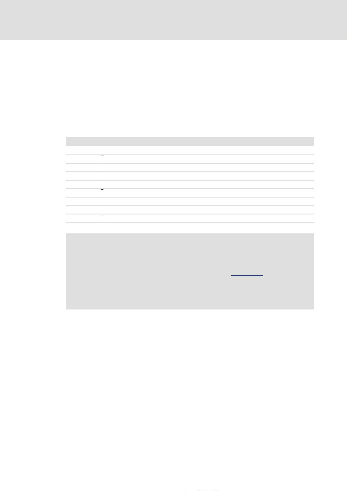
Type of information Writing Examples/notes
Numbers
Decimal separator Point The decimal point is always used.
Example: 1234.56
Text
Program name » « The Lenze PC software »Engineer«...
Window pane Italics The Message window... / The Options dialog box...
Control element Bold The OK button... / The Copy command... / The
Sequence of menu
commands
Keyboard command <Bold> Use <F1> to open the Online Help.
Program listings Courier
Keyword Courier bold
Properties tab... / The Name input field...
If the execution of a function requires several
commands, the individual commands are separated
by an arrow: Select File
If a command requires a combination of keys, a "+" is
placed between the key symbols:
Use <Shift>+<ESC> to...
IF var1 < var2 THEN
a = a + 1
END IF
Open to...
Hyperlink Underlined
Symbols
Page reference ( 6) Optically highlighted reference to another page. It is
Step-by-step instructions
Optically highlighted reference to another topic. It is
activated with a mouse click in this online
documentation.
activated with a mouse click in this online
documentation.
Step-by-step instructions are indicated by a
pictograph.
6 L EDS94AYFLF EN 3.2 - 10/2010
Page 7

Digital frequency extension module | Parameter setting & configuration
1.2 Terminology used
Term Meaning
»Engineer« Lenze software which supports you throughout the whole machine life
Code "Container" for one or several parameters used for controller parameter
Subcode If a code contains several parameters, the individual parameters are
Function block A function block (FB) can be compared with an integrated circuit that
System block System blocks provide interfaces to basic functions and hardware of the
About this documentation
Terminology used
cycle - from planning to maintenance.
setting or monitoring.
stored under "subcodes".
This Manual uses a slash "/" as a separator between code and subcode
(e.g. "C00118/3").
contains a certain control logic and delivers one or several values when
being executed.
• An instance (reproduction, copy) of the function block is always
inserted in the circuit.
• It is also possible to insert several instances of a function block in a
circuit.
• Each instance has a unique identifier (the instance name) and a
processing number which defines the position at which the function
block is calculated during the task cycle.
controller in the function block editor of the »Engineer« (e.g. to the
digital inputs).
• System blocks cannot be instanced in contrast to function blocks.
EDS94AYFLF EN 3.2 - 10/2010 L 7
Page 8

Digital frequency extension module | Parameter setting & configuration
About this documentation
Definition of notes used
1.3 Definition of notes used
The following signal words and symbols are used in this documentation to indicate
dangers and important information:
Safety instructions
Layout of the safety instructions:
Danger!
(characterises the type and severity of danger)
Note
(describes the danger and gives information about how to prevent dangerous
situations)
Pictograph Signal word Meaning
Danger! Danger of personal injury through dangerous electrical voltage
Danger! Danger of personal injury through a general source of danger
Application notes
Pictograph Signal word Meaning
Stop! Danger of material damage
Note! Important note for trouble-free operation
Indicates an impending danger that may lead to death or severe personal injury
if the corresponding measures are not taken.
Indicates an impending danger that may lead to death or severe personal injury
if the corresponding measures are not taken.
Indicates a potential danger that may lead to material damage if the
corresponding measures are not taken.
Tip! Useful tip for easy handling
Reference to another document
8 L EDS94AYFLF EN 3.2 - 10/2010
Page 9
Digital frequency extension module | Parameter setting & configuration
2 Digital frequency input
The optionally available digital frequency extension module serves to extend the L-force
9400 Servo Drive by a digital frequency input and a digital frequency output.
The digital frequency input X9 reads encoder signals with TTL level (0 ... 500 kHz) and
converts these to scaled speed and position values for the application.
2.1 Terminal assignment X9
Pin Signal
1B
2A
3A
4 +5 V encoder voltage (controlled)
5GND
6Z
7Z
8 Sense / Lamp control / Enable
9B
Digital frequency input
Terminal assignment X9
Stop!
If an encoder is connected to X9 and supplied by the digital frequency extension
module "in a controlled way", the pin 8 of the digital frequency input X9 serves
to control and monitor the +5 V encoder voltage. Monitoring
In this case, no digital signal ("Lamp control" or "Enable") may be supplied to PIN
8!
Please also observe the documentation for the encoder used.
EDS94AYFLF EN 3.2 - 10/2010 L 9
Page 10
Digital frequency extension module | Parameter setting & configuration
Digital frequency input
Parameter setting
2.2 Parameter setting
Note!
Depending on the module receptacle the digital frequency extension module is
plugged in, different code ranges are assigned to the parameters!
• Module receptacle MXI1: Parameters are in the C130xx range
• Module receptacle MXI2: Parameters are in the C140xx range
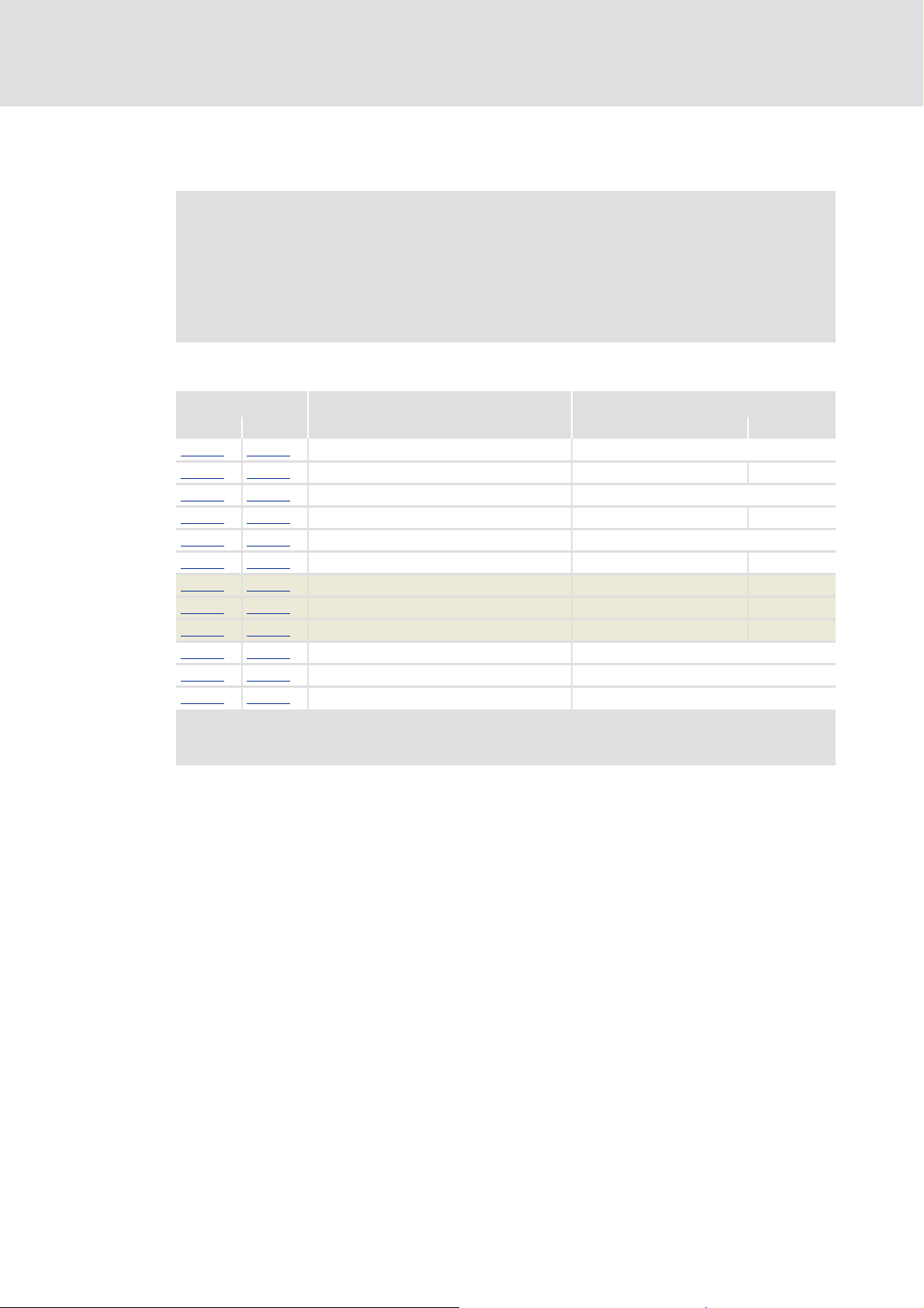
Short overview of the parameters for the digital frequency input:
Parameter Info Lenze setting
C13010 C14010 Encoder type DFIN Digital frequency output DFOUT
C13011
C13012
C13013
C13014
C13021
C13030 C14030 Speed at DFIN - Incr./ms
C13031 C14031 Frequency at DFIN - Hz
C13032 C14032 Position at DFIN - Increments
C13040
C13041
C13042
Digital frequency extension module in module receptacle MXI1
Digital frequency extension module in module receptacle MXI2
Greyed out = display parameter
C14011 No. of increments DFIN 2048
C14012 Signal form DFIN 4x evaluation (A, B)
C14013 Initialisation time DFIN 3000 ms
C14014 Track monitoring DFIN Active after initialisation time
C14021 TP delay time DFIN 0 μs
C14040 Resp. to track monitoring DFIN Warning
C14041 No resp. to DFIN enable signal Warning
C14042 Resp. to Vcc error DFIN Warning
Value Unit
10 L EDS94AYFLF EN 3.2 - 10/2010
Page 11
Digital frequency extension module | Parameter setting & configuration
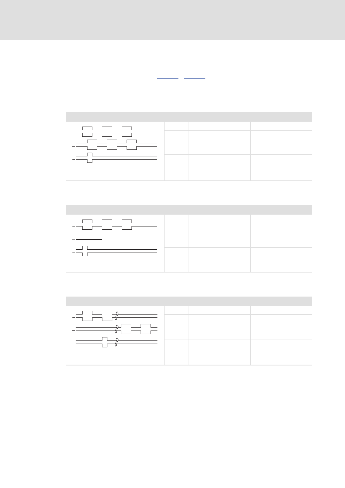
2.2.1 Signal form configuration
In order that the input signals are interpreted correctly from the digital frequency
extension module, the setting in C13012
the input signals applied:
4x evaluation (A, B)
Setting C13012 / C14012 = "0"
A
A
B
B
Z
Z
Phase-displaced signal sequence (CW
rotation)
Digital frequency input
Parameter setting
/ C14012 must correspond to the signal form of
CW rotation CCW rotation
Track A leads track B by 90° lags track B by 90°
Track B --
A:Increments B:Sign
Setting C13012 / C14012 = "1"
A
A
B
B
Z
Z
Control of the direction of rotation via track B
Increments A:pos. B:neg.
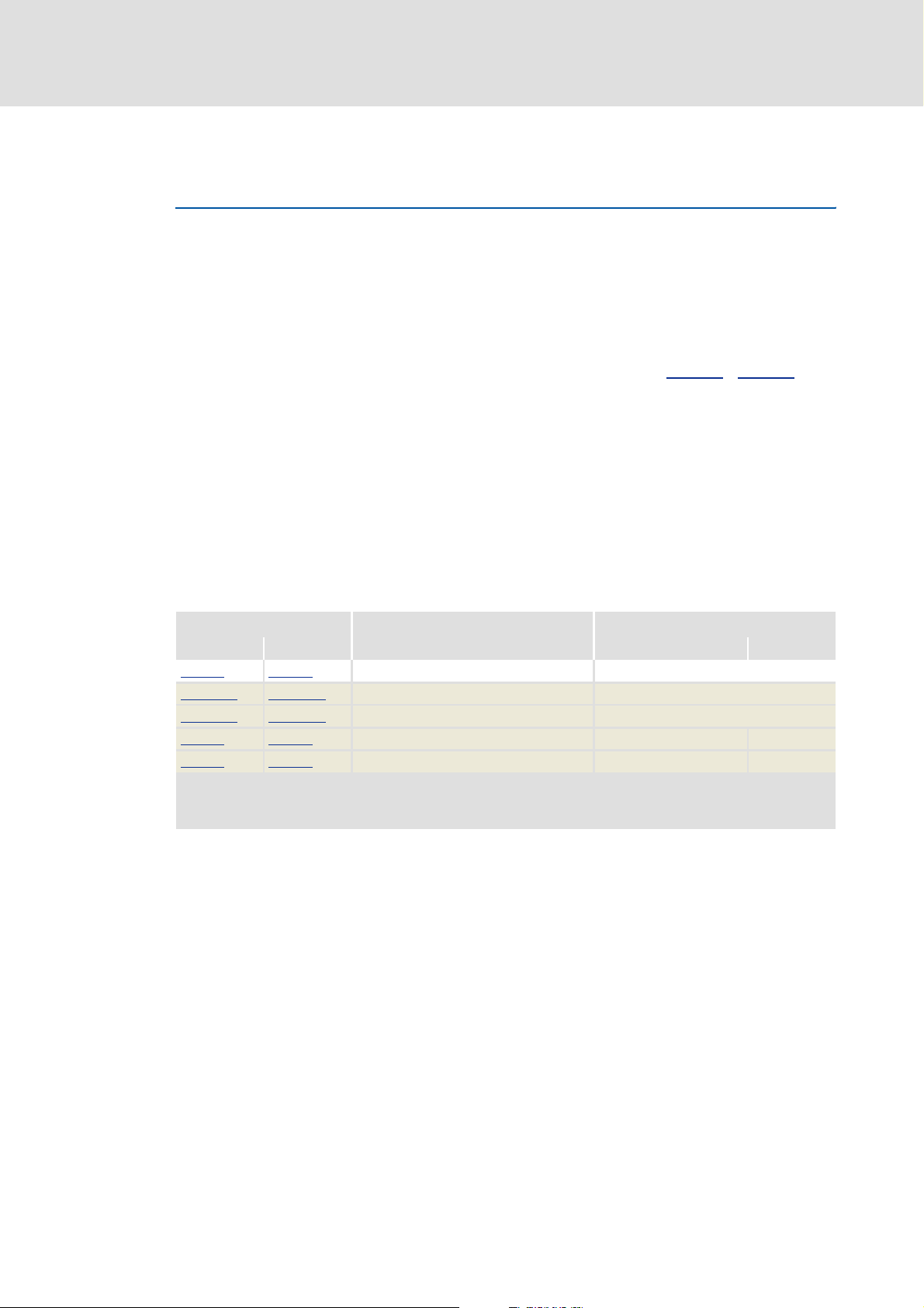
Setting C13012 / C14012 = "2"
A
A
B
B
Z
Z
Control of speed and direction of rotation via
track A or track B
CW rotation CCW rotation
Track A transmits the speed transmits the speed
Track B = FALSE = TRUE
CW rotation CCW rotation
Track A transmits speed and
direction of rotation
Track B = FALSE transmits speed and
= FALSE
direction of rotation
EDS94AYFLF EN 3.2 - 10/2010 L 11
Page 12

Digital frequency extension module | Parameter setting & configuration
Digital frequency input
Parameter setting
2.2.2 Encoder signal detection
From the encoder signals applied to digital frequency input X9 and the number of
increments set in C13011
application via the output DFIN_nActualSpeed_s of the system block
LS_DigitalFrequencyInput.
At the same time the detected speed is integrated to a 32-bit absolute position and
provided to the application via the output DFIN_dnActualPos_p of the system block
LS_DigitalFrequencyInput.
See also: Problem description - speed variations ( 17)
2.2.3 Position setting
The 32-bit absolute position output by the system block LS_DigitalFrequencyInput at the
output DFIN_dnActualPos_p can be set as follows to a certain position value:
1. Define the desired absolute position at the input DFIN_dnReferencePos_p in
[increments].
/ C14011 the speed is created in [rpm] and provided to the
2. Set the input DFIN_bLoadReferencePos from FALSE to TRUE to accept the defined
position for the digital frequency input in the next cycle.
Note!
The speed is not affected by setting the position.
If the speed is integrated in the application, the integrator and the position
assume different values, i.e. they diverge. In case of further position changes, the
difference between the values remains the same.
12 L EDS94AYFLF EN 3.2 - 10/2010
Page 13
Digital frequency extension module | Parameter setting & configuration
2.2.4 Use of machine parameters for scaling
This function extension is available from software version V3.0 onwards!
The input DFIN_AxisData can be used to transfer the machine parameters of the own
motor/drive or of a higher-level drive to the system block LS_DigitalFrequencyInput.
If valid machine parameters are applied to the input DFIN_AxisData, then the outputs
for the actual position and the actual speed are evaluated on the basis of the
transferred machine parameters (gearbox factors, encoder resolution).
– The position is scaled to the set measuring system/traversing range.
– The encoder mounting position can be parameterised under C13015
If the input DFIN_AxisData remains unused, the system block continues to operate as
before. In this case the units are scaled to revolutions.
Tip!
Digital frequency input
Parameter setting
/ C14015.
With this function extension, the system block LS_DigitalFrequencyInput can be
coupled directly to a master value measuring system. The system block then uses
the units of this measuring system for processing.
Short overview of the parameters for this function extension:
Parameter Info Lenze setting
C13015 C14015 Encoder mounting position DFIN Clockwise rotation
C13035/1 C14035/1 Position unit DFIN -
C13035/2 C14035/2 Speed unit DFIN -
C13036 C14036 Actual position DFIN - Unit
C13037 C14037 Actual speed DFIN - Unit/t
Digital frequency extension module in module receptacle MXI1
Digital frequency extension module in module receptacle MXI2
Greyed out = display parameter
Value Unit
EDS94AYFLF EN 3.2 - 10/2010 L 13
Page 14

Digital frequency extension module | Parameter setting & configuration
Digital frequency input
Parameter setting
2.2.5 Voltage control - TTL encoder
If a TTL encoder is connected as the signal source and C13010
encoder, the encoder can be supplied with a controlled +5 V voltage via pin 4, which serves
to compensate the voltage drop on the encoder cable.
Stop!
2.2.6 Monitoring
Initialisation time
In C13013
system before the monitoring modes are switched active.
Thanks to this "delay" other system parts which serve as signal sources, can initialise
themselves first without monitoring being triggered due to missing signals.
In the "0" setting the initialisation time is set to infinity so that monitoring is
deactivated permanently.
/ C14010 is set to TTL
If an encoder is connected to X9 and supplied by the digital frequency extension
module "in a controlled way", the pin 8 of the digital frequency input X9 serves
to control and monitor the +5 V encoder voltage. Monitoring
In this case, no digital signal ("Lamp control" or "Enable") may be supplied to PIN
8!
Please also observe the documentation for the encoder used.
/ C14013 an initialisation time can be set, which must elapse after starting the
If the setting is changed from "0" to another value, the initialisation time is restarted.
– A higher-level control can, for instance, switch monitoring active by a corresponding
parameter setting of C13013
long time.
Monitoring of the +5 V voltage for the encoder
If an encoder is connected to X9 and supplied by the digital frequency extension module
"in a controlled way", the pin 8 of the digital frequency input X9 serves to control and
monitor the +5 V encoder voltage.
If the voltage control is not able to compensate the voltage drop, a fault message is
created and the response set in C13042
– At the same time the output DFIN_bVccCtrlLimited of the system block
LS_DigitalFrequencyInput is set to TRUE.
/ C14013 even if the device has been switched on for a
/ C14042 is executed.
14 L EDS94AYFLF EN 3.2 - 10/2010
Page 15
Digital frequency extension module | Parameter setting & configuration
Digital frequency input
Parameter setting
Monitoring of the "Enable" or "Lamp control" signal
If the +5 V encoder voltage is not controlled by the digital frequency extension module, a
digital signal can be read in and monitored via pin 8 of the digital frequency input X9, e.g.
the "Lamp control" signal of an encoder or the "Enable" signal of an upstream digital
frequency module.
If pin 8 of the digital frequency input X9 is not set to HIGH level (+5V) after the
initialisation time has elapsed, a fault message is generated and the response set in
C13041
The binary status of pin 8 is also displayed at the output DFIN_bSense of the system
block LS_DigitalFrequencyInput .
Track monitoring (open circuit detection)
The signal tracks A, B, and Z are monitored with regard to their differential voltage value.
/ C14041 is executed.
For the activation of track monitoring, two modes are available in C13014
C13014 / C14014 = "1" C13014 / C14014 = "2"
The track monitoring modes are activated after the
initialisation time has elapsed.
• The initialisation time is set in C13013
/ C14013.
The track monitoring modes only become active if pin 8
of the digital frequency input X9 is set to HIGH level
(+5 V).
• They may be activated e.g. by an encoder (status
"Lamp control") or an upstream digital frequency
module (status "Enable").
• When this mode is selected, monitoring can be
switched active by a signal source if the levels on the
tracks have valid values.
/ C14014:
Monitoring is both done at standstill and while the encoder is rotating.
If track monitoring responds, a fault message is generated and the response set in
C13040
/ C14040 is executed.
– At the same time the corresponding output DFIN_bTrackAError, DFIN_bTrackBError
or DFIN_bTrackZError of the system block LS_DigitalFrequencyInput is set to TRUE.
EDS94AYFLF EN 3.2 - 10/2010 L 15
Page 16

Digital frequency extension module | Parameter setting & configuration
Digital frequency input
Parameter setting
2.2.7 Touch probe
When the zero pulse occurs on track Z - Z
The corresponding signals to execute touch probe processing are available via the
system block LS_TouchProbeDFIN.
In C13021
If a touch probe has been triggered, the output DFIN_bTouchProbeReceived is set to
TRUE for one cycle.
/ C14021 a delay time can be set for the touch probe.
, a touch probe is triggered.
Tip!
Detailed information on touch probe processing can be found in the online
documentation for the controller in chapter "I/O terminalsTouch probe
detection".
16 L EDS94AYFLF EN 3.2 - 10/2010
Page 17

Digital frequency extension module | Parameter setting & configuration
2.3 Problem description - speed variations
In the digital frequency extension module rectangular encoder signals are processed. The
speed is determined by counting the edges occurring within a defined time interval (1 ms).
Due to this defined time interval of 1 ms and a finite number of encoder increments per
revolution, the calculated speed signal can only assume discrete values. This gives the
impression that the signal is very unsteady and inexact. This effect increases with lower
numbers of increments.
An example for calculating the expected speed variation can be found in chapter "Digital
frequency output". Problem description - speed variations
Digital frequency input
Problem description - speed variations
( 28)
EDS94AYFLF EN 3.2 - 10/2010 L 17
Page 18

Digital frequency extension module | Parameter setting & configuration
Digital frequency input
System block "LS_DigitalFrequencyInput"
2.4 System block "LS_DigitalFrequencyInput"
The system block LS_DigitalFrequencyInput displays the optional digital frequency
extension module in the FB editor of the »Engineer«.
The system block must be called cyclically since only then speed and position will be
calculated accurately to increments.
/6B'LJLWDO)UHTXHQF\,QSXW
'),1BE/RDG5HIHUHQFH3RV
'),1BGQ5HIHUHQFH3RVBS
'),1B$[LV'DWD
;
'),1BGQ$FWXDO3RVBS
'),1BGQ$FWXDO6SHHGBV
'),1BE7UDFN$(UURU
'),1BE7UDFN%(UURU
'),1BE7UDFN=(UURU
'),1BE6HQVH
'),1BE9FF&WUO/LPLWHG
Inputs
Input
Data type
DFIN_bLoadReferencePos
DFIN_dnReferencePos_p
DFIN_AxisData
V3.0 or higher
Info/possible settings
Position setting
BOOL
Position setting
FALSEÊTRUE Sets the 32-bit absolute position output at the output
Absolute position in [increments], to which the output DFIN_dnActualPos_p is set by
DINT
a FALSE-TRUE edge at input DFIN_bLoadReferencePos.
Position setting
Machine parameters
• To transfer the machine parameters of the drive/motor, connect this input to the
output DI_AxisData of SB LS_DriveInterface.
• The machine parameters of a higher-level drive can be transferred via the
FB L_SdSetAxisData. For this purpose, you have to connect the FB's AxisData
output to this input.
• If the input remains unused, the system block continues to operate as before. In
this case the units are scaled to revolutions.
Use of machine parameters for scaling
( 12)
DFIN_dnActualPos_p to the value which is applied to input
DFIN_dnReferencePos_p.
( 12)
( 13)
18 L EDS94AYFLF EN 3.2 - 10/2010
Page 19

Digital frequency extension module | Parameter setting & configuration
Digital frequency input
System block "LS_DigitalFrequencyInput"
Outputs
Output
DFIN_dnActualPos_p
DFIN_dnActualSpeed_s
DFIN_bTrackAError
DFIN_bTrackBError
DFIN_bTrackZError
DFIN_bSense
DFIN_bVccCtrlLimited
Data type
DINT
DINT
BOOL
BOOL
BOOL
BOOL
BOOL
Value/meaning
Current position in [increments]
• Output as signed 32-bit value (positive value ≡ CW rotation).
For software versions prior to V3.0:
• A virtual revolution is resolved to 16 bits.
For software version V3.0 or higher:
• If valid machine parameters are applied to the input DFIN_AxisData, a virtual
revolution is resolved with the encoder resolution specified in the machine
parameters.
•If the input DFIN_AxisData remains unused, a virtual revolution is resolved with
the setting under C00100 (Lenze setting: 16 bits).
Current speed in [rpm]
Problem description - speed variations
Status signal "Differential signal of track A - A invalid"
Monitoring
Status signal "Differential signal of track B - B invalid"
Monitoring
Status signal "Differential signal of track Z - Z invalid"
Monitoring
Status signal "Enable/Lamp control signal is set"
Monitoring
Status signal "Voltage control for TTL encoder is at the limit"
Voltage control - TTL encoder
( 14)
TRUE The differential signal of track A - A
(open circuit).
( 14)
TRUE The differential signal of track B - B
(open circuit).
( 14)
TRUE The differential signal of track Z - Z
(open circuit).
( 14)
TRUE An upstream digital frequency output has set the "Enable signal"
(HIGH signal at X9, pin 8).
( 14)
TRUE The voltage control for a connected TTL encoder has reached the
limit value.
( 17)
is outside the valid voltage range
is outside the valid voltage range
is outside the valid voltage range
EDS94AYFLF EN 3.2 - 10/2010 L 19
Page 20

Digital frequency extension module | Parameter setting & configuration
Digital frequency input
System block "LS_TouchProbeDFIN"
2.5 System block "LS_TouchProbeDFIN"
The system block LS_TouchProbeDFIN provides the touch probe signals of the digital
frequency input of the optional digital frequency extension module in the FB editor of the
»Engineer«.
The touch probe is triggered when a zero pulse occurs on track Z - Z
In C13021
/ C14021 a delay time can be set for the touch probe.
.
When a touch probe has been triggered, the output DFIN_bTouchProbeReceived is set
to TRUE for one cycle of the task in which the SB is being processed.
/6B7RXFK3UREH'),1
'),1BGQ7RXFK3UREH7LPH/DJ
73
'),1BE7RXFK3UREH5HFHLYHG
'),1BE7RXFK3UREH/RVW
Outputs
Output
DFIN_dnTouchProbeTimeLag
DFIN_bTouchProbeReceived
DFIN_bTouchProbeLost
Data type
Value/meaning
Scaled time stamp for further processing of the touch probe event with the
DINT
FB L_SdTouchProbe.
Status signal "Touch probe detected"
BOOL
• Status is only pending for one cycle of the task in which the SB is being processed.
TRUE Touch probe event has been triggered.
Status signal "Touch probe(s) lost"
BOOL
• Status is only pending for one cycle of the task in which the SB is being processed.
TRUE More than one touch probe event has been triggered within the task
runtime and could therefore not be registered anymore.
Tip!
Detailed information on touch probe processing can be found in the online
documentation for the controller in chapter "I/O terminalsTouch probe
detection".
20 L EDS94AYFLF EN 3.2 - 10/2010
Page 21

Digital frequency extension module | Parameter setting & configuration
3 Digital frequency output
The optionally available digital frequency extension module serves to extend the L-force
9400 Servo Drive by a digital frequency input and a digital frequency output.
The digital frequency output X10 serves to output encoder signals with TTL level
(0 ... 500 kHz).
3.1 Terminal assignment X10
Pin Signal
1B
2A
3A
4+5 V (±6%)
5GND
6Z
7Z
8Enable
9B
Digital frequency output
Terminal assignment X10
EDS94AYFLF EN 3.2 - 10/2010 L 21
Page 22

Digital frequency extension module | Parameter setting & configuration
Digital frequency output
Parameter setting
3.2 Parameter setting
Note!
Depending on the module receptacle the digital frequency extension module is
plugged in, different code ranges are assigned to the parameters!
• Module receptacle MXI1: Parameters are in the C130xx range
• Module receptacle MXI2: Parameters are in the C140xx range
Short overview of the parameters for the digital frequency output:
Parameter Info Lenze setting
C13050 C14050 Signal source DFOUT Application
C13051
C13052
C13053
C13061
C13070 C14070 Speed at DFOUT - Incr./ms
C13071 C14071 Frequency at DFOUT - Hz
C13072 C14072 Position at DFOUT - Increments
C13080
Digital frequency extension module in module receptacle MXI1
Digital frequency extension module in module receptacle MXI2
Greyed out = display parameter
C14051 No. of increments DFOUT 2048
C14052 Zero pulse offset DFOUT 0 Increments
C14053 Frequency limitation DFOUT 500 kHz
C14061 TP delay time DFOUT 0 μs
C14080 Resp. to frequency limit. DFOUT Warning
Value Unit
22 L EDS94AYFLF EN 3.2 - 10/2010
Page 23

Digital frequency extension module | Parameter setting & configuration
3.2.1 Signal source selection
Digital frequency output
Parameter setting
The signal source for the digital frequency output is selected in C13050
DFIN DFOUT
X9 X10
LS_DigitalFrequencyOutput
Application
DFOUT_dnSpeedSet_s
[3-1] Selection of the signal source for X10
Selection Info
1 Digital frequency output is inactive
• "0" frequency is output a the digital frequency output.
• All tracks remain on the level output last.
• After the controller is switched on, the tracks A, B, and Z are set to HIGH level.
2 The digital frequency input X9 is directly connected to the digital frequency output.
Note:
Due to the direct connection between input and output, sensors are no longer required.
• The zero pulse offset (C13052
• The frequency limitation (C13053
• The zero track is only output if connected to X9.
• The display parameters for the actual values (speed, frequency, position) are not updated
(remedy: use display parameters of the digital frequency input).
•The outputs DFOUT_dnActualPos_p and DFOUT_dnActualSpeed_s of the system block
LS_DigitalFrequencyOutput are not updated.
3 Output of the motor encoder
• The angle of rotation in [increments] derived from the motor encoder is output as a frequency
signal after being evaluated with the set number of increments (C13051
• The output signal is integrated to a position value via a counter and made available to the
application via the output DFOUT_dnActualPos_p of the system block
LS_DigitalFrequencyOutput.
4 Output of the load encoder
• The angle of rotation in [increments] derived from the load encoder is output as a frequency
signal after being evaluated with the set number of increments (C13051
• The output signal is integrated to a position value via a counter and made available to the
application via the output DFOUT_dnActualPos_p of the system block
LS_DigitalFrequencyOutput.
5 Output of the resolver angle
• The angle of rotation in [increments] derived from the resolver input is output as a frequency
signal after being evaluated with the set number of increments (C13051
• The output signal is integrated to a position value via a counter and made available to the
application via the output DFOUT_dnActualPos_p of the system block
LS_DigitalFrequencyOutput.
• It is irrelevant for the output whether the resolver input is used as a load encoder, motor encoder,
or not used at all for the motor control.
Motor speed
Load speed
Resolver speed
Encoder speed
1
Off
0
2
3
4
5
6
7
C1 3
4
/ C14052) is without function.
/ C14053) is without function.
050
/ C14050:
1
Off
2
3
4
5
6
7
/ C14051).
/ C14051).
/ C14051).
EDS94AYFLF EN 3.2 - 10/2010 L 23
Page 24

Digital frequency extension module | Parameter setting & configuration
Digital frequency output
Parameter setting
Selection Info
6 Output of the encoder angle
• The angle of rotation in [increments] derived from the encoder input is output as a frequency
signal after being evaluated with the set number of increments (C13051
• The output signal is integrated to a position value via a counter and made available to the
application via the output DFOUT_dnActualPos_p of the system block
LS_DigitalFrequencyOutput.
• It is irrelevant for the output whether the encoder input is used as a load encoder, motor encoder,
or not used at all for the motor control.
7 Output of a speed signal of the application
• The speed signal in [rpm] defined via the input DFOUT_dnSpeedSet_s of the system block
LS_DigitalFrequencyOutput is integrated and output as a frequency signal after being evaluated
with the set number of increments (C13051
• The output signal is integrated to a position value via a counter and made available to the
application via the output DFOUT_dnActualPos_p of the system block
LS_DigitalFrequencyOutput.
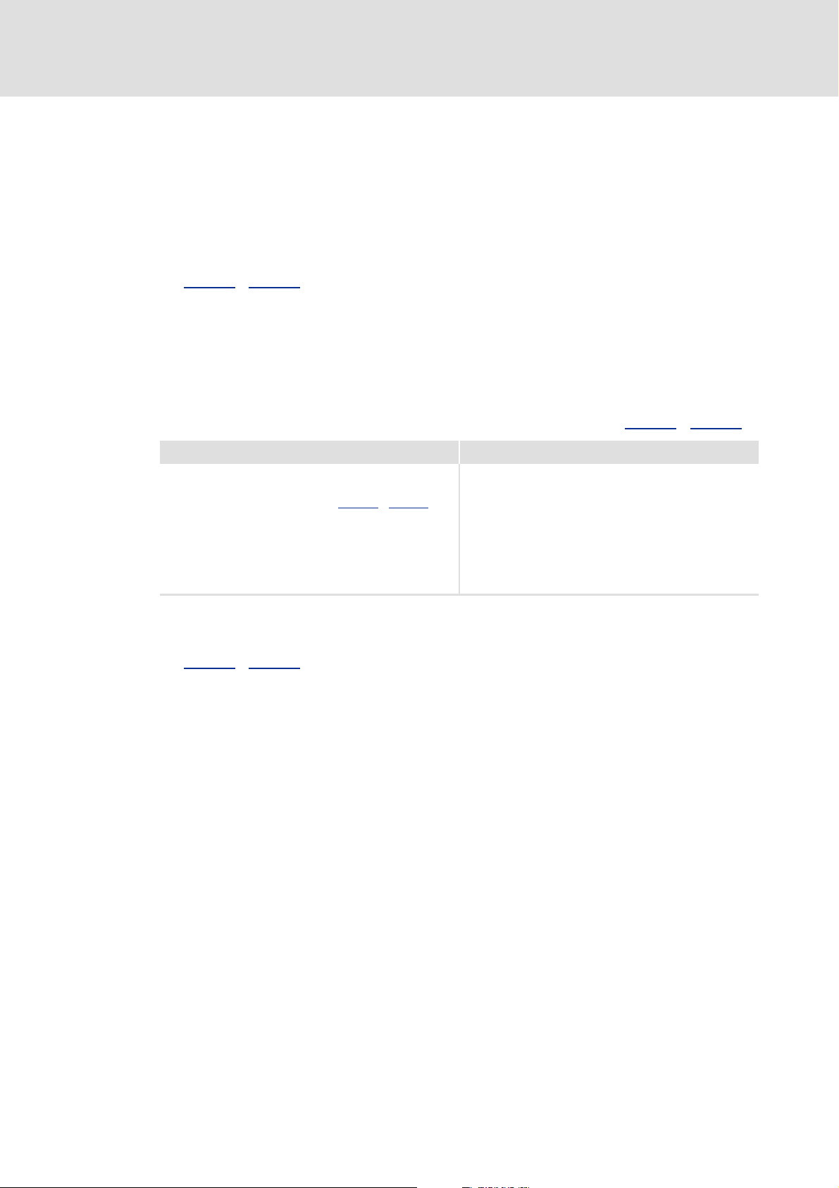
3.2.2 Number of increments and zero pulse offset
/ C14051).
/ C14051).
The number of increments set in C13051
/ C14051 defines e.g. the number of increment to
be output before a zero pulse is created.
Each zero pulse defines a covered "revolution" of the rotary transducer simulated by the
digital frequency output.
Within such a "revolution" (in the value range 0 ... 65535 increments) the zero pulse can
be shifted by setting a zero pulse offset in C13052
/ C14052.
A connection between absolute position and "revolution" is defined by setting the position,
as described in the following chapter "Position setting
". The position of a zero pulse within
a "revolution" remains unchanged.
Example - signal characteristic:
[Inc]
65535
39321
0
n Absolute position (DFOUT_dnActualPos_p, also takes into account each overflow of the encoder position)
o Position difference (is determined by Position setting
p Encoder position (in the value range 0 ... 65535 increments)
q Zero pulse offset (adjustable in C13052
r Zero pulses
DFOUT_dnActualPos_p
t
t
)
/ C14052)
[3-2] Example: Signal characteristic with the zero pulse offset set to 39321 increments
24 L EDS94AYFLF EN 3.2 - 10/2010
Page 25

Digital frequency extension module | Parameter setting & configuration
3.2.3 Position setting
The digital frequency output provides a 32-bit absolute position for the application via the
output DFOUT_dnActualPos_p. This absolute position is created by integrating the
frequency signal to be output.
This position can be set as follows via the system block LS_DigitalFrequencyOutput :
1. Define the desired absolute position at the input DFOUT_dnReferencePos_p in
[increments].
2. Set the input DFOUT_bLoadReferencePos from FALSE to TRUE to accept the defined
position for the digital frequency output in the next cycle.
Note!
The speed is not affected by setting the position.
If the speed is integrated in the application, the integrator and the position
assume different values, i.e. they diverge. In case of further position changes, the
difference between the values remains the same.
Digital frequency output
Parameter setting
EDS94AYFLF EN 3.2 - 10/2010 L 25
Page 26

Digital frequency extension module | Parameter setting & configuration
Digital frequency output
Parameter setting
3.2.4 Use of machine parameters for scaling
This function extension is available from software version V3.0 onwards!
The input DFOUT_AxisData can be used to transfer the machine parameters of the own
motor/drive or of a higher-level drive to the system block LS_DigitalFrequencyOutput.
If valid machine parameters are applied to the input DFOUT_AxisData, then the
outputs for the actual position and the actual speed are evaluated on the basis of the
transferred machine parameters (gearbox factors, encoder resolution) and the position
is scaled to the set measuring system/traversing range.
If the input DFOUT_AxisData remains unused, the system block continues to operate as
before. In this case the units are scaled to revolutions.
Tip!
With this function extension, the system block LS_DigitalFrequencyOutput can be
coupled directly to a master value measuring system. The system block then uses
the units of this measuring system for processing.
Short overview of the parameters for this function extension:
Parameter Info Lenze setting
C13075/1 C14075/1 Position unit DFOUT -
C13075/2 C14075/2 Speed unit DFOUT -
C13076 C14076 Actual position DFOUT - Unit
C13077 C14077 Actual speed DFOUT - Unit/t
Digital frequency extension module in module receptacle MXI1
Digital frequency extension module in module receptacle MXI2
Greyed out = display parameter
Value Unit
26 L EDS94AYFLF EN 3.2 - 10/2010
Page 27

Digital frequency extension module | Parameter setting & configuration
3.2.5 Frequency limitation
Digital frequency output
Parameter setting
In C13053
If the frequency is limited, a fault message is generated and the response set in C13080
/ C14080
– At the same time the output DFOUT_bOutputFreqLimited of the system block
The hardware limits the digital frequency output to 500 kHz.
/ C14053 a frequency limitation can be set for the digital frequency output.
LS_DigitalFrequencyOutput is set to TRUE.
Note!
• Due to the remainder processing implemented in the 4 kHz control cycle, only
settings ≥ 4 kHz are reasonable for frequency limitation!
• If the digital frequency input is directly connected to the digital frequency
output, the set frequency limitation is without function!
3.2.6 Touch probe
When the zero pulse occurs on track Z - Z
The corresponding signals to execute touch probe processing are available via the
system block LS_TouchProbeDFOUT.
In C13061
is executed.
, a touch probe is triggered.
/ C14061 a delay time can be set for the touch probe.
If a touch probe has been triggered, the output DFOUT_bTouchProbeReceived is set to
TRUE for one cycle.
Tip!
Detailed information on touch probe processing can be found in the online
documentation for the controller in chapter "I/O terminalsTouch probe
detection".
EDS94AYFLF EN 3.2 - 10/2010 L 27
Page 28

Digital frequency extension module | Parameter setting & configuration
Digital frequency output
Problem description - speed variations
3.3 Problem description - speed variations
In the digital frequency extension module rectangular encoder signals are processed. The
speed is determined by counting the edges occurring within a defined time interval (1 ms).
Due to this defined time interval of 1 ms and a finite number of encoder increments per
revolution, the calculated speed signal can only assume discrete values. This gives the
impression that the signal is very unsteady and inexact. This effect increases with lower
numbers of increments.
Example for the digital frequency output
An encoder with 2048 increments at a speed of 60 rpm is to be simulated.
Setpoint speed n_set
= 60 rpm = 1 Hz
DFOUT
mech.
Simulated encoder: 2048 increments
(by fourfold evaluation 4 * 2048 = 8192 edges are counted per revolution)
Output frequency = n_set
* number of increments
DFOUT
DFOUT
=1Hz
mech.
* 2048
= 2048 Hz
If the measurement lasts 1 ms, 8.192 edges occur per ms. Since the count can only be an
integer, 8 or 9 increments are counted. Thus, the speed is calculated as follows:
8
n
measure_1
n
measure_2
60 rpm
60 rpm
--------------
⋅ 58.59 rpm==
8.192
or
9
--------------
⋅ 65.91 rpm==
8.192
The speed variation which is detected during this process amounts to:
Δn
measure
n
measure_2nmeasure_1
– 7.32 rpm==
General formula for calculating the expected speed variation
Δn
measure
28 L EDS94AYFLF EN 3.2 - 10/2010
--------------------------------------------------------- -
number of increments
15000
rpm=
Page 29

Digital frequency extension module | Parameter setting & configuration
3.4 System block "LS_DigitalFrequencyOutput"
The system block LS_DigitalFrequencyOutput displays the digital frequency output of the
optional extension module in the FB editor of the »Engineer«:
/6B'LJLWDO)UHTXHQF\2XWSXW
')287BGQ6SHHG6HWBV
' BE/RDG5HIHUHQFH3RV)287
')287BGQ5HIHUHQFH3RVBS
')287B$[LV'DWD
Inputs
Digital frequency output
System block "LS_DigitalFrequencyOutput"
' BGQ$FWXDO3RVBS)287
' BGQ$FWXDO6SHHGBV)287
' BE2XWSXW)UHT/LPLWHG)287
;
Input
Data type
DFOUT_dnSpeedSet_s
DINT
DFOUT_bLoadReferencePos
BOOL
DFOUT_dnReferencePos_p
DINT
DFOUT_AxisData
V3.0 or higher
Info/possible settings
Speed in [rpm], which is to be output via the digital frequency output as encoder
signals with TTL level.
• To select this signal source, C13050
Signal source selection
Position setting
Position setting
FALSEÊTRUE Sets the 32-bit absolute position output at the output
DFOUT_dnActualPos_p to the value which is applied to input
DFOUT_dnReferencePos_p.
Absolute position in [increments], to which the output DFOUT_dnActualPos_p is set
by a FALSE-TRUE edge at input DFOUT_bLoadReferencePos.
Position setting
Machine parameters
• To transfer the machine parameters of the drive/motor, connect this input to the
output DI_AxisData of SB LS_DriveInterface.
• The machine parameters of a higher-level drive can be transferred via the
FB L_SdSetAxisData. For this purpose, you have to connect the FB's AxisData
output to this input.
• If the input remains unused, the system block continues to operate as before. In
this case the units are scaled to revolutions.
Use of machine parameters for scaling ( 26)
( 23)
( 25)
( 25)
/ C14050 = "7" must be set.
EDS94AYFLF EN 3.2 - 10/2010 L 29
Page 30

Digital frequency extension module | Parameter setting & configuration
Digital frequency output
System block "LS_DigitalFrequencyOutput"
Outputs
Output
Data type
DFOUT_dnActualPos_p
DINT
DFOUT_dnActualSpeed_s
DINT
DFOUT_bOutputFreqLimited
BOOL
Value/meaning
Current position as signed 32-bit value in [increments]
For software versions prior to V3.0:
• A virtual revolution is resolved to 16 bits.
For software version V3.0 or higher:
• If valid machine parameters are applied to the input DFOUT_AxisData, a virtual
revolution is resolved with the encoder resolution specified in the machine
parameters.
•If the input DFOUT_AxisData remains unused, a virtual revolution is resolved
with the setting under C00100 (Lenze setting: 16 bits).
Current speed in [rpm]
Problem description - speed variations
Status signal "Frequency to be output is limited"
Frequency limitation
TRUE The frequency to be output is limited by the value set in C13053
C14053
( 27)
.
( 28)
/
30 L EDS94AYFLF EN 3.2 - 10/2010
Page 31

Digital frequency extension module | Parameter setting & configuration
3.5 System block "LS_TouchProbeDFOUT"
The system block LS_TouchProbeDFOUT provides the touch probe signals of the digital
frequency output of the optional digital frequency extension module in the FB editor of the
»Engineer«.
Digital frequency output
System block "LS_TouchProbeDFOUT"
The touch probe is triggered when a zero pulse occurs on track Z - Z
In C13061
/ C14061 a delay time can be set for the touch probe.
.
When a touch probe has been triggered, the output DFOUT_bTouchProbeReceived is set
to TRUE for one cycle of the task in which the SB is being processed.
/6B7RXFK3UREH')287
'),1BGQ7RXFK3UREH7LPH/DJ
73
'),1BE7RXFK3UREH5HFHLYHG
'),1BE7RXFK3UREH/RVW
Outputs
Output
Data type
DFIN_dnTouchProbeTimeLag
DFOUT_
bTouchProbeReceived
DFOUT_bTouchProbeLost
Value/meaning
Scaled time stamp for further processing of the touch probe event with the
DINT
FB L_SdTouchProbe.
Status signal "Touch probe detected"
• Status is only pending for one cycle of the task in which the SB is being processed.
BOOL
Status signal "Touch probe(s) lost"
BOOL
• Status is only pending for one cycle of the task in which the SB is being processed.
TRUE Touch probe event has been triggered.
TRUE More than one touch probe event has been triggered within the task
runtime and could therefore not be registered anymore.
Tip!
Detailed information on touch probe processing can be found in the online
documentation for the controller in chapter "I/O terminalsTouch probe
detection".
EDS94AYFLF EN 3.2 - 10/2010 L 31
Page 32

Digital frequency extension module | Parameter setting & configuration
Parameter reference
Parameter list
4 Parameter reference
Note!
This chapter completes the parameter list and attribute table in the online
documentation for the controller by parameters of the digital frequency
extension module.
Tip!
General information on parameters can be found in the online documentation for
the controller.
4.1 Parameter list
This chapter contains all parameters of the digital frequency extension module in
numerically ascending order.
Abbreviated units
Abbreviation Meaning
Incr. Increments
32 L EDS94AYFLF EN 3.2 - 10/2010
Page 33

Digital frequency extension module | Parameter setting & configuration
Parameter reference
Parameter list | C13010
C13010
C13011
C13012
Parameter | Name:
C13010 | Encoder type DFIN
Digital frequency extension module in module receptacle MXI1:
Selection of the encoder type for digital frequency input X9
Selection list
(Lenze setting in bold)
1 Digital frequency output DFOUT
2 TTL encoder
; Read access ; Write access CINH PLC-STOP No transfer
Parameter | Name:
C13011 | No. of increments DFIN
Digital frequency extension module in module receptacle MXI1:
Number of increments for digital frequency input X9
• Definition of the number of pulses for one "mechanical" revolution.
Setting range
(min. value | unit | max. value) Lenze setting
1 16384 2048
; Read access ; Write access CINH PLC-STOP No transfer
Parameter | Name:
C13012 | Signal format DFIN
Digital frequency extension module in module receptacle MXI1:
Signal form for digital frequency input X9
• Selection of how to interpret the input signal.
Selection list
(Lenze setting in bold)
04x evaluation (A, B)
1 A:Increments B:Sign
2 Increments A:pos. B:neg.
; Read access ; Write access CINH PLC-STOP No transfer
Data type: UNSIGNED_8
Index: 11565
Data type: UNSIGNED_32
Index: 11564
Data type: UNSIGNED_8
Index: 11563
= 2D2D
d
= 2D2C
d
= 2D2B
d
h
h
h
C13013
C13014
Parameter | Name:
C13013 | Initialisation time DFIN
Data type: UNSIGNED_16
Index: 11562
= 2D2A
d
Digital frequency extension module in module receptacle MXI1:
Initialisation time for digital frequency input X9
• Waiting time after which the "Enable" signal is evaluated and the track monitoring modes are switched active.
Setting range
(min. value | unit | max. value) Lenze setting
0 ms 65535 3000 ms
; Read access ; Write access CINH PLC-STOP No transfer
Parameter | Name:
C13014 | Track monitoring DFIN
Data type: UNSIGNED_8
Index: 11561
= 2D29
d
Digital frequency extension module in module receptacle MXI1:
Monitoring configuration for digital frequency input X9
• Selection when track monitoring modes (open circuit detection) are active.
Selection list
(Lenze setting in bold)
1 Active after initialisation time
2 Active after enable signal
; Read access ; Write access CINH PLC-STOP No transfer
h
h
EDS94AYFLF EN 3.2 - 10/2010 L 33
Page 34

Digital frequency extension module | Parameter setting & configuration
Parameter reference
Parameter list | C13015
C13015
C13021
C13030
C13031
Parameter | Name:
C13015 | Encoder mounting dir. (DFIN)
Data type: UNSIGNED_32
Index: 11560
= 2D28
d
Selection list (Lenze setting in bold) Info
0 Clockwise direction of rotation
1 Counter-clockwise direction of
rotation
; Read access ; Write access ; CINH PLC-STOP No transfer
Parameter | Name:
C13021 | TP delay time DFIN
Data type: UNSIGNED_32
Index: 11554
= 2D22
d
Digital frequency extension module in module receptacle MXI1:
Touch probe delay for digital frequency input X9
• The delay time set is considered when the position at the instant of touch probe is determined (instant of zero
pulse) and serves to compensate dead times, if existent.
Setting range
(min. value | unit | max. value) Lenze setting
0 μs 7000 0 μs
; Read access ; Write access CINH PLC-STOP No transfer
Parameter | Name:
C13030 | Speed at DFIN
Data type: INTEGER_32
Index: 11545
= 2D19
d
Digital frequency extension module in module receptacle MXI1:
Display of the current speed at digital frequency input X9
Display range
(min. value | unit | max. value)
-2147483648 Incr./ms 2147483647
; Read access Write access CINH PLC-STOP No transfer
Parameter | Name:
C13031 | Frequency at DFIN
Data type: INTEGER_32
Index: 11544
= 2D18
d
Digital frequency extension module in module receptacle MXI1:
Display of the current frequency at digital frequency input X9
Display range
(min. value | unit | max. value)
-2147483648 Hz 2147483647
; Read access Write access CINH PLC-STOP No transfer
h
h
h
h
C13032
Parameter | Name:
C13032 | Position at DFIN
Data type: INTEGER_32
Index: 11543
= 2D17
d
Digital frequency extension module in module receptacle MXI1:
Display of the current position at digital frequency input X9
Display range
(min. value | unit | max. value)
-2147483648 Incr. 2147483647
; Read access Write access CINH PLC-STOP No transfer
C13035
Parameter | Name:
C13035 | Unit
Data type: VISIBLE_STRING
Index: 11540
= 2D14
d
Subcodes Info
C13035/1 Unit for the position
C13035/2 Unit for the speed
; Read access Write access CINH PLC-STOP No transfer
34 L EDS94AYFLF EN 3.2 - 10/2010
h
h
Page 35

Digital frequency extension module | Parameter setting & configuration
Parameter reference
Parameter list | C13036
C13036
C13037
C13040
Parameter | Name:
C13036 | Actual position DFIN
Display range (min. value | unit | max. value)
-214748.3647 Unit 214748.3647
; Read access Write access CINH PLC-STOP No transfer Scaling factor: 10000
Parameter | Name:
C13037 | Actual speed DFIN
Display range (min. value | unit | max. value)
-214748.3647 Unit/s 214748.3647
; Read access Write access CINH PLC-STOP No transfer Scaling factor: 10000
Parameter | Name:
C13040 | Resp. to track monitoring DFIN
Digital frequency extension module in module receptacle MXI1:
Response when track monitoring is triggered for digital frequency input X9
• Track monitoring is triggered if a signal cable (A, B, or Z) is interrupted.
Selection list
(Lenze setting in bold)
1Fault
2Trouble
3 Quick stop by trouble
5 Warning
4 Warning locked
6 Information
0 No response
; Read access ; Write access CINH PLC-STOP No transfer
Data type: INTEGER_32
Index: 11539
Data type: INTEGER_32
Index: 11538
Data type: UNSIGNED_8
Index: 11535
= 2D13
d
= 2D12
d
= 2D0F
d
h
h
h
C13041
Parameter | Name:
C13041 | Resp. to DFIN enable sig. miss.
Digital frequency extension module in module receptacle MXI1:
Response when "Enable" signal at digital frequency input X9 fails
Selection list
(Lenze setting in bold)
1Fault
2Trouble
3 Quick stop by trouble
5 Warning
4 Warning locked
6 Information
0 No response
; Read access ; Write access CINH PLC-STOP No transfer
Data type: UNSIGNED_8
Index: 11534
= 2D0E
d
h
EDS94AYFLF EN 3.2 - 10/2010 L 35
Page 36

Digital frequency extension module | Parameter setting & configuration
Parameter reference
Parameter list | C13042
C13042
C13050
Parameter | Name:
C13042 | Resp. to Vcc error DFIN
Data type: UNSIGNED_8
Index: 11533
= 2D0D
d
Digital frequency extension module in module receptacle MXI1:
Response when monitoring for encoder voltage supply at digital frequency input X9 is triggered
• Monitoring is triggered if the encoder voltage controlled by the digital frequency input reaches the voltage limit.
Selection list
(Lenze setting in bold)
1Fault
2Trouble
3 Quick stop by trouble
5 Warning
4 Warning locked
6 Information
0 No response
; Read access ; Write access CINH PLC-STOP No transfer
Parameter | Name:
C13050 | Signal source DFOUT
Data type: UNSIGNED_8
Index: 11525
= 2D05
d
Digital frequency extension module in module receptacle MXI1:
Selection of the signal source for digital frequency output X10
Selection list
(Lenze setting in bold)
1None
2 Digital frequency input DFIN
3 Motor feedback system
4 Load feedback system
5Resolver
6Encoder
7Application [Incr./ms]
; Read access ; Write access CINH PLC-STOP No transfer
h
h
C13051
C13052
Parameter | Name:
C13051 | No. of increments DFOUT
Digital frequency extension module in module receptacle MXI1:
Number of increments for digital frequency output X10
• Definition of the number of pulses for one "mechanical" revolution.
Setting range
(min. value | unit | max. value) Lenze setting
1 16384 2048
; Read access ; Write access CINH PLC-STOP No transfer
Parameter | Name:
C13052 | Zero pulse offset DFOUT
Digital frequency extension module in module receptacle MXI1:
Zero pulse offset for digital frequency output X10
• Offset for displacing the zero pulse to be output.
Setting range
(min. value | unit | max. value) Lenze setting
0 Incr. 65535 0increments
; Read access ; Write access ; CINH PLC-STOP No transfer
Data type: UNSIGNED_32
Index: 11524
Data type: UNSIGNED_16
Index: 11523
= 2D04
d
= 2D03
d
h
h
36 L EDS94AYFLF EN 3.2 - 10/2010
Page 37

Digital frequency extension module | Parameter setting & configuration
Parameter reference
Parameter list | C13053
C13053
C13061
Parameter | Name:
C13053 | Frequency limitation DFOUT
Data type: UNSIGNED_16
Index: 11522
= 2D02
d
Digital frequency extension module in module receptacle MXI1:
Limit frequency for digital frequency output X10
• Frequency to which the digital frequency output is limited by the software.
• If the limit value is reached, the response set in C13080
is executed.
• In terms of the hardware, the digital frequency output is limited to 500 kHz.
• If the digital frequency input is directly connected to the digital frequency output, the set frequency limitation
is functionless!
Note: Du to the remainder processing implemented in the 4 kHz control cycle, only settings ≥ 4 kHz are reasonable
for frequency limitation!
Frequency limitation
Setting range (min. value | unit | max. value) Lenze setting
1 kHz 500 500 kHz
; Read access ; Write access CINH PLC-STOP No transfer
Parameter | Name:
C13061 | TP delay time DFOUT
Data type: UNSIGNED_32
Index: 11514
= 2CFA
d
Digital frequency extension module in module receptacle MXI1:
Touch probe delay for digital frequency output X10
• The delay time set is considered when the position at the instant of touch probe is determined (instant of zero
pulse) and serves to compensate dead times, if existent.
Setting range
(min. value | unit | max. value) Lenze setting
0 μs 7000 0 μs
; Read access ; Write access CINH PLC-STOP No transfer
h
h
C13070
C13071
C13072
Parameter | Name:
C13070 | Speed at DFOUT
Digital frequency extension module in module receptacle MXI1:
Display of the current speed at digital frequency output X10
Display range
(min. value | unit | max. value)
-2147483648 Incr./ms 2147483647
; Read access Write access CINH PLC-STOP No transfer
Parameter | Name:
C13071 | Frequency at DFOUT
Digital frequency extension module in module receptacle MXI1:
Display of the current frequency at digital frequency output X10
Display range
(min. value | unit | max. value)
-2147483648 Hz 2147483647
; Read access Write access CINH PLC-STOP No transfer
Parameter | Name:
C13072 | Position at DFOUT
Digital frequency extension module in module receptacle MXI1:
Display of the current position at digital frequency output X10
Display range
(min. value | unit | max. value)
-2147483648 Incr. 2147483647
; Read access Write access CINH PLC-STOP No transfer
Data type: INTEGER_32
Index: 11505
Data type: INTEGER_32
Index: 11504
Data type: INTEGER_32
Index: 11503
= 2CF1
d
= 2CF0
d
= 2CEF
d
h
h
h
EDS94AYFLF EN 3.2 - 10/2010 L 37
Page 38

Digital frequency extension module | Parameter setting & configuration
Parameter reference
Parameter list | C13075
C13075
C13076
C13077
C13080
Parameter | Name:
C13075 | Unit
Subcodes Info
C13075/1 Unit for the position
C13075/2 Unit for the speed
; Read access Write access CINH PLC-STOP No transfer
Parameter | Name:
C13076 | Actual position DFOUT
Display range (min. value | unit | max. value)
-214748.3647 Unit 214748.3647
; Read access Write access CINH PLC-STOP No transfer Scaling factor: 10000
Parameter | Name:
C13077 | Actual speed DFOUT
Display range (min. value | unit | max. value)
-214748.3647 Unit/s 214748.3647
; Read access Write access CINH PLC-STOP No transfer Scaling factor: 10000
Parameter | Name:
C13080 | Resp. to freq. limit. DFOUT
Digital frequency extension module in module receptacle MXI1:
Response when limit frequency for digital frequency output X10 is reached.
• Is executed if the digital frequency reaches the limit value set in C13053
Selection list
(Lenze setting in bold)
.
1Fault
2Trouble
3 Quick stop by trouble
5 Warning
4 Warning locked
6 Information
0 No response
; Read access ; Write access CINH PLC-STOP No transfer
Data type: VISIBLE_STRING
Index: 11500
Data type: INTEGER_32
Index: 11499
Data type: INTEGER_32
Index: 11498
Data type: UNSIGNED_8
Index: 11495
= 2CEC
d
= 2CEB
d
= 2CEA
d
= 2CE7
d
h
h
h
h
38 L EDS94AYFLF EN 3.2 - 10/2010
Page 39

Digital frequency extension module | Parameter setting & configuration
Parameter reference
Parameter list | C14010
C14010
C14011
C14012
Parameter | Name:
C14010 | Encoder type DFIN
Digital frequency extension module in module receptacle MXI2:
Selection of the encoder type for digital frequency input X9
Selection list
(Lenze setting in bold)
1 Digital frequency output DFOUT
2 TTL encoder
; Read access ; Write access CINH PLC-STOP No transfer
Parameter | Name:
C14011 | No. of increments DFIN
Digital frequency extension module in module receptacle MXI2:
Number of increments for digital frequency input X9
• Definition of the number of pulses for one "mechanical" revolution.
Setting range
(min. value | unit | max. value) Lenze setting
1 16384 2048
; Read access ; Write access CINH PLC-STOP No transfer
Parameter | Name:
C14012 | Signal format DFIN
Digital frequency extension module in module receptacle MXI2:
Signal form for digital frequency input X9
• Selection of how to interpret the input signal.
Selection list
(Lenze setting in bold)
04x evaluation (A, B)
1 A:Increments B:Sign
2 Increments A:pos. B:neg.
; Read access ; Write access CINH PLC-STOP No transfer
Data type: UNSIGNED_8
Index: 10565
Data type: UNSIGNED_32
Index: 10564
Data type: UNSIGNED_8
Index: 10563
= 2945
d
= 2944
d
= 2943
d
h
h
h
C14013
C14014
Parameter | Name:
C14013 | Initialisation time DFIN
Data type: UNSIGNED_16
Index: 10562
= 2942
d
Digital frequency extension module in module receptacle MXI2:
Initialisation time for digital frequency input X9
• Waiting time after which the "Enable" signal is evaluated and the track monitoring modes are switched active.
Setting range
(min. value | unit | max. value) Lenze setting
0 ms 65535 3000 ms
; Read access ; Write access CINH PLC-STOP No transfer
Parameter | Name:
C14014 | Track monitoring DFIN
Data type: UNSIGNED_8
Index: 10561
= 2941
d
Digital frequency extension module in module receptacle MXI2:
Monitoring configuration for digital frequency input X9
• Selection when track monitoring modes (open circuit detection) are active.
Selection list
(Lenze setting in bold)
1 Active after initialisation time
2 Active after enable signal
; Read access ; Write access CINH PLC-STOP No transfer
h
h
EDS94AYFLF EN 3.2 - 10/2010 L 39
Page 40

Digital frequency extension module | Parameter setting & configuration
Parameter reference
Parameter list | C14015
C14015
C14021
C14030
C14031
Parameter | Name:
C14015 | Encoder mounting dir. (DFIN)
Data type: UNSIGNED_32
Index: 10560
= 2940
d
Selection list (Lenze setting in bold) Info
0 Clockwise direction of rotation
1 Counter-clockwise direction of
rotation
; Read access ; Write access ; CINH PLC-STOP No transfer
Parameter | Name:
C14021 | TP delay time DFIN
Data type: UNSIGNED_32
Index: 10554
= 293A
d
Digital frequency extension module in module receptacle MXI2:
Touch probe delay for digital frequency input X9
• The delay time set is considered when the position at the instant of touch probe is determined (instant of zero
pulse) and serves to compensate dead times, if existent.
Setting range
(min. value | unit | max. value) Lenze setting
0 μs 7000 0 μs
; Read access ; Write access CINH PLC-STOP No transfer
Parameter | Name:
C14030 | Speed at DFIN
Data type: INTEGER_32
Index: 10545
= 2931
d
Digital frequency extension module in module receptacle MXI2:
Display of the current speed at digital frequency input X9
Display range
(min. value | unit | max. value)
-2147483648 Incr./ms 2147483647
; Read access Write access CINH PLC-STOP No transfer
Parameter | Name:
C14031 | Frequency at DFIN
Data type: INTEGER_32
Index: 10544
= 2930
d
Digital frequency extension module in module receptacle MXI2:
Display of the current frequency at digital frequency input X9
Display range
(min. value | unit | max. value)
-2147483648 Hz 2147483647
; Read access Write access CINH PLC-STOP No transfer
h
h
h
h
C14032
Parameter | Name:
C14032 | Position at DFIN
Data type: INTEGER_32
Index: 10543
= 292F
d
Digital frequency extension module in module receptacle MXI2:
Display of the current position at digital frequency input X9
Display range
(min. value | unit | max. value)
-2147483648 Incr. 2147483647
; Read access Write access CINH PLC-STOP No transfer
C14035
Parameter | Name:
C14035 | Unit
Data type: VISIBLE_STRING
Index: 10540
= 292C
d
Subcodes Info
C14035/1 Unit for the position
C14035/2 Unit for the speed
; Read access Write access CINH PLC-STOP No transfer
40 L EDS94AYFLF EN 3.2 - 10/2010
h
h
Page 41

Digital frequency extension module | Parameter setting & configuration
Parameter reference
Parameter list | C14036
C14036
C14037
C14040
Parameter | Name:
C14036 | Actual position DFIN
Display range (min. value | unit | max. value)
-214748.3647 Unit 214748.3647
; Read access Write access CINH PLC-STOP No transfer Scaling factor: 10000
Parameter | Name:
C14037 | Actual speed DFIN
Display range (min. value | unit | max. value)
-214748.3647 Unit/s 214748.3647
; Read access Write access CINH PLC-STOP No transfer Scaling factor: 10000
Parameter | Name:
C14040 | Resp. to track monitoring DFIN
Digital frequency extension module in module receptacle MXI2:
Response when track monitoring is triggered for digital frequency input X9
• Track monitoring is triggered if a signal cable (A, B, or Z) is interrupted.
Selection list
(Lenze setting in bold)
1Fault
2Trouble
3 Quick stop by trouble
5 Warning
4 Warning locked
6 Information
0 No response
; Read access ; Write access CINH PLC-STOP No transfer
Data type: INTEGER_32
Index: 10539
Data type: INTEGER_32
Index: 10538
Data type: UNSIGNED_8
Index: 10535
= 292B
d
= 292A
d
= 2927
d
h
h
h
C14041
Parameter | Name:
C14041 | Resp. to DFIN enable sig. miss.
Digital frequency extension module in module receptacle MXI2:
Response when "Enable" signal at digital frequency input X9 fails
Selection list
(Lenze setting in bold)
1Fault
2Trouble
3 Quick stop by trouble
5 Warning
4 Warning locked
6 Information
0 No response
; Read access ; Write access CINH PLC-STOP No transfer
Data type: UNSIGNED_8
Index: 10534
= 2926
d
h
EDS94AYFLF EN 3.2 - 10/2010 L 41
Page 42

Digital frequency extension module | Parameter setting & configuration
Parameter reference
Parameter list | C14042
C14042
C14050
Parameter | Name:
C14042 | Resp. to Vcc error DFIN
Data type: UNSIGNED_8
Index: 10533
= 2925
d
Digital frequency extension module in module receptacle MXI2:
Response when monitoring for encoder voltage supply at digital frequency input X9 is triggered
• Monitoring is triggered if the encoder voltage controlled by the digital frequency input reaches the voltage limit.
Selection list
(Lenze setting in bold)
1Fault
2Trouble
3 Quick stop by trouble
5 Warning
4 Warning locked
6 Information
0 No response
; Read access ; Write access CINH PLC-STOP No transfer
Parameter | Name:
C14050 | Signal source DFOUT
Data type: UNSIGNED_8
Index: 10525
= 291D
d
Digital frequency extension module in module receptacle MXI2:
Selection of the signal source for digital frequency output X10
Selection list
(Lenze setting in bold)
1None
2 Digital frequency input DFIN
3 Motor feedback system
4 Load feedback system
5Resolver
6Encoder
7Application [Incr./ms]
; Read access ; Write access CINH PLC-STOP No transfer
h
h
C14051
C14052
Parameter | Name:
C14051 | No. of increments DFOUT
Digital frequency extension module in module receptacle MXI2:
Number of increments for digital frequency output X10
• Definition of the number of pulses for one "mechanical" revolution.
Setting range
(min. value | unit | max. value) Lenze setting
1 16384 2048
; Read access ; Write access CINH PLC-STOP No transfer
Parameter | Name:
C14052 | Zero pulse offset DFOUT
Digital frequency extension module in module receptacle MXI2:
Zero pulse offset for digital frequency output X10
• Offset for displacing the zero pulse to be output.
Setting range
(min. value | unit | max. value) Lenze setting
0 Incr. 65535 0increments
; Read access ; Write access ; CINH PLC-STOP No transfer
Data type: UNSIGNED_32
Index: 10524
Data type: UNSIGNED_16
Index: 10523
= 291C
d
= 291B
d
h
h
42 L EDS94AYFLF EN 3.2 - 10/2010
Page 43

Digital frequency extension module | Parameter setting & configuration
Parameter reference
Parameter list | C14053
C14053
C14061
Parameter | Name:
C14053 | Frequency limitation DFOUT
Data type: UNSIGNED_16
Index: 10522
= 291A
d
Digital frequency extension module in module receptacle MXI2:
Limit frequency for digital frequency output X10
• Frequency to which the digital frequency output is limited by the software.
• If the limit value is reached, the response set in C14080
is executed.
• In terms of the hardware, the digital frequency output is limited to 500 kHz.
• If the digital frequency input is directly connected to the digital frequency output, the set frequency limitation
is functionless!
Note: Du to the remainder processing implemented in the 4 kHz control cycle, only settings ≥ 4 kHz are reasonable
for frequency limitation!
Frequency limitation
Setting range (min. value | unit | max. value) Lenze setting
1 kHz 500 500 kHz
; Read access ; Write access CINH PLC-STOP No transfer
Parameter | Name:
C14061 | TP delay time DFOUT
Data type: UNSIGNED_32
Index: 10514
= 2912
d
Digital frequency extension module in module receptacle MXI2:
Touch probe delay for digital frequency output X10
• The delay time set is considered when the position at the instant of touch probe is determined (instant of zero
pulse) and serves to compensate dead times, if existent.
Setting range
(min. value | unit | max. value) Lenze setting
0 μs 7000 0 μs
; Read access ; Write access CINH PLC-STOP No transfer
h
h
C14070
C14071
C14072
Parameter | Name:
C14070 | Speed at DFOUT
Digital frequency extension module in module receptacle MXI2:
Display of the current speed at digital frequency output X10
Display range
(min. value | unit | max. value)
-2147483648 Incr./ms 2147483647
; Read access Write access CINH PLC-STOP No transfer
Parameter | Name:
C14071 | Frequency at DFOUT
Digital frequency extension module in module receptacle MXI2:
Display of the current frequency at digital frequency output X10
Display range
(min. value | unit | max. value)
-2147483648 Hz 2147483647
; Read access Write access CINH PLC-STOP No transfer
Parameter | Name:
C14072 | Position at DFOUT
Digital frequency extension module in module receptacle MXI2:
Display of the current position at digital frequency output X10
Display range
(min. value | unit | max. value)
-2147483648 Incr. 2147483647
; Read access Write access CINH PLC-STOP No transfer
Data type: INTEGER_32
Index: 10505
Data type: INTEGER_32
Index: 10504
Data type: INTEGER_32
Index: 10503
= 2909
d
= 2908
d
= 2907
d
h
h
h
EDS94AYFLF EN 3.2 - 10/2010 L 43
Page 44

Digital frequency extension module | Parameter setting & configuration
Parameter reference
Parameter list | C14075
C14075
C14076
C14077
C14080
Parameter | Name:
C14075 | Unit
Subcodes Info
C14075/1 Unit for the position
C14075/2 Unit for the speed
; Read access Write access CINH PLC-STOP No transfer
Parameter | Name:
C14076 | Actual position DFOUT
Display range (min. value | unit | max. value)
-214748.3647 Unit 214748.3647
; Read access Write access CINH PLC-STOP No transfer Scaling factor: 10000
Parameter | Name:
C14077 | Actual speed DFOUT
Display range (min. value | unit | max. value)
-214748.3647 Unit/s 214748.3647
; Read access Write access CINH PLC-STOP No transfer Scaling factor: 10000
Parameter | Name:
C14080 | Resp. to freq. limit. DFOUT
Digital frequency extension module in module receptacle MXI2:
Response when limit frequency for digital frequency output X10 is reached.
• Is executed if the digital frequency reaches the limit value set in C14053
Selection list
(Lenze setting in bold)
.
1Fault
2Trouble
3 Quick stop by trouble
5 Warning
4 Warning locked
6 Information
0 No response
; Read access ; Write access CINH PLC-STOP No transfer
Data type: VISIBLE_STRING
Index: 10500
Data type: INTEGER_32
Index: 10499
Data type: INTEGER_32
Index: 10498
Data type: UNSIGNED_8
Index: 10495
= 2904
d
= 2903
d
= 2902
d
= 28FF
d
h
h
h
h
44 L EDS94AYFLF EN 3.2 - 10/2010
Page 45

Digital frequency extension module | Parameter setting & configuration
4.2 Table of attributes
The table of attributes contains information required for communicating with the
controller via parameters.
How to read the table of attributes:
Column Meaning Entry
Code Parameter designation Cxxxxx
Name Short parameter text (display text) Text
Index dec Index under which the parameter is addressed.
hex 5FFF
Data DS Data structure E Single variable
DA Number of array elements (subcodes) Number
DT Data type BITFIELD_8 1 byte bit-coded
Factor Factor for data transmission via bus system,
Access R Read access ; Reading allowed
W Write access ; Writing allowed
CINH Controller inhibit required ; Writing only possible when controller is inhibited
The subindex of array variables corresponds to the
Lenze subcode number.
depending on the number of decimal positions.
Parameter reference
Table of attributes
24575 - Lenze code number Only required for access via bus
- Lenze code number
h
A Array variable
BITFIELD_16 2 bytes bit-coded
BITFIELD_32 4 bytes bit-coded
INTEGER_8 1 byte with sign
INTEGER_16 2 bytes with sign
INTEGER_32 4 bytes with sign
UNSIGNED_8 1 byte without sign
UNSIGNED_16 2 bytes without sign
UNSIGNED_32 4 bytes without sign
VISIBLE_STRING ASCII string
Factor 1 ≡ no decimal positions
system.
(only one parameter element)
(several parameter elements)
10 ≡ 1 decimal position
100 ≡ 2 decimal positions
1000 ≡ 3 decimal positions
EDS94AYFLF EN 3.2 - 10/2010 L 45
Page 46

Digital frequency extension module | Parameter setting & configuration
Parameter reference
Table of attributes
Table of attributes
Code Name Index Data Access
dec hex DS DA DT Factor R W CINH
C13010
C13011
C13012
C13013
C13014
C13015
C13021
C13030
C13031
C13032
C13035
C13036
C13037
C13040
C13041
C13042
C13050
C13051
C13052
C13053
C13061
C13070
C13071
C13072
C13075
C13076
C13077
C13080
C14010
C14011
C14012
C14013
C14014
C14015
C14021
C14030
C14031
C14032
C14035
C14036
C14037
C14040
C14041
C14042
C14050
C14051
C14052
C14053
C14061
Encoder type DFIN 11565 2D2D E 1 UNSIGNED_8 1 ;;
No. of increments DFIN 11564 2D2C E 1 UNSIGNED_32 1 ;;
Signal format DFIN 11563 2D2B E 1 UNSIGNED_8 1 ;;
Initialisation time DFIN 11562 2D2A E 1 UNSIGNED_16 1 ;;
Track monitoring DFIN 11561 2D29 E 1 UNSIGNED_8 1 ;;
Encoder mounting dir. (DFIN) 11560 2D28 E 1 UNSIGNED_32 1 ;;;
TP delay time DFIN 11554 2D22 E 1 UNSIGNED_32 1 ;;
Speed at DFIN 11545 2D19 E 1 INTEGER_32 1 ;
Frequency at DFIN 11544 2D18 E 1 INTEGER_32 1 ;
Position at DFIN 11543 2D17 E 1 INTEGER_32 1 ;
Unit 11540 2D14 A 2 VISIBLE_STRING ;
Actual position DFIN 11539 2D13 E 1 INTEGER_32 10000 ;
Actual speed DFIN 11538 2D12 E 1 INTEGER_32 10000 ;
Resp. to track monitoring DFIN 11535 2D0F E 1 UNSIGNED_8 1 ;;
Resp. to DFIN enable sig. miss. 11534 2D0E E 1 UNSIGNED_8 1 ;;
Resp. to Vcc error DFIN 11533 2D0D E 1 UNSIGNED_8 1 ;;
Signal source DFOUT 11525 2D05 E 1 UNSIGNED_8 1 ;;
No. of increments DFOUT 11524 2D04 E 1 UNSIGNED_32 1 ;;
Zero pulse offset DFOUT 11523 2D03 E 1 UNSIGNED_16 1 ;;;
Frequency limitation DFOUT 11522 2D02 E 1 UNSIGNED_16 1 ;;
TP delay time DFOUT 11514 2CFA E 1 UNSIGNED_32 1 ;;
Speed at DFOUT 11505 2CF1 E 1 INTEGER_32 1 ;
Frequency at DFOUT 11504 2CF0 E 1 INTEGER_32 1 ;
Position at DFOUT 11503 2CEF E 1 INTEGER_32 1 ;
Unit 11500 2CEC A 2 VISIBLE_STRING ;
Actual position DFOUT 11499 2CEB E 1 INTEGER_32 10000 ;
Actual speed DFOUT 11498 2CEA E 1 INTEGER_32 10000 ;
Resp. to freq. limit. DFOUT 11495 2CE7 E 1 UNSIGNED_8 1 ;;
Encoder type DFIN 10565 2945 E 1 UNSIGNED_8 1 ;;
No. of increments DFIN 10564 2944 E 1 UNSIGNED_32 1 ;;
Signal format DFIN 10563 2943 E 1 UNSIGNED_8 1 ;;
Initialisation time DFIN 10562 2942 E 1 UNSIGNED_16 1 ;;
Track monitoring DFIN 10561 2941 E 1 UNSIGNED_8 1 ;;
Encoder mounting dir. (DFIN) 10560 2940 E 1 UNSIGNED_32 1 ;;;
TP delay time DFIN 10554 293A E 1 UNSIGNED_32 1 ;;
Speed at DFIN 10545 2931 E 1 INTEGER_32 1 ;
Frequency at DFIN 10544 2930 E 1 INTEGER_32 1 ;
Position at DFIN 10543 292F E 1 INTEGER_32 1 ;
Unit 10540 292C A 2 VISIBLE_STRING ;
Actual position DFIN 10539 292B E 1 INTEGER_32 10000 ;
Actual speed DFIN 10538 292A E 1 INTEGER_32 10000 ;
Resp. to track monitoring DFIN 10535 2927 E 1 UNSIGNED_8 1 ;;
Resp. to DFIN enable sig. miss. 10534 2926 E 1 UNSIGNED_8 1 ;;
Resp. to Vcc error DFIN 10533 2925 E 1 UNSIGNED_8 1 ;;
Signal source DFOUT 10525 291D E 1 UNSIGNED_8 1 ;;
No. of increments DFOUT 10524 291C E 1 UNSIGNED_32 1 ;;
Zero pulse offset DFOUT 10523 291B E 1 UNSIGNED_16 1 ;;;
Frequency limitation DFOUT 10522 291A E 1 UNSIGNED_16 1 ;;
TP delay time DFOUT 10514 2912 E 1 UNSIGNED_32 1 ;;
46 L EDS94AYFLF EN 3.2 - 10/2010
Page 47

Digital frequency extension module | Parameter setting & configuration
Parameter reference
Table of attributes
Code Name Index Data Access
dec hex DS DA DT Factor R W CINH
C14070 Speed at DFOUT 10505 2909 E 1 INTEGER_32 1 ;
C14071
C14072
C14075
C14076
C14077
C14080
Frequency at DFOUT 10504 2908 E 1 INTEGER_32 1 ;
Position at DFOUT 10503 2907 E 1 INTEGER_32 1 ;
Unit 10500 2904 A 2 VISIBLE_STRING ;
Actual position DFOUT 10499 2903 E 1 INTEGER_32 10000 ;
Actual speed DFOUT 10498 2902 E 1 INTEGER_32 10000 ;
Resp. to freq. limit. DFOUT 10495 28FF E 1 UNSIGNED_8 1 ;;
EDS94AYFLF EN 3.2 - 10/2010 L 47
Page 48

Digital frequency extension module | Parameter setting & configuration
Fault messages
5 Fault messages
Note!
This chapter completes the fault list in the online documentation for the
controller by fault messages concerning the digital frequency extension module.
Tip!
General information on diagnostics & fault analysis and fault messages can be
found in the online documentation for the controller.
48 L EDS94AYFLF EN 3.2 - 10/2010
Page 49

Digital frequency extension module | Parameter setting & configuration
DFIN (MXI1): Track error A-/A [0x00990000]
Response (Lenze setting in bold) Setting: C13040 (; Adjustable response)
; No System fault : Fault ; Trouble ; Quick stop by trouble ; Warning locked ; Warning ; Information
Cause Remedy
Digital frequency extension module in MXI1:
Interruption (open circuit) of signal cable for track A.
DFIN (MXI1): Track error B-/B [0x00990001]
Response (Lenze setting in bold) Setting: C13040 (; Adjustable response)
; No System fault : Fault ; Trouble ; Quick stop by trouble ; Warning locked ; Warning ; Information
Cause Remedy
Digital frequency extension module in MXI1:
Interruption (open circuit) of signal cable for track B.
DFIN (MXI1): Track error Z-/Z [0x00990002]
Fault messages
• Check signal cable for track A.
•Check encoder.
• Check signal cable for track B.
•Check encoder.
Response (Lenze setting in bold) Setting: C13040 (; Adjustable response)
; No System fault : Fault ; Trouble ; Quick stop by trouble ; Warning locked ; Warning ; Information
Cause Remedy
Digital frequency extension module in MXI1:
Interruption (open circuit) of signal cable for track Z.
DFIN (MXI1): Signal error enable/lamp control [0x00990003]
Response (Lenze setting in bold) Setting: C13041 (; Adjustable response)
; No System fault ; Fault ; Trouble ; Quick stop by trouble ; Warning locked : Warning ; Information
Cause Remedy
Digital frequency extension module in MXI1:
Interruption (open circuit) of signal cable for "Enable"
signal or no "Enable" signal available.
DFIN (MXI1): Supply cannot be corrected anymore [0x00990004]
Response (Lenze setting in bold) Setting: C13042 (; Adjustable response)
; No System fault ; Fault ; Trouble ; Quick stop by trouble ; Warning locked : Warning ; Information
Cause Remedy
Digital frequency extension module in MXI1: The
encoder voltage controlled by the digital frequency input
has reached the voltage limit.
• Check signal cable for track Z.
•Check encoder.
• Check signal cable for "Enable" signal.
•Check encoder.
Check encoder.
DFOUT (MXI1): Maximum frequency reached [0x00990005]
Response (Lenze setting in bold) Setting: C13080 (; Adjustable response)
; No System fault ; Fault ; Trouble ; Quick stop by trouble ; Warning locked : Warning ; Information
Cause Remedy
Digital frequency extension module in MXI1: Limit
Check set limit value.
frequency at the digital frequency output reached.
• The digital frequency has reached the limit value set
in C013053
EDS94AYFLF EN 3.2 - 10/2010 L 49
.
Page 50

Digital frequency extension module | Parameter setting & configuration
Fault messages
DFIN (MXI2): Track error A-/A [0x00aa0000]
Response (Lenze setting in bold) Setting: C14040 (; Adjustable response)
; No System fault : Fault ; Trouble ; Quick stop by trouble ; Warning locked ; Warning ; Information
Cause Remedy
Digital frequency extension module in MXI2:
Interruption (open circuit) of signal cable for track A.
DFIN (MXI2): Track error B-/B [0x00aa0001]
Response (Lenze setting in bold) Setting: C14040 (; Adjustable response)
; No System fault : Fault ; Trouble ; Quick stop by trouble ; Warning locked ; Warning ; Information
Cause Remedy
Digital frequency extension module in MXI2:
Interruption (open circuit) of signal cable for track B.
DFIN (MXI2): Track error Z-/Z [0x00aa0002]
• Check signal cable for track A.
•Check encoder.
• Check signal cable for track B.
•Check encoder.
Response (Lenze setting in bold) Setting: C14040 (; Adjustable response)
; No System fault : Fault ; Trouble ; Quick stop by trouble ; Warning locked ; Warning ; Information
Cause Remedy
Digital frequency extension module in MXI2:
Interruption (open circuit) of signal cable for track Z.
DFIN (MXI2): Signal error enable/lamp control [0x00aa0003]
Response (Lenze setting in bold) Setting: C14041 (; Adjustable response)
; No System fault ; Fault ; Trouble ; Quick stop by trouble ; Warning locked : Warning ; Information
Cause Remedy
Digital frequency extension module in MXI2:
Interruption (open circuit) of signal cable for "Enable"
signal or no "Enable" signal available.
DFIN (MXI2): Supply cannot be corrected anymore [0x00aa0004]
Response (Lenze setting in bold) Setting: C14042 (; Adjustable response)
; No System fault ; Fault ; Trouble ; Quick stop by trouble ; Warning locked : Warning ; Information
Cause Remedy
Digital frequency extension module in MXI2: The
encoder voltage controlled by the digital frequency input
has reached the voltage limit.
• Check signal cable for track Z.
•Check encoder.
• Check signal cable for "Enable" signal.
•Check encoder.
Check encoder.
DFOUT (MXI2): Maximum frequency reached [0x00aa0005]
Response (Lenze setting in bold) Setting: C14080 (; Adjustable response)
; No System fault ; Fault ; Trouble ; Quick stop by trouble ; Warning locked : Warning ; Information
Cause Remedy
Digital frequency extension module in MXI2: Limit
Check set limit value.
frequency at the digital frequency output reached.
• The digital frequency has reached the limit value set
in C014053
.
50 L EDS94AYFLF EN 3.2 - 10/2010
Page 51

Digital frequency extension module | Parameter setting & configuration
6Index
Index
A
Actual position DFIN (C13036) 35
Actual position DFIN (C14036) 41
Actual position DFOUT (C13076) 38
Actual position DFOUT (C14076) 44
Actual speed DFIN (C13037) 35
Actual speed DFIN (C14037) 41
Actual speed DFOUT (C13077) 38
Actual speed DFOUT (C14077) 44
Application notes 8
C
C13010 33
C13011 33
C13012 33
C13013 33
C13014 33
C13015 34
C13021 34
C13030 34
C13031 34
C13032 34
C13035 34
C13036 35
C13037 35
C13040 35
C13041 35
C13042 36
C13050 36
C13051 36
C13052 36
C13053 37
C13061 37
C13070 37
C13071 37
C13072 37
C13075 38
C13076 38
C13077 38
C13080 38
C14010 39
C14011 39
C14012 39
C14013 39
C14014 39
C14015 40
C14021 40
C14030 40
C14031 40
C14032 40
C14035 40
C14036 41
C14037 41
C14040 41
C14041 41
C14042 42
C14050 42
C14051 42
C14052 42
C14053 43
C14061 43
C14070 43
C14071 43
C14072 43
C14075 44
C14076 44
C14077 44
C14080 44
Calculation of speed variations 17, 28
Conventions used 6
D
DFIN (MXI1)
Signal error enable/lamp control
Supply cannot be corrected anymore 49
Track error A-/A 49
Track error B-/B 49
Track error Z-/Z 49
DFIN (MXI2)
Signal error enable/lamp control
Supply cannot be corrected anymore 50
Track error A-/A 50
Track error B-/B 50
Track error Z-/Z 50
DFOUT (MXI1)
Maximum frequency reached
DFOUT (MXI2)
Maximum frequency reached
Digital frequency input 9
Digital frequency output 21
49
50
49
50
E
E-mail to Lenze 53
Encoder mounting dir. (DFIN) (C13015) 34
Encoder mounting dir. (DFIN) (C14015) 40
Encoder type DFIN (C13010) 33
Encoder type DFIN (C14010) 39
Error number
0x00990000
0x00990001 49
0x00990002 49
0x00990003 49
0x00990004 49
0x00990005 49
49
EDS94AYFLF EN 3.2 - 10/2010 L 51
Page 52

Digital frequency extension module | Parameter setting & configuration
Index
0x00aa0000 50
0x00aa0001 50
0x00aa0002 50
0x00aa0003 50
0x00aa0004 50
0x00aa0005 50
F
Fault messages 48
Feedback to Lenze 53
Frequency at DFIN (C13031) 34
Frequency at DFIN (C14031) 40
Frequency at DFOUT (C13071) 37
Frequency at DFOUT (C14071) 43
Frequency limitation DFOUT (C13053) 37
Frequency limitation DFOUT (C14053) 43
I
Initialisation time DFIN (C13013) 33
Initialisation time DFIN (C14013) 39
L
Layout of the safety instructions 8
LS_DigitalFrequencyInput 18
LS_DigitalFrequencyOutput 29
LS_TouchProbeDFIN 20
LS_TouchProbeDFOUT 31
N
No. of increments DFIN (C13011) 33
No. of increments DFIN (C14011) 39
No. of increments DFOUT (C13051) 36
No. of increments DFOUT (C14051) 42
Number of increments 24
Signal format DFIN (C13012) 33
Signal format DFIN (C14012) 39
Signal source DFOUT (C13050) 36
Signal source DFOUT (C14050) 42
Speed at DFIN (C13030) 34
Speed at DFIN (C14030) 40
Speed at DFOUT (C13070) 37
Speed at DFOUT (C14070) 43
Speed variations 17, 28
System fault messages 48
T
Table of attributes 45
TP delay time DFIN (C13021) 34
TP delay time DFIN (C14021) 40
TP delay time DFOUT (C13061) 37
TP delay time DFOUT (C14061) 43
Track monitoring DFIN (C13014) 33
Track monitoring DFIN (C14014) 39
U
Unit (C13035) 34
Unit (C13075) 38
Unit (C14035) 40
Unit (C14075) 44
Z
Zero pulse offset 24
Zero pulse offset DFOUT (C13052) 36
Zero pulse offset DFOUT (C14052) 42
P
Parameter list 32
Position at DFIN (C13032) 34
Position at DFIN (C14032) 40
Position at DFOUT (C13072) 37
Position at DFOUT (C14072) 43
R
Resp. to DFIN enable sig. miss. (C13041) 35
Resp. to DFIN enable sig. miss. (C14041) 41
Resp. to freq. limit. DFOUT (C13080) 38
Resp. to freq. limit. DFOUT (C14080) 44
Resp. to track monitoring DFIN (C13040) 35
Resp. to track monitoring DFIN (C14040) 41
Resp. to Vcc error DFIN (C13042) 36
Resp. to Vcc error DFIN (C14042) 42
S
Safety instructions 8
52 L EDS94AYFLF EN 3.2 - 10/2010
Page 53

Your opinion is important to us
&
.
These instructions were created to the best of our knowledge
and belief to give you the best possible support for handling
our product.
If you have suggestions for improvement, please e-mail us to:
feedback-docu@Lenze.de
Thank you for your support.
Your Lenze documentation team
)(('%$
L 53
Page 54

)
¬
|
Þ
© 10/2010
Lenze Automation GmbH
Hans-Lenze-Str. 1
D-31855 Aerzen
Germany
+49 (0)51 54 / 82-0
+49 (0)51 54 / 82-28 00
Lenze@Lenze.de
www.Lenze.com
Service Lenze Service GmbH
Breslauer Straße 3
D-32699 Extertal
Germany
¬
|
00 80 00 / 24 4 68 77 (24 h helpline)
+49 (0)51 54 / 82-11 12
Service@Lenze.de
EDS94AYFLF 13279709 EN 3.2 TD05
10 9 8 7 6 5 4 3 2 1
 Loading...