

Page 1
Accessories
PROFIBUS®
Servo Drives 9400
_ _ _ _ _ _ _ _ _ _ _ _ _ _ _ _ _ _ _ _ _ _ _ _ _ _
E94AYCPM
Communication Manual EN
Ä.K6ôä
13422195
L
Page 2

Contents
_ _ _ _ _ _ _ _ _ _ _ _ _ _ _ _ _ _ _ _ _ _ _ _ _ _ _ _ _ _ _ _ _ _ _ _ _ _ _ _ _ _ _ _ _ _ _ _ _ _ _ _ _ _ _ _ _ _ _ _ _ _ _ _
1 About this documentation _ _ _ _ _ _ _ _ _ _ _ _ _ _ _ _ _ _ _ _ _ _ _ _ _ _ _ _ _ _ _ _ _ _ _ _ _ _ _ 5
1.1 Conventions used _ _ _ _ _ _ _ _ _ _ _ _ _ _ _ _ _ _ _ _ _ _ _ _ _ _ _ _ _ _ _ _ _ _ _ _ _ _ _ _ _ _ _ _ 7
1.2 Terminology used _ _ _ _ _ _ _ _ _ _ _ _ _ _ _ _ _ _ _ _ _ _ _ _ _ _ _ _ _ _ _ _ _ _ _ _ _ _ _ _ _ _ _ _ 8
1.3 Definition of the notes used _ _ _ _ _ _ _ _ _ _ _ _ _ _ _ _ _ _ _ _ _ _ _ _ _ _ _ _ _ _ _ _ _ _ _ _ _ _ 9
2Safety instructions _ _ _ _ _ _ _ _ _ _ _ _ _ _ _ _ _ _ _ _ _ _ _ _ _ _ _ _ _ _ _ _ _ _ _ _ _ _ _ _ _ _ _ _ 10
2.1 General safety and application instructions _ _ _ _ _ _ _ _ _ _ _ _ _ _ _ _ _ _ _ _ _ _ _ _ _ _ _ _ _ _ 10
2.2 Device- and application-specific safety instructions _ _ _ _ _ _ _ _ _ _ _ _ _ _ _ _ _ _ _ _ _ _ _ _ _ _ 11
2.3 Residual hazards _ _ _ _ _ _ _ _ _ _ _ _ _ _ _ _ _ _ _ _ _ _ _ _ _ _ _ _ _ _ _ _ _ _ _ _ _ _ _ _ _ _ _ _ _ 11
3 Product description _ _ _ _ _ _ _ _ _ _ _ _ _ _ _ _ _ _ _ _ _ _ _ _ _ _ _ _ _ _ _ _ _ _ _ _ _ _ _ _ _ _ _ 12
3.1 Application as directed _ _ _ _ _ _ _ _ _ _ _ _ _ _ _ _ _ _ _ _ _ _ _ _ _ _ _ _ _ _ _ _ _ _ _ _ _ _ _ _ _ 12
3.2 Identification _ _ _ _ _ _ _ _ _ _ _ _ _ _ _ _ _ _ _ _ _ _ _ _ _ _ _ _ _ _ _ _ _ _ _ _ _ _ _ _ _ _ _ _ _ _ _ 12
3.3 Features _ _ _ _ _ _ _ _ _ _ _ _ _ _ _ _ _ _ _ _ _ _ _ _ _ _ _ _ _ _ _ _ _ _ _ _ _ _ _ _ _ _ _ _ _ _ _ _ _ 13
3.4 Terminals and interfaces _ _ _ _ _ _ _ _ _ _ _ _ _ _ _ _ _ _ _ _ _ _ _ _ _ _ _ _ _ _ _ _ _ _ _ _ _ _ _ _ 14
4 Technical data _ _ _ _ _ _ _ _ _ _ _ _ _ _ _ _ _ _ _ _ _ _ _ _ _ _ _ _ _ _ _ _ _ _ _ _ _ _ _ _ _ _ _ _ _ _ 15
4.1 General data and operating conditions _ _ _ _ _ _ _ _ _ _ _ _ _ _ _ _ _ _ _ _ _ _ _ _ _ _ _ _ _ _ _ _ 15
4.2 Protective insulation _ _ _ _ _ _ _ _ _ _ _ _ _ _ _ _ _ _ _ _ _ _ _ _ _ _ _ _ _ _ _ _ _ _ _ _ _ _ _ _ _ _ 16
4.3 Protocol data _ _ _ _ _ _ _ _ _ _ _ _ _ _ _ _ _ _ _ _ _ _ _ _ _ _ _ _ _ _ _ _ _ _ _ _ _ _ _ _ _ _ _ _ _ _ _ 19
4.4 Communication time _ _ _ _ _ _ _ _ _ _ _ _ _ _ _ _ _ _ _ _ _ _ _ _ _ _ _ _ _ _ _ _ _ _ _ _ _ _ _ _ _ _ 19
4.5 Dimensions _ _ _ _ _ _ _ _ _ _ _ _ _ _ _ _ _ _ _ _ _ _ _ _ _ _ _ _ _ _ _ _ _ _ _ _ _ _ _ _ _ _ _ _ _ _ _ 20
5Installation _ _ _ _ _ _ _ _ _ _ _ _ _ _ _ _ _ _ _ _ _ _ _ _ _ _ _ _ _ _ _ _ _ _ _ _ _ _ _ _ _ _ _ _ _ _ _ _ 21
5.1 Mechanical installation _ _ _ _ _ _ _ _ _ _ _ _ _ _ _ _ _ _ _ _ _ _ _ _ _ _ _ _ _ _ _ _ _ _ _ _ _ _ _ _ _ 22
5.1.1 Mounting _ _ _ _ _ _ _ _ _ _ _ _ _ _ _ _ _ _ _ _ _ _ _ _ _ _ _ _ _ _ _ _ _ _ _ _ _ _ _ _ _ _ _ _ 22
5.1.2 Dismounting _ _ _ _ _ _ _ _ _ _ _ _ _ _ _ _ _ _ _ _ _ _ _ _ _ _ _ _ _ _ _ _ _ _ _ _ _ _ _ _ _ _ 22
5.2 Electrical installation _ _ _ _ _ _ _ _ _ _ _ _ _ _ _ _ _ _ _ _ _ _ _ _ _ _ _ _ _ _ _ _ _ _ _ _ _ _ _ _ _ _ 23
5.2.1 Network topology _ _ _ _ _ _ _ _ _ _ _ _ _ _ _ _ _ _ _ _ _ _ _ _ _ _ _ _ _ _ _ _ _ _ _ _ _ _ _ 23
5.2.2 Activating the bus terminating resistor _ _ _ _ _ _ _ _ _ _ _ _ _ _ _ _ _ _ _ _ _ _ _ _ _ _ _ 25
5.2.3 Bus cable specification _ _ _ _ _ _ _ _ _ _ _ _ _ _ _ _ _ _ _ _ _ _ _ _ _ _ _ _ _ _ _ _ _ _ _ _ _ 26
5.2.4 PROFIBUS connection _ _ _ _ _ _ _ _ _ _ _ _ _ _ _ _ _ _ _ _ _ _ _ _ _ _ _ _ _ _ _ _ _ _ _ _ _ 27
5.2.5 External voltage supply _ _ _ _ _ _ _ _ _ _ _ _ _ _ _ _ _ _ _ _ _ _ _ _ _ _ _ _ _ _ _ _ _ _ _ _ 28
6 Commissioning _ _ _ _ _ _ _ _ _ _ _ _ _ _ _ _ _ _ _ _ _ _ _ _ _ _ _ _ _ _ _ _ _ _ _ _ _ _ _ _ _ _ _ _ _ 29
6.1 Before initial switch-on _ _ _ _ _ _ _ _ _ _ _ _ _ _ _ _ _ _ _ _ _ _ _ _ _ _ _ _ _ _ _ _ _ _ _ _ _ _ _ _ _ 29
6.2 Configuration of the host (master) _ _ _ _ _ _ _ _ _ _ _ _ _ _ _ _ _ _ _ _ _ _ _ _ _ _ _ _ _ _ _ _ _ _ _ 30
6.3 Possible DIP switch settings _ _ _ _ _ _ _ _ _ _ _ _ _ _ _ _ _ _ _ _ _ _ _ _ _ _ _ _ _ _ _ _ _ _ _ _ _ _ _ 31
6.3.1 Setting the station address _ _ _ _ _ _ _ _ _ _ _ _ _ _ _ _ _ _ _ _ _ _ _ _ _ _ _ _ _ _ _ _ _ _ 31
6.3.2 Establishing EMF2133IB compatibility _ _ _ _ _ _ _ _ _ _ _ _ _ _ _ _ _ _ _ _ _ _ _ _ _ _ _ _ 32
6.4 First switch-on _ _ _ _ _ _ _ _ _ _ _ _ _ _ _ _ _ _ _ _ _ _ _ _ _ _ _ _ _ _ _ _ _ _ _ _ _ _ _ _ _ _ _ _ _ _ 33
6.5 Going online with »Engineer« via TCI _ _ _ _ _ _ _ _ _ _ _ _ _ _ _ _ _ _ _ _ _ _ _ _ _ _ _ _ _ _ _ _ _ 34
7 Data transfer _ _ _ _ _ _ _ _ _ _ _ _ _ _ _ _ _ _ _ _ _ _ _ _ _ _ _ _ _ _ _ _ _ _ _ _ _ _ _ _ _ _ _ _ _ _ _ 43
8 Process data transfer _ _ _ _ _ _ _ _ _ _ _ _ _ _ _ _ _ _ _ _ _ _ _ _ _ _ _ _ _ _ _ _ _ _ _ _ _ _ _ _ _ _ 44
2 Lenze · E94AYCPM communication module (PROFIBUS®) · Communication Manual · DMS 12.0 EN · 11/2012 · TD17
Page 3

Contents
_ _ _ _ _ _ _ _ _ _ _ _ _ _ _ _ _ _ _ _ _ _ _ _ _ _ _ _ _ _ _ _ _ _ _ _ _ _ _ _ _ _ _ _ _ _ _ _ _ _ _ _ _ _ _ _ _ _ _ _ _ _ _ _
9 Parameter data transfer _ _ _ _ _ _ _ _ _ _ _ _ _ _ _ _ _ _ _ _ _ _ _ _ _ _ _ _ _ _ _ _ _ _ _ _ _ _ _ _ _ 47
9.1 Addressing of the parameter data _ _ _ _ _ _ _ _ _ _ _ _ _ _ _ _ _ _ _ _ _ _ _ _ _ _ _ _ _ _ _ _ _ _ _ 47
9.2 DRIVECOM parameter data channel (DP-V0) _ _ _ _ _ _ _ _ _ _ _ _ _ _ _ _ _ _ _ _ _ _ _ _ _ _ _ _ _ 48
9.2.1 Telegram structure (overview) _ _ _ _ _ _ _ _ _ _ _ _ _ _ _ _ _ _ _ _ _ _ _ _ _ _ _ _ _ _ _ _ 48
9.2.2 Byte 1: Service _ _ _ _ _ _ _ _ _ _ _ _ _ _ _ _ _ _ _ _ _ _ _ _ _ _ _ _ _ _ _ _ _ _ _ _ _ _ _ _ _ 49
9.2.2.1 Reading parameter data from the controller _ _ _ _ _ _ _ _ _ _ _ _ _ _ _ _ _ _ 50
9.2.2.2 Writing parameter data to the controller _ _ _ _ _ _ _ _ _ _ _ _ _ _ _ _ _ _ _ _ 50
9.2.2.3 Abort of data transfer by the controller _ _ _ _ _ _ _ _ _ _ _ _ _ _ _ _ _ _ _ _ _ 51
9.2.2.4 Data transfer abort by the master _ _ _ _ _ _ _ _ _ _ _ _ _ _ _ _ _ _ _ _ _ _ _ _ 51
9.2.3 Byte 2: Subindex _ _ _ _ _ _ _ _ _ _ _ _ _ _ _ _ _ _ _ _ _ _ _ _ _ _ _ _ _ _ _ _ _ _ _ _ _ _ _ _ 52
9.2.4 Bytes 3 + 4: Index _ _ _ _ _ _ _ _ _ _ _ _ _ _ _ _ _ _ _ _ _ _ _ _ _ _ _ _ _ _ _ _ _ _ _ _ _ _ _ 52
9.2.5 Bytes 5 ... 8: Parameter value / error information _ _ _ _ _ _ _ _ _ _ _ _ _ _ _ _ _ _ _ _ _ _ 53
9.2.6 Error codes _ _ _ _ _ _ _ _ _ _ _ _ _ _ _ _ _ _ _ _ _ _ _ _ _ _ _ _ _ _ _ _ _ _ _ _ _ _ _ _ _ _ _ 54
9.2.7 Telegram examples _ _ _ _ _ _ _ _ _ _ _ _ _ _ _ _ _ _ _ _ _ _ _ _ _ _ _ _ _ _ _ _ _ _ _ _ _ _ 55
9.2.7.1 Read request: Querying the heatsink temperature _ _ _ _ _ _ _ _ _ _ _ _ _ _ _ 55
9.2.7.2 Write request: Setting the deceleration time for quick stop (QSP) _ _ _ _ _ _ _ 56
9.3 PROFIdrive parameter data channel (DP-V1) _ _ _ _ _ _ _ _ _ _ _ _ _ _ _ _ _ _ _ _ _ _ _ _ _ _ _ _ _ _ 57
9.3.1 Connection establishment between master and slave _ _ _ _ _ _ _ _ _ _ _ _ _ _ _ _ _ _ _ 58
9.3.2 Acyclic data transfer _ _ _ _ _ _ _ _ _ _ _ _ _ _ _ _ _ _ _ _ _ _ _ _ _ _ _ _ _ _ _ _ _ _ _ _ _ _ 59
9.3.3 Telegram structure _ _ _ _ _ _ _ _ _ _ _ _ _ _ _ _ _ _ _ _ _ _ _ _ _ _ _ _ _ _ _ _ _ _ _ _ _ _ _ 60
9.3.3.1 Reading parameter data from the controller _ _ _ _ _ _ _ _ _ _ _ _ _ _ _ _ _ _ 61
9.3.3.2 Response to a correctly executed read request _ _ _ _ _ _ _ _ _ _ _ _ _ _ _ _ _ 62
9.3.3.3 Response to a read error _ _ _ _ _ _ _ _ _ _ _ _ _ _ _ _ _ _ _ _ _ _ _ _ _ _ _ _ _ 64
9.3.3.4 Writing parameter data to the controller _ _ _ _ _ _ _ _ _ _ _ _ _ _ _ _ _ _ _ _ 66
9.3.3.5 Response to a correctly executed write request _ _ _ _ _ _ _ _ _ _ _ _ _ _ _ _ _ 68
9.3.3.6 Response to a write error _ _ _ _ _ _ _ _ _ _ _ _ _ _ _ _ _ _ _ _ _ _ _ _ _ _ _ _ _ 69
9.3.4 Error codes _ _ _ _ _ _ _ _ _ _ _ _ _ _ _ _ _ _ _ _ _ _ _ _ _ _ _ _ _ _ _ _ _ _ _ _ _ _ _ _ _ _ _ 70
9.3.5 Telegram examples _ _ _ _ _ _ _ _ _ _ _ _ _ _ _ _ _ _ _ _ _ _ _ _ _ _ _ _ _ _ _ _ _ _ _ _ _ _ 72
9.3.5.1 Read request: Querying the heatsink temperature _ _ _ _ _ _ _ _ _ _ _ _ _ _ _ 72
9.3.5.2 Write request: Setting the deceleration time for quick stop (QSP) _ _ _ _ _ _ _ 74
9.4 Consistent parameter data _ _ _ _ _ _ _ _ _ _ _ _ _ _ _ _ _ _ _ _ _ _ _ _ _ _ _ _ _ _ _ _ _ _ _ _ _ _ _ 76
10 PROFIsafe _ _ _ _ _ _ _ _ _ _ _ _ _ _ _ _ _ _ _ _ _ _ _ _ _ _ _ _ _ _ _ _ _ _ _ _ _ _ _ _ _ _ _ _ _ _ _ _ 77
11 Monitoring _ _ _ _ _ _ _ _ _ _ _ _ _ _ _ _ _ _ _ _ _ _ _ _ _ _ _ _ _ _ _ _ _ _ _ _ _ _ _ _ _ _ _ _ _ _ _ _ 78
11.1 Permanent interruption of PROFIBUS communication _ _ _ _ _ _ _ _ _ _ _ _ _ _ _ _ _ _ _ _ _ _ _ _ 78
11.2 Short-time interruption of PROFIBUS communication _ _ _ _ _ _ _ _ _ _ _ _ _ _ _ _ _ _ _ _ _ _ _ _ 79
11.3 Settings and displays in the »Engineer« _ _ _ _ _ _ _ _ _ _ _ _ _ _ _ _ _ _ _ _ _ _ _ _ _ _ _ _ _ _ _ _ 80
11.4 Interruption of internal communication _ _ _ _ _ _ _ _ _ _ _ _ _ _ _ _ _ _ _ _ _ _ _ _ _ _ _ _ _ _ _ _ 81
12 Diagnostics _ _ _ _ _ _ _ _ _ _ _ _ _ _ _ _ _ _ _ _ _ _ _ _ _ _ _ _ _ _ _ _ _ _ _ _ _ _ _ _ _ _ _ _ _ _ _ _ 82
12.1 LED status displays _ _ _ _ _ _ _ _ _ _ _ _ _ _ _ _ _ _ _ _ _ _ _ _ _ _ _ _ _ _ _ _ _ _ _ _ _ _ _ _ _ _ _ 82
12.2 Diagnostics with the »Engineer« _ _ _ _ _ _ _ _ _ _ _ _ _ _ _ _ _ _ _ _ _ _ _ _ _ _ _ _ _ _ _ _ _ _ _ _ 83
12.3 Advanced diagnostic message _ _ _ _ _ _ _ _ _ _ _ _ _ _ _ _ _ _ _ _ _ _ _ _ _ _ _ _ _ _ _ _ _ _ _ _ _ 85
12.3.1 Example 1: Error in parameter data "Incorrect PROFIsafe target address" _ _ _ _ _ _ _ _ _ 86
12.3.2 Example 2: Error "Undervoltage in the DC bus" in the Servo Drive 9400 _ _ _ _ _ _ _ _ _ _ 86
13 Error messages _ _ _ _ _ _ _ _ _ _ _ _ _ _ _ _ _ _ _ _ _ _ _ _ _ _ _ _ _ _ _ _ _ _ _ _ _ _ _ _ _ _ _ _ _ _ 87
13.1 Short overview of the PROFIBUS error messages _ _ _ _ _ _ _ _ _ _ _ _ _ _ _ _ _ _ _ _ _ _ _ _ _ _ _ 87
13.2 Possible causes and remedies _ _ _ _ _ _ _ _ _ _ _ _ _ _ _ _ _ _ _ _ _ _ _ _ _ _ _ _ _ _ _ _ _ _ _ _ _ _ 88
Lenze · E94AYCPM communication module (PROFIBUS®) · Communication Manual · DMS 12.0 EN · 11/2012 · TD17 3
Page 4

Contents
_ _ _ _ _ _ _ _ _ _ _ _ _ _ _ _ _ _ _ _ _ _ _ _ _ _ _ _ _ _ _ _ _ _ _ _ _ _ _ _ _ _ _ _ _ _ _ _ _ _ _ _ _ _ _ _ _ _ _ _ _ _ _ _
14 Parameter reference _ _ _ _ _ _ _ _ _ _ _ _ _ _ _ _ _ _ _ _ _ _ _ _ _ _ _ _ _ _ _ _ _ _ _ _ _ _ _ _ _ _ _ 91
14.1 Communication-relevant parameters of the standard device _ _ _ _ _ _ _ _ _ _ _ _ _ _ _ _ _ _ _ _ 91
14.2 Parameters of the communication module for slot MXI1 _ _ _ _ _ _ _ _ _ _ _ _ _ _ _ _ _ _ _ _ _ _ _ 93
14.3 Parameters of the communication module for slot MXI2 _ _ _ _ _ _ _ _ _ _ _ _ _ _ _ _ _ _ _ _ _ _ _ 102
14.4 Table of attributes _ _ _ _ _ _ _ _ _ _ _ _ _ _ _ _ _ _ _ _ _ _ _ _ _ _ _ _ _ _ _ _ _ _ _ _ _ _ _ _ _ _ _ _ 111
14.5 Implemented PROFIdrive objects (DP-V1) _ _ _ _ _ _ _ _ _ _ _ _ _ _ _ _ _ _ _ _ _ _ _ _ _ _ _ _ _ _ _ 114
15 DIP switch positions for setting the station address _ _ _ _ _ _ _ _ _ _ _ _ _ _ _ _ _ _ _ _ _ _ _ _ _ 116
Index _ _ _ _ _ _ _ _ _ _ _ _ _ _ _ _ _ _ _ _ _ _ _ _ _ _ _ _ _ _ _ _ _ _ _ _ _ _ _ _ _ _ _ _ _ _ _ _ _ _ _ 120
Your opinion is important to us _ _ _ _ _ _ _ _ _ _ _ _ _ _ _ _ _ _ _ _ _ _ _ _ _ _ _ _ _ _ _ _ _ _ _ _ _ 124
4 Lenze · E94AYCPM communication module (PROFIBUS®) · Communication Manual · DMS 12.0 EN · 11/2012 · TD17
Page 5

1 About this documentation
_ _ _ _ _ _ _ _ _ _ _ _ _ _ _ _ _ _ _ _ _ _ _ _ _ _ _ _ _ _ _ _ _ _ _ _ _ _ _ _ _ _ _ _ _ _ _ _ _ _ _ _ _ _ _ _ _ _ _ _ _ _ _ _
1 About this documentation
This documentation exclusively describes the communication module E94AYCPM (PROFIBUS).
Note!
This documentation supplements the Mounting Instructions supplied with the
communication module and the "Servo Drives 9400" Hardware Manual.
The Mounting Instructions contain safety instructions which must be observed!
The features and functions of the communication module are described in detail.
Typical applications are explained with the help of examples.
The theoretical connections are only explained in so far as they are necessary for comprehending
the function of the communication module.
This documentation does not describe the software of other manufacturers. No responsibility is
taken for corresponding information given in this documentation. Information on how to use the
software can be obtained from the documents of the host system (master).
All brand names used in this documentation are trademarks of their respective owners.
Tip!
Detailed information about PROFIBUS can be found on the website of the PROFIBUS &
PROFINET user organisation:
www.profibus.com
Lenze · E94AYCPM communication module (PROFIBUS®) · Communication Manual · DMS 12.0 EN · 11/2012 · TD17 5
Page 6

1 About this documentation
_ _ _ _ _ _ _ _ _ _ _ _ _ _ _ _ _ _ _ _ _ _ _ _ _ _ _ _ _ _ _ _ _ _ _ _ _ _ _ _ _ _ _ _ _ _ _ _ _ _ _ _ _ _ _ _ _ _ _ _ _ _ _ _
Target group
This documentation is intended for all persons who plan, install, commission and maintain the
networking and remote servicing of a machine.
Tip!
Current documentation and software updates with regard to Lenze products can be found
in the download area at:
www.Lenze.com
Validity information
The information given in this documentation is valid for the following devices:
Extension module Type designation From hardware
version
PROFIBUS communication module E94AYCPM 1A 01.11
Screenshots/application examples
All screenshots in this documentation are application examples. Depending on the firmware
version of the communication module and the software version of the Engineering tools installed
(»Engineer«, »STEP7«), the screenshots in this documentation my differ from the actual screen
display.
From software
version
6 Lenze · E94AYCPM communication module (PROFIBUS®) · Communication Manual · DMS 12.0 EN · 11/2012 · TD17
Page 7

1 About this documentation
1.1 Conventions used
_ _ _ _ _ _ _ _ _ _ _ _ _ _ _ _ _ _ _ _ _ _ _ _ _ _ _ _ _ _ _ _ _ _ _ _ _ _ _ _ _ _ _ _ _ _ _ _ _ _ _ _ _ _ _ _ _ _ _ _ _ _ _ _
1.1 Conventions used
This manual uses the following conventions to distinguish between different types of information:
Type of information Writing Examples/notes
Numbers
Decimal separator Point The decimal point is always used.
Example: 1234.56
Hexadecimal 0x[0 ... 9, A ... F] Example: 0x60F4
Binary
• Nibble
Text
Version information Text colour blue All pieces of information that only apply to or from a specific
Program name » « The Lenze PC software »Engineer«...
Window italics The message window... / The Options dialog box ...
Variable name Setting bEnable to TRUE...
Control element Bold The OK button ... / The Copy command ... / The Properties tab
Sequence of menu
commands
Hyperlink Underlined
Symbols
Page reference ( 8) Optically highlighted reference to another page. Can be
Step-by-step instructions
In inverted commas
Point
Example: ’100’
Example: ’0110.0100’
software version of the controller are highlighted
accordingly in this documentation.
Example: This function extension is available from software
version V3.0!
... / The Name input field ...
If several successive commands are required for executing a
function, the individual commands are separated from each
other by an arrow: Select the command File
Optically highlighted reference to another topic. Can be
activated with a mouse-click in this online documentation.
activated with a mouse-click in this online documentation.
Step-by-step instructions are indicated by a pictograph.
Open to...
Lenze · E94AYCPM communication module (PROFIBUS®) · Communication Manual · DMS 12.0 EN · 11/2012 · TD17 7
Page 8

1 About this documentation
1.2 Terminology used
_ _ _ _ _ _ _ _ _ _ _ _ _ _ _ _ _ _ _ _ _ _ _ _ _ _ _ _ _ _ _ _ _ _ _ _ _ _ _ _ _ _ _ _ _ _ _ _ _ _ _ _ _ _ _ _ _ _ _ _ _ _ _ _
1.2 Terminology used
Term Meaning
Controller Lenze controller of the "Servo Drives 9400" product range
Standard device
HW Hardware
Lenze setting Settings with which the device is preconfigured ex works.
Basic setting
GSD / GSE Device data base file (device description for PROFIBUS nodes)
PROFIBUS® (Process Field Bus) is a widely-used fieldbus system for the
automation of machines and production plants.
PROFIBUS® is a registered trademark and patented technology licensed by the
PROFIBUS & PROFINET International (PI) user organisation.
PDO Process data object
PLC Programmable Logic Controller
»STEP7« Siemens software for programming and configuring
control systems
SW Software
TCI Tool Calling Interface
PROFIBUS Siemens
8
Lenze · E94AYCPM communication module (PROFIBUS®) · Communication Manual · DMS 12.0 EN · 11/2012 · TD17
Page 9

1 About this documentation
1.3 Definition of the notes used
_ _ _ _ _ _ _ _ _ _ _ _ _ _ _ _ _ _ _ _ _ _ _ _ _ _ _ _ _ _ _ _ _ _ _ _ _ _ _ _ _ _ _ _ _ _ _ _ _ _ _ _ _ _ _ _ _ _ _ _ _ _ _ _
1.3 Definition of the notes used
The following signal words and symbols are used in this documentation to indicate dangers and
important information:
Safety instructions
Structure of the safety instructions:
Danger!
(characterises the type and severity of danger)
Note
(describes the danger and informs how to prevent dangerous situations)
Pictograph Signal word Meaning
Danger! Danger of personal injury through dangerous electrical voltage
Danger! Danger of personal injury through a general source of danger
Stop! Danger of property damage
Application notes
Reference to an imminent danger that may result in death or serious personal
injury if the corresponding measures are not taken.
Reference to an imminent danger that may result in death or serious personal
injury if the corresponding measures are not taken.
Reference to a possible danger that may result in property damage if the
corresponding measures are not taken.
Pictograph Signal word Meaning
Note! Important note to ensure trouble-free operation
Tip! Useful tip for easy handling
Reference to other documents
Lenze · E94AYCPM communication module (PROFIBUS®) · Communication Manual · DMS 12.0 EN · 11/2012 · TD17 9
Page 10

2 Safety instructions
2.1 General safety and application instructions
_ _ _ _ _ _ _ _ _ _ _ _ _ _ _ _ _ _ _ _ _ _ _ _ _ _ _ _ _ _ _ _ _ _ _ _ _ _ _ _ _ _ _ _ _ _ _ _ _ _ _ _ _ _ _ _ _ _ _ _ _ _ _ _
2 Safety instructions
Note!
Always observe the specified safety measures to avoid severe injury to persons and
damage to property!
Always keep this documentation to hand in the vicinity of the product during operation.
2.1 General safety and application instructions
Danger!
If you disregard the following basic safety measures, this can cause severe injury to
persons and damage to material assets.
Lenze drive and automation components ...
• must only be used as directed.
Application as directed
• must never be commissioned in the event of visible damage.
• must never be technically modified.
• must never be commissioned before they have been completely mounted.
• must never be operated without the covers required.
• can - depending on their degree of protection - have live, moving or rotating parts during and
after operation. Surfaces can be hot.
For Lenze drive components ...
• use only the accessories approved.
• use only original spare parts from the manufacturer.
Observe all specifications given in the attached and associated documentation.
• This is the precondition for safe and trouble-free operation and for obtaining the product
features specified.
Features
• The procedural notes and circuit details described in this document are only proposals. It is up
to the user to check whether they can be adapted to the particular applications. Lenze does not
take any responsibility for the suitability of the procedures and circuit proposals described.
( 13)
( 12)
10
Only qualified personnel may work with and on Lenze drive and automation components.
According to IEC 60364 and CENELEC HD 384, these are persons ...
• who are familiar with the installation, assembly, commissioning and operation of the product.
• who have the corresponding qualifications for their work.
• who know all regulations for the prevention of accidents, directives and laws applicable on site
and are able to apply them.
Lenze · E94AYCPM communication module (PROFIBUS®) · Communication Manual · DMS 12.0 EN · 11/2012 · TD17
Page 11

2 Safety instructions
2.2 Device- and application-specific safety instructions
_ _ _ _ _ _ _ _ _ _ _ _ _ _ _ _ _ _ _ _ _ _ _ _ _ _ _ _ _ _ _ _ _ _ _ _ _ _ _ _ _ _ _ _ _ _ _ _ _ _ _ _ _ _ _ _ _ _ _ _ _ _ _ _
2.2 Device- and application-specific safety instructions
• During operation, the communication module must be firmly connected to the standard device.
• With external voltage supply, always use a separate power supply unit, safely separated to EN
61800-5-1 in every control cabinet (SELV / PELV).
• Only use cables corresponding to the given specifications.
Bus cable specification
( 26)
Documentation for the standard device, control system, plant/machine
All other measures prescribed in this documentation must also be implemented.
Observe the safety instructions and application notes specified in the documentation.
2.3 Residual hazards
Protection of persons
If the Servo Drives 9400 are operated on a phase earthed mains with a rated mains voltage ≥ 400 V,
external measures need to be implemented in order to ensure protection against accidental
contact.
Protective insulation
Device protection
The communication module contains electronic components which may be damaged or destroyed
by electrostatic discharge.
Installation
( 21)
( 16)
Lenze · E94AYCPM communication module (PROFIBUS®) · Communication Manual · DMS 12.0 EN · 11/2012 · TD17 11
Page 12
3 Product description
3.1 Application as directed
_ _ _ _ _ _ _ _ _ _ _ _ _ _ _ _ _ _ _ _ _ _ _ _ _ _ _ _ _ _ _ _ _ _ _ _ _ _ _ _ _ _ _ _ _ _ _ _ _ _ _ _ _ _ _ _ _ _ _ _ _ _ _ _
3 Product description
3.1 Application as directed
The communication module ...
• is an accessory module for use in conjunction with the following Lenze standard devices:
Product series Type designation From hardware
Servo Drives 9400 E94AxxExxxx 1A 01.35
Servo Drives 9400 PLC E94AxPExxxx VA 02.00
Regenerative power supply module E94ARNxxxx VA 01.00
• is a device intended for use in industrial power systems.
• is only to be operated under the operating conditions specified in this documentation.
• may only be used in PROFIBUS networks.
Any other use shall be deemed inappropriate!
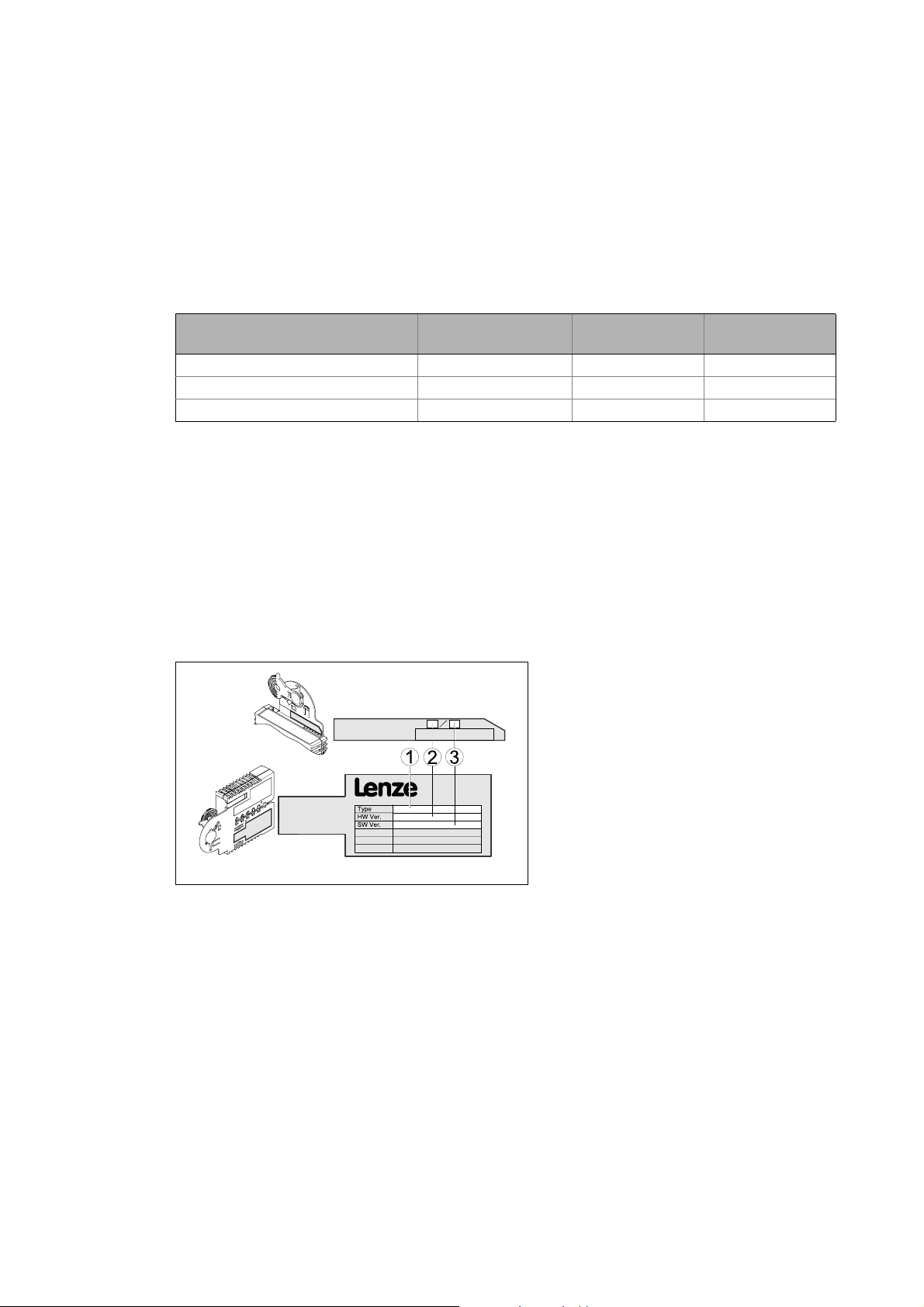
3.2 Identification
The type designation as well as the hardware and software version of the communication module
are indicated on the nameplate:
[3-1] Nameplate
E94YCPM005
version
1 Type designation (type)
E94 Product series
AVersion
Y Module identification: extension module
C Module type: communication module
PM PROFIBUS
2 Hardware version (HW)
3 Software version (SW)
From software
version
12
Lenze · E94AYCPM communication module (PROFIBUS®) · Communication Manual · DMS 12.0 EN · 11/2012 · TD17
Page 13

3 Product description
3.3 Features
_ _ _ _ _ _ _ _ _ _ _ _ _ _ _ _ _ _ _ _ _ _ _ _ _ _ _ _ _ _ _ _ _ _ _ _ _ _ _ _ _ _ _ _ _ _ _ _ _ _ _ _ _ _ _ _ _ _ _ _ _ _ _ _
3.3 Features
• Interface module for the PROFIBUS communication system to be connected to the expansion
slots of the Servo Drives 9400
• Support of parameter data channels DRIVECOM (DP-V0) and PROFIDrive (DP-V1)
• Transfer of safe information via the PROFIsafe protocol if an SM301 safety module (E94AYAE) is
used simultaneously
• A maximum of 32 process data words per direction can be exchanged.
• The communication module can either be supplied internally by the Servo Drive 9400 or
externally by a separate voltage source.
• Bus coupling via remote bus according to the RS485 standard
• Automatic detection of the baud rate (9.6 kbps to 12 Mbps)
• Setting of the station address is possible via DIP switch or code.
• Software compatibility with the EMF2133IB communication module
• Access to all Lenze parameters
Lenze · E94AYCPM communication module (PROFIBUS®) · Communication Manual · DMS 12.0 EN · 11/2012 · TD17 13
Page 14
3 Product description
3.4 Terminals and interfaces
_ _ _ _ _ _ _ _ _ _ _ _ _ _ _ _ _ _ _ _ _ _ _ _ _ _ _ _ _ _ _ _ _ _ _ _ _ _ _ _ _ _ _ _ _ _ _ _ _ _ _ _ _ _ _ _ _ _ _ _ _ _ _ _
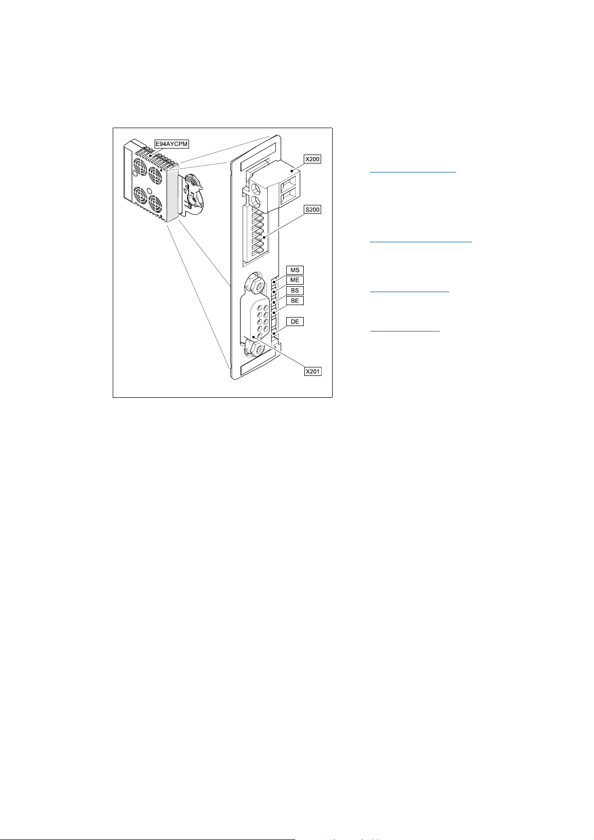
3.4 Terminals and interfaces
X200 2-pin plug connector with screw connection for
external voltage supply
External voltage supply
S200 DIP switches for setting the ...
• Station address
• compatibility with the EMF2133IB
communication module
Possible DIP switch settings
X201 PROFIBUS connection:
9-pin Sub-D socket
PROFIBUS connection
MS
5 LED status displays for diagnostic purposes
ME
LED status displays
BS
BE
DE
( 28)
( 31)
( 27)
( 82)
E94YCPM001A
[3-2] E94AYCPM communication module (PROFIBUS)
14
Lenze · E94AYCPM communication module (PROFIBUS®) · Communication Manual · DMS 12.0 EN · 11/2012 · TD17
Page 15

4Technical data
4.1 General data and operating conditions
_ _ _ _ _ _ _ _ _ _ _ _ _ _ _ _ _ _ _ _ _ _ _ _ _ _ _ _ _ _ _ _ _ _ _ _ _ _ _ _ _ _ _ _ _ _ _ _ _ _ _ _ _ _ _ _ _ _ _ _ _ _ _ _
4 Technical data
"Servo Drives 9400" Hardware Manual
Here you can find the ambient conditions and information on the electromagnetic
compatibility (EMC) which also apply to the communication module.
4.1 General data and operating conditions
Area Values
Order designation E94AYCPM
Communication profile • PROFIBUS DP-V0 (DRIVECOM)
• PROFIBUS DP-V1 (PROFIdrive)
Communication medium RS485
Interface 9-pin Sub-D socket
Network topology • Line (without repeater)
• Tree/line (with repeater)
Bus device type PROFIBUS slave
Number of slaves • Max. 31 (without repeater)
• Max. 125 (with repeater)
Max. cable length 1200 m (depending on the selected baud rate and the cable type used)
PNO identification number 0x07A8
Baud rate for cable type A (EN 50170) 9.6 kbps ... 12 Mbps (automatic detection)
Voltage supply External supply via the 2-pin plug connector
• Terminal "+": U = 24 V DC (20.4 V - 0 % ... 28.8 V + 0 %), I = 130 mA
• Terminal "-": Reference potential for external voltage supply
Conformities, approvals • CE
•UL
Lenze · E94AYCPM communication module (PROFIBUS®) · Communication Manual · DMS 12.0 EN · 11/2012 · TD17 15
Page 16

4Technical data
4.2 Protective insulation
_ _ _ _ _ _ _ _ _ _ _ _ _ _ _ _ _ _ _ _ _ _ _ _ _ _ _ _ _ _ _ _ _ _ _ _ _ _ _ _ _ _ _ _ _ _ _ _ _ _ _ _ _ _ _ _ _ _ _ _ _ _ _ _
4.2 Protective insulation
Danger!
Dangerous voltage
If the Servo Drives 9400 are operated on a phase earthed mains with a rated mains
voltage ≥ 400 V, external measures need to be implemented in order to ensure
protection against accidental contact.
Possible consequences:
Death or severe injury
Protective measures:
If protection against accidental contact is required for the control terminals of the
controller and the terminals of the plugged-in device modules, ...
• a double isolating distance must be provided.
• the components to be connected must be provided with a second isolating distance.
Note!
The existing protective insulation in the Servo Drives 9400 is implemented according to
EN 61800-5-1.
16
Lenze · E94AYCPM communication module (PROFIBUS®) · Communication Manual · DMS 12.0 EN · 11/2012 · TD17
Page 17
4Technical data
4.2 Protective insulation
_ _ _ _ _ _ _ _ _ _ _ _ _ _ _ _ _ _ _ _ _ _ _ _ _ _ _ _ _ _ _ _ _ _ _ _ _ _ _ _ _ _ _ _ _ _ _ _ _ _ _ _ _ _ _ _ _ _ _ _ _ _ _ _
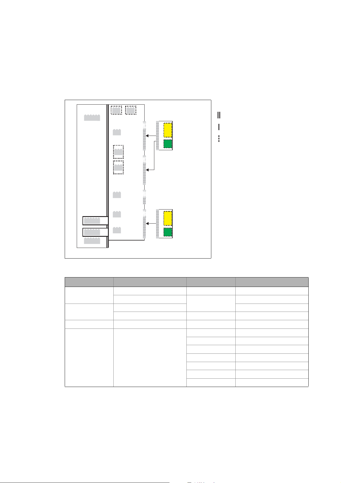
The following illustration ...
• shows the arrangement of the terminal strips and the separate potential areas of the Servo
Drive 9400.
• serves to determine the decisive protective insulation between two terminals located in
differently insulated separate potential areas.
X2
X100
X1
X3
X4
X5
MXI1
Bus
Ext. DC
MXI2
Reinforced insulation
Basic insulation
Functional insulation
X6X6
X7X7
MMI
MSI
X107
X106
X8X8
X105X105
[4-1] Protective insulation in accordance with EN61800-5-1
Terminal strip Connection Terminal strip Connection
X100 L1, L2, L3 (Single Drive only) X1 CAN on board 9400
+UG, -UG X2 State bus
X105 U, V, W 24 V (ext.)
Rb1, Rb2 (Single Drive only) X3 Analog inputs/outputs
X106 Motor PTC X4 Digital outputs
X107 Control of the motor holding
brake
I/O
Ext. DC
E94YCXX007
X5 Digital inputs
X6 Diagnostics
X7 Resolver
X8 Encoder
MXI1, MXI2 Extension module
MMI Memory module
MSI Safety module
Lenze · E94AYCPM communication module (PROFIBUS®) · Communication Manual · DMS 12.0 EN · 11/2012 · TD17 17
Page 18

4Technical data
4.2 Protective insulation
_ _ _ _ _ _ _ _ _ _ _ _ _ _ _ _ _ _ _ _ _ _ _ _ _ _ _ _ _ _ _ _ _ _ _ _ _ _ _ _ _ _ _ _ _ _ _ _ _ _ _ _ _ _ _ _ _ _ _ _ _ _ _ _
Example
Which type of protective insulation is used between the bus terminal of the device module in slot
MXI1 or MXI2 and the mains terminal X100?
The separate potential area with the better protective insulation is decisive.
• The separate potential area of the device module's bus terminal is "functionally insulated".
• The separate potential area of the mains terminal has a "reinforced insulation".
Result: The insulation between the mains terminal X100 and the bus terminal is of the "reinforced
insulation" type.
18
Lenze · E94AYCPM communication module (PROFIBUS®) · Communication Manual · DMS 12.0 EN · 11/2012 · TD17
Page 19

4Technical data
4.3 Protocol data
_ _ _ _ _ _ _ _ _ _ _ _ _ _ _ _ _ _ _ _ _ _ _ _ _ _ _ _ _ _ _ _ _ _ _ _ _ _ _ _ _ _ _ _ _ _ _ _ _ _ _ _ _ _ _ _ _ _ _ _ _ _ _ _
4.3 Protocol data
Area Values
Process data words (PCD) 1 ... 32 words (16 bits/word)
Cyclic parameter data channel (DPV0)
Acyclic parameter data channel (DPV1)
Safety data 4 words
PROFIBUS user data length 1 ... 32 words (process data)
4.4 Communication time
The communication time is the time between the start of a request and the arrival of the
corresponding response.
4 words
Max. 240 bytes
+ 4 words (parameter data or safety data)
The communication times in a PROFIBUS network depend on ...
• the processing time in the controller;
• the transmission delay time (baud rate / telegram length);
• the nesting depth of the network.
Processing time in the controller
Data Processing time
Process data Approx. 4 ms
+ 0 ... 1 ms
+ 1 ... x ms
Parameter data Approx. 30 ms + 20 ms tolerance (typical)
For some codes, the processing time may be longer (see software manual/
online help for the Servo Drive 9400).
update cycle
processing time in the module
application task runtime of the technology application used
(tolerance)
There are no interdependencies between parameter data and process data.
Lenze · E94AYCPM communication module (PROFIBUS®) · Communication Manual · DMS 12.0 EN · 11/2012 · TD17 19
Page 20
4Technical data
4.5 Dimensions
_ _ _ _ _ _ _ _ _ _ _ _ _ _ _ _ _ _ _ _ _ _ _ _ _ _ _ _ _ _ _ _ _ _ _ _ _ _ _ _ _ _ _ _ _ _ _ _ _ _ _ _ _ _ _ _ _ _ _ _ _ _ _ _
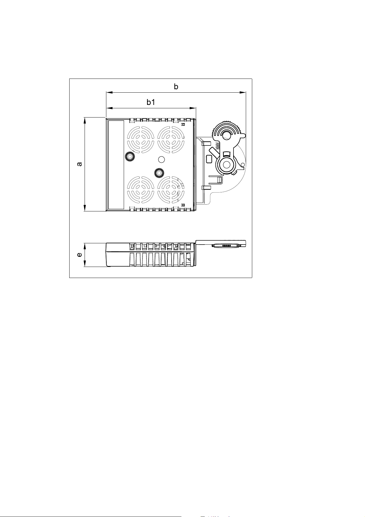
4.5 Dimensions
a 89 mm
b 134 mm
b1 87 mm
e 23 mm
E94YCXX005
[4-2] Dimensions
20
Lenze · E94AYCPM communication module (PROFIBUS®) · Communication Manual · DMS 12.0 EN · 11/2012 · TD17
Page 21

5 Installation
_ _ _ _ _ _ _ _ _ _ _ _ _ _ _ _ _ _ _ _ _ _ _ _ _ _ _ _ _ _ _ _ _ _ _ _ _ _ _ _ _ _ _ _ _ _ _ _ _ _ _ _ _ _ _ _ _ _ _ _ _ _ _ _
5 Installation
Stop!
Electrostatic discharge
Electronic components within the communication module can be damaged or destroyed
by electrostatic discharge.
Possible consequences:
• The communication module is defective.
• Communication via the fieldbus is not possible or faulty.
Protective measures
Discharge electrostatic charges before touching the module.
Lenze · E94AYCPM communication module (PROFIBUS®) · Communication Manual · DMS 12.0 EN · 11/2012 · TD17 21
Page 22
5 Installation
5.1 Mechanical installation
_ _ _ _ _ _ _ _ _ _ _ _ _ _ _ _ _ _ _ _ _ _ _ _ _ _ _ _ _ _ _ _ _ _ _ _ _ _ _ _ _ _ _ _ _ _ _ _ _ _ _ _ _ _ _ _ _ _ _ _ _ _ _ _
5.1 Mechanical installation
Note!
A safety bus system (PROFIsafe) can only be operated via the upper module slot (MXI1)
of the Servo Drive 9400.
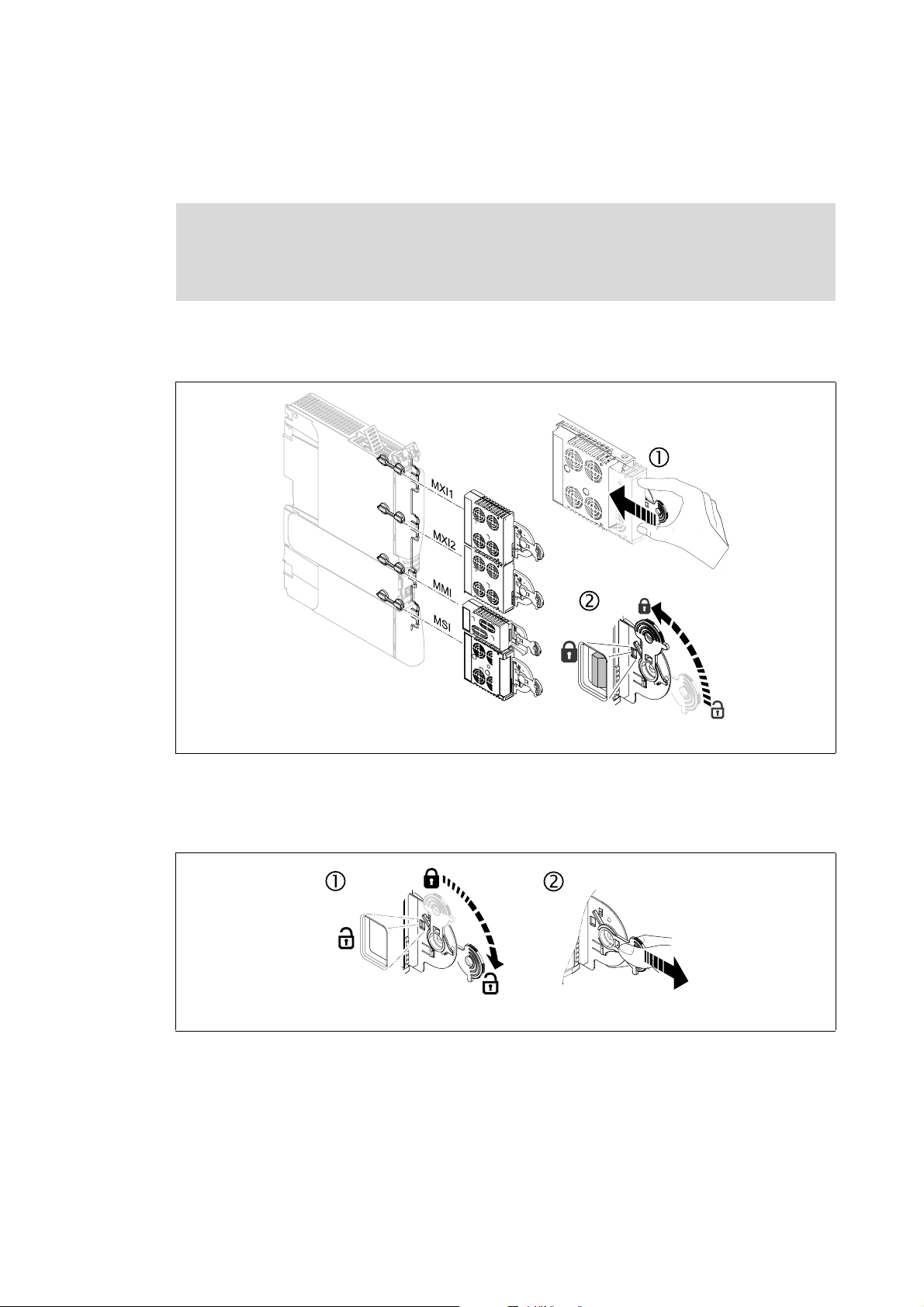
5.1.1 Mounting
[5-1] Mounting
5.1.2 Dismounting
[5-2] Dismounting
E94YCXX001G
E94AYCXX001H
22
Lenze · E94AYCPM communication module (PROFIBUS®) · Communication Manual · DMS 12.0 EN · 11/2012 · TD17
Page 23
5 Installation
5.2 Electrical installation
_ _ _ _ _ _ _ _ _ _ _ _ _ _ _ _ _ _ _ _ _ _ _ _ _ _ _ _ _ _ _ _ _ _ _ _ _ _ _ _ _ _ _ _ _ _ _ _ _ _ _ _ _ _ _ _ _ _ _ _ _ _ _ _
5.2 Electrical installation
Documentation for the standard device, control system, plant/machine
Observe the notes and wiring instructions given in the documentation.
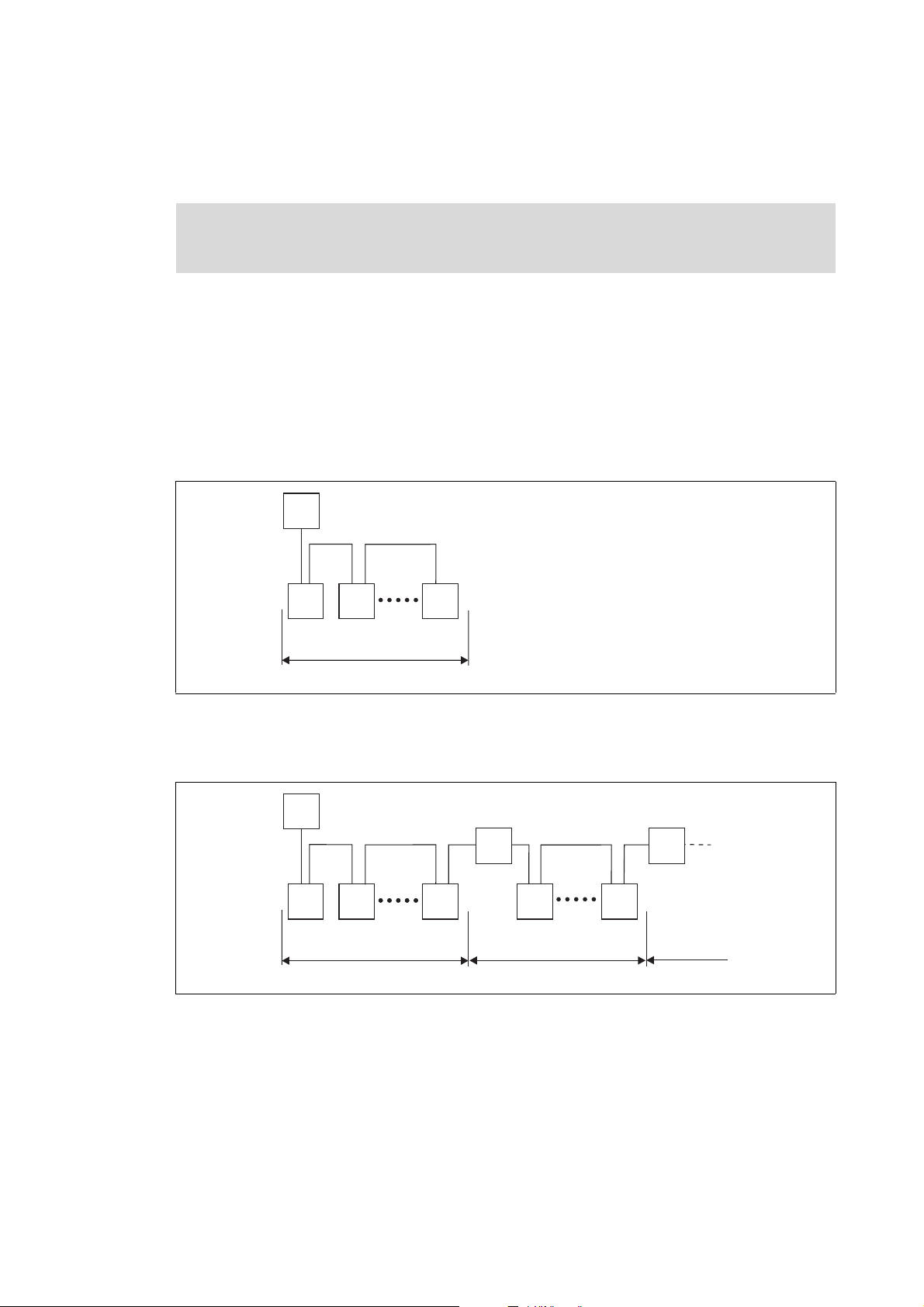
5.2.1 Network topology
The following examples show two simple RS485 networks.
Every segment of the network must be terminated at both ends. The bus terminators of the
PROFIBUS are marked with a "Z" in the below examples.
In the case of an RS485 network of only one segment, the PROFIBUS master (M) with the integrated
bus terminator starts the segment while the bus terminating resistor in the connector of the last
PROFIBUS station (S) must be activated.
M
Z
Z
S SS
1
[5-3] RS485 network with one segment
An RS485 network consisting of several segments contains repeaters (R) for connecting the
segments. The repeaters are provided with integrated bus terminating resistors.
M
Z
Z
Z
S SS
Z
R
S S
Z
R
Z
1 23
[5-4] RS485 network with a repeater
E94YCPM012a
E94YCPM012b
If no repeater is to be used at the end of the segment, the bus terminating resistor must be activated
in the connector of the last device. The bus termination is supplied by the station itself.
Lenze · E94AYCPM communication module (PROFIBUS®) · Communication Manual · DMS 12.0 EN · 11/2012 · TD17 23
Page 24
5 Installation
5.2 Electrical installation
_ _ _ _ _ _ _ _ _ _ _ _ _ _ _ _ _ _ _ _ _ _ _ _ _ _ _ _ _ _ _ _ _ _ _ _ _ _ _ _ _ _ _ _ _ _ _ _ _ _ _ _ _ _ _ _ _ _ _ _ _ _ _ _
If the communication module is supplied externally, the bus terminator can be supplied
independently of the standard device supply.
External voltage supply
( 28)
Note!
The bus terminator must always be supplied. Otherwise, the bus can get unstable.
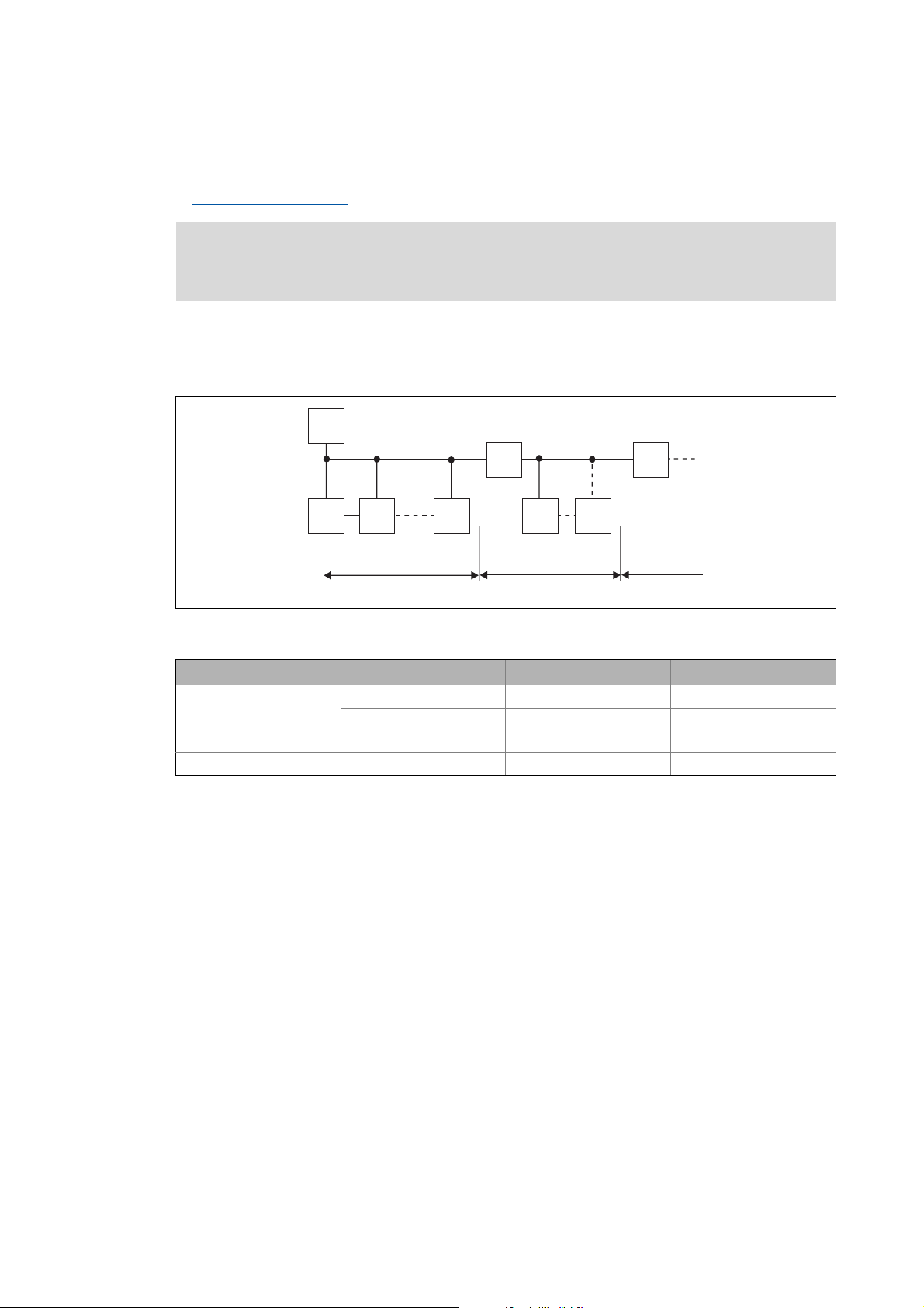
Activating the bus terminating resistor
Number of stations
( 25)
M
RR
SS S S S
123
2133PFB004
[5-5] Number of stations
Segment Master (M) Slave (S) Repeater (R)
1131-
230-
2-301
3-301
24
Tip!
Repeaters do not have a station address. When calculating the maximum number of
stations, they reduce the number of stations by 1 on each side of the segment.
Repeaters can be used to build up line and tree topologies. The maximum total bus system
expansion depends on ...
• the baud rate used;
• the number of repeaters used.
Lenze · E94AYCPM communication module (PROFIBUS®) · Communication Manual · DMS 12.0 EN · 11/2012 · TD17
Page 25

5 Installation
5.2 Electrical installation
_ _ _ _ _ _ _ _ _ _ _ _ _ _ _ _ _ _ _ _ _ _ _ _ _ _ _ _ _ _ _ _ _ _ _ _ _ _ _ _ _ _ _ _ _ _ _ _ _ _ _ _ _ _ _ _ _ _ _ _ _ _ _ _
5.2.2 Activating the bus terminating resistor
The PROFIBUS must be terminated by a bus terminating resistor at the first and last physical bus
station.
The bus terminating resistor in the bus connector of the bus cable is activated by means of a switch.
PROFIBUS cables with integrated bus terminating resistor are offered by several cable
manufacturers.
Note!
If you want to disconnect individual bus stations, ensure that the bus terminators at the
cable ends remain active.
Please observe that the bus termination is not active any longer if ...
• the bus connector has been disconnected;
• the voltage supply of the Servo Drive 9400 has been switched off;
•the External voltage supply
off.
( 28) of the communication module has been switched
Lenze · E94AYCPM communication module (PROFIBUS®) · Communication Manual · DMS 12.0 EN · 11/2012 · TD17 25
Page 26

5 Installation
5.2 Electrical installation
_ _ _ _ _ _ _ _ _ _ _ _ _ _ _ _ _ _ _ _ _ _ _ _ _ _ _ _ _ _ _ _ _ _ _ _ _ _ _ _ _ _ _ _ _ _ _ _ _ _ _ _ _ _ _ _ _ _ _ _ _ _ _ _
5.2.3 Bus cable specification
Note!
Only use cables which meet the listed specifications of the PROFIBUS user organisation.
Area Values
Cable resistance 135 ... 165 Ω/km, (f = 3 ... 20 MHz)
Capacitance per unit length ≤ 30 nF/km
Loop resistance < 110 Ω/km
Core diameter > 0.64 mm
Core cross-section > 0.34 mm
Cores Twisted in pairs, insulated and shielded
2
Bus cable length
The length of the bus cable depends on the baud rate and cable type used. The data in the following
table applies to PROFIBUS cables of "FC-Standard Cable" cable type .
Baud rate Length
9.6 ... 93.75 kbps 1200 m
187.5 kbps 1000 m
500 kbps 400 m
1500 kbps 200 m
3000 ... 12000 kbps 100 m
Note!
The baud rate depending of the data volume, cycle time and number of stations should
only be selected as high as required for the application.
Tip!
We recommend taking the use of optical fibres into consideration for high baud rates.
Advantages of optical fibres:
• External electromagnetic interferences have no effect on the transmission path.
• Bus lengths of several kilometres are also possible with higher baud rates.
• The bus length is ...
• independent of the baud rate;
• dependent on the optical fibre used.
26
Lenze · E94AYCPM communication module (PROFIBUS®) · Communication Manual · DMS 12.0 EN · 11/2012 · TD17
Page 27
5 Installation
5.2 Electrical installation
_ _ _ _ _ _ _ _ _ _ _ _ _ _ _ _ _ _ _ _ _ _ _ _ _ _ _ _ _ _ _ _ _ _ _ _ _ _ _ _ _ _ _ _ _ _ _ _ _ _ _ _ _ _ _ _ _ _ _ _ _ _ _ _
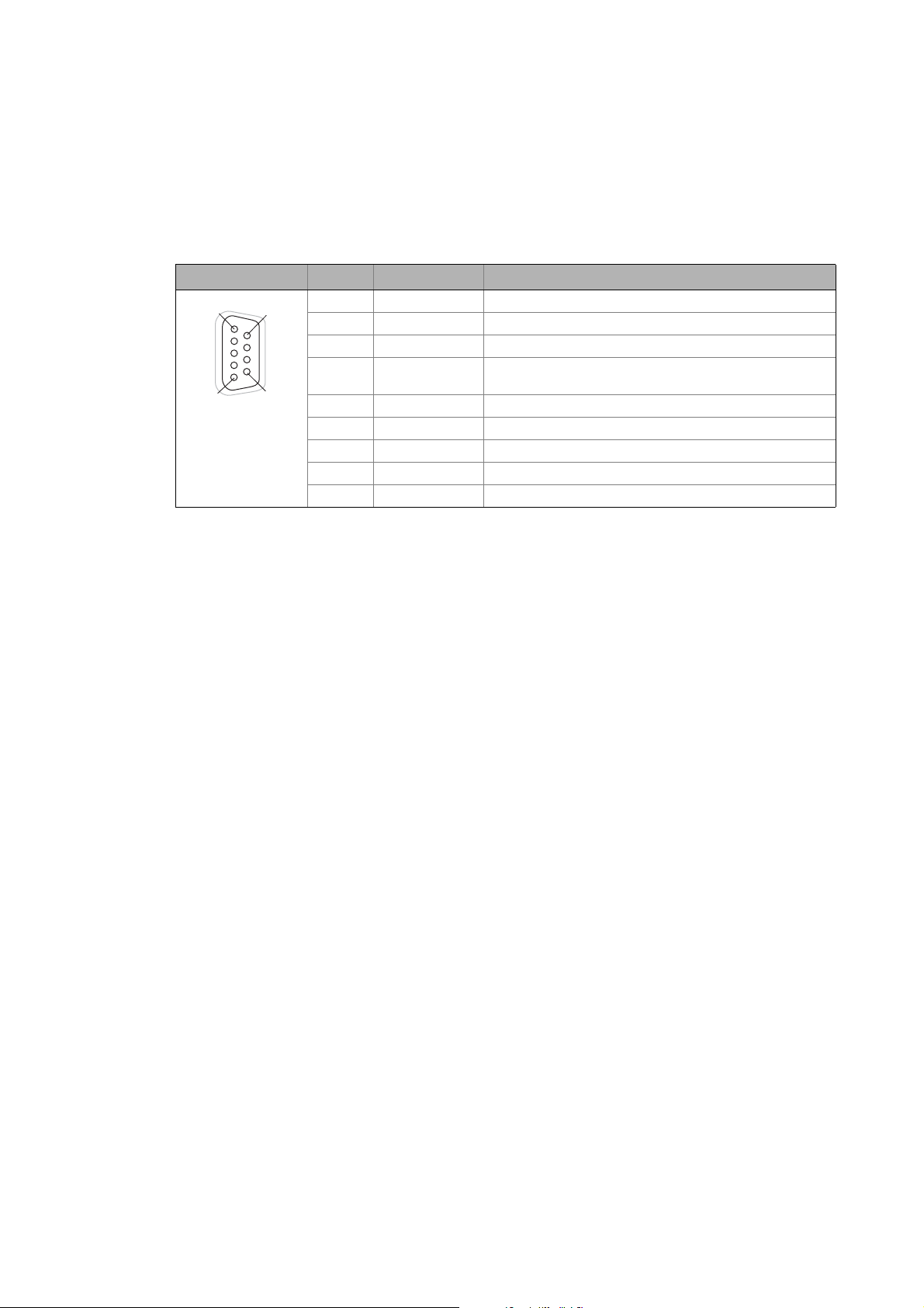
5.2.4 PROFIBUS connection
The 9-pin Sub-D socket X201 serves to connect the communication module to the bus system.
Assignment of the 9-pin Sub-D socket X201
View Pin Assignment Description
1
5
6
9
1Not assigned-
2Not assigned-
3 RxD/TxD-P Data line B (received data/transmitted data, plus)
4 RTS Request To Send (received data/transmitted data, no
differential signal)
5 M5V2 Data ground (ground to 5 V)
6 P5V2 5 V DC / 30 mA (bus termination)
7Not assigned-
8 RxD/TxD-N Data line A (received data/transmitted data, minus)
9Not assigned-
Lenze · E94AYCPM communication module (PROFIBUS®) · Communication Manual · DMS 12.0 EN · 11/2012 · TD17 27
Page 28
5 Installation
5.2 Electrical installation
_ _ _ _ _ _ _ _ _ _ _ _ _ _ _ _ _ _ _ _ _ _ _ _ _ _ _ _ _ _ _ _ _ _ _ _ _ _ _ _ _ _ _ _ _ _ _ _ _ _ _ _ _ _ _ _ _ _ _ _ _ _ _ _
5.2.5 External voltage supply
Note!
With external voltage supply, always use a separate power supply unit, safely separated
to EN 61800-5-1 in every control cabinet (SELV / PELV).
External voltage supply of the communication module is necessary if the bus communication is to
continue when the supply of the standard device fails.
It is not possible to access the parameters of a standard device disconnected from the mains.
If required, feed the communication module with a separate supply voltage via the 2-pin plug
connector.
Assignment of the 2-pin plug connector (X200)
Designation Explanation
+ V = 24 V DC (20.4 V - 0 % ... 28.8 V + 0 %)
I = 130 mA
- Reference potential for external voltage supply
Terminal data
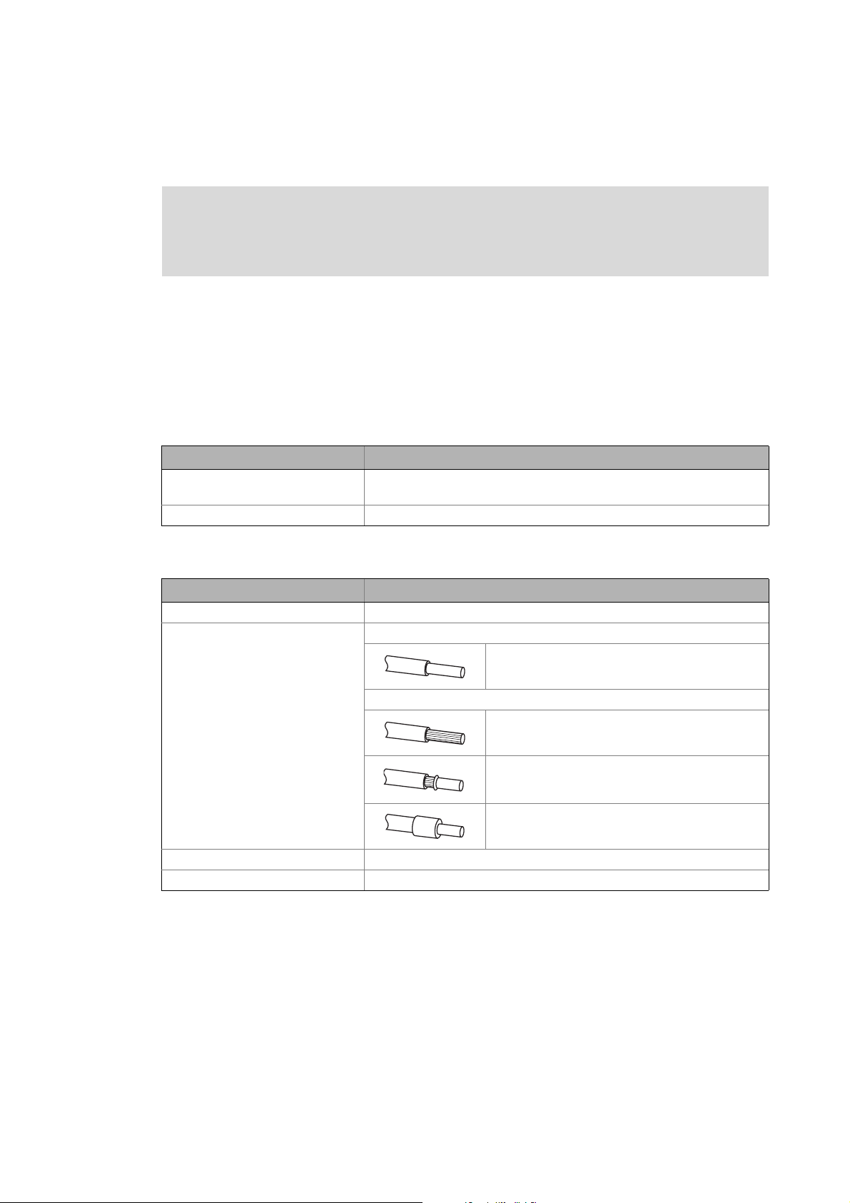
Area Values
Electrical connection Plug connector with screw connection
Possible connections Rigid:
0.2 ... 1.5 mm
Flexible:
Without wire end ferrule
0.2 ... 1.5 mm
With wire end ferrule, without plastic sleeve
0.2 ... 1.5 mm
With wire end ferrule, with plastic sleeve
0.2 ... 1.5 mm
Tightening torque 0.5 ... 0.6 Nm (4.4 ... 5.3 lb-in)
Stripping length 6 mm
2
(AWG 24 ... 16)
2
(AWG 24 ... 16)
2
(AWG 24 ... 16)
2
(AWG 24 ... 16)
28
Lenze · E94AYCPM communication module (PROFIBUS®) · Communication Manual · DMS 12.0 EN · 11/2012 · TD17
Page 29

6 Commissioning
6.1 Before initial switch-on
_ _ _ _ _ _ _ _ _ _ _ _ _ _ _ _ _ _ _ _ _ _ _ _ _ _ _ _ _ _ _ _ _ _ _ _ _ _ _ _ _ _ _ _ _ _ _ _ _ _ _ _ _ _ _ _ _ _ _ _ _ _ _ _
6 Commissioning
During commissioning, plant-specific data such as motor parameters, operating parameters,
responses, and parameters for fieldbus communication are defined for the controller. Lenze devices
use codes for this purpose.
The codes of the controller and for communication are saved to the memory module in a nonvolatile data set.
In addition, there are codes for diagnosing and monitoring the stations.
Note!
When parameterising the communication module, please observe that the code number
depends on the slot of the Servo Drive 9400 in which the communication module has
been inserted.
The first two digits of the code number indicate the slot:
•C13nnn for slot MXI1
Parameters of the communication module for slot MXI1
•C14nnn for slot MXI2
Parameters of the communication module for slot MXI2
You also have to set the Communication-relevant parameters of the standard device
( 91)
.
( 93)
( 102)
6.1 Before initial switch-on
Stop!
Before switching on the controller for the first time, check ...
• the entire wiring for completeness, short circuit and earth fault:
• whether the bus system is terminated through a bus terminating resistor at the first
and last physical bus station.
Activating the bus terminating resistor
( 25)
Lenze · E94AYCPM communication module (PROFIBUS®) · Communication Manual · DMS 12.0 EN · 11/2012 · TD17 29
Page 30

6 Commissioning
6.2 Configuration of the host (master)
_ _ _ _ _ _ _ _ _ _ _ _ _ _ _ _ _ _ _ _ _ _ _ _ _ _ _ _ _ _ _ _ _ _ _ _ _ _ _ _ _ _ _ _ _ _ _ _ _ _ _ _ _ _ _ _ _ _ _ _ _ _ _ _
6.2 Configuration of the host (master)
The host (master) must be configured before communication with the communication module is
possible.
Configuration for the host system (master) and the DP-V0 parameter data channel
For configuring the PROFIBUS you must read the device description file of the communication
module into the master.
The device description file for the E94AYCPM communication module (PROFIBUS) can be found in
the download area at:
www.Lenze.com
The following language variants of the device description file can be used:
• LENZ07A8.GSD (source file, English)
• LENZ07A8.GSG (German)
• LENZ07A8.GSE (English)
Defining the user data length
The user data length is defined during the initialisation phase of the master.
The Servo Drives 9400 support the configuration of a maximum of 32 process data words (max.
64 bytes). The optional activation of the cyclic parameter data channel additionally occupies
4 process data words (8 bytes). The transfer of PROFIsafe messages, too, occupies 4 additional
process data words.
The user data lengths for process input data and process output data are the same.
Description of the device data base file
Selection text Parameter data
DRIVECOM-PAR
(cons) + PCD (nW
cons)
PCD (nW cons) - n words -n words
PCD (nW) - -4 words 4 words
Safety (4W) - 4 words -4 words
n = 1 ... 32 process data words
with consistency
Process data Assigned
with consistency without consistency
Yes n words -4 + n words
IO memory
30
Example of selecting the device data base file
DRIVECOM-PAR (cons) + PCD (8W cons)
• "Drivecom-PAR (cons)" = DP-V0 parameter data channel (4 words)
• "PCD (8W cons)" = 8 process data words
Tip!
A detailed description of consistency is given in the chapter "Consistent parameter data
( 76).
Lenze · E94AYCPM communication module (PROFIBUS®) · Communication Manual · DMS 12.0 EN · 11/2012 · TD17
"
Page 31

6 Commissioning
6.3 Possible DIP switch settings
_ _ _ _ _ _ _ _ _ _ _ _ _ _ _ _ _ _ _ _ _ _ _ _ _ _ _ _ _ _ _ _ _ _ _ _ _ _ _ _ _ _ _ _ _ _ _ _ _ _ _ _ _ _ _ _ _ _ _ _ _ _ _ _
6.3 Possible DIP switch settings
The front-panel DIP switches can be used to set:
• The station address (switches 1 ... 64)
• Compatibility with the communication module EMF2133IB
(switch 2133)
Lenze setting: all switches in OFF position
E94YCPM001D
[6-1] DIP switch
6.3.1 Setting the station address
The station addresses must differ from each other if several networked PROFIBUS stations are used.
The station address can be set via the DIP switches 1 ... 64 or via the »Engineer« (code C13899
C14899
Condition At least one switch 1…64=ON •Switches 1...64=OFF
The housing labelling indicates the valencies of the individual DIP switches for setting the station
address.
DIP switch 64 32 16 8 4 2 1
Switch position OFF OFF ON OFF ON ON ON
Value 00
Station address = sum of the valencies = 16 + 4 + 2 + 1 = 23
).
Setting the station address via ...
DIP switch C13899 / 14899
•Switch 1 ... 64 = ON
(invalid value "127")
16 0 4 2 1
DIP switch positions for setting the station address ( 116)
• Valid address range: 1 … 126 (max. 126 slave stations)
• C13920
• C13864
/ C14920: Display of the current address setting of the switches
/ C14864: Display of the station address active on the PROFIBUS
/
Note!
Switch off the voltage supply of the communication module and then on again in order
to activate changed settings.
Lenze · E94AYCPM communication module (PROFIBUS®) · Communication Manual · DMS 12.0 EN · 11/2012 · TD17 31
Page 32

6 Commissioning
6.3 Possible DIP switch settings
_ _ _ _ _ _ _ _ _ _ _ _ _ _ _ _ _ _ _ _ _ _ _ _ _ _ _ _ _ _ _ _ _ _ _ _ _ _ _ _ _ _ _ _ _ _ _ _ _ _ _ _ _ _ _ _ _ _ _ _ _ _ _ _
Setting the station address via the »Engineer«
In the »Engineer«, the station address can be set via the Settings tab.
Invalid addresses are displayed in red in the Station address input field (code C13899
Save the changed settings via the device command C00002 = 11 (save start parameters).
6.3.2 Establishing EMF2133IB compatibility
Establishing EMF2133IB compatibility is necessary if you need to communicate with systems using
an EMF2133IB PROFIBUS communication module.
Software compatibility can be set via DIP switch 2133.
Switch Switch position Function
2133 ON Establishing EMF2133IB compatibility
Note!
• In the compatibility mode "EMF2133IB", only the DRIVECOM parameter data channel
(DP-V0) and the Lenze device control can be used.
• Switch off the voltage supply of the communication module and then on again in
order to activate changed settings.
/ C14899).
OFF No EMF2133IB compatibility
32
Communication manual for the EMF2133IB module
Here you can find information on the configuration of the EMF2133IB communication
module and the identification of the module on the bus.
Lenze · E94AYCPM communication module (PROFIBUS®) · Communication Manual · DMS 12.0 EN · 11/2012 · TD17
Page 33

6 Commissioning
6.4 First switch-on
_ _ _ _ _ _ _ _ _ _ _ _ _ _ _ _ _ _ _ _ _ _ _ _ _ _ _ _ _ _ _ _ _ _ _ _ _ _ _ _ _ _ _ _ _ _ _ _ _ _ _ _ _ _ _ _ _ _ _ _ _ _ _ _
6.4 First switch-on
Documentation for the standard device
Observe the safety instructions and residual hazards stated.
Note!
Establishing communication
In order to establish communication via an externally supplied communication module,
the standard device must be switched on as well.
After communication has been established, the externally supplied module operates
independently of the power on/off state of the standard device.
Protection against uncontrolled restart
After a fault (e.g. short-time mains failure), the restart of a drive is not always wanted
and - in some cases - even not allowed.
In the Lenze setting of the Servo Drives 9400, the restart protection is activated.
Via C00142 ("Auto-restart after mains connection"), you can configure the restart
behaviour of the controller:
C00142 = "0: Inhibited" (Lenze setting)
• The controller remains inhibited (even if the fault is no longer active).
• The drive starts in a controlled mode by explicitly enabling the controller: LOW-HIGH
edge at digital input X5/RFR.
C00142 = "1: Enabled"
• An uncontrolled restart of the drive is possible.
Lenze · E94AYCPM communication module (PROFIBUS®) · Communication Manual · DMS 12.0 EN · 11/2012 · TD17 33
Page 34

6 Commissioning
6.5 Going online with »Engineer« via TCI
_ _ _ _ _ _ _ _ _ _ _ _ _ _ _ _ _ _ _ _ _ _ _ _ _ _ _ _ _ _ _ _ _ _ _ _ _ _ _ _ _ _ _ _ _ _ _ _ _ _ _ _ _ _ _ _ _ _ _ _ _ _ _ _
6.5 Going online with »Engineer« via TCI
Via Tool Calling Interfaces (TCI) you can connect to a TCI-capable integrated development
environment and parameterise and diagnose your field devices without having to exit the
integrated development environment.
You cannot set the TCI communication path directly in the »Engineer«. The selection is carried out
by the »STEP7« Siemens software.
The TCI function requires a PN/DP-CPU. Information on the Siemens PLC types that are equipped
with the TCI function is provided via the Siemens Support at:
http://support.automation.siemens.com
How to configure TCI communication:
1. Alllocate names for the individual axes in the »Engineer« project.
In our case, "9400" was allocated for 9400 HighLine, and "8400" for 8400 StateLine:
34
Lenze · E94AYCPM communication module (PROFIBUS®) · Communication Manual · DMS 12.0 EN · 11/2012 · TD17
Page 35

6 Commissioning
6.5 Going online with »Engineer« via TCI
_ _ _ _ _ _ _ _ _ _ _ _ _ _ _ _ _ _ _ _ _ _ _ _ _ _ _ _ _ _ _ _ _ _ _ _ _ _ _ _ _ _ _ _ _ _ _ _ _ _ _ _ _ _ _ _ _ _ _ _ _ _ _ _
2. In »STEP7« in the »HW Config« ...
• create the Lenze PROFIBUS stations with the corresponding station addresses and
•create a PROFIBUS network.
Here a Servo Drive 9400 (address 3) and an Inverter Drive 8400 (address 4) are operated on
the PROFIBUS.
• The names of the PROFIBUS slaves in the »HW Config« must be identical to those of the
corresponding Lenze axes in the »Engineer« (here "9400" and "8400").
• The selection of the process data configuration has no impact on TCI communication.
3. Establish an Ethernet connection to the PROFIBUS CPU.
Lenze · E94AYCPM communication module (PROFIBUS®) · Communication Manual · DMS 12.0 EN · 11/2012 · TD17 35
Page 36

6 Commissioning
6.5 Going online with »Engineer« via TCI
_ _ _ _ _ _ _ _ _ _ _ _ _ _ _ _ _ _ _ _ _ _ _ _ _ _ _ _ _ _ _ _ _ _ _ _ _ _ _ _ _ _ _ _ _ _ _ _ _ _ _ _ _ _ _ _ _ _ _ _ _ _ _ _
4. Load the »STEP7« project to the CPU.
5. Use the menu command Insert Station 7PG/PC to integrate a PG/PC station into the
»STEP7« project.
6. By double-clicking the PG/PC station inserted, open its "Properties" dialog.
7. Under the Interfaces tab, select a new Ethernet interface and confirm with OK.
36
Lenze · E94AYCPM communication module (PROFIBUS®) · Communication Manual · DMS 12.0 EN · 11/2012 · TD17
Page 37

6 Commissioning
6.5 Going online with »Engineer« via TCI
_ _ _ _ _ _ _ _ _ _ _ _ _ _ _ _ _ _ _ _ _ _ _ _ _ _ _ _ _ _ _ _ _ _ _ _ _ _ _ _ _ _ _ _ _ _ _ _ _ _ _ _ _ _ _ _ _ _ _ _ _ _ _ _
8. Select the connection which you are using to go online with »STEP7« (the same Ethernet
connection that has been configured in the »HW Config«).
In our case this is the Ethernet(1) connection:
9. Confirm the selection with OK.
The connection has been accepted.
Lenze · E94AYCPM communication module (PROFIBUS®) · Communication Manual · DMS 12.0 EN · 11/2012 · TD17 37
Page 38

6 Commissioning
6.5 Going online with »Engineer« via TCI
_ _ _ _ _ _ _ _ _ _ _ _ _ _ _ _ _ _ _ _ _ _ _ _ _ _ _ _ _ _ _ _ _ _ _ _ _ _ _ _ _ _ _ _ _ _ _ _ _ _ _ _ _ _ _ _ _ _ _ _ _ _ _ _
10. Select the actual PG/PC connection under the Assignment tab.
The connection highlighted is assigned by means of the Assign button.
11. Confirm the following message with OK.
38
Lenze · E94AYCPM communication module (PROFIBUS®) · Communication Manual · DMS 12.0 EN · 11/2012 · TD17
Page 39

6 Commissioning
6.5 Going online with »Engineer« via TCI
_ _ _ _ _ _ _ _ _ _ _ _ _ _ _ _ _ _ _ _ _ _ _ _ _ _ _ _ _ _ _ _ _ _ _ _ _ _ _ _ _ _ _ _ _ _ _ _ _ _ _ _ _ _ _ _ _ _ _ _ _ _ _ _
12. After the assignment, the connection appears in the "Assigned" display area. Complete the
dialog with OK.
13. In the »STEP7« project, the PG/PC station is marked with a yellow arrow. (The connection
selected is active.)
Lenze · E94AYCPM communication module (PROFIBUS®) · Communication Manual · DMS 12.0 EN · 11/2012 · TD17 39
Page 40

6 Commissioning
6.5 Going online with »Engineer« via TCI
_ _ _ _ _ _ _ _ _ _ _ _ _ _ _ _ _ _ _ _ _ _ _ _ _ _ _ _ _ _ _ _ _ _ _ _ _ _ _ _ _ _ _ _ _ _ _ _ _ _ _ _ _ _ _ _ _ _ _ _ _ _ _ _
14. Start the transfer of the TCI communication parameters in the »HW Config« using the right
mouse button and the menu command Start device tool L-force Engineer.
15. If the »Engineer« has already been started with the applicable project, the following
message will appear:
• The message says that the »Engineer« project is not set to a TCI communication path and
provides information on whether this action is to be executed now.
• If you confirm the message with Yes, the applicable TCI communication parameter
settings of the »STEP7« project are transferred to the »Engineer«.
40
Lenze · E94AYCPM communication module (PROFIBUS®) · Communication Manual · DMS 12.0 EN · 11/2012 · TD17
Page 41

6 Commissioning
6.5 Going online with »Engineer« via TCI
_ _ _ _ _ _ _ _ _ _ _ _ _ _ _ _ _ _ _ _ _ _ _ _ _ _ _ _ _ _ _ _ _ _ _ _ _ _ _ _ _ _ _ _ _ _ _ _ _ _ _ _ _ _ _ _ _ _ _ _ _ _ _ _
If the »Engineer« has not already been started, it is started automatically now and you have
to open the applicable project.
If the project selected has not been set to a TCI communication path yet, this can now be
executed with Yes:
16. The transfer of the TCI communication parameters is documented in the »Engineer«
message window.
Here the communication settings have been carried out successfully. The individual
PROFIBUS addresses in the respective codes have been adapted to the »STEP7« project.
Lenze · E94AYCPM communication module (PROFIBUS®) · Communication Manual · DMS 12.0 EN · 11/2012 · TD17 41
Page 42

6 Commissioning
6.5 Going online with »Engineer« via TCI
_ _ _ _ _ _ _ _ _ _ _ _ _ _ _ _ _ _ _ _ _ _ _ _ _ _ _ _ _ _ _ _ _ _ _ _ _ _ _ _ _ _ _ _ _ _ _ _ _ _ _ _ _ _ _ _ _ _ _ _ _ _ _ _
17. If you now call the "Go online" function of the »Engineer«, the TCI communication settings
are displayed as follows:
• "STEP7 Communication Server" appears as bus connection.
• The device access path contains a very long string.
•Use the Connect button to establish an online connection.
•By means of the Search/Enter button, you can update the TCI communication
parameters.
42
Lenze · E94AYCPM communication module (PROFIBUS®) · Communication Manual · DMS 12.0 EN · 11/2012 · TD17
Page 43

7 Data transfer
_ _ _ _ _ _ _ _ _ _ _ _ _ _ _ _ _ _ _ _ _ _ _ _ _ _ _ _ _ _ _ _ _ _ _ _ _ _ _ _ _ _ _ _ _ _ _ _ _ _ _ _ _ _ _ _ _ _ _ _ _ _ _ _
7 Data transfer
The PROFIBUS master and controller communicate through the exchange of data telegrams via
PROFIBUS. The user data area of the data telegram contains parameter data or process data. In the
controller, different communication channels are assigned to the parameter data and process data.
Communication channels
The process data channel serves to transfer process data.
• The process data serve to control the drive controller.
• The host (master) can directly access the process data. In the PLC, for instance, the data are
directly saved to the I/O area.
• Process data are not saved in the controller.
• Process data are transferred cyclically between the host system and the controllers (permanent
exchange of current input / output data).
• Process data are, for instance, setpoints, actual values, control words and status words.
• The Servo Drives 9400 can exchange a maximum of 32 process data words (16 bits/word) per
direction.
Note!
Observe the direction of the information flow!
Process input data (Rx data):
• Process data from the controller (slave) to the master
Process output data (Tx data):
• Process data from the master to the controller (slave)
The parameter data channel serves to transfer parameter data.
• The parameter data channel provides access to all Lenze codes.
• In general, the parameter data transfer is not time-critical.
• Parameter data are, for instance, operating parameters, diagnostic information, and motor
data.
• Parameter data changes must be saved via code C00002 of the Servo Drives 9400.
Lenze · E94AYCPM communication module (PROFIBUS®) · Communication Manual · DMS 12.0 EN · 11/2012 · TD17 43
Page 44

8 Process data transfer
_ _ _ _ _ _ _ _ _ _ _ _ _ _ _ _ _ _ _ _ _ _ _ _ _ _ _ _ _ _ _ _ _ _ _ _ _ _ _ _ _ _ _ _ _ _ _ _ _ _ _ _ _ _ _ _ _ _ _ _ _ _ _ _
8 Process data transfer
PDO mapping
The Servo Drives 9400 HighLine enable the individual mapping of process data. For this purpose, the
»Engineer« is provided with a port configurator.
Below you can find a description of the steps required to implement a process data communication
with a higher-level control, in which a control word/status word and a 32-bit setpoint/actual value
are exchanged.
Note!
The »Engineer« screenshots shown on the following pages are only examples for the
setting sequence and the resulting screens.
PDO mapping with the »Engineer«
1. You can carry out the mapping of the process data in the »Engineer« on the Process data
objects tab of the respective fieldbus communication module:
2. Select the receive object PDO_RX0:
44 Lenze · E94AYCPM communication module (PROFIBUS®) · Communication Manual · DMS 12.0 EN · 11/2012 · TD17
Page 45

8 Process data transfer
_ _ _ _ _ _ _ _ _ _ _ _ _ _ _ _ _ _ _ _ _ _ _ _ _ _ _ _ _ _ _ _ _ _ _ _ _ _ _ _ _ _ _ _ _ _ _ _ _ _ _ _ _ _ _ _ _ _ _ _ _ _ _ _
3. Click the Edit PDO button. The Process data object structure:PDO_RX0 selection window
opens:
Here you can map the individual ports from the Port selection list into the receive PDO
"PDO_RX0" by clicking the >> button. With the Up and Down buttons, you can change the
order of the ports within the PDO.
Note
The port mapping is not a configuration, which can be carried out online for the Servo
Drive 9400 HighLine. For this purpose, the »Engineer« project must be updated and then
the application must be downloaded.
In the following example, the ports "LPortControl1" and "Lport32In1" have been mapped
into the receive PDO "PDO_RX0" and the ports "LPortStatus1" and "LPort32Out1" have been
mapped into the transmit PDO "PDO_TX0":
Lenze · E94AYCPM communication module (PROFIBUS®) · Communication Manual · DMS 12.0 EN · 11/2012 · TD17 45
Page 46

8 Process data transfer
_ _ _ _ _ _ _ _ _ _ _ _ _ _ _ _ _ _ _ _ _ _ _ _ _ _ _ _ _ _ _ _ _ _ _ _ _ _ _ _ _ _ _ _ _ _ _ _ _ _ _ _ _ _ _ _ _ _ _ _ _ _ _ _
4. Now link the mapped ports to the application signals in the selected technology
application.
• If the »FB Editor« is not activated, you can use the multiplexer codes (from code C03000
onwards) for this purpose.
• If the »FB Editor« is activated, the multiplexer codes are no longer available. In this case,
you have to do the linking directly in the »FB Editor«.
46 Lenze · E94AYCPM communication module (PROFIBUS®) · Communication Manual · DMS 12.0 EN · 11/2012 · TD17
Page 47

9 Parameter data transfer
9.1 Addressing of the parameter data
_ _ _ _ _ _ _ _ _ _ _ _ _ _ _ _ _ _ _ _ _ _ _ _ _ _ _ _ _ _ _ _ _ _ _ _ _ _ _ _ _ _ _ _ _ _ _ _ _ _ _ _ _ _ _ _ _ _ _ _ _ _ _ _
9 Parameter data transfer
The E94AYCPM communication module supports the cyclic and acyclic transmission of parameter
data:
• Cyclic DP-V0 parameter data are based on the DRIVECOM profile.
If the parameter data channel is active according to DP-V0, it is assigned an additional 4 words
of input / output data.
• Acyclic DP-V1 parameter data are based on the PROFIdrive profile.
9.1 Addressing of the parameter data
The parameter data are addressed via codes which can be found in this documentation and in the
corresponding documentation of your controller.
Parameter reference
Addressing of Lenze parameters
In the case of the DP-V0 parameter data channel, the parameters of a device are not addressed
directly via Lenze code numbers, but via indices (bytes 3 + 4) and subindices (byte 2).
The conversion is made via an offset (24575 / 0x5FFF):
•PROFIBUS-DP index
•PROFIBUS-DP index
Example of C00105 (quick stop deceleration time):
•PROFIBUS-DP index
•PROFIBUS-DP index
The parameter values are entered into the user data (bytes 5 to 8) of the telegram.
( 91)
= 24575 - Lenze code number
dec
= 0x5FFF - Lenze code number
hex
= 24575 - 105 = 24470
dec
= 0x5FFF - 0x69 = 0x5F96
hex
hex
Lenze · E94AYCPM communication module (PROFIBUS®) · Communication Manual · DMS 12.0 EN · 11/2012 · TD17 47
Page 48

9 Parameter data transfer
9.2 DRIVECOM parameter data channel (DP-V0)
_ _ _ _ _ _ _ _ _ _ _ _ _ _ _ _ _ _ _ _ _ _ _ _ _ _ _ _ _ _ _ _ _ _ _ _ _ _ _ _ _ _ _ _ _ _ _ _ _ _ _ _ _ _ _ _ _ _ _ _ _ _ _ _
9.2 DRIVECOM parameter data channel (DP-V0)
The DRIVECOM parameter data channel (DP-V0) ...
• enables parameter setting and diagnosing of the controller;
• provides access to all Lenze parameters (codes);
• additionally occupies 4 words (16 bits/word) of the input and output data words in the master;
• is identical for both transmission directions.
9.2.1 Telegram structure (overview)
The telegram of the parameter data channel consists of a total of 8 bytes:
Byte 1 Byte 2 Byte 3 Byte 4 Byte 5 Byte 6 Byte 7 Byte 8
Service Subindex Index
High byte
Index
Low byte
Data 4 /
Error 4
Data 3 /
Error 3
Data 2 /
Error 2
Data 1 /
Error 1
The individual bytes are described in detail in the following subchapters.
48
Lenze · E94AYCPM communication module (PROFIBUS®) · Communication Manual · DMS 12.0 EN · 11/2012 · TD17
Page 49

9 Parameter data transfer
9.2 DRIVECOM parameter data channel (DP-V0)
_ _ _ _ _ _ _ _ _ _ _ _ _ _ _ _ _ _ _ _ _ _ _ _ _ _ _ _ _ _ _ _ _ _ _ _ _ _ _ _ _ _ _ _ _ _ _ _ _ _ _ _ _ _ _ _ _ _ _ _ _ _ _ _
9.2.2 Byte 1: Service
Byte 1 Byte 2 Byte 3 Byte 4 Byte 5 Byte 6 Byte 7 Byte 8
Service Subindex Index
High byte
Request and response control for the parameter data channel
[9-1] Method of reading for bits 0 ... 7
Bit 0 ... 2: Request
Read/write request from the master to the controller
000 No request
001 Read request
Reading parameter data from the controller
010 Write request (write data to the controller)
Writing parameter data to the controller
100 Data transfer abort by the master
Data transfer abort by the master
Index
Low byte
76543210
( 51)
Data 4 /
Error 4
( 50)
( 50)
Data 3 /
Error 3
Data 2 /
Error 2
Data 1 /
Error 1
Bit 3
Reserved
Bit 4/5: Data length
Data length ≤ 4 bytes in the telegram bytes 5 ... 8 (data 1 ... 4 / error 1 ... 4)
00 1 byte
01 2 bytes
10 3 bytes
11 4 bytes
Bit 6: Handshake
Indicates a new request.
• The state of this (toggle) bit is changed by the master for every new request.
• The controller copies the bit into its response telegram.
Bit 7: Status
Status information from the controller to the master when sending the request confirmation.
This status bit informs the master whether the request has been carried out without errors.
0 Request completed without errors.
Bytes 5 ... 8 contain a parameter value (Data 1 ... 4 ).
1 Request not completed because of an error.
• The set status bit indicates that the telegram is an "error telegram".
• Bytes 5 ... 8 contain an error code (Error 1 ... 4 ).
Error codes
( 54)
Lenze · E94AYCPM communication module (PROFIBUS®) · Communication Manual · DMS 12.0 EN · 11/2012 · TD17 49
Page 50

9 Parameter data transfer
9.2 DRIVECOM parameter data channel (DP-V0)
_ _ _ _ _ _ _ _ _ _ _ _ _ _ _ _ _ _ _ _ _ _ _ _ _ _ _ _ _ _ _ _ _ _ _ _ _ _ _ _ _ _ _ _ _ _ _ _ _ _ _ _ _ _ _ _ _ _ _ _ _ _ _ _
9.2.2.1 Reading parameter data from the controller
General procedure:
1. Define the user data area of the controller, i.e. define the location of the DP user data in the host
(observe manufacturer-specific information).
2. Enter the address of the required parameter in the "Index" and "Subindex" fields (DP output
data).
3. Request in the service byte = read request.
The handshake bit in the service byte must be changed (DP output data).
4. Check whether the handshake bit in the service byte is the same for the DP input data and the
DP output data.
• If the handshake bit is the same, the response has been received.
• It is useful to implement a time monitoring tool.
5. Check whether the status bit in the service byte is set:
• Status bit isnot
( 53)
.
• Status bit is set: The read request has not
contains the Error codes
set: The "Data/Error" field contains the required Parameter value (data)
been executed correctly. The "Data/Error" field
( 54).
9.2.2.2 Writing parameter data to the controller
General procedure:
1. Define the user data area of the controller, i.e. define the location of the DP user data in the host
(observe manufacturer-specific information).
2. Enter the address of the required parameter in the "Index" and "Subindex" fields (DP output
data).
3. Enter the parameter value in the "Data/Error" field.
4. Request in the service byte = write request.
The handshake bit in the service byte must be changed (DP output data).
5. Check whether the handshake bit in the service byte is the same for the DP input data and the
DP output data.
• If the handshake bit is the same, the response has been received.
• It is useful to implement a time monitoring tool.
6. Check whether the status bit in the service byte is set:
• Status bit is not
• Status bit is set: The write request has not
contains the Error codes
set: The write request has been executed correctly.
( 54).
been executed correctly. The "Data/Error" field
50
Lenze · E94AYCPM communication module (PROFIBUS®) · Communication Manual · DMS 12.0 EN · 11/2012 · TD17
Page 51

9 Parameter data transfer
9.2 DRIVECOM parameter data channel (DP-V0)
_ _ _ _ _ _ _ _ _ _ _ _ _ _ _ _ _ _ _ _ _ _ _ _ _ _ _ _ _ _ _ _ _ _ _ _ _ _ _ _ _ _ _ _ _ _ _ _ _ _ _ _ _ _ _ _ _ _ _ _ _ _ _ _
9.2.2.3 Abort of data transfer by the controller
The error telegram is used to abort the transfer.
• The error telegram is marked by a set status bit in the service byte.
• The telegram can either be the response to an "Initiate Read/Write Service" or to a "Read/Write
Segment Service".
Controller response in the event of an error:
Byte 1 Byte 2 Byte 3 Byte 4 Byte 5 Byte 6 Byte 7 Byte 8
Service Subindex Index
High byte
1t110000 SIDX IDXH IDXL Error Class Error code Additional
9.2.2.4 Data transfer abort by the master
Index
Low byte
Data 4 /
Error 4
Data 3 /
Error 3
Data 2 /
Error 2
Code High
Data 1 /
Error 1
Additional
Code Low
The master can use this error telegram to abort a running segment transmission.
• The error telegram is marked by a set status bit in the service byte.
• The service byte also contains the request code "4" (100
bin
).
• Bit 4 and bit 5 in the service byte (data length) are without meaning.
• Additional information (subindex, index, error information) is not transmitted.
Byte 1 Byte 2 Byte 3 Byte 4 Byte 5 Byte 6 Byte 7 Byte 8
Service Reserved Reserved Reserved Reserved Reserved Reserved Reserved
1txx0100 0 0 0 0000
Controller response in the case of correct execution:
The controller confirms the error telegram of the master by also sending an error telegram.
• The error telegram is marked by a set status bit in the service byte.
• In the case of correct execution, the telegram contains the error information "0x00000000" in
bytes 5 ... 8.
• Additional information (subindex, index) is not transmitted.
Byte 1 Byte 2 Byte 3 Byte 4 Byte 5 Byte 6 Byte 7 Byte 8
Service SIDX IDXH IDXL Error Class Error code Additional
Code High
1t110000 0 0 0 0000
Additional
Code Low
Lenze · E94AYCPM communication module (PROFIBUS®) · Communication Manual · DMS 12.0 EN · 11/2012 · TD17 51
Page 52

9 Parameter data transfer
9.2 DRIVECOM parameter data channel (DP-V0)
_ _ _ _ _ _ _ _ _ _ _ _ _ _ _ _ _ _ _ _ _ _ _ _ _ _ _ _ _ _ _ _ _ _ _ _ _ _ _ _ _ _ _ _ _ _ _ _ _ _ _ _ _ _ _ _ _ _ _ _ _ _ _ _
9.2.3 Byte 2: Subindex
Byte 1 Byte 2 Byte 3 Byte 4 Byte 5 Byte 6 Byte 7 Byte 8
Service Subindex Index
High byte
Additional addressing via the subindex is required for those codes of the Servo Drives 9400 that
contain a subcode (see code table).
9.2.4 Bytes 3 + 4: Index
Byte 1 Byte 2 Byte 3 Byte 4 Byte 5 Byte 6 Byte 7 Byte 8
Service Subindex Index
High byte
The parameter (Lenze code) is selected via these two bytes according to the formula:
Index = 24575 - Lenze code number
(See also "Addressing of Lenze parameters
Index
Low byte
Index
Low byte
" ( 47))
Data 4 /
Error 4
Data 4 /
Error 4
Data 3 /
Error 3
Data 3 /
Error 3
Data 2 /
Error 2
Data 2 /
Error 2
Data 1 /
Error 1
Data 1 /
Error 1
Example:
The parameter C00105 (quick stop (QSP) deceleration time) is to be addressed:
• Index = 24575 - 105 = 24470 = 0x5F96
• The entries in bytes 3 + 4 for this example would be:
Byte 1 Byte 2 Byte 3 Byte 4 Byte 5 Byte 6 Byte 7 Byte 8
Service Subindex 0x5F 0x96 Data 4 /
Error 4
Data 3 /
Error 3
Data 2 /
Error 2
Data 1 /
Error 1
52
Lenze · E94AYCPM communication module (PROFIBUS®) · Communication Manual · DMS 12.0 EN · 11/2012 · TD17
Page 53

9 Parameter data transfer
9.2 DRIVECOM parameter data channel (DP-V0)
_ _ _ _ _ _ _ _ _ _ _ _ _ _ _ _ _ _ _ _ _ _ _ _ _ _ _ _ _ _ _ _ _ _ _ _ _ _ _ _ _ _ _ _ _ _ _ _ _ _ _ _ _ _ _ _ _ _ _ _ _ _ _ _
9.2.5 Bytes 5 ... 8: Parameter value / error information
Byte 1 Byte 2 Byte 3 Byte 4 Byte 5 Byte 6 Byte 7 Byte 8
Service Subindex Index
High byte
The state of status bit 7 in the service byte determines the meaning of this data field:
Status bit Meaning of bytes 5 ... 8
0 Bytes 5 ... 8 contain a parameter value (Data 1 ... 4 ).
1 Bytes 5 ... 8 contain an error code (Error 1 ... 4).
Error codes
( 54)
Parameter value (data)
Index
Low byte
Data 4 /
Error 4
Data 3 /
Error 3
Data 2 /
Error 2
Data 1 /
Error 1
Note!
Strings or data blocks cannot be transmitted.
Depending on the data format, the length of the parameter value is between 1 and 4 bytes.
Data are saved in the Motorola format, i.e. first the high byte (high word), then the low byte (low
word):
Byte 5 Byte 6 Byte 7 Byte 8
High byte Low byte High byte Low byte
High word Low word
Double word
Principle for the assignment of bytes 5 ... 8 with parameter values of different lengths:
Byte 5 Byte 6 Byte 7 Byte 8
Parameter value (length 1) 0x00 0x00 0x00
Parameter value (length 2) 0x00 0x00
Parameter value (length 4)
Lenze · E94AYCPM communication module (PROFIBUS®) · Communication Manual · DMS 12.0 EN · 11/2012 · TD17 53
Page 54

9 Parameter data transfer
9.2 DRIVECOM parameter data channel (DP-V0)
_ _ _ _ _ _ _ _ _ _ _ _ _ _ _ _ _ _ _ _ _ _ _ _ _ _ _ _ _ _ _ _ _ _ _ _ _ _ _ _ _ _ _ _ _ _ _ _ _ _ _ _ _ _ _ _ _ _ _ _ _ _ _ _
9.2.6 Error codes
The following error messages may appear:
Byte 8 Byte 7 Byte 6 Byte 5 Meaning
Error 1 Error 2 Error 3 Error 4
0x06 0x03 0x00 0x00 No right to access
0x06 0x05 0x11 Invalid subindex
0x06 0x05 0x12 Data length too large
0x06 0x05 0x13 Data length too small
0x06 0x07 0x00 Object does not exist
0x06 0x08 0x00 Data types do not comply with each other
0x08 0x00 0x00 Request cannot be executed
0x08 0x00 0x20 Request cannot be executed at the moment
0x08 0x00 0x22 Request cannot be executed due to the device status / The
0x08 0x00 0x30 Value ranged exited
0x08 0x00 0x31 Parameter value too high
0x08 0x00 0x32 Parameter value too low
0x08 0x00 0x80 Hardware error
parameter can only be changed in the case of a controller inhibit
54
Lenze · E94AYCPM communication module (PROFIBUS®) · Communication Manual · DMS 12.0 EN · 11/2012 · TD17
Page 55

9 Parameter data transfer
9.2 DRIVECOM parameter data channel (DP-V0)
_ _ _ _ _ _ _ _ _ _ _ _ _ _ _ _ _ _ _ _ _ _ _ _ _ _ _ _ _ _ _ _ _ _ _ _ _ _ _ _ _ _ _ _ _ _ _ _ _ _ _ _ _ _ _ _ _ _ _ _ _ _ _ _
9.2.7 Telegram examples
9.2.7.1 Read request: Querying the heatsink temperature
The heatsink temperature of the controller is to be read.
• Code to be read: C00061
• Heatsink temperature: 43 °C
Byte 1: Service (request)
Request = 0t110001
• Bit 0 ... 2 = 001
• Bit 3 = 0 (reserved)
• Bit 4/5 = 01
• Bit 6 = handshake bit (t ≡ status is changed in the response telegram)
bin
for read request
bin
for 2-byte data length (only relevant for the response telegram)
bin
• Bit 7 = status bit (only relevant for the response telegram)
Byte 2: Subindex
Subindex = 0 because code C00061 does not contain any subindices.
Bytes 3+4: Index
Index = 24575 - code number = 24575 - 61 = 24514 = 0x5FC2
• Byte 3 (high byte) = 0x5F
• Byte 4 (low byte) = 0xC2
Bytes 5 ... 8: Data
The response telegram contains the value of code C00061:
Data 3 + 4 = 43 [°C] x 1 (internal factor) = 43 = 0x002B
Result
Request telegram from master to drive:
Byte 1 Byte 2 Byte 3 Byte 4 Byte 5 Byte 6 Byte 7 Byte 8
Service Subindex Index
High byte
0x01 0x00 0x5F 0xC2 0x00 0x00 0x00 0x00
0t000001
Waiting for change of handshake bit 6 in service byte 1 of the response.
bin
00000000
bin
01011111
bin
Index
Low byte
11000010
Data 4 Data 3 Data 2 Data 1
bin
00000000
bin
00000000
bin
00000000
bin
00000000
bin
Response telegram from drive to master (for correct execution):
Byte 1 Byte 2 Byte 3 Byte 4 Byte 5 Byte 6 Byte 7 Byte 8
Service Subindex Index
High byte
0x11 0x00 0x5F 0xC2 0x00 0x2B 0x00 0x00
0t010001
Lenze · E94AYCPM communication module (PROFIBUS®) · Communication Manual · DMS 12.0 EN · 11/2012 · TD17 55
bin
00000000
bin
01011111
bin
Index
Low byte
11000010
Data 4 Data 3 Data 2 Data 1
bin
00000000
bin
00101011
bin
00000000
bin
00000000
bin
Page 56

9 Parameter data transfer
9.2 DRIVECOM parameter data channel (DP-V0)
_ _ _ _ _ _ _ _ _ _ _ _ _ _ _ _ _ _ _ _ _ _ _ _ _ _ _ _ _ _ _ _ _ _ _ _ _ _ _ _ _ _ _ _ _ _ _ _ _ _ _ _ _ _ _ _ _ _ _ _ _ _ _ _
9.2.7.2 Write request: Setting the deceleration time for quick stop (QSP)
In the controller, the deceleration time for quick stop (QSP) is to be set to 50 ms.
• Code to be written: C00105
Byte 1: Service (request)
Request = 0t110010
• Bit 0 ... 2 = 010
• Bit 3 = 0 (reserved)
• Bit 4/5 = 11
• Bit 6 = handshake bit (t ≡ status is changed in the response telegram)
• Bit 7 = status bit (only relevant for the response telegram)
Byte 2: Subindex
Subindex = 0 because code C00105 does not contain any subindices.
bin
for write request
bin
for 4-byte data length
bin
Bytes 3+4: Index
Index = 24575 - code number = 24575 - 105 = 24470 = 0x5F96
• Byte 3 (high byte) = 0x5F
• Byte 4 (low byte) = 0x96
Bytes 5 ... 8: Data
The parameter value of 0.05 s to be set is multiplied by the code-specific factor of "1000" and
entered in the user data:
Data 1 ... 4 = 0.05 [s] x 1000 (internal factor) = 50 = 0x00000032
Result:
Request telegram from master to drive:
Byte 1 Byte 2 Byte 3 Byte 4 Byte 5 Byte 6 Byte 7 Byte 8
Service Subindex Index
High byte
0x72 0x00 0x5F 0x96 0x00 0x00 0x00 0x32
0t110010
Waiting for change of handshake bit 6 in service byte 1 of the response
bin
00000000
bin
01011111
bin
Index
Low byte
10010110
Data 4 Data 3 Data 2 Data 1
bin
00000000
bin
00000000
bin
00000000
bin
00110010
bin
Response telegram from drive to master (for correct execution):
56
Byte 1 Byte 2 Byte 3 Byte 4 Byte 5 Byte 6 Byte 7 Byte 8
Service Subindex Index
High byte
0x40 0x00 0x5F 0x96 0x00 0x00 0x00 0x32
0t000000
bin
00000000
01011111
bin
Lenze · E94AYCPM communication module (PROFIBUS®) · Communication Manual · DMS 12.0 EN · 11/2012 · TD17
bin
Index
Low byte
10010110
Data 4 Data 3 Data 2 Data 1
bin
00000000
bin
00000000
bin
00000000
bin
00110010
bin
Page 57

9 Parameter data transfer
9.3 PROFIdrive parameter data channel (DP-V1)
_ _ _ _ _ _ _ _ _ _ _ _ _ _ _ _ _ _ _ _ _ _ _ _ _ _ _ _ _ _ _ _ _ _ _ _ _ _ _ _ _ _ _ _ _ _ _ _ _ _ _ _ _ _ _ _ _ _ _ _ _ _ _ _
9.3 PROFIdrive parameter data channel (DP-V1)
Data communication with PROFIBUS-DP-V0 is characterised by cyclic diagnostics and cyclic process
data and parameter data transfer.
An optional service expansion is the acyclic parameter data transfer of PROFIBUS-DP-V1. This
service does not impair the functionality of the standard services under PROFIBUS-DP-V0.
PROFIBUS-DP-V0 and PROFIBUS-DP-V1 can be operated simultaneously in the same network. This
enables the step-by-step expansion or retrofitting of a system.
The services of PROFIBUS-DP-V1 can be used by the class 1 master (PLC) and the class 2 master
(diagnostics master, etc.).
The integration of the acyclic service into the fixed bus cycle depends on the corresponding
configuration of the class 1 master:
• With configuration, a time slot is reserved.
• Without configuration the acyclic service is appended when a class 2 master acyclically accesses
a DP-V1 slave.
Features
• Parameter number and subindex addresses with a width of 16 bits each.
• Several parameter requests can be combined to one request (multi-parameter request).
• There is always only one parameter request in process (no pipelining).
• A parameter request/response must fit into a data block (max. 240 bytes). Requests/responses
cannot be split into several data blocks.
• No spontaneous messages are transferred.
• There are only acyclic parameter requests.
• Profile-specific parameters can be read independently of the slave state.
Lenze · E94AYCPM communication module (PROFIBUS®) · Communication Manual · DMS 12.0 EN · 11/2012 · TD17 57
Page 58

9 Parameter data transfer
9.3 PROFIdrive parameter data channel (DP-V1)
_ _ _ _ _ _ _ _ _ _ _ _ _ _ _ _ _ _ _ _ _ _ _ _ _ _ _ _ _ _ _ _ _ _ _ _ _ _ _ _ _ _ _ _ _ _ _ _ _ _ _ _ _ _ _ _ _ _ _ _ _ _ _ _
9.3.1 Connection establishment between master and slave
A class 1 master can always request parameters from a slave if the slave is in the "Data_Exchange"
state.
In addition to the class 1 master, a class 2 master can establish a communication connection to the
slave:
DPV1parameter data channel
Read
Slave
Write
[9-2] Data communication via the DP-V1 parameter data channel
Master
class 1
Master
class 2
E94YCPM010
58
Lenze · E94AYCPM communication module (PROFIBUS®) · Communication Manual · DMS 12.0 EN · 11/2012 · TD17
Page 59

9 Parameter data transfer
9.3 PROFIdrive parameter data channel (DP-V1)
_ _ _ _ _ _ _ _ _ _ _ _ _ _ _ _ _ _ _ _ _ _ _ _ _ _ _ _ _ _ _ _ _ _ _ _ _ _ _ _ _ _ _ _ _ _ _ _ _ _ _ _ _ _ _ _ _ _ _ _ _ _ _ _
9.3.2 Acyclic data transfer
Note!
A parameter request refers to one or several parameter(s) (multi-parameter request).
Parameter request
[9-3] Transmission directions
Explanation
• A "Write.req" is used to pass the data set (DB47) to the slave in the form of a parameter request.
• With "Write.res" the master receives the confirmation for the receipt of the message.
Master
DP-V1
Write.req
with data (parameter request)
Write.res
without data
Read.req
without data
Read.res (-)
without data
Read.req
without data
Read.res (+)Parameter response
with data (parameter response)
Slave
Parameter request
Parameter response
Parameter
processing
E94YCPM011
• The master requests the response of the slave with "Read.req".
• The slave responds with "Read.res (-)" if processing has not yet been completed.
• After parameter processing, the parameter request is completed by transmitting the parameter
response to the master with "Read.res (+)".
Lenze · E94AYCPM communication module (PROFIBUS®) · Communication Manual · DMS 12.0 EN · 11/2012 · TD17 59
Page 60

9 Parameter data transfer
9.3 PROFIdrive parameter data channel (DP-V1)
_ _ _ _ _ _ _ _ _ _ _ _ _ _ _ _ _ _ _ _ _ _ _ _ _ _ _ _ _ _ _ _ _ _ _ _ _ _ _ _ _ _ _ _ _ _ _ _ _ _ _ _ _ _ _ _ _ _ _ _ _ _ _ _
9.3.3 Telegram structure
SD LE LEr SD DA SA FCS EDFC DSAP SSAP
[9-4] PROFIBUS data telegram
The data unit (DU) contains the DP-V1 header and the parameter request or the parameter
response.
The following subchapters describe the parameter request and the parameter response in detail.
DU
E82ZAFP015
Note!
The DP-V1 header consists of:
• Function identification
•Slot number
• Data set
• Length of the user data
Please refer to the corresponding PROFIBUS specification for further information on the
DP-V1 header.
Assignment of the user data depending on the data type
Depending on the data type used, the user data are assigned as follows:
Data type Length User data assignment
Byte 1 Byte 2 Byte 3 Byte 4 Byte ...
String x bytes
U8 1 byte 0x00
U16 2 bytes
U32 4 bytes High word Low word
High byte Low byte
High byte Low byte High byte Low byte
60
Lenze · E94AYCPM communication module (PROFIBUS®) · Communication Manual · DMS 12.0 EN · 11/2012 · TD17
Page 61

9 Parameter data transfer
9.3 PROFIdrive parameter data channel (DP-V1)
_ _ _ _ _ _ _ _ _ _ _ _ _ _ _ _ _ _ _ _ _ _ _ _ _ _ _ _ _ _ _ _ _ _ _ _ _ _ _ _ _ _ _ _ _ _ _ _ _ _ _ _ _ _ _ _ _ _ _ _ _ _ _ _
9.3.3.1 Reading parameter data from the controller
Note!
• When a read request is processed, no parameter value is written to the slave.
• In the case of a multi-parameter read request, the parameter attribute, index, and
subindex are repeated with the number "n" of the requested parameters.
• A read request must not exceed the maximum data length of 240 bytes.
Request header
Byte 1 Byte 2 Byte 3 Byte 4
Request reference Request identification Axis Number of indices
Field Data type Values
Request reference U8 This value is specified by the master
Request identification U8 0x01: Request parameters for reading
Axis U8 0x00 or 0x01
Number of indices U8 0x"n" (n = number of parameters requested)
Parameter attribute
Byte 5 Byte 6
Attribute Number of subindices
Field Data type Values
Attribute U8 0x10: Value
Number of subindices U8 0x00
(For array elements: Enter the number of array elements
required.)
Index and subindex
Byte 7 Byte 8 Byte 9 Byte 10
Index Subindex
High byte Low byte High byte Low byte
Field Data type Values
Index U16 0x0001 ... 0xFFFF (1 ... 65535)
Subindex U16 0x0001 ... 0xFFFF (1 ... 65535)
Lenze · E94AYCPM communication module (PROFIBUS®) · Communication Manual · DMS 12.0 EN · 11/2012 · TD17 61
Page 62

9 Parameter data transfer
9.3 PROFIdrive parameter data channel (DP-V1)
_ _ _ _ _ _ _ _ _ _ _ _ _ _ _ _ _ _ _ _ _ _ _ _ _ _ _ _ _ _ _ _ _ _ _ _ _ _ _ _ _ _ _ _ _ _ _ _ _ _ _ _ _ _ _ _ _ _ _ _ _ _ _ _
9.3.3.2 Response to a correctly executed read request
Note!
Responses to a read request do not contain parameter attributes, indices and subindices.
Response header
Byte 1 Byte 2 Byte 3 Byte 4
Request reference
(mirrored)
Field Data type Values
Request reference U8 Mirrored value of the parameter request
Response identification U8 0x01: Parameter has been read
Axis U8 0x00 or 0x01
Number of indices U8 0x"n" (n = number of parameters requested)
Response identification Axis
(mirrored)
Number of indices
Parameter format
Byte 5 Byte 6
Format Number of values
Field Data type Values
Format U8 0x02: Integer8
0x03: Integer16
0x04: Integer32
0x05: Unsigned8
0x06: Unsigned16
0x07: Unsigned32
0x09: Visible string
0x0A: Octet string
0x40: Zero
0x41: Byte
0x42: Word
0x43: Double word
Number of values U8 0x01 or number of requested subindices/parameters
(with several subindices/parameters only the parameter
value is repeated).
In the case of string codes, the number of characters is
entered here.
62
Lenze · E94AYCPM communication module (PROFIBUS®) · Communication Manual · DMS 12.0 EN · 11/2012 · TD17
Page 63

9 Parameter data transfer
9.3 PROFIdrive parameter data channel (DP-V1)
_ _ _ _ _ _ _ _ _ _ _ _ _ _ _ _ _ _ _ _ _ _ _ _ _ _ _ _ _ _ _ _ _ _ _ _ _ _ _ _ _ _ _ _ _ _ _ _ _ _ _ _ _ _ _ _ _ _ _ _ _ _ _ _
Parameter value
Byte 7 Byte 8 Byte 9 Byte 10
Value
Field Data type Values
Value String Any (length > 4 bytes possible)
U8 0x00 .... 0xFF
U16 0x0000 .... 0xFFFF
U32 0x0000 0000 .... 0xFFFF FFFF
Lenze · E94AYCPM communication module (PROFIBUS®) · Communication Manual · DMS 12.0 EN · 11/2012 · TD17 63
Page 64

9 Parameter data transfer
9.3 PROFIdrive parameter data channel (DP-V1)
_ _ _ _ _ _ _ _ _ _ _ _ _ _ _ _ _ _ _ _ _ _ _ _ _ _ _ _ _ _ _ _ _ _ _ _ _ _ _ _ _ _ _ _ _ _ _ _ _ _ _ _ _ _ _ _ _ _ _ _ _ _ _ _
9.3.3.3 Response to a read error
Note!
In case of a multi-parameter request, correct and possibly faulty messages are
summarised in one telegram.
Correct message
• Format: data type of the value requested
• Number of values: as described in chapter "Reading parameter data from the
controller" ( 61).
• Parameter value: value requested
Faulty message
• Format: 0x44
• Number of values: 0x01 or 0x02
• Error code without additional information (for number of values = 0x01) or
• Error code with additional information (for number of values = 0x02)
A faulty access to a parameter "n" is indicated at the nth position in the response
telegram of a multi-parameter request.
Response header
Byte 1 Byte 2 Byte 3 Byte 4
Request reference
(mirrored)
Field Data type Values
Request reference U8 Mirrored value of the parameter request
Response identification U8 0x81: Parameter has not been read
Axis U8 0x00 or 0x01
Number of indices U8 0x"n" (n = number of parameters requested)
Parameter format
Byte 5 Byte 6
Format Number of values
Field Data type Values
Format U8 0x44: Error
Number of values U8 0x01: Error code without additional information
Response identification Axis
(mirrored)
The data in the bytes 7 + 8 must be interpreted as an
error code.
0x02: Error code with additional information
Number of indices
64
Lenze · E94AYCPM communication module (PROFIBUS®) · Communication Manual · DMS 12.0 EN · 11/2012 · TD17
Page 65

9 Parameter data transfer
9.3 PROFIdrive parameter data channel (DP-V1)
_ _ _ _ _ _ _ _ _ _ _ _ _ _ _ _ _ _ _ _ _ _ _ _ _ _ _ _ _ _ _ _ _ _ _ _ _ _ _ _ _ _ _ _ _ _ _ _ _ _ _ _ _ _ _ _ _ _ _ _ _ _ _ _
Error code
Byte 7 Byte 8 Byte 9 Byte 10
Error code Additional information
(if available)
High byte Low byte High byte Low byte
Field Data type Values
Error code U16 0x0000 .... 0xFFFF
Additional information
(if available)
U16
Error codes
( 70)
Lenze · E94AYCPM communication module (PROFIBUS®) · Communication Manual · DMS 12.0 EN · 11/2012 · TD17 65
Page 66

9 Parameter data transfer
9.3 PROFIdrive parameter data channel (DP-V1)
_ _ _ _ _ _ _ _ _ _ _ _ _ _ _ _ _ _ _ _ _ _ _ _ _ _ _ _ _ _ _ _ _ _ _ _ _ _ _ _ _ _ _ _ _ _ _ _ _ _ _ _ _ _ _ _ _ _ _ _ _ _ _ _
9.3.3.4 Writing parameter data to the controller
Note!
When a multi-parameter write request is transferred, the ...
• Parameter attribute
• Index and subindex
and then the ...
• Parameter format
• Parameter value
... are repeated with the number "n" of the parameters addressed.
A write request must not exceed the maximum data length of 240 bytes.
Request header
Byte 1 Byte 2 Byte 3 Byte 4
Request reference Request identification Axis Number of indices
Field Data type Values
Request reference U8 This value is defined by the master.
Request identification U8 0x02: Write parameter
Axis U8 0x00 or 0x01
Number of indices U8 0x"n" (n = number of parameters addressed)
Parameter attribute
Byte 5 Byte 6
Attribute Number of subindices
Field Data type Values
Attribute U8 0x10: Value
Number of subindices U8 0x00
(For array elements: Enter the number of array elements
required.)
Index and subindex
66
Byte 7 Byte 8 Byte 9 Byte 10
Index Subindex
High byte Low byte High byte Low byte
Field Data type Values
Index U16 0x0001 ... 0xFFFF (1 ... 65535)
Subindex U16 0x0001 ... 0xFFFF (1 ... 65535)
Lenze · E94AYCPM communication module (PROFIBUS®) · Communication Manual · DMS 12.0 EN · 11/2012 · TD17
Page 67

9 Parameter data transfer
9.3 PROFIdrive parameter data channel (DP-V1)
_ _ _ _ _ _ _ _ _ _ _ _ _ _ _ _ _ _ _ _ _ _ _ _ _ _ _ _ _ _ _ _ _ _ _ _ _ _ _ _ _ _ _ _ _ _ _ _ _ _ _ _ _ _ _ _ _ _ _ _ _ _ _ _
Parameter format
Byte 11 Byte 12
Format Number of values
Field Data type Values
Format U8 0x02: Integer8
0x03: Integer16
0x04: Integer32
0x05: Unsigned8
0x06: Unsigned16
0x07: Unsigned32
0x09: Visible string
0x0A: Octet string
0x40: Zero
0x41: Byte
0x42: Word
0x43: Double word
Number of values U8 0x01 or number of written subindices/parameters (with
several subindices/parameters only the parameter value
is repeated).
In the case of string codes, the number of characters is
entered here.
Parameter value
Byte 13 Byte 14 Byte 15 Byte 16
Value
Field Data type Values
Value String Any (length > 4 bytes possible)
U8 0x00 .... 0xFF
U16 0x0000 .... 0xFFFF
U32 0x0000 0000 .... 0xFFFF FFFF
Lenze · E94AYCPM communication module (PROFIBUS®) · Communication Manual · DMS 12.0 EN · 11/2012 · TD17 67
Page 68

9 Parameter data transfer
9.3 PROFIdrive parameter data channel (DP-V1)
_ _ _ _ _ _ _ _ _ _ _ _ _ _ _ _ _ _ _ _ _ _ _ _ _ _ _ _ _ _ _ _ _ _ _ _ _ _ _ _ _ _ _ _ _ _ _ _ _ _ _ _ _ _ _ _ _ _ _ _ _ _ _ _
9.3.3.5 Response to a correctly executed write request
Note!
In the case of a multi-parameter request, correct and possible faulty messages are
summarised in one telegram. They have the following data contents:
Correct message
• Format: 0x40
• Number of values: 0x00
Faulty message
• Format: 0x44
• Number of values: 0x01 or 0x02
• Error code without additional information (for number of values = 0x01) or with
additional information (for number of values = 0x02)
A faulty access to a parameter "n" is indicated at the nth position in the response
telegram of a multi-parameter request.
Response header
Byte 1 Byte 2 Byte 3 Byte 4
Request reference
(mirrored)
Response identification Axis
(mirrored)
Number of indices
Field Data type Values
Request reference U8 Mirrored value of the parameter request
Response identification U8 0x02: Parameter has been written
Axis U8 0x00 or 0x01
Number of indices U8 0xn (n = number of parameter addressed)
68
Lenze · E94AYCPM communication module (PROFIBUS®) · Communication Manual · DMS 12.0 EN · 11/2012 · TD17
Page 69

9 Parameter data transfer
9.3 PROFIdrive parameter data channel (DP-V1)
_ _ _ _ _ _ _ _ _ _ _ _ _ _ _ _ _ _ _ _ _ _ _ _ _ _ _ _ _ _ _ _ _ _ _ _ _ _ _ _ _ _ _ _ _ _ _ _ _ _ _ _ _ _ _ _ _ _ _ _ _ _ _ _
9.3.3.6 Response to a write error
Response header
Byte 1 Byte 2 Byte 3 Byte 4
Request reference
(mirrored)
Field Data type Values
Request reference U8 Mirrored value of the parameter request
Response identification U8 0x82: Parameter has not been written
Axis U8 0x00 or 0x01
Number of indices U8 0x"n" (n = number of parameters addressed)
Parameter format
Response identification Axis
(mirrored)
The data in the bytes 7 + 8 must be interpreted as an
error code.
Number of indices
Byte 5 Byte 6
Format Number of values
Field Data type Values
Format U8 0x44: Error
Number of values U8 0x01: Error code without additional information
0x02: Error code with additional information
Error code
Byte 7 Byte 8 Byte 9 Byte 10
Error code Additional information
(if available)
High byte Low byte High byte Low byte
Field Data type Values
Error code U16 0x0000 .... 0xFFFF
Additional information
(if available)
U16
Error codes
( 70)
Lenze · E94AYCPM communication module (PROFIBUS®) · Communication Manual · DMS 12.0 EN · 11/2012 · TD17 69
Page 70

9 Parameter data transfer
9.3 PROFIdrive parameter data channel (DP-V1)
_ _ _ _ _ _ _ _ _ _ _ _ _ _ _ _ _ _ _ _ _ _ _ _ _ _ _ _ _ _ _ _ _ _ _ _ _ _ _ _ _ _ _ _ _ _ _ _ _ _ _ _ _ _ _ _ _ _ _ _ _ _ _ _
9.3.4 Error codes
Error code Description Explanation Additional
0x0000 Impermissible parameter
0x0001 Parameter value cannot be
0x0002 Lower or upper value limit
0x0003 Faulty subindex Access to unavailable subindex Subindex
0x0004 No array Access with subindex to non-indicated parameter -
0x0005 Wrong data type Change access with value that does not match the
0x0006 No setting permitted (only
0x0007 Description element cannot
0x0008 Reserved (PROFIdrive profile V2: PPO-Write requested in the IR
0x0009 Description data not
0x000A Reserved (PROFIdrive profile V2: Wrong access group) -
0x000B No parameter change rights Change access without parameter change rights -
0x000C Reserved (PROFIdrive profile V2: Wrong password) -
0x000D Reserved (PROFIdrive profile V2: Text in the cyclic traffic
0x000E Reserved (PROFIdrive profile V2: Name in the cyclic traffic
0x000F No text array available Access to unavailable text array (parameter value is
0x0010 Reserved (PROFIdrive profile V2: Missing PPO-Write) -
0x0011 Request cannot be executed
0x0012 Reserved (PROFIdrive profile V2: Other error) -
0x0013 Reserved (PROFIdrive profile V2: date in the cyclic traffic
0x0014 Value impermissible Change access with the value that is inside the value
0x0015 Response too long The length of the current response exceeds the
0x0016 Parameter address
0x0017 Format impermissible Write request: Impermissible or non-supported
0x0018 Number of values not
0x0019 Reserved - -
...
0x0064
number
changed
exceeded
resettable)
be changed
available
due to the operating state
impermissible
consistent
Access to unavailable parameter -
Change access to a parameter value that cannot be
changed
Change access with value beyond the value limits Subindex
data type of the parameter
Change access with value unequal to 0 where this is
not permitted
Change access to a description element that cannot
be changed
is not available)
Access to unavailable description (parameter value is
available)
cannot be read)
cannot be read)
available)
Access is not possible due to temporary reasons not
specified here
cannot be read)
limits but not permissible for other permanent
reasons (parameters with defined individual values)
maximum transmittable length
Impermissible or non-supported value for attribute,
number of subindices, parameter number, or
subindex, or a combination
format of parameter data
Write request: Number of values of the parameter
data do not match the number of subindices in the
parameter address
information
Subindex
-
Subindex
Subindex
-
-
-
-
-
-
-
Subindex
-
-
-
-
70
Lenze · E94AYCPM communication module (PROFIBUS®) · Communication Manual · DMS 12.0 EN · 11/2012 · TD17
Page 71

9 Parameter data transfer
9.3 PROFIdrive parameter data channel (DP-V1)
_ _ _ _ _ _ _ _ _ _ _ _ _ _ _ _ _ _ _ _ _ _ _ _ _ _ _ _ _ _ _ _ _ _ _ _ _ _ _ _ _ _ _ _ _ _ _ _ _ _ _ _ _ _ _ _ _ _ _ _ _ _ _ _
Error code Description Explanation Additional
0x0065 Manufacturer-specific - -
...
0x00FF
information
Lenze · E94AYCPM communication module (PROFIBUS®) · Communication Manual · DMS 12.0 EN · 11/2012 · TD17 71
Page 72

9 Parameter data transfer
9.3 PROFIdrive parameter data channel (DP-V1)
_ _ _ _ _ _ _ _ _ _ _ _ _ _ _ _ _ _ _ _ _ _ _ _ _ _ _ _ _ _ _ _ _ _ _ _ _ _ _ _ _ _ _ _ _ _ _ _ _ _ _ _ _ _ _ _ _ _ _ _ _ _ _ _
9.3.5 Telegram examples
9.3.5.1 Read request: Querying the heatsink temperature
The heatsink temperature of the controller is to be read.
• Code to be read: C00061
• Heatsink temperature: 43 °C
Parameter request
Byte 1 Byte 2 Byte 3 Byte 4
Request reference Request identification Axis Number of indices
0xXX 0x01 0x00 0x01
Request parameters for reading
Byte 5 Byte 6
Attribute Number of subindices
0x10 0x00
Value No subindex
Byte 7 Byte 8 Byte 9 Byte 10
Index Subindex
High byte Low byte High byte Low byte
0x5F 0xC2 0x00 0x00
Index = 24575 - code no. = 24575 - 61 = 24514 = 0x5F C2 No subindex
Parameter response to a correctly executed read request
Byte 1 Byte 2 Byte 3 Byte 4
Request reference
(mirrored)
0xXX 0x01 0x00 0x01
Byte 5 Byte 6
Format Number of values
0x03 0x01
Integer16 1 value
Byte 7 Byte 8
High byte Low byte
0x00 0x2B
Value read = 0x 00 2B = 43 x 1 (internal factor) = 43 [°C]
Response identification Axis
Parameter has been read
Value
Number of indices
(mirrored)
72
Lenze · E94AYCPM communication module (PROFIBUS®) · Communication Manual · DMS 12.0 EN · 11/2012 · TD17
Page 73

9 Parameter data transfer
9.3 PROFIdrive parameter data channel (DP-V1)
_ _ _ _ _ _ _ _ _ _ _ _ _ _ _ _ _ _ _ _ _ _ _ _ _ _ _ _ _ _ _ _ _ _ _ _ _ _ _ _ _ _ _ _ _ _ _ _ _ _ _ _ _ _ _ _ _ _ _ _ _ _ _ _
Parameter response to a read error
Byte 1 Byte 2 Byte 3 Byte 4
Request reference
(mirrored)
0xXX 0x81 0x00 0x01
Byte 5 Byte 6
Format Number of values
0x44 0x01
Error Error code without
Byte 7 Byte 8
High byte Low byte
For the meaning, see the "Error codes" ( 70) chapter
Response identification Axis
Parameter has not been read
additional information
Error code
Number of indices
(mirrored)
Lenze · E94AYCPM communication module (PROFIBUS®) · Communication Manual · DMS 12.0 EN · 11/2012 · TD17 73
Page 74

9 Parameter data transfer
9.3 PROFIdrive parameter data channel (DP-V1)
_ _ _ _ _ _ _ _ _ _ _ _ _ _ _ _ _ _ _ _ _ _ _ _ _ _ _ _ _ _ _ _ _ _ _ _ _ _ _ _ _ _ _ _ _ _ _ _ _ _ _ _ _ _ _ _ _ _ _ _ _ _ _ _
9.3.5.2 Write request: Setting the deceleration time for quick stop (QSP)
In the controller, the deceleration time for quick stop (QSP) is to be set to 50 ms.
Code to be written: C00105
Parameter request
Byte 1 Byte 2 Byte 3 Byte 4
Request reference Request identification Axis Number of indices
0xXX 0x02 0x00 0x01
Write parameter Axis 0 1 index
Byte 5 Byte 6
Attribute Number of subindices
0x10 0x00
Value No subindex
Byte 7 Byte 8 Byte 9 Byte 10
Index Subindex
High byte Low byte High byte Low byte
0x5F 0x96 0x00 0x00
Index = 24575 - code no. = 24575 - 105 = 24470 = 0x5F 96 No subindex
Byte 11 Byte 12
Format Number of values
0x43 0x01
Double word 1 value
Byte 13 Byte 14 Byte 15 Byte 16
Value
High word: high byte High word: low byte Low- word: high byte Low word: low byte
0x00 0x00 0x00 0x32
Value to be written = 0.05 [s] x 1000 (internal factor) = 50 = 0x00 00 00 32
Parameter response to a correctly executed write request
Byte 1 Byte 2 Byte 3 Byte 4
Request reference
(mirrored)
0xXX 0x02 0x00 0x01
Response identification Axis
(mirrored)
Parameter has been written 1 index
Number of indices
74
Lenze · E94AYCPM communication module (PROFIBUS®) · Communication Manual · DMS 12.0 EN · 11/2012 · TD17
Page 75

9 Parameter data transfer
9.3 PROFIdrive parameter data channel (DP-V1)
_ _ _ _ _ _ _ _ _ _ _ _ _ _ _ _ _ _ _ _ _ _ _ _ _ _ _ _ _ _ _ _ _ _ _ _ _ _ _ _ _ _ _ _ _ _ _ _ _ _ _ _ _ _ _ _ _ _ _ _ _ _ _ _
Parameter response to a read error
Byte 1 Byte 2 Byte 3 Byte 4
Request reference
(mirrored)
0xXX 0x82 0x00 0x01
Byte 5 Byte 6
Format Number of values
0x44 0x01
Error Error code without
Byte 7 Byte 8
High byte Low byte
For the meaning, see Error codes ( 70)
Response identification Axis
(mirrored)
Parameter has not been written 1 index
additional information
Error code
Number of indices
Lenze · E94AYCPM communication module (PROFIBUS®) · Communication Manual · DMS 12.0 EN · 11/2012 · TD17 75
Page 76

9 Parameter data transfer
9.4 Consistent parameter data
_ _ _ _ _ _ _ _ _ _ _ _ _ _ _ _ _ _ _ _ _ _ _ _ _ _ _ _ _ _ _ _ _ _ _ _ _ _ _ _ _ _ _ _ _ _ _ _ _ _ _ _ _ _ _ _ _ _ _ _ _ _ _ _
9.4 Consistent parameter data
In the PROFIBUS communication system, data are permanently exchanged between the host (CPU +
PROFIBUS master) and the standard device via the plugged-on communication module. Both the
PROFIBUS master and the CPU (central processing unit) of the host access a joint memory: the dual
port memory (DPM).
The DPM permits a data exchange in both directions (write/read):
Central processing unit
(CPU)
It could happen that a slower PROFIBUS master writing would be overtaken by a faster CPU reading
within a cycle time without any further data organisation.
In order to avoid such an impermissible state, the parameter data to be transmitted must be marked
as "consistent".
Data communication with consistent data
With consistency, either "reading" or "writing" is possible when the master and the CPU
simultaneously access the memory:
• The PROFIBUS master transfers data only as a complete data set.
• The CPU can only access completely updated data sets.
• The PROFIBUS master cannot read or write data as long as the CPU accesses consistent data.
The result becomes clear from the example below:
CPU wants to read! Master wants to write simultaneously!
Central processing unit
(CPU)
Dual port memory
(DPM)
Dual port memory
(DPM)
PROFIBUS master
PROFIBUS master
1. As the master can only write if the CPU does not read, the master waits until the data are read
completely by the CPU.
2. The master only writes a complete data set into DPM.
Configuring consistent data
Note!
Consistency is achieved by an appropriate PROFIBUS master configuration.
For this purpose, refer to the documentation for your configuring software.
76
Lenze · E94AYCPM communication module (PROFIBUS®) · Communication Manual · DMS 12.0 EN · 11/2012 · TD17
Page 77

10 PROFIsafe
_ _ _ _ _ _ _ _ _ _ _ _ _ _ _ _ _ _ _ _ _ _ _ _ _ _ _ _ _ _ _ _ _ _ _ _ _ _ _ _ _ _ _ _ _ _ _ _ _ _ _ _ _ _ _ _ _ _ _ _ _ _ _ _
10 PROFIsafe
PROFIBUS enables the transfer of safe information via the PROFIsafe protocol in accordance with
the "PROFIsafe - Profile for Safety Technology" specification, version 2.0.
Note!
A safety bus system (PROFIsafe) can only be operated via the upper module slot MXI1 of
the Servo Drive 9400.
• The PROFIsafe data are sent in the first slot of a PROFIBUS data telegram.
• One bit of the PROFIsafe data is always used to control specific safety functions.
• The structure of the PROFIsafe data is described in the PROFIsafe profile.
• The length of the PROFIsafe data (also called PROFIsafe message) always is 8 bytes.
Documentation for the safety module SM301 (E94AYAE)
Here you can find detailed information on the PROFIsafe connection.
Lenze · E94AYCPM communication module (PROFIBUS®) · Communication Manual · DMS 12.0 EN · 11/2012 · TD17 77
Page 78

11 Monitoring
11.1 Permanent interruption of PROFIBUS communication
_ _ _ _ _ _ _ _ _ _ _ _ _ _ _ _ _ _ _ _ _ _ _ _ _ _ _ _ _ _ _ _ _ _ _ _ _ _ _ _ _ _ _ _ _ _ _ _ _ _ _ _ _ _ _ _ _ _ _ _ _ _ _ _
11 Monitoring
11.1 Permanent interruption of PROFIBUS communication
If PROFIBUS communication is interrupted permanently, e.g. by cable breakage or failure of the
PROFIBUS master, no process data are transmitted to the slave being in the "Data Exchange" state.
After the watchdog monitoring time determined by the PROFIBUS master has expired, the response
parameterised under C13880/1
The process data handling depends on the setting in C13885
master can either be used or set to zero.)
Preconditions for a controller (slave) response
/ C14880/1 is executed in the controller (slave).
/ C14885. (The last data sent by the
• A monitoring time of 1 ... 65534 ms is set for the "Data_Exchange" state (C13881
A value of "65535 ms" (Lenze setting) deactivates the monitoring.
• A response is set for the slave in C13880/1
• The slave is in the "Data_Exchange" state.
• The watchdog monitoring time is configured correctly in the master.
If one of these preconditions is not met, the response to the absence of cyclic process data telegrams
from the master is not executed.
Settings and displays in the »Engineer«
/ C14880/1 (Lenze setting: "No response").
( 80)
/ C14881).
78
Lenze · E94AYCPM communication module (PROFIBUS®) · Communication Manual · DMS 12.0 EN · 11/2012 · TD17
Page 79

11 Monitoring
11.2 Short-time interruption of PROFIBUS communication
_ _ _ _ _ _ _ _ _ _ _ _ _ _ _ _ _ _ _ _ _ _ _ _ _ _ _ _ _ _ _ _ _ _ _ _ _ _ _ _ _ _ _ _ _ _ _ _ _ _ _ _ _ _ _ _ _ _ _ _ _ _ _ _
11.2 Short-time interruption of PROFIBUS communication
From software version 01.21, the current DP states are displayed in C13868 / C14868.
POWER ON
Set_Slave_Add
Slave_Diag
Chk_Cfg, not o.k.
Set_Prm, not o.k.
[11-1] DP states (Decentralized Peripherals) for short-time interruption of communication
The master detects the communication fault and transfers the slave to the "WAIT_PRM" state of the
DP state machine after only a few microseconds (see Fig. [11-1]
Only after the state chain of the DP state machine ending in the "Data_Exchange" state
(DATA_EXCH) has been passed through, the watchdog monitoring time calculated for the slave (in
milliseconds) continues to run.
WAIT_PRM
WAIT_CFG
Chk_Cfg, o.k.
DATA_EXCH
Slave_Diag
Get_Cfg
Slave_Diag
Set_Prm
Get_Cfg
).
Note!
The watchdog monitoring time does not continue to run when the slave does not reach
the "Data_Exchange" state due to repeated communication errors (e.g. caused by loose
contact).
2133PFB006
Additional monitoring for the data exchange
An additional monitoring function for data exchange is available under C13881
monitoring function already becomes active when the "Data_Exchange" state is exited and the
parameterised time (0 ... 65535 ms) has expired. The active monitoring function triggers the
response parameterised under C13880/1
/ C14880/1.
/ C14881. This
Note!
Observe the following condition for the time setting:
Monitoring time for data exchange (C13881
PROFIBUS (C13882/1
Lenze · E94AYCPM communication module (PROFIBUS®) · Communication Manual · DMS 12.0 EN · 11/2012 · TD17 79
/ C14882/1).
/ C14881) ≤ watchdog monitoring time of
Page 80

11 Monitoring
11.3 Settings and displays in the »Engineer«
_ _ _ _ _ _ _ _ _ _ _ _ _ _ _ _ _ _ _ _ _ _ _ _ _ _ _ _ _ _ _ _ _ _ _ _ _ _ _ _ _ _ _ _ _ _ _ _ _ _ _ _ _ _ _ _ _ _ _ _ _ _ _ _
11.3 Settings and displays in the »Engineer«
On the Monitoring tab of the »Engineer«, you can set or display the following parameters:
• Set a response (C13880/1
• Set a monitoring time (C13881
• The watchdog monitoring time specified in the master (C13882/1
/ C14880/1) to the interruption of communication.
/ C14881) for the "Data_Exchange" state.
/ C14882/1).
80
Lenze · E94AYCPM communication module (PROFIBUS®) · Communication Manual · DMS 12.0 EN · 11/2012 · TD17
Page 81

11 Monitoring
11.4 Interruption of internal communication
_ _ _ _ _ _ _ _ _ _ _ _ _ _ _ _ _ _ _ _ _ _ _ _ _ _ _ _ _ _ _ _ _ _ _ _ _ _ _ _ _ _ _ _ _ _ _ _ _ _ _ _ _ _ _ _ _ _ _ _ _ _ _ _
11.4 Interruption of internal communication
The response to a communication error between the communication module and the standard
device can be set via the standard device codes C01501
in slot MXI2)
( 92).
(module in slot MXI1) and C01502 (module
Lenze · E94AYCPM communication module (PROFIBUS®) · Communication Manual · DMS 12.0 EN · 11/2012 · TD17 81
Page 82

12 Diagnostics
12.1 LED status displays
_ _ _ _ _ _ _ _ _ _ _ _ _ _ _ _ _ _ _ _ _ _ _ _ _ _ _ _ _ _ _ _ _ _ _ _ _ _ _ _ _ _ _ _ _ _ _ _ _ _ _ _ _ _ _ _ _ _ _ _ _ _ _ _
12 Diagnostics
For diagnosing faults of the PROFIBUS module, the LEDs on the front panel are available.
Furthermore, you can query the current bus status via codes C13861
12.1 LED status displays
/ C14861.
Note!
During normal operation, the LED BS blinks and the LED MS is permanently lit.
LED status display Pos. Colour State Description
MS Green On The communication module is supplied with voltage
Blinking The communication module is supplied with voltage,
ME Red On An error concerning the communication module has
BS Green Blinking The communication module is in the DATA_EXCH
Off The communication module is not active on the
BE Red On Bus error/fault is active (e.g. bus cable unplugged).
DE Red On The communication module is not accepted by the
and has established a connection to the standard
device.
but has not yet established a connection to the
standard device. (Standard device is switched off,
initialising or not present.)
occurred.
state ("Data_Exchange"). Data are exchanged via the
PROFIBUS.
fieldbus or is being initialised.
standard device or the standard device is not active.
(See notes in the documentation for the standard
device.)
82
Lenze · E94AYCPM communication module (PROFIBUS®) · Communication Manual · DMS 12.0 EN · 11/2012 · TD17
Page 83

12 Diagnostics
12.2 Diagnostics with the »Engineer«
_ _ _ _ _ _ _ _ _ _ _ _ _ _ _ _ _ _ _ _ _ _ _ _ _ _ _ _ _ _ _ _ _ _ _ _ _ _ _ _ _ _ _ _ _ _ _ _ _ _ _ _ _ _ _ _ _ _ _ _ _ _ _ _
12.2 Diagnostics with the »Engineer«
In the »Engineer«, the Diagnostics tab displays various pieces of PROFIBUS diagnostic information.
Lenze · E94AYCPM communication module (PROFIBUS®) · Communication Manual · DMS 12.0 EN · 11/2012 · TD17 83
Page 84

12 Diagnostics
12.2 Diagnostics with the »Engineer«
_ _ _ _ _ _ _ _ _ _ _ _ _ _ _ _ _ _ _ _ _ _ _ _ _ _ _ _ _ _ _ _ _ _ _ _ _ _ _ _ _ _ _ _ _ _ _ _ _ _ _ _ _ _ _ _ _ _ _ _ _ _ _ _
Querying the current bus status
C13861
Bit assignment Description
Bit 3 Bit 2 Bit 1 Bit 0 Reserved
/ C14861 indicate the current PROFIBUS state in bit-coded form:
Bit 5 Bit 4 Status of the DP state machine (DP-STATE)
0 0 WAIT_PRM The slave waits for a parameter data telegram after
acceleration. Other types of telegrams will not be processed.
Data exchange is not yet possible.
0 1 WAIT_CFG The slave waits for the configuration telegram that specifies
the number of input and output bytes. The master informs
the slave about the number of I/O bytes that will be
transferred.
1 0 DATA_EXCH If the parameter settings as well as the configuration have
been accepted by the firmware and by the application, the
slave state changes to DATA_EXCH ("Data Exchange",
exchange of user data with the master).
1 1 Not possible
Bit 7 Bit 6 Status of the watchdog state machine (WD-STATE)
0 0 BAUD_SEARCH The PROFIBUS slave is able to detect the baud rate
automatically.
0 1 BAUD_CONTROL After recognising the correct baud rate, the slave status
changes to BAUD_CONTROL and the baud rate is monitored.
1 0 DP_CONTROL The DP_CONTROL state serves for response monitoring of
the PROFIBUS master.
1 1 Not possible
Bit 11 Bit 10 Bit 9 Bit 8 Detected PROFIBUS baud rate
000012 Mbps
00016 Mbps
00103 Mbps
00111.5 Mbps
0 1 0 0 500 kbps
0 1 0 1 187.5 kbps
011093.75 kbps
011145.45 kbps
100019.2 kbps
10019.6 kbps
Bit 15 Bit 14 Bit 13 Bit 12 Reserved
From software version 01.21, the current DP states are displayed in C13868
1], chapter Short-time interruption of PROFIBUS communication ( 79)).
/ C14868 (see fig. [11-
84
Lenze · E94AYCPM communication module (PROFIBUS®) · Communication Manual · DMS 12.0 EN · 11/2012 · TD17
Page 85

12 Diagnostics
12.3 Advanced diagnostic message
_ _ _ _ _ _ _ _ _ _ _ _ _ _ _ _ _ _ _ _ _ _ _ _ _ _ _ _ _ _ _ _ _ _ _ _ _ _ _ _ _ _ _ _ _ _ _ _ _ _ _ _ _ _ _ _ _ _ _ _ _ _ _ _
12.3 Advanced diagnostic message
Errors in the standard device and its plugged-in modules are transmitted to the PROFIBUS master in
the form of advanced diagnostic messages.
Structure of the diagnostic message
Byte Description
1 Bit 0: Station does not exist (set by the master).
Bit 1: Slave is not ready for data exchange.
Bit 2: Configuration data do not correspond.
Bit 3: Slave has extended diagnostic data.
Bit 4: Requested function is not supported by the slave.
Bit 5: Slave response is invalid (set by the master)
Bit 6: Incorrect parameter setting
Bit 7: Slave has been parameterised by another master (set by the master).
2 Bit 0: Slave must be parameterised again.
Bit 1: Static diagnostics
Bit 2: Permanently set to "1".
Bit 3: Watchdog active
Bit 4: Freeze command received.
Bit 5: Sync command received.
Bit 6: Reserved
Bit 7: Slave is deactivated (set by the master).
3 Bit 7: Diagnostics overflow - amount of diagnostic information present in the slave is too large to fit
into one telegram.
4 Bits 0 ... 7: Master address after parameter setting ("0xFF" without parameterisation)
5 Bits 0 ... 7: ID number (high byte)
6 Bits 0 ... 7: ID number (low byte)
7Header
• The header contains the block length of the advanced diagnostics including the header byte.
• In this case, the value of the entry is "0x0A" (bytes 7 ... 16 = 10 bytes).
8 Status_Type
The value of this entry is fixed. For the following bit assignment it is "0x81":
• Bit 7 = 1: "status"
• Bit 0 = 1: "status message"
• Value of all other bits = 0
9Slot_Number
The value of the slot number is "0x00".
10 Specifier
• A detected error is entered in the specifier with the identification "0x0" (status coming).
• An eliminated error is entered in the specifier with the identification "0x02" (status going).
• If no errors are indicated, the entry in the specifier has the value "0x00" (no further
differentiation).
11 PROFIsafe, error number of the safety module SM301 (E94AYAE)
• If an error occurs in the safety module, byte 11 (low byte) and byte 12 (high byte) contain the
12
corresponding error number.
• See also documentation for the safety module.
13 ... 16 Error code of the Servo Drive 9400
•Code C00168 can be used to read out the contents of the fault memory.
• Detailed information on the error codes of the Servo Drive 9400 can be found in the
documentation of the controller.
Lenze · E94AYCPM communication module (PROFIBUS®) · Communication Manual · DMS 12.0 EN · 11/2012 · TD17 85
Page 86

12 Diagnostics
12.3 Advanced diagnostic message
_ _ _ _ _ _ _ _ _ _ _ _ _ _ _ _ _ _ _ _ _ _ _ _ _ _ _ _ _ _ _ _ _ _ _ _ _ _ _ _ _ _ _ _ _ _ _ _ _ _ _ _ _ _ _ _ _ _ _ _ _ _ _ _
12.3.1 Example 1: Error in parameter data "Incorrect PROFIsafe target address"
This error was caused while communication of the PROFIBUS master was established because the
PROFIsafe target address configured in the PROFIBUS master does not correspond to the set address
anymore.
Byte Value
[hex]
1 x Standard data (PRM_Fault)
...
6
7 0A Block length of the advanced diagnostics = 10 bytes
8 81 Status message
900Slot 0
10 01 Status coming
11 40 PROFIsafe error "0x0040" (64)
12 00
13 00 No other error message
... ...
16 00
Description
GSG: "F address differ to F_Dest_Add"
12.3.2 Example 2: Error "Undervoltage in the DC bus" in the Servo Drive 9400
Byte Value
[hex]
1 x Standard data (PRM_Fault)
...
6
7 0A Block length of the advanced diagnostics = 10 bytes
8 81 Status message
900Slot 0
10 01 Status coming
11 00 No PROFIsafe/safety error
12 00
13 0F Error message 0x447B000F "Undervoltage in DC bus"
14 00
15 7B
16 44
Description
• Response: "Fault"
• Instance ID: 1
• Module ID: 0x7B
• Error ID: 0x0F
86
Lenze · E94AYCPM communication module (PROFIBUS®) · Communication Manual · DMS 12.0 EN · 11/2012 · TD17
Page 87

13 Error messages
13.1 Short overview of the PROFIBUS error messages
_ _ _ _ _ _ _ _ _ _ _ _ _ _ _ _ _ _ _ _ _ _ _ _ _ _ _ _ _ _ _ _ _ _ _ _ _ _ _ _ _ _ _ _ _ _ _ _ _ _ _ _ _ _ _ _ _ _ _ _ _ _ _ _
13 Error messages
This chapter supplements the error list for the Servo Drive 9400 contained in the software manual
and in the »Engineer« online help with the error messages of the communication module.
Software manual/online help for Servo Drive 9400
Here you can find general information on diagnostics & fault analysis and on error
messages.
13.1 Short overview of the PROFIBUS error messages
The following table lists all PROFIBUS error messages in numerical order of the error number.
Furthermore the preset error response and – if available – the parameters for setting the error
response are specified.
Tip!
When you click the cross-reference in the first column, you will see a detailed description
(causes and remedies) of this error message.
Error number Designation Response (Lenze setting) Adjustable in
hex dec
0x00c83100
0x00c85531
0x00c85532
0x00c85533
0x00c86010
0x00c86011
0x00c86100
0x00c86101
0x00c86110
0x00c8641f
0x00c86420
0x00c88130
0x00c88131 13140273 Profibus: Data_Exchange state exited 0: No response C13880/1
0x00c88132 13140274 Profibus watchdog: DP-V1 MSAC2 elapsed 0: No response C13880/2
13119744 Profibus: Lost connection to 9400 base device 0: No response -
13129009 Profibus: No memory access 6: Information -
13129010 Profibus: Read memory error 6: Information -
13129011 Profibus: Write memory error 6: Information -
13131792 Profibus: Restart after watchdogreset 1: Fault -
13131793 Profibus: Internal error 1: Fault -
13132032 Profibus: Internal error 0: No response -
13132033 Profibus: Internal error 1: Fault -
13132048 Profibus: Internal mapping error 4: Warning locked -
13132831 Profibus: Invalid parameter record 1: Fault -
13132832 Profibus: Error: Lenze setting loaded 1: Fault -
13140272 Profibus watchdog: Monitoring time elapsed 0: No response C13880/1
C14880/1
C14880/1
C14880/2
Lenze · E94AYCPM communication module (PROFIBUS®) · Communication Manual · DMS 12.0 EN · 11/2012 · TD17 87
Page 88

13 Error messages
13.2 Possible causes and remedies
_ _ _ _ _ _ _ _ _ _ _ _ _ _ _ _ _ _ _ _ _ _ _ _ _ _ _ _ _ _ _ _ _ _ _ _ _ _ _ _ _ _ _ _ _ _ _ _ _ _ _ _ _ _ _ _ _ _ _ _ _ _ _ _
13.2 Possible causes and remedies
This chapter lists all PROFIBUS error messages in the numerical order of the error numbers. Possible
causes and remedies as well as responses to the error messages are described in detail.
Profibus: Lost connection to 9400 standard device [0x00c83100]
Response (Lenze setting printed in bold) Setting: not possible
: None System fault Fault Trouble Quick stop by trouble Warning locked Warning Information
Cause Remedy
• Network cable (plug) is defective.
• Network cable is not connected to the PROFIBUS
terminal X201.
• Voltage supply is interrupted.
Profibus: No memory access [0x00c85531]
Check cables and terminals.
Connect network cable to the PROFIBUS terminal X201.
Response (Lenze setting printed in bold) Setting: not possible
None System fault Fault Trouble Quick stop by trouble Warning locked Warning : Information
Cause Remedy
Access to memory was not possible. Repeat the download of the application
Profibus: Read memory error [0x00c85532]
Response (Lenze setting printed in bold) Setting: not possible
None System fault Fault Trouble Quick stop by trouble Warning locked Warning : Information
Cause Remedy
Parameter could not be read. Repeat the download of the application
Profibus: Write memory error [0x00c85533]
Response (Lenze setting printed in bold) Setting: not possible
None System fault Fault Trouble Quick stop by trouble Warning locked Warning : Information
Cause Remedy
Parameter could not be written. Repeat the download of the application
(including module)
(including module)
(including module)
Profibus: Restart after watchdog reset [0x00c86010]
Response (Lenze setting printed in bold) Setting: not possible
None System fault : Fault Trouble Quick stop by trouble Warning locked Warning Information
Cause Remedy
Module defective. If this occurs repeatedly, contact the Lenze service.
88
Lenze · E94AYCPM communication module (PROFIBUS®) · Communication Manual · DMS 12.0 EN · 11/2012 · TD17
Page 89

13 Error messages
13.2 Possible causes and remedies
_ _ _ _ _ _ _ _ _ _ _ _ _ _ _ _ _ _ _ _ _ _ _ _ _ _ _ _ _ _ _ _ _ _ _ _ _ _ _ _ _ _ _ _ _ _ _ _ _ _ _ _ _ _ _ _ _ _ _ _ _ _ _ _
Profibus: Internal error [0x00c86011]
Response (Lenze setting printed in bold) Setting: not possible
None System fault : Fault Trouble Quick stop by trouble Warning locked Warning Information
Cause Remedy
Module defective. If this occurs repeatedly, contact the Lenze service.
Profibus: Internal error [0x00c86100]
Response (Lenze setting printed in bold) Setting: not possible
: None System fault Fault Trouble Quick stop by trouble Warning locked Warning Information
Cause Remedy
Internal error. If this occurs repeatedly, contact the Lenze service.
Profibus: Internal error [0x00c86101]
Response (Lenze setting printed in bold) Setting: not possible
None System fault : Fault Trouble Quick stop by trouble Warning locked Warning Information
Cause Remedy
The communication module carries out an automatic
software reset and reinitialises itself.
Profibus: Internal mapping error [0x00c86110]
Response (Lenze setting printed in bold) Setting: not possible
None System fault Fault Trouble Quick stop by trouble : Warning locked Warning Information
Cause Remedy
The selected PDO mapping is invalid:
• An object not supporting the required properties has
been specified.
• More than 64 bytes of data have been mapped.
Profibus: Invalid parameter set [0x00c8641f]
Response (Lenze setting printed in bold) Setting: not possible
None System fault : Fault Trouble Quick stop by trouble Warning locked Warning Information
Cause Remedy
No active parameter set could be loaded. Repeat the download of the application
Profibus: Error: Lenze setting loaded [0x00c86420]
If this occurs repeatedly, contact the Lenze service.
Repeat the PDO mapping.
(including module)
Response (Lenze setting printed in bold) Setting: not possible
None System fault : Fault Trouble Quick stop by trouble Warning locked Warning Information
Cause Remedy
Access to parameter set was not successful. Repeat the download of the application
(including module).
Lenze · E94AYCPM communication module (PROFIBUS®) · Communication Manual · DMS 12.0 EN · 11/2012 · TD17 89
Page 90

13 Error messages
13.2 Possible causes and remedies
_ _ _ _ _ _ _ _ _ _ _ _ _ _ _ _ _ _ _ _ _ _ _ _ _ _ _ _ _ _ _ _ _ _ _ _ _ _ _ _ _ _ _ _ _ _ _ _ _ _ _ _ _ _ _ _ _ _ _ _ _ _ _ _
Profibus watchdog: Monitoring time elapsed [0x00c88130]
Response (Lenze setting printed in bold) Setting: C13880/1 / C14880/1 (; Adjustable response)
: None System fault ; Fault Trouble ; Quick stop by trouble ; Warning locked Warning ; Information
Cause Remedy
Permanent interruption of communication to the
PROFIBUS master.
See also chapter "Permanent interruption of PROFIBUS
communication" ( 78).
Profibus: Data_Exchange state exited [0x00c88131]
Response (Lenze setting printed in bold) Setting: C13880/1 / C14880/1 (; Configurable response)
: None System fault ; Fault Trouble ; Quick stop by trouble ; Warning locked Warning ; Information
Cause Remedy
Data exchange via PROFIBUS has been terminated.
See also chapter "Permanent interruption of PROFIBUS
communication" ( 78).
Check cables and terminals.
Check cables and terminals.
The slave must receive new parameterisation and
configuration files from the master in order to be able to
exchange data again.
Profibus watchdog: DP-V1 MSAC2 elapsed [0x00c88132]
Response (Lenze setting printed in bold) Setting: C13880/2 / C14880/2 (; Configurable response)
: None System fault ; Fault Trouble ; Quick stop by trouble ; Warning locked Warning ; Information
Cause Remedy
Permanent interruption of communication to C2PROFIBUS master.
See also chapter "Permanent interruption of PROFIBUS
communication" ( 78).
Check cables and terminals.
90
Lenze · E94AYCPM communication module (PROFIBUS®) · Communication Manual · DMS 12.0 EN · 11/2012 · TD17
Page 91

14 Parameter reference
14.1 Communication-relevant parameters of the standard device
_ _ _ _ _ _ _ _ _ _ _ _ _ _ _ _ _ _ _ _ _ _ _ _ _ _ _ _ _ _ _ _ _ _ _ _ _ _ _ _ _ _ _ _ _ _ _ _ _ _ _ _ _ _ _ _ _ _ _ _ _ _ _ _
14 Parameter reference
This chapter supplements the parameter list and the table of attributes contained in the software
manual and in the »Engineer« online help for the Servo Drive 9400 with the parameters of the
E94AYCPM (PROFIBUS) communication module.
Software manual/»Engineer« online help for Servo Drive 9400
Here you can find general information on parameters.
14.1 Communication-relevant parameters of the standard device
This chapter lists the communication-relevant parameters of the Servo Drive 9400 in numerically
ascending order.
C00615
C00636
Parameter | Name:
C00615 | Resp. to imp. device conf.
Response to incorrect device configuration
Selection list
1 Error
3 Quick stop by trouble
4 Warning locked
6 Information
0 No response
Subcodes Lenze setting Info
C00615/1 0: No response Reserved
C00615/2 1: Fault Resp. to imp. module in MXI1
C00615/3 1: Fault Resp. to imp. module in MXI2
C00615/4 0: No response Reserved
C00615/5 0: No response Reserved
; Read access ; Write access CINH PLC-STOP No transfer
Parameter | Name:
C00636 | Resp. to new module in MXI1
Response when a new module has been inserted in module slot 1 of the standard device.
Selection list (Lenze setting printed in bold)
1 Error
6 Information
5 Warning
4 Warning locked
3 Quick stop by trouble
0 No response
; Read access ; Write access CINH PLC-STOP No transfer
Data type: UNSIGNED_32
Index: 23960
Data type: UNSIGNED_32
Index: 23939
= 5D98
d
= 5D83
d
h
h
Lenze · E94AYCPM communication module (PROFIBUS®) · Communication Manual · DMS 12.0 EN · 11/2012 · TD17 91
Page 92

14 Parameter reference
14.1 Communication-relevant parameters of the standard device
_ _ _ _ _ _ _ _ _ _ _ _ _ _ _ _ _ _ _ _ _ _ _ _ _ _ _ _ _ _ _ _ _ _ _ _ _ _ _ _ _ _ _ _ _ _ _ _ _ _ _ _ _ _ _ _ _ _ _ _ _ _ _ _
C00637
C01501
Parameter | Name:
C00637 | Resp. to new module in MXI2
Data type: UNSIGNED_32
Index: 23939
= 5D83
d
Response when a new module has been inserted in module slot 2 of the standard device.
Selection list (Lenze setting printed in bold)
1 Error
6 Information
5 Warning
4 Warning locked
3 Quick stop by trouble
0 No response
; Read access ; Write access CINH PLC-STOP No transfer
Parameter | Name:
C01501 | Resp. to comm. error with MXI1
Data type: UNSIGNED_32
Index: 23074
= 5A22
d
Response to a communication error between an "intelligent" module in module slot 1 and the standard device
Selection list (Lenze setting printed in bold)
0 No response
1 Error
3 Quick stop by trouble
4 Warning locked
5 Warning
; Read access ; Write access CINH PLC-STOP No transfer
h
h
C01502
Parameter | Name:
C01502 | Resp. to comm. error with MXI2
Data type: UNSIGNED_32
Index: 23074
= 5A22
d
Response to a communication error between an "intelligent" module in module slot 2 and the standard device
Selection list (Lenze setting printed in bold)
0 No response
1 Error
3 Quick stop by trouble
4 Warning locked
5 Warning
; Read access ; Write access CINH PLC-STOP No transfer
h
92
Lenze · E94AYCPM communication module (PROFIBUS®) · Communication Manual · DMS 12.0 EN · 11/2012 · TD17
Page 93

14 Parameter reference
14.2 Parameters of the communication module for slot MXI1
_ _ _ _ _ _ _ _ _ _ _ _ _ _ _ _ _ _ _ _ _ _ _ _ _ _ _ _ _ _ _ _ _ _ _ _ _ _ _ _ _ _ _ _ _ _ _ _ _ _ _ _ _ _ _ _ _ _ _ _ _ _ _ _
14.2 Parameters of the communication module for slot MXI1
This chapter lists the parameters of the E94AYCPM communication module (PROFIBUS) for slot
MXI2 of the Servo Drive 9400 in numerically ascending order.
C13231
C13489
C13531
C13789
C13850
Parameter | Name:
C13231 | Service code
This code is for device-internal use only and must not be overwritten by the user!
Parameter | Name:
C13489 | Service code
This code is for device-internal use only and must not be overwritten by the user!
Parameter | Name:
C13531 | Service code
This code is for device-internal use only and must not be overwritten by the user!
Parameter | Name:
C13789 | Service code
This code is for device-internal use only and must not be overwritten by the user!
Data type: UNSIGNED_64
Index: 11344
Data type: UNSIGNED_8
Index: 11086
Data type: UNSIGNED_64
Index: 11044
Data type: UNSIGNED_8
Index: 10786
= 2C50
d
= 2B4E
d
= 2B24
d
= 2A22
d
h
h
h
h
Parameter | Name:
C13850 | All words to master
Data type: UNSIGNED_16
Index: 10725
= 29E5
d
Display of the process data words transferred from the communication module to the PROFIBUS master.
In the subcodes 1 ... 32, all process data words to the master are displayed. Only the configured process data words
are valid.
Display area (min. value | unit | max. value)
0 65535
Subcodes Info
C13850/1
...
C13850/32
; Read access Write access CINH PLC-STOP No transfer PDO _MAP_RX PDO_MAP_TX COM MOT
h
Lenze · E94AYCPM communication module (PROFIBUS®) · Communication Manual · DMS 12.0 EN · 11/2012 · TD17 93
Page 94

14 Parameter reference
14.2 Parameters of the communication module for slot MXI1
_ _ _ _ _ _ _ _ _ _ _ _ _ _ _ _ _ _ _ _ _ _ _ _ _ _ _ _ _ _ _ _ _ _ _ _ _ _ _ _ _ _ _ _ _ _ _ _ _ _ _ _ _ _ _ _ _ _ _ _ _ _ _ _
C13851
C13852
Parameter | Name:
C13851 | All words from master
Data type: UNSIGNED_16
Index: 10724
= 29E4
d
Display of the process data words transferred from the PROFIBUS master to the communication module.
In the subcodes 1 ... 32, all process data words to the master are displayed. Only the configured process data words
are valid.
Display area (min. value | unit | max. value)
0 65535
Subcodes Info
C13851/1
...
C13851/32
; Read access Write access CINH PLC-STOP No transfer PDO _MAP_RX PDO_MAP_TX COM MOT
Parameter | Name:
C13852 | All words to standard device
Data type: UNSIGNED_16
Index: 10723
= 29E3
d
Display of the process data words 1 ... 32 transferred from the communication module to the standard device.
In the subcodes 1 ... 32, all process data words from the communication module are displayed.
Display area (min. value | unit | max. value)
0 65535
Subcodes Info
C13852/1
...
C13852/32
; Read access Write access CINH PLC-STOP No transfer PDO _MAP_RX PDO_MAP_TX COM MOT
h
h
C13853
C13854
Parameter | Name:
C13853 | All words from standard device
Data type: UNSIGNED_16
Index: 10722
d
Display of the process data words 1 ... 32 transferred from the standard device to the communication module.
In the subcodes 1 ... 32, all process data words from the standard device are displayed.
Display area (min. value | unit | max. value)
0 65535
Subcodes Info
C13853/1
...
C13853/32
; Read access Write access CINH PLC-STOP No transfer PDO _MAP_RX PDO_MAP_TX COM MOT
Parameter | Name:
C13854 | COM word to standard device
Data type: BITFIELD_32
Index: 10721
d
Available from software version 01.21!
This code is for device-internal use only and must not be overwritten by the user!
= 29E2
= 29E1
h
h
94
Lenze · E94AYCPM communication module (PROFIBUS®) · Communication Manual · DMS 12.0 EN · 11/2012 · TD17
Page 95

14 Parameter reference
14.2 Parameters of the communication module for slot MXI1
_ _ _ _ _ _ _ _ _ _ _ _ _ _ _ _ _ _ _ _ _ _ _ _ _ _ _ _ _ _ _ _ _ _ _ _ _ _ _ _ _ _ _ _ _ _ _ _ _ _ _ _ _ _ _ _ _ _ _ _ _ _ _ _
C13855
C13860
C13861
Parameter | Name:
C13855 | COM word from standard device
Data type: BITFIELD_32
Index: 10720
Available from software version 01.21!
This code is for device-internal use only and must not be overwritten by the user!
Parameter | Name:
C13860 | Settings
Data type: UNSIGNED_8
Index: 10715
Display of the current configuration data.
Display area (min. value | unit | max. value)
0 255
Subcodes Info
C13860/1 PROFIsafe
• 0: Not active
•1: Active
C13860/2 Number of process data words (1 ... 32 words)
C13860/3 DRIVECOM parameter data channel
• 0: Not active
•1: Active
C13860/4 Number of PROFIsafe words (0 or 4 words)
; Read access Write access CINH PLC-STOP No transfer PDO _MAP_RX PDO_MAP_TX COM MOT
Parameter | Name:
C13861 | Bus status
Data type: UNSIGNED_16
Index: 10714
Bit-coded display of the current bus state.
Querying the current bus status
( 84)
Display area (min. value | unit | max. value)
0 65535
; Read access Write access CINH PLC-STOP No transfer PDO _MAP_RX PDO_MAP_TX COM MOT
= 29E0
d
= 29DB
d
= 29DA
d
h
h
h
C13862
Parameter | Name:
C13862 | Bus counter
Data type: UNSIGNED_16
Index: 10713
= 29D9
d
When the maximum count value of 65535 is reached, the counter starts again with 0.
Display area (min. value | unit | max. value)
0 65535
Subcodes Info
C13862/1 Data cycles per second
C13862/2 Total data cycles
C13862/3 Total parameterisation events
C13862/4 Total configuration events
; Read access Write access CINH PLC-STOP No transfer PDO _MAP_RX PDO_MAP_TX COM MOT
Lenze · E94AYCPM communication module (PROFIBUS®) · Communication Manual · DMS 12.0 EN · 11/2012 · TD17 95
h
Page 96

14 Parameter reference
14.2 Parameters of the communication module for slot MXI1
_ _ _ _ _ _ _ _ _ _ _ _ _ _ _ _ _ _ _ _ _ _ _ _ _ _ _ _ _ _ _ _ _ _ _ _ _ _ _ _ _ _ _ _ _ _ _ _ _ _ _ _ _ _ _ _ _ _ _ _ _ _ _ _
C13863
C13864
Parameter | Name:
Data type: UNSIGNED_8
C13863 | Baud rate
Display of the baud rate
Selection list (read only)
0 12.00 Mbps
1 6.00 Mbps
2 3.00 Mbps
3 1.50 Mbps
4 500.00 kbps
5 187.50 kbps
6 93.75 kbps
7 45.45 kbps
8 19.20 kbps
9 9.60 kbps
15 No baud rate detected
; Read access Write access CINH PLC-STOP No transfer PDO _MAP_RX PDO_MAP_TX COM MOT
Parameter | Name:
Data type: UNSIGNED_8
C13864 | Active station address
Display of the active station address
If all DIP switches 1 ... 64 are in the "OFF" position (Lenze setting), the station address set in C13899
and is displayed here after switching on.
Setting the station address
( 31)
Display area (min. value | unit | max. value)
0 255
; Read access Write access CINH PLC-STOP No transfer PDO _MAP_RX PDO_MAP_TX COM MOT
Index: 10712
Index: 10711
= 29D8
d
= 29D7
d
becomes active
h
h
C13865
C13866
Parameter | Name:
C13865 | Display: Most recent PRM data
Data type: OCTET_STRING
Index: 10710
= 29D6
d
Display of the last parameter data sent by the PROFIBUS master with the "Set-Prm" telegram (ASCII string with 24
characters)
; Read access Write access CINH PLC-STOP No transfer PDO _MAP_RX PDO_MAP_TX COM MOT
Parameter | Name:
C13866 | Display: Most recent CFG data
Data type: OCTET_STRING
Index: 10709
= 29D5
d
Display of the last configuration data sent by the PROFIBUS master with the "Chk-Cfg" telegram (ASCII string with
22 characters)
; Read access Write access CINH PLC-STOP No transfer PDO _MAP_RX PDO_MAP_TX COM MOT
h
h
96
Lenze · E94AYCPM communication module (PROFIBUS®) · Communication Manual · DMS 12.0 EN · 11/2012 · TD17
Page 97

14 Parameter reference
14.2 Parameters of the communication module for slot MXI1
_ _ _ _ _ _ _ _ _ _ _ _ _ _ _ _ _ _ _ _ _ _ _ _ _ _ _ _ _ _ _ _ _ _ _ _ _ _ _ _ _ _ _ _ _ _ _ _ _ _ _ _ _ _ _ _ _ _ _ _ _ _ _ _
C13867
C13868
C13880
Parameter | Name:
C13867 | Display: Most recent diagnostic data
Data type: OCTET_STRING
Index: 10708
= 29D4
d
Display of the last diagnostic data sent to the PROFIBUS master (ASCII string with 16 characters)
Advanced diagnostic message
; Read access Write access CINH PLC-STOP No transfer PDO _MAP_RX PDO_MAP_TX COM MOT
Parameter | Name:
C13868 | Display: DP state
( 85)
Data type: UNSIGNED_8
Index: 10707
= 29D3
d
Available from software version 01.21!
Display of the DP states (Decentralized Peripherals)
Short-time interruption of PROFIBUS communication
( 79), see fig. [11-1]
Selection list (read only)
0 Waiting for parameterisation
1 Waiting for configuration
2 Data exchange
3 n/a
; Read access Write access CINH PLC-STOP No transfer PDO _MAP_RX PDO_MAP_TX COM MOT
Parameter | Name:
C13880 | Reaction on communication fault
Data type: UNSIGNED_8
Index: 10695
= 29C7
d
Monitoring response to a communication fault on the PROFIBUS
A change in the monitoring response is effective immediately.
Permanent interruption of PROFIBUS communication
( 78)
Selection list
0 No response
1 Error
3 Quick stop by trouble
4 Warning locked
6 Information
Subcodes Lenze setting Info
C13880/1 0: No response The response set here for the "Watchdog/Data
Exchange" monitoring function is executed if the bus
station ...
• does not receive a message from the master within
the watchdog monitoring time (displayed in C13882/
1) if there is an active connection.
• detects that it is no longer in the "Data_Exchange"
status. Please see also the notes given under C13881
C13880/2 0: No response The response set here for the "DPV1 MSAC2" monitoring
is executed if the bus station does not receive a "DPV1
MSAC2" message from the master within the monitoring
time (displayed in C13882/2
) if there is an active
connection) and the MSAC2 connection is stopped by the
slave.
Note: We recommend only setting "information" as
response so that no drive-relevant response is executed.
; Read access ; Write access CINH PLC-STOP No transfer PDO_MAP_RX PDO_MAP_TX COM MOT
h
h
h
.
Lenze · E94AYCPM communication module (PROFIBUS®) · Communication Manual · DMS 12.0 EN · 11/2012 · TD17 97
Page 98

14 Parameter reference
14.2 Parameters of the communication module for slot MXI1
_ _ _ _ _ _ _ _ _ _ _ _ _ _ _ _ _ _ _ _ _ _ _ _ _ _ _ _ _ _ _ _ _ _ _ _ _ _ _ _ _ _ _ _ _ _ _ _ _ _ _ _ _ _ _ _ _ _ _ _ _ _ _ _
C13881
C13882
Parameter | Name:
C13881 | Monitoring time: Data exchange
Data type: UNSIGNED_16
Index: 10694
If the "Data Exchange" state is exited, the response parameterised under C13880/1 is carried out when the
monitoring time for data exchange set here has expired.
• A value of "65535" in this code deactivates the monitoring function.
• A change in monitoring is effective immediately.
• The value set here for the monitoring time must be smaller than the watchdog monitoring time ( C13882/1
Permanent interruption of PROFIBUS communication
( 78)
Setting range (min. value | unit | max. value) Lenze setting
0 ms 65535 65535 ms
; Read access ; Write access CINH PLC-STOP No transfer PDO_MAP_RX PDO_MAP_TX COM MOT
Parameter | Name:
C13882 | Monitoring time: Watchdog
Data type: UNSIGNED_32
Index: 10693
Display of the watchdog monitoring time determined by the PROFIBUS master
• A change in the watchdog monitoring time is immediately effective.
• Monitoring starts with the receipt of the first telegram.
• When a value of "0" is displayed, the monitoring function is deactivated.
Permanent interruption of PROFIBUS communication
( 78)
Display area (min. value | unit | max. value)
0 ms 4294967295
Subcodes Info
C13882/1 Watchdog monitoring time
C13882/2 DP-V1 MSC2
; Read access Write access CINH PLC-STOP No transfer PDO _MAP_RX PDO_MAP_TX COM MOT
= 29C6
d
= 29C5
d
h
).
h
C13885
Parameter | Name:
C13885 | Clear process data
Data type: UNSIGNED_8
Index: 10690
= 29C2
d
Selection of the process data which the controller will process in the event of a PROFIBUS failure in order to maintain
internal communication.
Selection list (Lenze setting printed in bold)
0 Use of most recent master PDOs
1 PDOs are set to the value '0'
; Read access ; Write access CINH PLC-STOP No transfer PDO_MAP_RX PDO_MAP_TX COM MOT
h
98
Lenze · E94AYCPM communication module (PROFIBUS®) · Communication Manual · DMS 12.0 EN · 11/2012 · TD17
Page 99

14 Parameter reference
14.2 Parameters of the communication module for slot MXI1
_ _ _ _ _ _ _ _ _ _ _ _ _ _ _ _ _ _ _ _ _ _ _ _ _ _ _ _ _ _ _ _ _ _ _ _ _ _ _ _ _ _ _ _ _ _ _ _ _ _ _ _ _ _ _ _ _ _ _ _ _ _ _ _
C13886
C13887
Parameter | Name:
C13886 | Set ext. diagnostic bit upon
Data type: BITFIELD_8
Index: 10689
= 29C1
d
Bit-coded selection of the error responses in the standard device causing the external diagnostic bit ("diag bit") to
be set (see PROFIBUS specification; bit 3 of byte 1 of the DP diagnostic messages).
• The diagnostic bit is sent to the PROFIBUS master where it is evaluated separately.
• The diagnostic bit is always set when a system error occurs.
• The Lenze setting "0" means that the diagnostic bit is not set for the following error responses.
• An advanced diagnostic message is always sent.
Value is bit-coded:
Bit 0 Error
Bit 1 Trouble
Bit 2 Quick stop by trouble
Bit 3 Warning locked
Bit 4 Warning
Bit 5 Reserved
Bit 6 Reserved
Bit 7 Reserved
; Read access ; Write access CINH PLC-STOP No transfer PDO_MAP_RX PDO_MAP_TX COM MOT
Parameter | Name:
C13887 | Suppress signalling diag. mess. upon
Data type: BITFIELD_8
Index: 10688
= 29C0
d
Available from software version 01.20!
Selection of the error responses not causing a diagnostic request to the PROFIBUS master.
A diagnostic request is always signalled if a system error or an error message from the SM301 (E94AYAE) safety
module occurs.
The Lenze setting "0" means that for each of the following error responses a diagnostic request is signalled.
Value is bit-coded: Info
Bit 0 Error
Bit 1 Trouble
Bit 2 Quick stop by trouble
Bit 3 Warning locked
Bit 4 Warning
Bit 5 Reserved
Bit 6 Reserved
Bit 7 Error message 0x00c88130
Available from software version 01.21!
Selective suppression of the error message "Available
connection to 9400 standard device lost"
; Read access ; Write access CINH PLC-STOP No transfer PDO_MAP_RX PDO_MAP_TX COM MOT
h
h
Lenze · E94AYCPM communication module (PROFIBUS®) · Communication Manual · DMS 12.0 EN · 11/2012 · TD17 99
Page 100

14 Parameter reference
14.2 Parameters of the communication module for slot MXI1
_ _ _ _ _ _ _ _ _ _ _ _ _ _ _ _ _ _ _ _ _ _ _ _ _ _ _ _ _ _ _ _ _ _ _ _ _ _ _ _ _ _ _ _ _ _ _ _ _ _ _ _ _ _ _ _ _ _ _ _ _ _ _ _
C13897
C13899
C13900
Parameter | Name:
C13897 | PROFIsafe: Target address
Data type: UNSIGNED_16
Index: 10678
= 29B6
d
Setting of the PROFIsafe target address
• Only required if the SM301 (E94AYAE) safety module is used.
• A unique PROFIsafe target address must be assigned to each controller.
Setting range (min. value | unit | max. value) Lenze setting
1 65534 1
; Read access ; Write access CINH PLC-STOP No transfer PDO_MAP_RX PDO_MAP_TX ; COM MOT
Parameter | Name:
C13899 | Station address
Data type: UNSIGNED_8
Index: 10676
= 29B4
d
Optional setting of the station address (instead of setting via DIP switches 1 ... 64)
• The station address set here only becomes effective if the DIP switches 1 ... 64 have been set to OFF prior to mains
switching.
• The active station address is displayed under C13864
.
Note: A change of the station address will not be effective until the " Save parameter set" device command has been
executed and another mains switching for the communication module/controller has been performed.
Setting the station address
( 31)
Setting range (min. value | unit | max. value) Lenze setting
3 126 3
; Read access ; Write access CINH PLC-STOP No transfer PDO_MAP_RX PDO_MAP_TX ; COM MOT
Parameter | Name:
C13900 | Firmware product type
Data type: VISIBLE_STRING
Index: 10675
= 29B3
d
Display of the product type (string with a length of 8 bytes)
The following identification code is displayed: "E94AFCPM".
; Read access Write access CINH PLC-STOP No transfer PDO _MAP_RX PDO_MAP_TX COM MOT
h
h
h
C13901
C13902
Parameter | Name:
Data type: VISIBLE_STRING
C13901 | Firmware compilation date
Display of the compilation date of the firmware (string with a length of 20 bytes)
The date ("MMM DD YYYY") and time ("hh:mm:ss") are displayed, e.g. "Mar 21 2005 12:31:21".
; Read access Write access CINH PLC-STOP No transfer PDO _MAP_RX PDO_MAP_TX COM MOT
Parameter | Name:
Data type: VISIBLE_STRING
C13902 | Firmware version
Display of the firmware version (string with a length of 5 bytes)
Example: "01.21"
; Read access Write access CINH PLC-STOP No transfer PDO _MAP_RX PDO_MAP_TX COM MOT
Index: 10674
Index: 10673
= 29B2
d
= 29B1
d
h
h
100
Lenze · E94AYCPM communication module (PROFIBUS®) · Communication Manual · DMS 12.0 EN · 11/2012 · TD17
 Loading...