

Page 1
EDK94AYCIB
.><D
L−force Communication
Montageanleitung
Mounting Instructions
Instructions de montage
Instrucciones para el montaje
Istruzioni per il montaggio
INTERBUS
Ä.><Dä
E94AYCIB
Kommunikationsmodul
Communication module
Module de communication
Módulo de comunicación
Modulo di comunicazione
Page 2

Lesen Sie zuerst diese Anleitung, bevor Sie mit den Arbeiten beginnen!
Beachten Sie die enthaltenen Sicherheitshinweise.
Please read these instructions before you start working!
Follow the enclosed safety instructions.
Veuillez lire attentivement cette documentation avant toute action !
Les consignes de sécurité doivent impérativement être respectées.
Lea las instrucciones antes de empezar a trabajar.
Observe las instrucciones de seguridad indicadas.
Prima di usare l’apparecchiatura, leggere le istruzioni contenute in questo
manuale.
Osservare le note di sicurezza.
Page 3
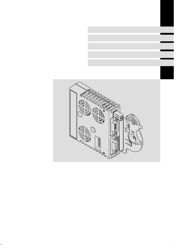
E94YCIB001B
Page 4

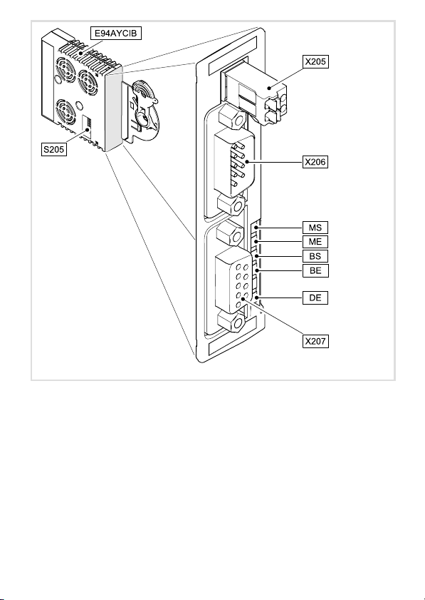
Legende zur Abbildung auf der Ausklappseite
Pos. Beschreibung Ausführliche
S205 DIP−Schalter zur Einstellung der
l Anzahl von Prozessdatenwörtern und Parameterdatenwörtern
l Übertragungsrate
X205 Anschluss für Spannungsversorgung
l 2−polige Steckerleiste mit Federkraftanschluss
X206 INTERBUS−Anschluss, Eingang (IN)
l 9−poliger Sub−D−Stecker
X207 INTERBUS−Anschluss, Ausgang (OUT)
l 9−polige Sub−D−Buchse
MS
ME
BS
LED−Statusanzeigen zur Diagnose 27
BE
DE
0Abb. 0Tab. 0
Information
22
20
16
4
EDK94AYCIB DE/EN/FR/ES/IT 1.0
Page 5

Inhalt i
1 Über diese Dokumentation 6 . . . . . . . . . . . . . . . . . . . . . . . . . . . . . . . . . . . . . . . . . .
Verwendete Konventionen 7 . . . . . . . . . . . . . . . . . . . . . . . . . . . . . . . . . . . . . . . . . .
Verwendete Hinweise 8 . . . . . . . . . . . . . . . . . . . . . . . . . . . . . . . . . . . . . . . . . . . . . . .
2 Sicherheitshinweise 9 . . . . . . . . . . . . . . . . . . . . . . . . . . . . . . . . . . . . . . . . . . . . . . . .
3 Produktbeschreibung 10 . . . . . . . . . . . . . . . . . . . . . . . . . . . . . . . . . . . . . . . . . . . . . . .
Funktion 10 . . . . . . . . . . . . . . . . . . . . . . . . . . . . . . . . . . . . . . . . . . . . . . . . . . . . . . . . . .
Bestimmungsgemäße Verwendung 10 . . . . . . . . . . . . . . . . . . . . . . . . . . . . . . . . . . .
Lieferumfang 10 . . . . . . . . . . . . . . . . . . . . . . . . . . . . . . . . . . . . . . . . . . . . . . . . . . . . . .
Identifikation 11 . . . . . . . . . . . . . . . . . . . . . . . . . . . . . . . . . . . . . . . . . . . . . . . . . . . . . .
4 Technische Daten 12 . . . . . . . . . . . . . . . . . . . . . . . . . . . . . . . . . . . . . . . . . . . . . . . . . .
Allgemeine Daten 12 . . . . . . . . . . . . . . . . . . . . . . . . . . . . . . . . . . . . . . . . . . . . . . . . .
Abmessungen 13 . . . . . . . . . . . . . . . . . . . . . . . . . . . . . . . . . . . . . . . . . . . . . . . . . . . . .
5 Mechanische Installation 14 . . . . . . . . . . . . . . . . . . . . . . . . . . . . . . . . . . . . . . . . . . . .
6 Elektrische Installation 15 . . . . . . . . . . . . . . . . . . . . . . . . . . . . . . . . . . . . . . . . . . . . . .
EMV−gerechte Verdrahtung 15 . . . . . . . . . . . . . . . . . . . . . . . . . . . . . . . . . . . . . . . . . .
INTERBUS−Anschluss 16 . . . . . . . . . . . . . . . . . . . . . . . . . . . . . . . . . . . . . . . . . . . . . . . .
Abmessungen 9−polige Sub−D−Steckverbinder 18 . . . . . . . . . . . . . . . . . . . . . . . . . . .
Kabelspezifikation 19 . . . . . . . . . . . . . . . . . . . . . . . . . . . . . . . . . . . . . . . . . . . . . . . . .
Externe Spannungsversorgung 20 . . . . . . . . . . . . . . . . . . . . . . . . . . . . . . . . . . . . . .
7 Inbetriebnahme 21 . . . . . . . . . . . . . . . . . . . . . . . . . . . . . . . . . . . . . . . . . . . . . . . . . . .
Vor dem ersten Einschalten 21 . . . . . . . . . . . . . . . . . . . . . . . . . . . . . . . . . . . . . . . . . .
Einstellmöglichkeiten durch DIP−Schalter 22 . . . . . . . . . . . . . . . . . . . . . . . . . . . . . . .
8 Diagnose 27 . . . . . . . . . . . . . . . . . . . . . . . . . . . . . . . . . . . . . . . . . . . . . . . . . . . . . . . . .
LED−Statusanzeigen 27 . . . . . . . . . . . . . . . . . . . . . . . . . . . . . . . . . . . . . . . . . . . . . . . .
EDK94AYCIB DE/EN/FR/ES/IT 1.0
5
Page 6

1 Über diese Dokumentation
1 Über diese Dokumentation
Inhalt
Diese Dokumentation enthält ...
ƒ Informationen zur mechanischen und elektrischen Installation des
Kommunikationsmoduls;
ƒ Sicherheitshinweise, die Sie unbedingt beachten müssen;
ƒ Angaben über Versionsstände der zu verwendenden Lenze Grundgeräte.
Informationen zur Gültigkeit
Die Informationen in dieser Dokumentation sind gültig für folgende Geräte:
Erweiterungsmodul Typenbezeichnung ab Hardwarestand ab Softwarestand
Kommunikationsmodul
INTERBUS
Zielgruppe
Diese Dokumentation wendet sich an Personen, die das beschriebene Produkt nach Projektvorgabe installieren und in Betrieb nehmen.
E94AYCIB PA 01.00
Tipp!
Dokumentationen und Software−Updates zu weiteren Lenze Produkten finden
Sie im Internet im Bereich "Services & Downloads" unter
http://www.Lenze.com
6
EDK94AYCIB DE/EN/FR/ES/IT 1.0
Page 7

Über diese Dokumentation
Verwendete Konventionen
Verwendete Konventionen
Diese Dokumentation verwendet folgende Konventionen zur Unterscheidung verschiedener Arten von Information:
Informationsart Auszeichnung Beispiele/Hinweise
Zahlenschreibweise
Dezimaltrennzeichen
Symbole
Seitenverweis
Punkt Es wird generell der Dezimalpunkt
verwendet.
Beispiel: 1234.56
Verweis auf eine andere Seite mit zusätzlichen Informationen
Beispiel: 16 = siehe Seite 16
1
EDK94AYCIB DE/EN/FR/ES/IT 1.0
7
Page 8

1 Über diese Dokumentation
Verwendete Hinweise
Verwendete Hinweise
Um auf Gefahren und wichtige Informationen hinzuweisen, werden in dieser Dokumentation folgende Piktogramme und Signalwörter verwendet:
Sicherheitshinweise
Aufbau der Sicherheitshinweise:
Gefahr!
(kennzeichnet die Art und die Schwere der Gefahr)
Hinweistext
(beschreibt die Gefahr und gibt Hinweise, wie sie vermieden werden kann)
Piktogramm und Signalwort Bedeutung
Gefahr von Personenschäden durch gefährliche elektrische Spannung
Gefahr!
Gefahr!
Stop!
Anwendungshinweise
Piktogramm und Signalwort Bedeutung
Hinweis auf eine unmittelbar drohende Gefahr, die den
Tod oder schwere Verletzungen zur Folge haben kann,
wenn nicht die entsprechenden Maßnahmen getroffen
werden.
Gefahr von Personenschäden durch eine allgemeine Gefahrenquelle
Hinweis auf eine unmittelbar drohende Gefahr, die den
Tod oder schwere Verletzungen zur Folge haben kann,
wenn nicht die entsprechenden Maßnahmen getroffen
werden.
Gefahr von Sachschäden
Hinweis auf eine mögliche Gefahr, die Sachschäden zur
Folge haben kann, wenn nicht die entsprechenden Maßnahmen getroffen werden.
Hinweis!
Tipp!
8
Wichtiger Hinweis für die störungsfreie Funktion
Nützlicher Tipp für die einfache Handhabung
Verweis auf andere Dokumentation
EDK94AYCIB DE/EN/FR/ES/IT 1.0
Page 9

Sicherheitshinweise 2
2 Sicherheitshinweise
Gefahr!
Unsachgemäßer Umgang mit dem Kommunikationsmodul und dem
Grundgerät kann schwere Personenschäden und Sachschäden verursachen.
Beachten Sie die in der Dokumentation zum Grundgerät enthaltenen
Sicherheitshinweise und Restgefahren.
Stop!
Elektrostatische Entladung
Durch elektrostatische Entladung können elektronische Bauteile innerhalb des
Kommunikationsmoduls beschädigt oder zerstört werden.
Mögliche Folgen:
ƒ Das Kommunikationsmodul ist defekt.
ƒ Die Feldbus−Kommunikation ist nicht möglich oder fehlerhaft.
Schutzmaßnahmen
ƒ Befreien Sie sich vor dem Berühren des Moduls von elektrostatischen
Aufladungen.
EDK94AYCIB DE/EN/FR/ES/IT 1.0
9
Page 10

3 Produktbeschreibung
Funktion
3 Produktbeschreibung
Funktion
Das Kommunikationsmodul koppelt Lenze Servo Drives 9400 an das Kommunikationssystem INTERBUS.
Bestimmungsgemäße Verwendung
Das Kommunikationsmodul ...
ƒ ist eine Zubehör−Baugruppe, die mit folgenden Lenze Grundgeräten eingesetzt
werden kann:
Produktreihe Typenbezeichnung ab Hardwarestand ab Softwarestand
Servo Drives 9400
HighLine
ƒ ist ein Betriebsmittel zum Einsatz in industriellen Starkstromanlagen.
ƒ nur in INTERBUS−Netzwerken einsetzen.
Jede andere Verwendung gilt als sachwidrig!
E94AxHxxxxx 1A 03.00
Lieferumfang
ƒ Kommunikationsmodul E94AYCIB
ƒ Montageanleitung
Tipp!
Weiterführende Informationen zu diesem Kommunikationsmodul finden Sie
im entsprechenden Kommunikationshandbuch.
Die PDF−Datei finden Sie im Internet im Bereich "Services & Downloads" unter
http://www.Lenze.com
10
EDK94AYCIB DE/EN/FR/ES/IT 1.0
Page 11

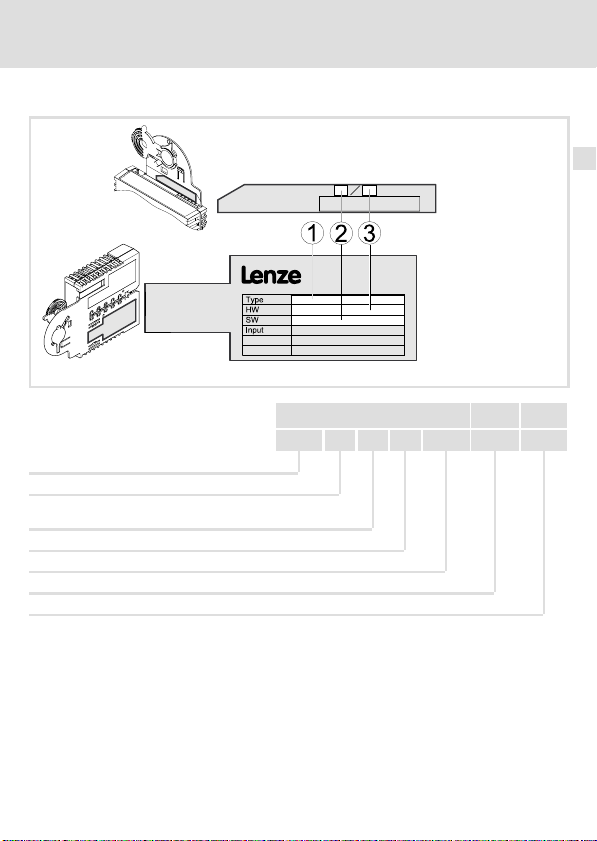
Identifikation
Produktreihe
Gerätegeneration
Modulkennung: Erweiterungsmodul
Modultyp: Kommunikationsmodul
INTERBUS
Hardwarestand
Softwarestand
Produktbeschreibung
Identifikation
E94YCIB005
E94 A Y C IB PA 01.00
3
EDK94AYCIB DE/EN/FR/ES/IT 1.0
11
Page 12

4 Technische Daten
Allgemeine Daten
4 Technische Daten
Allgemeine Daten
Bereich Werte
Bestell−Bezeichnung E94AYCIB
Kommunikationsprofil INTERBUS
Schnittstellen
Kommunikationsmedium RS485
Netzwerktopologie Ring
INTERBUS−Teilnehmeranzahl
Übertragungsrate 500 kBit/s oder 2 MBit/s
Max. Leitungslänge
INTERBUS−Teilnehmer Slave
Spannungsversorgung Externe Versorgung über die 2−polige Steckerleiste
Konformitäten, Approbationen
l Eingang (IN): 9−poliger Sub−D−Stecker
l Ausgang (OUT): 9−polige Sub−D−Buchse
l 1 Master
l 512 Slaves
(über DIP−Schalter oder Codestelle einstellbar)
l 400 m bei 500 kBit/s
l 150 m bei 2 MBit/s
(jeweils zwischen den einzelnen INTERBUS−Teilnehmern)
l "+": U = 24 V DC (+/− 10 %), Imax = 180 mA
l "−": Bezugspotenzial für externe Spannungsversorgung
CE
Gerätehandbuch "Servo Drives 9400"
Hier finden Sie die Umgebungsbedingungen und Daten zur
Elektromagnetischen Verträglichkeit (EMV), die auch für das
Kommunikationsmodul gelten.
12
EDK94AYCIB DE/EN/FR/ES/IT 1.0
Page 13
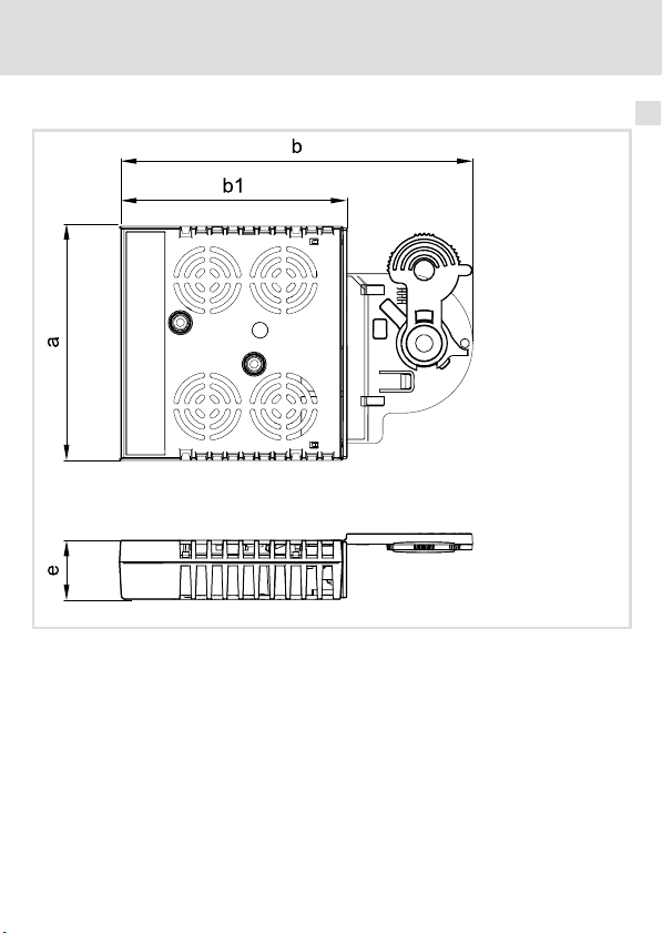
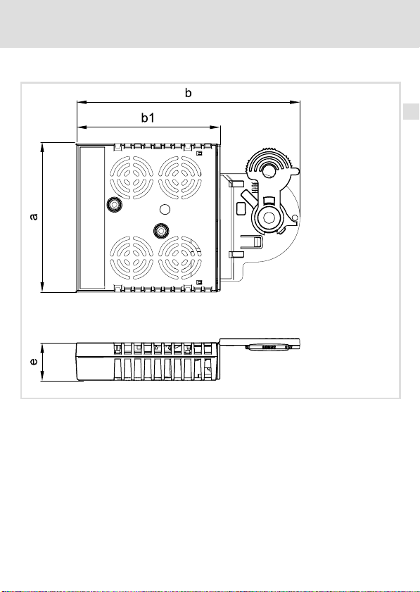
Abmessungen
a89 mm
b 134 mm
b1 87 mm
e 23 mm
Technische Daten
Abmessungen
E94YCXX005
4
EDK94AYCIB DE/EN/FR/ES/IT 1.0
13
Page 14
5 Mechanische Installation
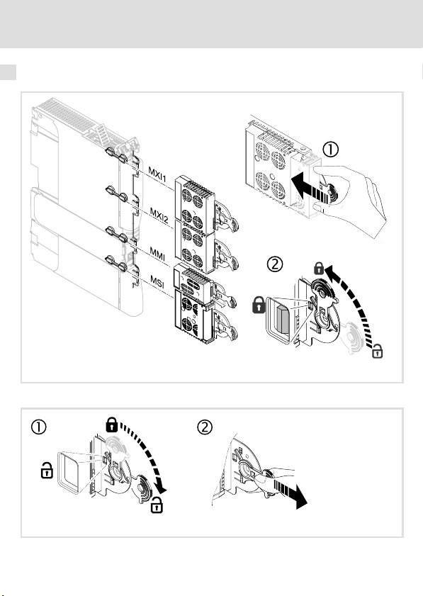
5 Mechanische Installation
Montage
Demontage
E94YCXX001G
14
E94AYCXX001H
EDK94AYCIB DE/EN/FR/ES/IT 1.0
Page 15
Elektrische Installation
EMV−gerechte Verdrahtung
6 Elektrische Installation
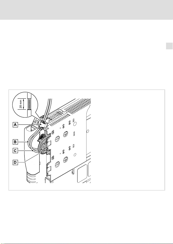
EMV−gerechte Verdrahtung
In typischen Anlagen ist die standardmäßige Schirmung des INTERBUS−Kabels ausreichend.
In sehr stark gestörten Umgebungen kann eine Verbesserung der EMV−Festigkeit durch
eine zusätzliche Erdung des Kabelschirms ermöglicht werden.
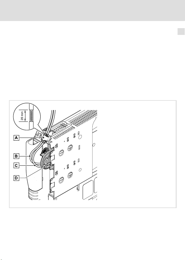
Beachten Sie dazu folgende Hinweise:
1. Der Abstand der zusätzlichen Erdung der INTERBUS−Stecker (Sub−D, 9−polig) ist
abhängig vom Steckplatz des Moduls. Der Abstand beträgt ...
– ca. 10 cm für den oberen Steckplatz (MXI1);
– ca. 20 cm für den unteren Steckplatz (MXI2).
2. Entfernen Sie ausgehend von diesem Abstand die Kunststoffumhüllung des Kabels
auf einer Länge von 2 cm.
3. Befestigen Sie den Kabelschirm am Schirmblech des Servo Drive 9400.
6
Befestigung am Schirmblech des Servo Drive 9400
INTERBUS−Leitung an X206 (IN)
INTERBUS−Leitung an X207 (OUT)
Kommunikationsmodul in Steckplatz MXI1 des Servo Drive 9400
EDK94AYCIB DE/EN/FR/ES/IT 1.0
E94YCXX008
15
Page 16
6 Elektrische Installation
INTERBUS−Anschluss
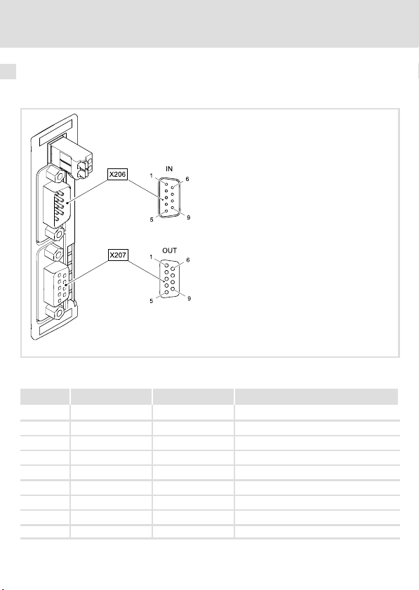
INTERBUS−Anschluss
Der INTERBUS−Anschluss des Kommunikationsmoduls erfolgt über X206 (Eingang, 9−poliger Sub−D−Stecker) und X207 (Ausgang, 9−polige Sub−D−Buchse).
Belegung des 9−poligen Sub−D−Steckers X206 (IN)
Pin Bezeichnung Ein−/Ausgang Beschreibung
1 DO1 Eingang RS485: DO1 nicht invertiert
2 DI1 Ausgang RS485: DI1 nicht invertiert
3 GND Bezugspotenzial
4 frei nicht belegt
5 Vcc5 Ausgang 5 V DC
6 /DO1 Eingang RS485: DO1 invertiert
7 /DI1 Ausgang RS485: DI1 invertiert
8 Vcc5 Ausgang 5 V DC
9 frei nicht belegt
16
EDK94AYCIB DE/EN/FR/ES/IT 1.0
E94YCIB001C
Page 17

Elektrische Installation
INTERBUS−Anschluss
Belegung der 9−poligen Sub−D−Buchse X207 (OUT)
Pin Bezeichnung Ein−/Ausgang Beschreibung
1 DO2 Ausgang RS485: DO2 nicht invertiert
2 DI2 Eingang RS485: DI2 nicht invertiert
3
4
5 Vcc5 Ausgang 5 V DC
6 /DO2 Ausgang RS485: DO2 invertiert
7 /DI2 Eingang RS485: DI2 invertiert
8 Vcc5 Ausgang 5 V DC
9 RBST Melde−Eingang Verbindung zum abgehenden INTERBUS
GND
GND
Bezugspotenzial
gesteckt.
6
EDK94AYCIB DE/EN/FR/ES/IT 1.0
17
Page 18

6 Elektrische Installation
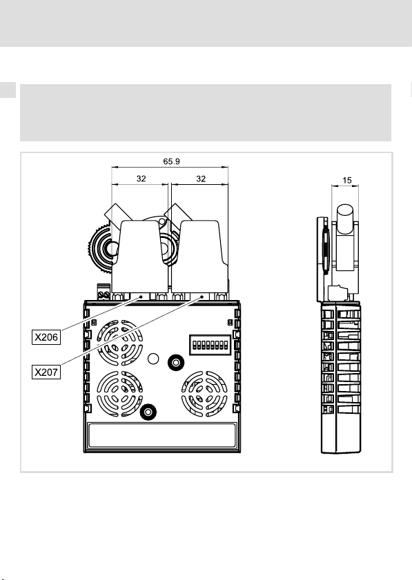
Abmessungen 9−polige Sub−D−Steckverbinder
Abmessungen 9−polige Sub−D−Steckverbinder
Hinweis!
Halten Sie die Abmessungen der 9−poligen Sub−D−Steckverbinder für die
INTERBUS−Anschlüsse X206/X207 ein.
18
E94YCIB001G
EDK94AYCIB DE/EN/FR/ES/IT 1.0
Page 19

Elektrische Installation
Kabelspezifikation
Kabelspezifikation
Allgemeine Eigenschaften
Kabeltyp Meterware,
Leiteranzahl 3 × 2, paarig verseilt, mit gemeinsamer Abschirmung
Leiterquerschnitt > 0.2 mm
DC−Leitungswiderstand
Impedanz (charakteristisch)
Kapazitätsbelag < 60 nF/km (f = 800 Hz)
Busleitungslänge
Passen Sie die Übertragungsrate entsprechend der Länge des Buskabels an:
Übertragungsrate Leitungslänge zwischen den einzelnen INTERBUS−Teilnehmern
500 kBit/s 400 m
2 MBit/s 150 m
(z. B. PHOENIX CONTACT: IBS RBC Meter−T, Best.−Nr.
28 06 28 6)
2
< 96 W/km
l 120 W ± 20 % (f = 64 kHz)
l 100 W ± 15 W (f > 1 MHz)
Hinweis!
Die von Datenmenge, Zykluszeit und Teilnehmeranzahl abhängige
Übertragungsrate nur so hoch wählen, wie es für die Anwendung erforderlich
ist.
6
EDK94AYCIB DE/EN/FR/ES/IT 1.0
19
Page 20
6 Elektrische Installation
Externe Spannungsversorgung
Externe Spannungsversorgung
Das Kommunikationsmodul kann extern über separate Versorgungsleitungen an der 2−poligen Steckerleiste (X205) mit Spannung versorgt werden.
Hinweis!
Verwenden Sie bei externer Spannungsversorgung und bei größeren
Entfernungen zwischen den Schaltschränken in jedem Schaltschrank immer
ein separates und nach EN 61800−5−1 sicher getrenntes Netzteil
("SELV"/"PELV").
ƒ Die externe Spannungsversorgung des Kommunikationsmoduls ist notwendig, wenn
beim Ausfall der Versorgung des Grundgerätes die Kommunikation über den Bus
bestehen bleiben soll.
ƒ Der Zugriff auf Parameter eines vom Netz getrennten Grundgerätes ist nicht
möglich.
Belegung der Steckerleiste X205
Steckerleiste Erläuterung
Anschluss "+" U = 24VDC (21.6 V − 0% ... 26.4 V + 0 %)
Anschluss "−" Bezugspotential für externe Spannungsversorgung
Daten der Anschlussklemmen
Bereich Werte
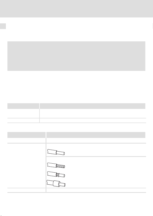
Elektrischer Anschluss 2−polige Steckerleiste mit Federkraftanschluss
Anschlussmöglichkeiten
Abisolierlänge
I = 180 mA
starr:
flexibel:
10 mm
0.2 ... 1.5 mm
ohne Aderendhülse
0.2 ... 1.5 mm
mit Aderendhülse, ohne Kunststoffhülse
0.2 ... 1.5 mm
mit Aderendhülse, mit Kunststoffhülse
0.2 ... 1.5 mm
2
(AWG 24 ... 16)
2
(AWG 24 ... 16)
2
(AWG 24 ... 16)
2
(AWG 24 ... 16)
20
EDK94AYCIB DE/EN/FR/ES/IT 1.0
Page 21

Inbetriebnahme
Vor dem ersten Einschalten
7 Inbetriebnahme
Vor dem ersten Einschalten
Stop!
Bevor Sie das Grundgerät mit dem Kommunikationsmodul erstmalig
einschalten, überprüfen Sie die gesamte Verdrahtung auf Vollständigkeit,
Kurzschluss und Erdschluss.
7
EDK94AYCIB DE/EN/FR/ES/IT 1.0
21
Page 22
7 Inbetriebnahme
Einstellmöglichkeiten durch DIP−Schalter
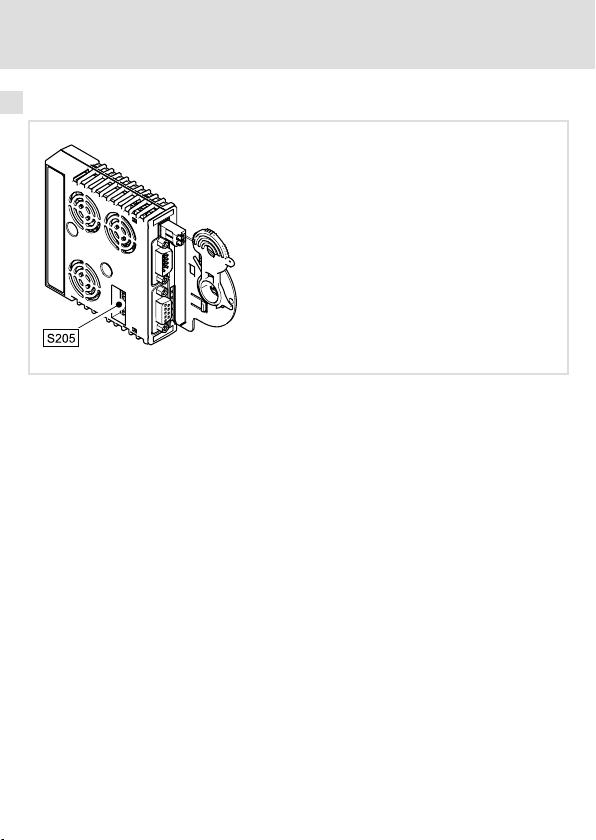
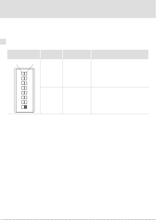
Einstellmöglichkeiten durch DIP−Schalter
Über den DIP−Schalter (S205) können eingestellt werden:
ƒ Anzahl der Prozessdatenwörter (PD) mit Schalter 1 ... 4
ƒ Anzahl der Parameterdatenwörter (PCP) mit Schalter 5 und 6
ƒ Übertragungsrate mit Schalter 8
Lenze−Einstellung: alle Schalter "OFF"
DIP−Schalter 7 hat keine Funktion.
E94YCIB001D
22
EDK94AYCIB DE/EN/FR/ES/IT 1.0
Page 23

Einstellmöglichkeiten durch DIP−Schalter
Hinweis!
Um geänderte Einstellungen zu aktivieren, schalten Sie die
Spannungsversorgung des Kommunikationsmoduls aus und anschließend
wieder ein.
Die Einstellungen können Sie auch über Codestellen vornehmen:
ƒ Alle DIP−Schalter = "OFF" (Lenze−Einstellung):
Beim Einschalten wird die Konfiguration aus den Codestellen
C13892/C14892, C13893/C14893 und C13894/C14894 aktiv.
ƒ Mindestens ein DIP−Schalter = "ON":
Beim Einschalten werden die Werte aus den Schalterstellungen
übernommen.
Die Datenwortsumme (PD + PCP) darf maximal 10 Wörter betragen.
Inbetriebnahme
7
EDK94AYCIB DE/EN/FR/ES/IT 1.0
23
Page 24
7 Inbetriebnahme
Einstellmöglichkeiten durch DIP−Schalter
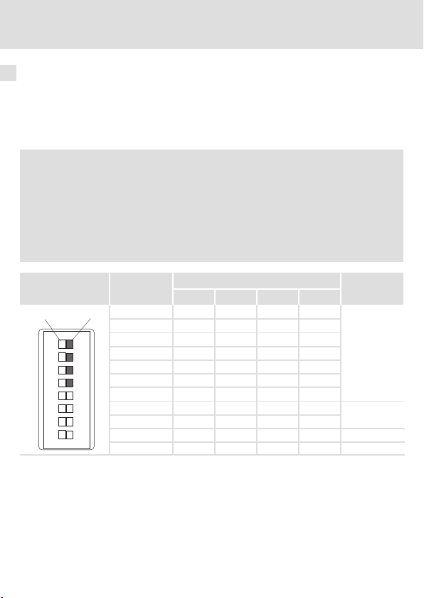
Anzahl der Prozessdatenwörter (PD) einstellen
ƒ Die Anzahl der Prozessdatenwörter können Sie über die Schalter 1 ... 4 oder die
Codestelle C13893 / C14893 einstellen.
ƒ 0 ... 10 Prozessdatenwörter können verwendet werden.
ƒ Die aktuelle Einstellung wird in C13860/2 / C14860/2 angezeigt.
Hinweis!
Die Datenwortsumme (PD + PCP) muss 1 ... 10 Wörter betragen. Unzulässige
Einstellungen werden durch die LED "BE" (blinkt rot, 27) signalisiert.
Das Kommunikationsmodul arbeitet dann intern mit folgenden Werten
weiter:
ƒ PD = 2 (Wörter)
ƒ PCP = 1 (Wort)
DIP−Schalter Anzahl PD
OFF
ON
12345678
24
Schalter
0 OFF OFF OFF OFF
1 OFF OFF OFF ON
2 OFF OFF ON OFF
3 OFF OFF ON ON
4 OFF ON OFF OFF
5 OFF ON OFF ON
6 OFF ON ON OFF
7 OFF ON ON ON
8 ON OFF OFF OFF
9 ON OFF OFF ON 1
10 ON OFF ON OFF 0
1 2 3 4
EDK94AYCIB DE/EN/FR/ES/IT 1.0
Max. Anzahl
PCP
4
2
Page 25
Einstellmöglichkeiten durch DIP−Schalter
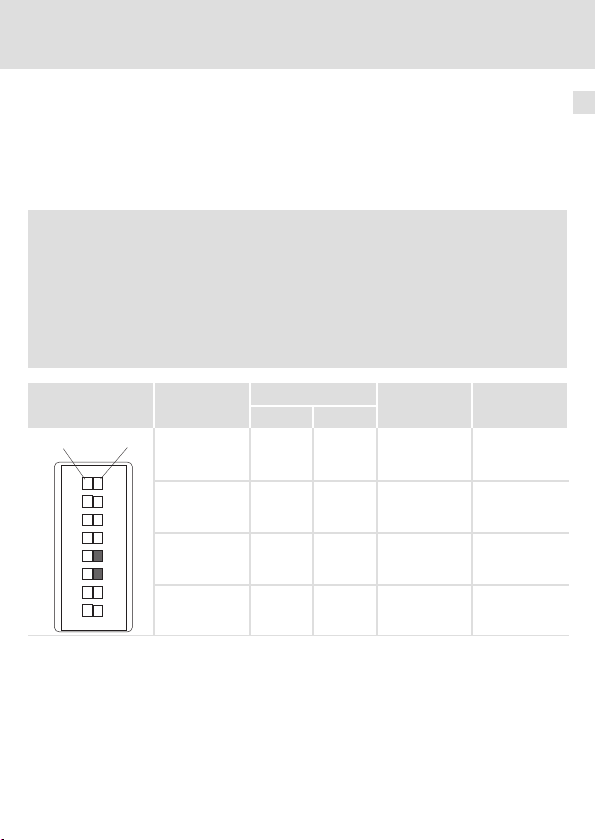
Anzahl der Parameterdatenwörter (PCP) einstellen
ƒ Die Anzahl der Parameterdatenwörter können Sie über die Schalter 5 und 6 oder die
Codestelle C13892 / C14892 einstellen.
ƒ 0, 1, 2 oder 4 Parameterdatenwörter können verwendet werden.
ƒ Die aktuelle Einstellung wird in C13860/1 / C14860/1 angezeigt.
Hinweis!
Die Datenwortsumme (PD + PCP) muss 1 ... 10 Wörter betragen. Unzulässige
Einstellungen werden durch die LED "BE" (blinkt rot, 27) signalisiert.
Das Kommunikationsmodul arbeitet dann intern mit folgenden Werten
weiter:
ƒ PD = 2 (Wörter)
ƒ PCP = 1 (Wort)
Inbetriebnahme
7
DIP−Schalter Anzahl PCP
OFF
ON
12345678
EDK94AYCIB DE/EN/FR/ES/IT 1.0
Schalter
5 6
0 OFF OFF 10 0x03
1 OFF ON 9 0xE3
2 ON OFF 8 0xE0
4 ON ON 6 0xE1
Max. Anzahl PD ID−Code
[hex]
25
Page 26

7 Inbetriebnahme
Einstellmöglichkeiten durch DIP−Schalter
Übertragungsrate einstellen
ƒ Die Übertragungsrate können Sie über den Schalter 8 oder die Codestelle C13894 /
C14894 einstellen.
ƒ Die aktuelle Einstellung der Übertragungsrate wird in C13863 / C14863 angezeigt.
DIP−Schalter Schalter 8 Übertragungsrate Maximale Leitungslänge zwischen
OFF
ON
12345678
OFF 500 kBit/s 400 m
ON 2 MBit/s 150 m
benachbarten Teilnehmern
26
EDK94AYCIB DE/EN/FR/ES/IT 1.0
Page 27
Diagnose
LED−Statusanzeigen
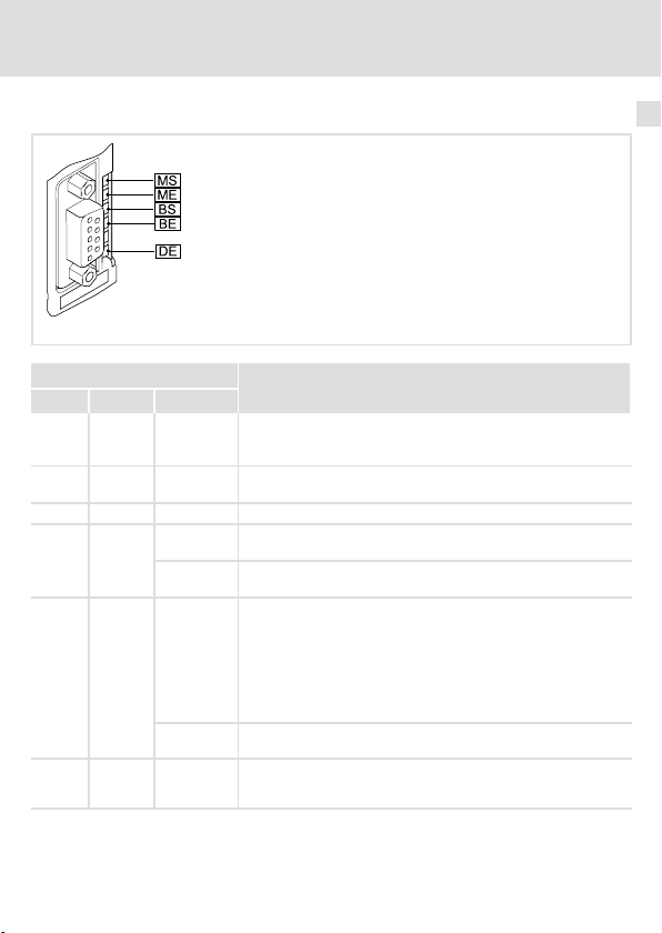
8 Diagnose
LED−Statusanzeigen
E94YCIB001F
LED
Pos. Farbe Zustand
MS grün blinkt Das Kommunikationsmodul ist mit Spannung versorgt, hat aber
MS grün an Das Kommunikationsmodul ist mit Spannung versorgt und hat
ME rot an Es liegt ein Fehler im Bereich des Kommunikationsmoduls vor.
BS grün
BE rot
DE rot an Das Kommunikationsmodul wird vom Grundgerät nicht akzep-
aus Das Kommunikationsmodul ist am Feldbus nicht aktiv. Datenzy-
blinkt Die Kommunikation über das Kommunikationsmodul ist aufge-
blinkt Unzulässige Einstellung:
an INTERBUS−Kommunikation unterbrochen. Datenzyklen werden
Beschreibung
keine Verbindung zum Grundgerät. (Das Grundgerät ist ausgeschaltet, in der Initialisierungsphase oder nicht vorhanden.)
eine Verbindung zum Grundgerät.
klen werden nicht ausgeführt.
baut. Der INTERBUS ist aktiv. Datenzyklen werden ausgeführt.
l Datenwortsumme (PD + PCP) > 10
l Datenwortsumme (PD + PCP) = 0
Das Kommunikationsmodul ist initialisiert und arbeitet intern mit
den folgenden Werten weiter:
l PD = 2 (Wörter)
l PCP = 1 (Wort)
nicht ausgeführt.
tiert (siehe Hinweise in der Dokumentation zum Grundgerät) oder
das Grundgerät ist nicht aktiv.
8
EDK94AYCIB DE/EN/FR/ES/IT 1.0
27
Page 28

Legend for fold−out page
Pos. Description Detailed
S205 DIP switch for setting the
l number of process data words and parameter data words
l Baud rate
X205 Connection for voltage supply
l 2−pin plug connector with spring connection
X206 INTERBUS connection, input (IN)
l 9−pin Sub−D connector
X207 INTERBUS connection, output (OUT)
l 9−pin Sub−D socket
MS
ME
BS
LED status indicators for diagnostics 51
BE
DE
0Fig. 0Tab. 0
information
46
44
40
28
EDK94AYCIB DE/EN/FR/ES/IT 1.0
Page 29

Contents i
1 About this documentation 30 . . . . . . . . . . . . . . . . . . . . . . . . . . . . . . . . . . . . . . . . . . .
Conventions used 31 . . . . . . . . . . . . . . . . . . . . . . . . . . . . . . . . . . . . . . . . . . . . . . . . . .
Notes used 32 . . . . . . . . . . . . . . . . . . . . . . . . . . . . . . . . . . . . . . . . . . . . . . . . . . . . . . . .
2 Safety instructions 33 . . . . . . . . . . . . . . . . . . . . . . . . . . . . . . . . . . . . . . . . . . . . . . . . .
3 Product description 34 . . . . . . . . . . . . . . . . . . . . . . . . . . . . . . . . . . . . . . . . . . . . . . . . .
Function 34 . . . . . . . . . . . . . . . . . . . . . . . . . . . . . . . . . . . . . . . . . . . . . . . . . . . . . . . . .
Application as directed 34 . . . . . . . . . . . . . . . . . . . . . . . . . . . . . . . . . . . . . . . . . . . . . .
Scope of supply 34 . . . . . . . . . . . . . . . . . . . . . . . . . . . . . . . . . . . . . . . . . . . . . . . . . . . .
Identification 35 . . . . . . . . . . . . . . . . . . . . . . . . . . . . . . . . . . . . . . . . . . . . . . . . . . . . . .
4 Technical data 36 . . . . . . . . . . . . . . . . . . . . . . . . . . . . . . . . . . . . . . . . . . . . . . . . . . . . .
General Data 36 . . . . . . . . . . . . . . . . . . . . . . . . . . . . . . . . . . . . . . . . . . . . . . . . . . . . . .
Dimensions 37 . . . . . . . . . . . . . . . . . . . . . . . . . . . . . . . . . . . . . . . . . . . . . . . . . . . . . . .
5 Mechanical installation 38 . . . . . . . . . . . . . . . . . . . . . . . . . . . . . . . . . . . . . . . . . . . . .
6 Electrical installation 39 . . . . . . . . . . . . . . . . . . . . . . . . . . . . . . . . . . . . . . . . . . . . . . .
Wiring according to EMC 39 . . . . . . . . . . . . . . . . . . . . . . . . . . . . . . . . . . . . . . . . . . . .
INTERBUS connection 40 . . . . . . . . . . . . . . . . . . . . . . . . . . . . . . . . . . . . . . . . . . . . . . .
Dimensions 9−pin Sub−D connector 42 . . . . . . . . . . . . . . . . . . . . . . . . . . . . . . . . . . . .
Cable specification 43 . . . . . . . . . . . . . . . . . . . . . . . . . . . . . . . . . . . . . . . . . . . . . . . . .
External voltage supply 44 . . . . . . . . . . . . . . . . . . . . . . . . . . . . . . . . . . . . . . . . . . . .
7 Commissioning 45 . . . . . . . . . . . . . . . . . . . . . . . . . . . . . . . . . . . . . . . . . . . . . . . . . . . .
Before switching on 45 . . . . . . . . . . . . . . . . . . . . . . . . . . . . . . . . . . . . . . . . . . . . . . . .
DIP switch settings 46 . . . . . . . . . . . . . . . . . . . . . . . . . . . . . . . . . . . . . . . . . . . . . . . . .
8 Diagnostics 51 . . . . . . . . . . . . . . . . . . . . . . . . . . . . . . . . . . . . . . . . . . . . . . . . . . . . . . .
LED status displays 51 . . . . . . . . . . . . . . . . . . . . . . . . . . . . . . . . . . . . . . . . . . . . . . . . .
EDK94AYCIB DE/EN/FR/ES/IT 1.0
29
Page 30

1 About this documentation
1 About this documentation
Contents
This documentation contains ...
ƒ information about the mechanical and electrical installation of the communication
module;
ƒ safety instructions which must be followed;
ƒ specifications for the versions of the Lenze standard devices to be used.
Validity information
The information given in this documentation is valid for the following devices:
Extension module Type designation from hardware version from software version
INTERBUS
communication
module
Target group
This documentation is intended for persons who install and commission the described
product according to the project requirements.
E94AYCIB PA 01.00
Tip!
Documentation and software updates for further Lenze products can be found
on the Internet in the "Services & Downloads" area under
http://www.Lenze.com
30
EDK94AYCIB DE/EN/FR/ES/IT 1.0
Page 31

About this documentation
Conventions used
Conventions used
This documentation uses the following conventions to distinguish between different types
of information:
Type of information Identification Examples/notes
Numbers
Decimal separator
Symbols
Page reference
Point The decimal point is used throughout
this documentation.
Example: 1234.56
Reference to another page with
additional information
Example: 16 = see page 16
1
EDK94AYCIB DE/EN/FR/ES/IT 1.0
31
Page 32

1 About this documentation
Notes used
Notes used
The following pictographs and signal words are used in this documentation to indicate
dangers and important information:
Safety instructions
Structure of safety instructions:
Danger!
(characterises the type and severity of danger)
Note
(describes the danger and gives information about how to prevent dangerous
situations)
Pictograph and signal word Meaning
Danger of personal injury through dangerous electrical
voltage.
Danger!
Danger!
Stop!
Application notes
Pictograph and signal word Meaning
Reference to an imminent danger that may result in
death or serious personal injury if the corresponding
measures are not taken.
Danger of personal injury through a general source of
danger.
Reference to an imminent danger that may result in
death or serious personal injury if the corresponding
measures are not taken.
Danger of property damage.
Reference to a possible danger that may result in
property damage if the corresponding measures are not
taken.
Note!
Tip!
32
Important note to ensure troublefree operation
Useful tip for simple handling
Reference to another documentation
EDK94AYCIB DE/EN/FR/ES/IT 1.0
Page 33

Safety instructions 2
2 Safety instructions
Danger!
Inappropriate handling of the communication module and the standard device
can cause serious personal injury and material damage.
Observe the safety instructions and residual hazards described in the
documentation for the standard device.
Stop!
Electrostatic discharge
Electronic components of the communication module can be damaged or
destroyed through electrostatic discharge.
Possible consequences:
ƒ The communication module is damaged.
ƒ Fieldbus communication is not possible or faulty.
Protective measures
ƒ Discharge electrostatic charges before touching the module.
EDK94AYCIB DE/EN/FR/ES/IT 1.0
33
Page 34

3 Product description
Function
3 Product description
Function
The communication module connects Lenze Servo Drives 9400 to the INTERBUS
communication system.
Application as directed
The communication module ...
ƒ is an accessory which can be used in conjunction with the following Lenze standard
devices:
Product series Type designation from hardware version from software version
Servo Drives 9400
HighLine
ƒ is intended for use in industrial power systems.
ƒ is only to be used in INTERBUS networks.
Any other use shall be deemed inappropriate!
E94AxHxxxxx 1A 03.00
Scope of supply
ƒ Communication module E94AYCIB
ƒ Mounting Instructions
Tip!
Further information about this communication module can be found in the
corresponding communication manual.
The pdf file can be found on the Internet in the "Services & Downloads" area
under
http://www.Lenze.com
34
EDK94AYCIB DE/EN/FR/ES/IT 1.0
Page 35

Identification
Product series
Version
Module code: extension module
Module type: communication module
INTERBUS
Hardware version
Software version
Product description
Identification
E94YCIB005
E94 A Y C IB PA 01.00
3
EDK94AYCIB DE/EN/FR/ES/IT 1.0
35
Page 36

4 Technical data
General Data
4 Technical data
General Data
Range Values
Order designation E94AYCIB
Communication profile INTERBUS
Interfaces
Communication medium RS485
Network topology Ring
Number of INTERBUS nodes
Baud rate 500 kBit/s or 2 MBit/s
Max. cable length
INTERBUS node Slave
Voltage supply External supply via the 2−pin plug connector
Conformities, approvals CE
l Input (IN): 9−pin Sub−D connector
l Input (OUT): 9−pin Sub−D socket
l 1 master
l 512 slaves
(adjustable by means of DIP switches or codes)
l 400 m at 500 kBit/s
l 150 m at 2 MBit/s
(between each of the individual INTERBUS nodes)
l "+": U = 24 V DC (+/− 10 %), Imax = 180 mA
l "−": reference potential for external voltage supply
"Servo Drives 9400" hardware manual
Here you can find the ambient conditions and the electromagnetic
compatibility (EMC) specifications applying to the communication module.
36
EDK94AYCIB DE/EN/FR/ES/IT 1.0
Page 37

Dimensions
a89 mm
b 134 mm
b1 87 mm
e 23 mm
Technical data
Dimensions
E94YCXX005
4
EDK94AYCIB DE/EN/FR/ES/IT 1.0
37
Page 38

5 Mechanical installation
5 Mechanical installation
Mounting
Dismounting
E94YCXX001G
38
E94AYCXX001H
EDK94AYCIB DE/EN/FR/ES/IT 1.0
Page 39

Electrical installation
Wiring according to EMC
6 Electrical installation
Wiring according to EMC
In typical installations, the standard shielding of the INTERBUS cable is sufficient.
In environments that are subject to severe interference, electromagnetic compatibility can
be improved by means of an additional PE connection for the cable shield.
Please observe the following instructions:
1. The clearance of the additional PE connection of the INTERBUS connector (Sub−D,
9−pin) depends on the slot of the module. The clearance is ...
– approx. 10 cm for the upper slot (MXI1);
– approx. 20 cm for the lower slot (MXI2).
2. Assuming this clearance, remove a length of 2 cm of plastic sheath from the cable.
3. Connect the cable shield to the shield sheet of the Servo Drive 9400.
6
Connection to the shield sheet of Servo Drive 9400
INTERBUS cable to X206 (IN)
INTERBUS cable to X207 (OUT)
Communication module in slot MXI1 of Servo Drive 9400
EDK94AYCIB DE/EN/FR/ES/IT 1.0
E94YCXX008
39
Page 40

6 Electrical installation
INTERBUS connection
INTERBUS connection
The INTERBUS is connected to the communication module by means of X206 (input, 9−pin
Sub−D connector) and X207 (output, 9−pin Sub−D socket).
Assignment of the 9−pin Sub−D connector X206 (IN)
Pin Designation Input/Output Description
1 DO1 Input RS485: DO1 not inverted
2 DI1 Output RS485: DI1 not inverted
3 GND Reference potential
4 free not assigned
5 Vcc5 Output 5 V DC
6 /DO1 Input RS485: DO1 inverted
7 /DI1 Output RS485: DI1 inverted
8 Vcc5 Output 5 V DC
9 free not assigned
40
EDK94AYCIB DE/EN/FR/ES/IT 1.0
E94YCIB001C
Page 41

Electrical installation
INTERBUS connection
Assignment of the 9−pin Sub−D socket X207 (OUT)
Pin Designation Input/Output Description
1 DO2 Output RS485: DO2 not inverted
2 DI2 Input RS485: DI2 not inverted
3
4
5 Vcc5 Output 5 V DC
6 /DO2 Output RS485: DO2 inverted
7 /DI2 Input RS485: DI2 inverted
8 Vcc5 Output 5 V DC
9 RBST Signal input Connection to outgoing INTERBUS
GND
GND
Reference potential
plugged in.
6
EDK94AYCIB DE/EN/FR/ES/IT 1.0
41
Page 42
6 Electrical installation
Dimensions 9−pin Sub−D connector
Dimensions 9−pin Sub−D connector
Note!
Adhere to the dimensions of the 9−pin Sub−D connector for the INTERBUS ports
X206/X207.
42
E94YCIB001G
EDK94AYCIB DE/EN/FR/ES/IT 1.0
Page 43

Electrical installation
Cable specification
Cable specification
General characteristics
Cable type Sold by the meter,
Number of conductors 3 × 2, twisted pairs, with shared shield
Conductor cross−section > 0.2 mm
DC cable resistance
Impedance (characteristic)
Capacitance per unit length < 60 nF/km (f = 800 Hz)
Bus cable length
Adapt the baud rate to the length of the bus cable:
Baud rate Length of cable between the individual INTERBUS nodes
500 kBit/s 400 m
2 Mbits/s 150 m
(e.g. PHOENIX CONTACT: IBS RBC Meter−T, Order No.
28 06 28 6)
2
< 96 W/km
l 120 W ± 20 % (f = 64 kHz)
l 100 W ±15 W (f > 1 MHz)
Note!
Select a baud rate that matches the data volume, cycle time and number of
nodes and that is as high as is necessary for the application.
6
EDK94AYCIB DE/EN/FR/ES/IT 1.0
43
Page 44

6 Electrical installation
External voltage supply
External voltage supply
The communication module can be supplied with voltage via separate supply leads
connected to the 2−pin plug connector (X205).
Note!
Always use a separate power supply unit in every control cabinet and safely
separate it according to EN 61800−5−1 ("SELV"/"PELV") in case of external
voltage supply and larger distances between the control cabinets.
ƒ The external voltage supply of the communication module is necessary if
communication via the bus is to continue in the event that the power supply to the
standard device is cut off.
ƒ Access to parameters of a standard device disconnected from the mains supply is not
possible.
Assignment of the X205 plug connector
Plug connector Explanation
"+" U = 24V DC (21.6 V − 0% to 26.4 V + 0 %)
"−" Reference potential for external voltage supply
Terminal data
Range Values
Electrical connection 2−pin plug connector with spring connection
Possible connections
Stripping length
I = 180 mA
rigid:
flexible:
10 mm
0.2 to 1.5 mm
without wire end ferrule
0.2 to 1.5 mm
with wire end ferrule, without plastic sleeve
0.2 to 1.5 mm
with wire end ferrule, with plastic sleeve
0.2 to 1.5 mm
2
(AWG 24 to 16)
2
(AWG 24 to 16)
2
(AWG 24 to 16)
2
(AWG 24 to 16)
44
EDK94AYCIB DE/EN/FR/ES/IT 1.0
Page 45

Commissioning
Before switching on
7 Commissioning
Before switching on
Stop!
Before switching on the standard device with the communication module for
the first time, check the entire wiring for completeness, short circuit and earth
fault.
7
EDK94AYCIB DE/EN/FR/ES/IT 1.0
45
Page 46

7 Commissioning
DIP switch settings
DIP switch settings
The DIP switches (S205) can be used for adjustment purposes:
ƒ Number of process data words (PD) with switches 1 to 4
ƒ Number of parameter data words (PCP)with switches 5 and 6
ƒ Baud rate with switch 8
Lenze setting: all switches "OFF"
DIP switch 7 does not perform any function.
E94YCIB001D
46
EDK94AYCIB DE/EN/FR/ES/IT 1.0
Page 47

Note!
Switch off the voltage supply of the communication module and then on
again in order to activate changed settings.
You can also carry out the settings by means of codes:
ƒ All DIP switches = "OFF" (Lenze setting):
When you switch the power on, the configuration determined by the
codes C13892/C14892, C13893/C14893 and C13894/C14894 becomes
active.
ƒ At least one DIP switch = "ON":
When the power is switched on, the values determined by the switch
settings are adopted.
The total number of data words (PD + PCP) must not exceed 10.
Commissioning
DIP switch settings
7
EDK94AYCIB DE/EN/FR/ES/IT 1.0
47
Page 48

7 Commissioning
DIP switch settings
Setting the number of process data words (PD)
ƒ You can use switches 1 to 4 or the code C13893 / C14893 to set the number of
process data words.
ƒ 0 to 10 process data words can be used.
ƒ The current setting is shown in C13860/2 / C14860/2.
Note!
The total number of data words (PD + PCP) must be between 1 and 10.
Impermissible settings are signalled by the "BE" LED (flashes
The communication module then works internally with the following values:
ƒ PD = 2 (words)
ƒ PCP = 1 (word)
51) red.
DIP switch Number of PD
OFF
ON
12345678
48
Switch
0 OFF OFF OFF OFF
1 OFF OFF OFF ON
2 OFF OFF ON OFF
3 OFF OFF ON ON
4 OFF ON OFF OFF
5 OFF ON OFF ON
6 OFF ON ON OFF
7 OFF ON ON ON
8 ON OFF OFF OFF
9 ON OFF OFF ON 1
10 ON OFF ON OFF 0
1 2 3 4
EDK94AYCIB DE/EN/FR/ES/IT 1.0
Max. number
of PCP
4
2
Page 49

Commissioning
DIP switch settings
Setting the number of parameter data words (PCP)
ƒ You can use switches 5 and 6 or the code C13892 / C14892 to set the number of
parameter data words.
ƒ 0, 1, 2 or 4 parameter data words can be used.
ƒ The current setting is shown in C13860/1 / C14860/1.
Note!
The total number of data words (PD + PCP) must be between 1 and 10.
Impermissible settings are signalled by the "BE" LED (flashes
The communication module then works internally with the following values:
ƒ PD = 2 (words)
ƒ PCP = 1 (word)
51) red).
7
DIP switch Number of PCP
OFF
ON
12345678
EDK94AYCIB DE/EN/FR/ES/IT 1.0
Switch
5 6
0 OFF OFF 10 0x03
1 OFF ON 9 0xE3
2 ON OFF 8 0xE0
4 ON ON 6 0xE1
Max. number ofPDID code
[hex]
49
Page 50

7 Commissioning
DIP switch settings
Baud rate setting
ƒ You can use switch 8 or the code C13894 / C14894 to set the baud rate.
ƒ The current setting of the baud rate is shown in C13863 / C14863.
DIP switch Switch 8 Baud rate Maximum cable length between
OFF
ON
12345678
OFF 500 kBit/s 400 m
ON 2 Mbits/s 150 m
neighbouring nodes
50
EDK94AYCIB DE/EN/FR/ES/IT 1.0
Page 51

Diagnostics
LED status displays
8 Diagnostics
LED status displays
E94YCIB001F
LED
Pos. Colour Condition
MS green flashes The communication module is being supplied with voltage but is
MS green on The communication module is being supplied with voltage and is
ME red on There is a fault in the area of the communication module.
BS green
BE red
DE red on The communication module is not accepted by the standard
off The communication module is not active on the field bus. Data
flashes Communication via the communication module has been set up.
flashes Impermissible setting:
on INTERBUS communication interrupted. Data cycles are not being
Description
not connected to the standard device. (The standard device has
been switched off in the initialisation phase or does not exist.)
connected to the standard device.
cycles are not being executed.
The INTERBUS is active. Data cycles are being executed.
l Total number of data words (PD + PCP) > 10
l Total number of data words (PD + PCP) = 0
The communication module has been initialised and is working
internally with the following values:
l PD = 2 (words)
l PCP = 1 (word)
executed.
device (see notes in the documentation for the standard device)
or the standard device is not active.
8
EDK94AYCIB DE/EN/FR/ES/IT 1.0
51
Page 52

Légende de l’illustration de la page dépliante
Pos. Description Informations
S205 Interrupteurs DIP pour le réglage
l du nombre de mots de données process et de mots de données
paramètres
l Vitesse de transmission
X205 Raccordement d’alimentation
l Bornier à lame ressort 2 bornes
X206 Raccordement INTERBUS, entrée (IN)
l Connecteur SUB−D mâle 9 broches
X207 Raccordement INTERBUS, sortie (OUT)
l Connecteur Sub−D femelle 9 broches
MS
ME
BS
Affichages d’état par LED en vue du diagnostic 75
BE
DE
0Fig. 0Tab. 0
détaillées
70
68
64
52
EDK94AYCIB DE/EN/FR/ES/IT 1.0
Page 53

Sommaire i
1 Présentation du document 54 . . . . . . . . . . . . . . . . . . . . . . . . . . . . . . . . . . . . . . . . . . .
Conventions utilisées 55 . . . . . . . . . . . . . . . . . . . . . . . . . . . . . . . . . . . . . . . . . . . . . . .
Consignes utilisées 56 . . . . . . . . . . . . . . . . . . . . . . . . . . . . . . . . . . . . . . . . . . . . . . . . .
2 Consignes de sécurité 57 . . . . . . . . . . . . . . . . . . . . . . . . . . . . . . . . . . . . . . . . . . . . . . .
3 Description du produit 58 . . . . . . . . . . . . . . . . . . . . . . . . . . . . . . . . . . . . . . . . . . . . . .
Fonction 58 . . . . . . . . . . . . . . . . . . . . . . . . . . . . . . . . . . . . . . . . . . . . . . . . . . . . . . . . .
Utilisation conforme à la fonction 58 . . . . . . . . . . . . . . . . . . . . . . . . . . . . . . . . . . . . .
Equipement livré 58 . . . . . . . . . . . . . . . . . . . . . . . . . . . . . . . . . . . . . . . . . . . . . . . . . . .
Identification 59 . . . . . . . . . . . . . . . . . . . . . . . . . . . . . . . . . . . . . . . . . . . . . . . . . . . . . .
4 Spécifications techniques 60 . . . . . . . . . . . . . . . . . . . . . . . . . . . . . . . . . . . . . . . . . . .
Caractéristiques générales 60 . . . . . . . . . . . . . . . . . . . . . . . . . . . . . . . . . . . . . . . . . .
Encombrements 61 . . . . . . . . . . . . . . . . . . . . . . . . . . . . . . . . . . . . . . . . . . . . . . . . . . .
5 Installation mécanique 62 . . . . . . . . . . . . . . . . . . . . . . . . . . . . . . . . . . . . . . . . . . . . . .
6 Installation électrique 63 . . . . . . . . . . . . . . . . . . . . . . . . . . . . . . . . . . . . . . . . . . . . . . .
Câblage conforme CEM 63 . . . . . . . . . . . . . . . . . . . . . . . . . . . . . . . . . . . . . . . . . . . . . .
Raccordement INTERBUS 64 . . . . . . . . . . . . . . . . . . . . . . . . . . . . . . . . . . . . . . . . . . . .
Encombrements des connecteurs Sub−D 9 broches 66 . . . . . . . . . . . . . . . . . . . . . . .
Spécifications du câble 67 . . . . . . . . . . . . . . . . . . . . . . . . . . . . . . . . . . . . . . . . . . . . .
Alimentation externe 68 . . . . . . . . . . . . . . . . . . . . . . . . . . . . . . . . . . . . . . . . . . . . . .
7 Mise en service 69 . . . . . . . . . . . . . . . . . . . . . . . . . . . . . . . . . . . . . . . . . . . . . . . . . . . .
Avant la première mise sous tension 69 . . . . . . . . . . . . . . . . . . . . . . . . . . . . . . . . . . .
Réglages possibles par interrupteurs DIP 70 . . . . . . . . . . . . . . . . . . . . . . . . . . . . . . .
8 Diagnostic 75 . . . . . . . . . . . . . . . . . . . . . . . . . . . . . . . . . . . . . . . . . . . . . . . . . . . . . . . .
Affichage d’état par LED 75 . . . . . . . . . . . . . . . . . . . . . . . . . . . . . . . . . . . . . . . . . . . . .
EDK94AYCIB DE/EN/FR/ES/IT 1.0
53
Page 54

1 Présentation du document
1 Présentation du document
Contenu
Ce document contient ...
ƒ des informations sur l’installation mécanique et électrique du module de
communication ;
ƒ des consignes de sécurité qui doivent impérativement être respectées ;
ƒ des indications sur les versions des appareils de base Lenze à utiliser.
Informations relatives à la validité
Les informations contenues dans le présent document s’appliquent aux appareils suivants :
Module d’extension Référence de
Module de
communication
INTERBUS
Groupe cible
Ce document est destiné aux personnes chargées d’installer et de mettre en service le
produit décrit selon les exigences du projet.
commande
E94AYCIB PA 01.00
A partir de la version
matérielle
A partir de la version
logicielle
Conseil !
Les mises à jour de logiciels et les documentations relatives aux produits Lenze
sont disponibles dans la zone "Téléchargements" du site Internet :
http://www.Lenze.com
54
EDK94AYCIB DE/EN/FR/ES/IT 1.0
Page 55

Présentation du document
Conventions utilisées
Conventions utilisées
Pour faire la distinction entre différents types d’informations, ce document utilise les
conventions suivantes :
Type d’information Marquage Exemples/remarques
Représentation des chiffres
Séparateur décimal
Symboles
Renvoi à une page
Point Le point décimal est généralement
utilisé.
Exemple : 1234.56
Renvoi à une autre page présentant
des informations supplémentaires
Exemple : 16 = voir page 16
1
EDK94AYCIB DE/EN/FR/ES/IT 1.0
55
Page 56

1 Présentation du document
Consignes utilisées
Consignes utilisées
Pour indiquer des risques et des informations importantes, la présente documentation
utilise les mots et symboles suivants :
Consignes de sécurité
Présentation des consignes de sécurité
Danger !
(Le pictogramme indique le type de risque.)
Explication
(L’explication décrit le risque et les moyens de l’éviter.)
Pictogramme et mot associé Explication
Situation dangereuse pour les personnes en raison d’une
tension électrique élevée
Danger !
Danger !
Stop !
Consignes d’utilisation
Pictogramme et mot associé Explication
Remarque importante !
Indication d’un danger imminent qui peut avoir pour
conséquences des blessures mortelles ou très graves en
cas de non−respect des consignes de sécurité
correspondantes
Situation dangereuse pour les personnes en raison d’un
danger d’ordre général
Indication d’un danger imminent qui peut avoir pour
conséquences des blessures mortelles ou très graves en
cas de non−respect des consignes de sécurité
correspondantes
Risques de dégâts matériels
Indication d’un risque potentiel qui peut avoir pour
conséquences des dégâts matériels en cas de non−respect
des consignes de sécurité correspondantes
Remarque importante pour assurer un
fonctionnement correct
Conseil !
56
Conseil utile pour faciliter la mise en oeuvre
Référence à une autre documentation
EDK94AYCIB DE/EN/FR/ES/IT 1.0
Page 57

Consignes de sécurité 2
2 Consignes de sécurité
Danger !
Toute utilisation non conforme à la fonction du module de communication et
de l’appareil de base risque d’entraîner des dommages corporels et matériels
importants.
Tenir compte des consignes de sécurité et des dangers résiduels indiqués dans
la documentation de l’appareil de base.
Stop !
Décharge électrostatique
Des composants électroniques à l’intérieur du module de communication
peuvent être endommagés ou détruits par des décharges électrostatiques.
Risques encourus :
ƒ Le module de communication est endommagé.
ƒ La communication par bus de terrain est impossible ou erronée.
Mesures de protection
ƒ Avant tout contact avec le module, se libérer des charges électrostatiques.
EDK94AYCIB DE/EN/FR/ES/IT 1.0
57
Page 58

3 Description du produit
Fonction
3 Description du produit
Fonction
Le module de communication relie les Servo Drives 9400 de Lenze au système de
communication INTERBUS.
Utilisation conforme à la fonction
Le module de communication ...
ƒ est un accessoire compatible avec les appareils de base Lenze suivants :
Série d’appareils Référence de
Servo Drives 9400
HighLine
ƒ est un équipement de production destiné à être utilisé dans des installations
industrielles haute tension.
ƒ ne doit être utilisé que dans des réseaux INTERBUS.
Toute autre utilisation est contre−indiquée !
commande
E94AxHxxxxx 1A 03.00
A partir de la version
matérielle
A partir de la version
logicielle
Equipement livré
ƒ Module de communication E94AYCIB
ƒ Instructions de montage
Conseil !
Pour plus d’informations sur ce module de communication, se reporter au
manuel de communication correspondant.
Le fichier PDF peut être téléchargé sur Internet sous "Services & Downloads" à
l’adresse suivante :
http://www.Lenze.com
58
EDK94AYCIB DE/EN/FR/ES/IT 1.0
Page 59
Identification
Série d’appareils
Génération d’appareils
Identification du module : module
d’extension
Type de module : module de communication
INTERBUS
Version matérielle
Version logicielle
Description du produit
Identification
E94YCIB005
E94 A Y C IB PA 01.00
3
EDK94AYCIB DE/EN/FR/ES/IT 1.0
59
Page 60

4 Spécifications techniques
Caractéristiques générales
4 Spécifications techniques
Caractéristiques générales
Critère Valeurs
Référence de commande E94AYCIB
Profil de communication INTERBUS
Interfaces
Support de communication RS485
Topologie du réseau Anneau
Nombre de participants
INTERBUS
Vitesse de transmission 500 kbits/s ou 2 Mbits/s
Longueur de câble max.
Participant INTERBUS Esclave
Alimentation Alimentation externe via bornier enfichable 2 bornes
Normes appliquées,
homologations
l Entrée (IN) : connecteur SUB−D mâle 9 broches
l Sortie (OUT) : connecteur SUB−D femelle 9 broches
l 1 maître
l 512 esclaves
(réglable via interrupteur DIP ou via code)
l 400 m avec 500 kbits/s
l 150 m av2 Mbits/s
(entre les différents participants au bus)
l "+" : U = 24 V CC (+/− 10 %), Imax = 180 mA
l "−" : potentiel de référence pour alimentation externe
CE
Manuel de l’appareil "Servo Drives 9400"
Ce manuel décrit les conditions ambiantes et les données de compatibilité
électromagnétique (CEM) également valables pour le module de
communication.
60
EDK94AYCIB DE/EN/FR/ES/IT 1.0
Page 61
Encombrements
a89 mm
b 134 mm
b1 87 mm
e 23 mm
Spécifications techniques
Encombrements
E94YCXX005
4
EDK94AYCIB DE/EN/FR/ES/IT 1.0
61
Page 62

5 Installation mécanique
5 Installation mécanique
Montage
Démontage
E94YCXX001G
62
E94AYCXX001H
EDK94AYCIB DE/EN/FR/ES/IT 1.0
Page 63
Installation électrique
Câblage conforme CEM
6 Installation électrique
Câblage conforme CEM
Généralement, un blindage standard du câble INTERBUS suffit.
Dans les environnements soumis à de fortes perturbations, il est possible d’améliorer la
résistance CEM par une mise à la terre supplémentaire du blindage du câble.
Tenir compte des consignes suivantes :
1. L’écart entre la liaison à la terre et les connecteurs SUB−D 9 broches INTERBUS dépend
de l’emplacement du module. Il est...
– d’environ 10 cm pour l’emplacement du haut (MXI1) et
– d’environ 20 cm pour l’emplacement du bas (MXI2).
2. Compte tenu de l’écart indiqué ci−dessus, dénuder le câble sur environ 2 cm.
3. Fixer le blindage du câble à la tôle de blindage de l’appareil Servo Drive 9400.
6
Fixation à la tôle de blindage de l’appareil Servo Drive 9400
Câble INTERBUS sur X206 (IN)
Câble INTERBUS sur X207 (OUT)
Module de communication dans l’emplacement MXI1 du Servo Drive 9400
EDK94AYCIB DE/EN/FR/ES/IT 1.0
E94YCXX008
63
Page 64

6 Installation électrique
Raccordement INTERBUS
Raccordement INTERBUS
La raccordement du module de communication à l’INTERBUS s’effectue via les ports X206
(entrée, connecteur SUB−D mâle 9 broches) et X207 (sortie, connecteur SUB−D femelle 9
broches).
Affectation du connecteur SUB−D mâle 9 broches X206 (IN)
Broche Désignation Entrée/sortie Description
1 DO1 Entrée RS485 : DO1 non inversé
2 DI1 Sortie RS485 : DI1 non inversé
3 GND Potentiel de référence
4 Libre Non affecté
5 Vcc5 Sortie 5 V cc
6 /DO1 Entrée RS485 : DO1 inversé
7 /DI1 Sortie RS485 : DI1 inversé
8 Vcc5 Sortie 5 V cc
9 Libre Non affecté
64
EDK94AYCIB DE/EN/FR/ES/IT 1.0
E94YCIB001C
Page 65

Installation électrique
Raccordement INTERBUS
Affectation du connecteur Sub−D femelle 9 broches X207 (OUT)
Broche Désignation Entrée/sortie Description
1 DO2 Sortie RS485 : DO2 non inversé
2 DI2 Entrée RS485 : DI2 non inversé
3
4
5 Vcc5 Sortie 5 V cc
6 /DO2 Sortie RS485 : DO2 inversé
7 /DI2 Entrée RS485 : DI2 inversé
8 Vcc5 Sortie 5 V cc
9 RBST Entrée de
GND
GND
signalement
Potentiel de référence
Raccordement effectué avec l’Interbus
entrant.
6
EDK94AYCIB DE/EN/FR/ES/IT 1.0
65
Page 66

6 Installation électrique
Encombrements des connecteurs Sub−D 9 broches
Encombrements des connecteurs Sub−D 9 broches
Remarque importante !
Respecter les cotes d’encombrement des connecteurs Sub−D 9 broches pour les
raccordements INTERBUS X206/X207.
66
E94YCIB001G
EDK94AYCIB DE/EN/FR/ES/IT 1.0
Page 67

Installation électrique
Spécifications du câble
Spécifications du câble
Caractéristiques générales
Type de câble Au mètre,
Nombre de conducteurs 3 × 2, torsadés par paire, avec blindage
Section de câble > 0.2 mm
Résistivité CC
Impédance (caractéristique)
Capacité linéique < 60 nF/km (f = 800 Hz)
Longueur de câble bus
Adapter la vitesse de transmission à la longueur du câble bus :
Vitesse de transmission Longueur de câble entre les différents participants à Interbus
500 kbits/s 400 m
2 Mbits/s 150 m
(ex. : PHOENIX CONTACT : IBS RBC Meter−T, réf. de
commande 28 06 28 6)
2
< 96 W/km
l 120 W ± 20 % (f = 64 kHz)
l 100 W ±15 W (f > 1 MHz)
Remarque importante !
La vitesse de transmission dépend de la quantité de données, du temps de
cycle et du nombre des participants au bus. Ne pas sélectionner une vitesse de
transmission qui dépasse la vitesse nécessaire pour l’application.
6
EDK94AYCIB DE/EN/FR/ES/IT 1.0
67
Page 68

6 Installation électrique
Alimentation externe
Alimentation externe
Le module de communication peut être alimenté par une source externe via des câbles
distincts reliés au bornier enfichable X205.
Remarque importante !
En cas d’alimentation externe et d’écarts importants entre les armoires de
commande, utiliser impérativement dans chacune d’elles un bloc
d’alimentation avec coupure de sécurité ("SELV"/"PELV") séparé et conforme à
la norme EN 61800−5−1.
ƒ L’alimentation externe du module de communication est impérative si la
communication par bus doit être maintenue en cas de coupure de l’alimentation de
l’appareil de base.
ƒ Les paramètres d’un appareil de base coupé du réseau ne sont pas accessibles.
Affectation du bornier X205
Bornier enfichable Description
Raccordement "+" U = 24VCC (21.6 V − 0% ... 26.4 V + 0 %)
Raccordement "−" Potentiel de référence pour alimentation externe
Spécifications des bornes de raccordement
Critère Valeurs
Raccordement électrique Bornier à lame ressort 2 bornes
Possibilités de
raccordement
Longueur du fil dénudé
I = 180 mA
Fixe :
Souple :
10 mm
0.2 ... 1.5 mm
Sans embout
0.2 ... 1.5 mm
Avec embout, sans cosse plastifiée
0.2 ... 1.5 mm
Avec embout et cosse plastifiée
0.2 ... 1.5 mm
2
(AWG 24 ... 16)
2
(AWG 24 ... 16)
2
(AWG 24 ... 16)
2
(AWG 24 ... 16)
68
EDK94AYCIB DE/EN/FR/ES/IT 1.0
Page 69

Avant la première mise sous tension
7 Mise en service
Avant la première mise sous tension
Stop !
Avant la première mise sous tension de l’appareil de base avec le module de
communication, vérifier si le câblage a été correctement réalisé dans son
intégralité et rechercher d’éventuels courts−circuits (à la terre).
Mise en service
7
EDK94AYCIB DE/EN/FR/ES/IT 1.0
69
Page 70

7 Mise en service
Réglages possibles par interrupteurs DIP
Réglages possibles par interrupteurs DIP
Réglages pouvant être effectués via les interrupteurs DIP (S205) :
ƒ Nombre de mots de données process (PD) via interrupteurs 1 à 4
ƒ Nombre de mots de données paramètres (PCP) via interrupteurs 5 et 6
ƒ Vitesse de transmission via interrupteur 8
Réglage Lenze : tous les interrupteurs en position "OFF"
Aucune fonction n’est affectée à l’interrupteur 7.
E94YCIB001D
70
EDK94AYCIB DE/EN/FR/ES/IT 1.0
Page 71

Réglages possibles par interrupteurs DIP
Remarque importante !
Pour activer un réglage modifié, couper brièvement l’alimentation du module
de communication.
Les réglages peuvent aussi être effectués en utilisant les codes :
ƒ Tous les interrupteurs DIP sont en position "OFF" (réglage Lenze) :
A la mise sous tension, c’est la configuration résultant des codes
C13892/C14892, C13893/C14893 et C13894/C14894 qui est activée.
ƒ Au moins un interrupteur DIP est en position "ON":
A la mise sous tension, les valeurs résultant de la position des interrupteurs
sont appliquées.
La somme des mots de données (PD + PCP) peut comporter 10 mots au
maximum.
Mise en service
7
EDK94AYCIB DE/EN/FR/ES/IT 1.0
71
Page 72

7 Mise en service
Réglages possibles par interrupteurs DIP
Réglage du nombre de mots de données process (PD)
ƒ Le nombre de mots de données process peut être réglé à l’aide des interrupteurs 1 à 4
ou via le code C13893/C14893.
ƒ Entre 0 et 10 mots de données process peuvent être utilisés.
ƒ Le réglage actuel est indiqué en C13860/2/C14860/2.
Remarque importante !
Le nombre total de mots de données (PD + PCP) doit être compris entre 1 et 10.
Tout réglage incorrect est signalé par la LED "BE" (scintillement rouge
Le module de communication fonctionne alors suivant le réglage interne
comme suit :
ƒ PD = 2 (mots)
ƒ PCP = 1 (mot)
75).
Interrupteurs DIP Nombre de PD
OFF
ON
12345678
72
Interrupteur
0 OFF OFF OFF OFF
1 OFF OFF OFF ON
2 OFF OFF ON OFF
3 OFF OFF ON ON
4 OFF ON OFF OFF
5 OFF ON OFF ON
6 OFF ON ON OFF
7 OFF ON ON ON
8 ON OFF OFF OFF
9 ON OFF OFF ON 1
10 ON OFF ON OFF 0
1 2 3 4
EDK94AYCIB DE/EN/FR/ES/IT 1.0
Nombre max.
de PCP
4
2
Page 73

Réglages possibles par interrupteurs DIP
Réglage du nombre de mots de données paramètres (PCP)
ƒ Le nombre de mots de données paramètres peut être réglé à l’aide des interrupteurs 5
et 6 ou via le code C13892/C14892.
ƒ 0, 1, 2 ou 4 mots de données paramètres sont admissibles.
ƒ Le réglage actuel est indiqué en C13860/1/C14860/1.
Remarque importante !
Le nombre total de mots de données (PD + PCP) doit être compris entre 1 et 10.
Mise en service
Tout réglage incorrect est signalé par la LED "BE" (scintillement rouge
Le module de communication fonctionne alors suivant le réglage interne
comme suit :
ƒ PD = 2 (mots)
ƒ PCP = 1 (mot)
75).
7
Interrupteurs DIP Nombre de PCP
OFF
ON
12345678
EDK94AYCIB DE/EN/FR/ES/IT 1.0
Interrupteur
5 6
0 OFF OFF 10 0x03
1 OFF ON 9 0xE3
2 ON OFF 8 0xE0
4 ON ON 6 0xE1
Nombre max.
de PD
Code ID
[hex]
73
Page 74
7 Mise en service
Réglages possibles par interrupteurs DIP
Réglage de la vitesse de transmission
ƒ La vitesse de transmission peut être réglée via l’interrupteur 8 ou le code
C13894/C14894.
ƒ Le réglage actuel de la vitesse de transmission est affiché en C13863/C14863.
Interrupteurs DIP Interrupteur 8 Vitesse de
OFF
ON
12345678
OFF 500 kbits/s 400 m
ON 2 Mbits/s 150 m
transmission
Longueur de câble maximale entre
participants voisins
74
EDK94AYCIB DE/EN/FR/ES/IT 1.0
Page 75

Affichage d’état par LED
Diagnostic
8 Diagnostic
Affichage d’état par LED
E94YCIB001F
LED
Pos. Couleur Etat
MS Vert Clignote Le module de communication est sous tension, mais aucune
MS Vert ON Le module de communication est sous tension et la liaison avec
ME Rouge ON Une erreur a été détectée au niveau du module de
BS Vert
BE Rouge
DE Rouge ON Le module de communication n’est pas reconnu par l’appareil de
OFF Le module de communication n’est pas activé sur le bus de
Clignote La communication via le module est en cours. INTERBUS est
Clignote Réglage non admissible :
ON Communication via INTERBUS interrompue ; cycles de données
Description
liaison n’est établie avec l’appareil de base (appareil de base
déconnecté, en cours d’initialisation ou non raccordé).
l’appareil de base est établie.
communication.
terrain ; cycles de données non exécutés.
activé ; cycles de données en cours d’exécution.
l Total mots de données (PD + PCP) > 10
l Total mots de données (PD + PCP) = 0
Le module de communication a été initialisé et fonctionne
comme suit suivant le réglage interne :
l PD = 2 (mots)
l PCP = 1 (mot)
non exécutés
base (voir indications figurant dans la documentation de
l’appareil de base) ou ce dernier n’est pas activé.
8
EDK94AYCIB DE/EN/FR/ES/IT 1.0
75
Page 76

Leyenda de la ilustración del lado abatible
Pos. Descripción Información
S205 Interruptores DIP para la configuración de
l el número de palabras de datos de proceso y palabras de datos de
parámetros
l la velocidad de transmisión
X205 Conexión para la alimentación de voltaje
l regleta de conectores de 2 polos con conexión por fuerza de resorte
X206 Conexión INTERBUS, entrada (IN)
l conector Sub−D de 9 polos
X207 Conexión INTERBUS, salida (OUT)
l conector hembra Sub−D de 9 polos
MS
ME
BS
Indicaciones de estado por LED para el diagnóstico 99
BE
DE
0Fig. 0Tab. 0
detallada
94
92
88
76
EDK94AYCIB DE/EN/FR/ES/IT 1.0
Page 77

Contenido i
1 Acerca de esta documentación 78 . . . . . . . . . . . . . . . . . . . . . . . . . . . . . . . . . . . . . . . .
Convenciones utilizadas 79 . . . . . . . . . . . . . . . . . . . . . . . . . . . . . . . . . . . . . . . . . . . . .
Indicaciones utilizadas 80 . . . . . . . . . . . . . . . . . . . . . . . . . . . . . . . . . . . . . . . . . . . . . .
2 Instrucciones de seguridad 81 . . . . . . . . . . . . . . . . . . . . . . . . . . . . . . . . . . . . . . . . . . .
3 Descripción del producto 82 . . . . . . . . . . . . . . . . . . . . . . . . . . . . . . . . . . . . . . . . . . . .
Función 82 . . . . . . . . . . . . . . . . . . . . . . . . . . . . . . . . . . . . . . . . . . . . . . . . . . . . . . . . . .
Uso previsto 82 . . . . . . . . . . . . . . . . . . . . . . . . . . . . . . . . . . . . . . . . . . . . . . . . . . . . . . .
Alcance del suministro 82 . . . . . . . . . . . . . . . . . . . . . . . . . . . . . . . . . . . . . . . . . . . . . .
Identificación 83 . . . . . . . . . . . . . . . . . . . . . . . . . . . . . . . . . . . . . . . . . . . . . . . . . . . . .
4 Datos técnicos 84 . . . . . . . . . . . . . . . . . . . . . . . . . . . . . . . . . . . . . . . . . . . . . . . . . . . . .
Datos generales 84 . . . . . . . . . . . . . . . . . . . . . . . . . . . . . . . . . . . . . . . . . . . . . . . . . . . .
Dimensiones 85 . . . . . . . . . . . . . . . . . . . . . . . . . . . . . . . . . . . . . . . . . . . . . . . . . . . . . .
5 Instalación mecánica 86 . . . . . . . . . . . . . . . . . . . . . . . . . . . . . . . . . . . . . . . . . . . . . . . .
6 Instalación eléctrica 87 . . . . . . . . . . . . . . . . . . . . . . . . . . . . . . . . . . . . . . . . . . . . . . . .
Cableado según EMC 87 . . . . . . . . . . . . . . . . . . . . . . . . . . . . . . . . . . . . . . . . . . . . . . .
Conexión INTERBUS 88 . . . . . . . . . . . . . . . . . . . . . . . . . . . . . . . . . . . . . . . . . . . . . . . .
Dimensiones de los conectores Sub−D de 9 polos 90 . . . . . . . . . . . . . . . . . . . . . . . . .
Especificación de cables 91 . . . . . . . . . . . . . . . . . . . . . . . . . . . . . . . . . . . . . . . . . . . . .
Voltaje de alimentación externo 92 . . . . . . . . . . . . . . . . . . . . . . . . . . . . . . . . . . . . .
7 Puesta en marcha 93 . . . . . . . . . . . . . . . . . . . . . . . . . . . . . . . . . . . . . . . . . . . . . . . . . .
Antes de la primera conexión 93 . . . . . . . . . . . . . . . . . . . . . . . . . . . . . . . . . . . . . . . . .
Posibilidades de ajuste mediante el interruptor DIP 94 . . . . . . . . . . . . . . . . . . . . . . .
8 Diagnóstico 99 . . . . . . . . . . . . . . . . . . . . . . . . . . . . . . . . . . . . . . . . . . . . . . . . . . . . . . .
Indicadores de estado LED 99 . . . . . . . . . . . . . . . . . . . . . . . . . . . . . . . . . . . . . . . . . . .
EDK94AYCIB DE/EN/FR/ES/IT 1.0
77
Page 78

1 Acerca de esta documentación
1 Acerca de esta documentación
Contenido
Esta documentación contiene ...
ƒ Información para la instalación mecánica y eléctrica del módulo de comunicaciones.
ƒ Instrucciones de Seguridad, que deben ser aplicadas.
ƒ Datos de las versiones de los equipos básicos Lenze a ser utilizados.
Vigencia de la información
La información contenida en esta documentación es válida para los siguientes equipos:
Módulo de ampliación Denominación de tipo A partir de la versión de
Módulo de
comunicación
INTERBUS
Grupo objetivo
Esta documentación está dirigida a las personas que tomarán parte en la puesta en servicio
e instalación del producto descrito de acuerdo a las especificaciones del proyecto.
E94AYCIB PA 01.00
hardware
A partir de la versión de
software
¡Sugerencia!
Encontrará documentación y actualizaciones de software para otros productos
de Lenze en la sección "Servicios & Descargas" de nuestra página web.
http://www.Lenze.com
78
EDK94AYCIB DE/EN/FR/ES/IT 1.0
Page 79

Acerca de esta documentación
Convenciones utilizadas
Convenciones utilizadas
Esta documentación utiliza las siguientes convenciones para distinguir diferentes tipos de
información:
Tipo de información Marcación Ejemplos/indicaciones
Números
Separador decimal
Símbolos
Referencia de página
Punto En general se usa el punto decimal.
Ejemplo: 1234.56
Referencia con información adicional
sobre otra página
Ejemplo: 16 = vea la página 16
1
EDK94AYCIB DE/EN/FR/ES/IT 1.0
79
Page 80

1 Acerca de esta documentación
Indicaciones utilizadas
Indicaciones utilizadas
Para indicar peligros e información importante, se utilizan en esta documentación los
siguientes términos indicativos y símbolos:
Instrucciones de seguridad
Estructura de las instrucciones de seguridad:
¡Peligro!
(indican el tipo y la gravedad del peligro)
Texto indicativo
(describe el peligro y da instrucciones para evitarlo)
Pictograma y término indicativo Significado
Riesgo de daños personales por voltaje eléctrico
¡Peligro!
¡Peligro!
¡Alto!
Instrucciones de uso
Pictograma y término indicativo Significado
Indica un peligro inminente que puede causar la muerte o
lesiones graves si no se toman medidas adecuadas.
Riesgo de daños personales por una fuente de riesgo
general
Indica un peligro inminente que puede causar la muerte o
lesiones graves si no se toman medidas adecuadas.
Peligro de daños materiales
Indica un posible riesgo que puede ocasionar daños
materiales si no se toman las medidas adecuadas.
¡Aviso!
¡Sugerencia!
80
Nota importante para el funcionamiento sin fallos
Sugerencia útil para facilitar la operación
Referencia a otra documentación
EDK94AYCIB DE/EN/FR/ES/IT 1.0
Page 81

Instrucciones de seguridad 2
2 Instrucciones de seguridad
¡Peligro!
El uso inapropiado del módulo de comunicaciones y del equipo básico puede
causar accidentes y daños materiales.
Observe las Instrucciones de Seguridad y Riesgos Residuales contenidos en la
documentación del equipo básico.
¡Alto!
Descarga electrostática
A causa de una descarga electrostática podrían resultar dañados o destruidos
componentes electrónicos dentro del módulo de comunicaciones.
Posibles consecuencias:
ƒ El módulo de comunicaciones sufre defectos.
ƒ La comunicación con el bus de campo no es posible o aparecen errores.
Medidas de protección
ƒ Antes de tocar el módulo libérese de toda carga electrostática.
EDK94AYCIB DE/EN/FR/ES/IT 1.0
81
Page 82

3 Descripción del producto
Función
3 Descripción del producto
Función
El módulo de comunicaciones se acopla al Lenze Servo Drives 9400 con el sistema de
comunicaciones INTERBUS.
Uso previsto
El módulo de comunicaciones ...
ƒ es un accesorio que puede conectarse con el siguiente equipo básico Lenze:
Serie Denominación de tipo A partir de la versión de
Servo Drives 9400
HighLine
ƒ es un equipo para ser utilizado en instalaciones industriales de alta tensión.
ƒ sólo se debe utilizar en redes INTERBUS.
Cualquier otro uso se considerará inadecuado.
E94AxHxxxxx 1A 03.00
hardware
A partir de la versión de
software
Alcance del suministro
ƒ Módulo de comunicación E94AYCIB
ƒ Instrucciones para el montaje
¡Sugerencia!
Encontrará información más detallada sobre este módulo de comunicaciones
en el Manual de comunicaciones correspondiente.
Encontrará el archivo PDF en Internet en el área "Services & Downloads" en
http://www.Lenze.com
82
EDK94AYCIB DE/EN/FR/ES/IT 1.0
Page 83

Identificación
Serie de productos
Generación de equipos
Caracterización del módulo: módulo de
ampliación
Tipo de módulo: módulo de comunicación
INTERBUS
Versión de hardware
Versión de software
Descripción del producto
Identificación
E94YCIB005
E94 A Y C IB PA 01.00
3
EDK94AYCIB DE/EN/FR/ES/IT 1.0
83
Page 84

4 Datos técnicos
Datos generales
4 Datos técnicos
Datos generales
Ámbito Valores
Referencia para pedidos E94AYCIB
Perfil de comunicación INTERBUS
Interfaces
Medio de comunicación RS485
Topología de red Anillo
Número de dispositivos en
INTERBUS
Velocidad de transmisión 500 kBit/s o 2 MBit/s
Longitud de línea máx.
Dispositivos en INTERBUS Esclavo
Alimentación de voltaje Alimentación externa a través de la regleta de conectores de 2 polos
Conformidades, aprobaciones CE
l Entrada (IN): conector Sub−D de 9 polos
l Salida (OUT): conector hembra Sub−D de 9 polos
l 1 master
l 512 esclavos
(configurable a través de interruptor DIP o código)
l 400 m a 500 kBit/s
l 150 m a 2 MBit/s
(respectivamente, entre los distintos dispositivos conectados al
INTERBUS)
l "+": U = 24 V DC (+/− 10 %), Imáx = 180 mA
l "−": potencial de referencia para suministro de voltaje externo
Manual de dispositivos "Servo Drives 9400"
Aquí encontrará las condiciones del entorno y los datos de compatibilidad
electromagnética (EMV) que se aplican al módulo de comunicaciones.
84
EDK94AYCIB DE/EN/FR/ES/IT 1.0
Page 85

Dimensiones
a89 mm
b 134 mm
b1 87 mm
e 23 mm
Datos técnicos
Dimensiones
E94YCXX005
4
EDK94AYCIB DE/EN/FR/ES/IT 1.0
85
Page 86

5 Instalación mecánica
5 Instalación mecánica
Montaje
Desmontaje
E94YCXX001G
86
E94AYCXX001H
EDK94AYCIB DE/EN/FR/ES/IT 1.0
Page 87

Instalación eléctrica
Cableado según EMC
6 Instalación eléctrica
Cableado según EMC
En instalaciones típicas es suficiente un apantallado estándar de los cables de INTERBUS.
En entornos con muchas interferencias, se puede obtener una mejora de la resistencia EMC
mediante una puesta a tierra adicional de la malla del cable.
Observe para ello las siguientes instrucciones:
1. La distancia de la puesta a tierra adicional de los conectores INTERBUS (Sub−D, 9
polos) depende del lugar de conexión del módulo. La distancia es de ...
– aprox. 10 cm para el conector superior (MXI1);
– aprox. 20 cm para el conector inferior (MXI2).
2. Partiendo de esta distancia, retire el recubrimiento de plástico del cable hasta una
longitud de 2 cm.
3. Sujete la malla de cable a la chapa de apantallamiento del Servo Drive 9400.
6
Sujeción a la chapa de apantallamiento del Servo Drive 9400
Cable INTERBUS en X206 (IN)
Cable INTERBUS en X207 (OUT)
Módulo de comunicaciones en el conector MXI1 del Servo Drive 9400
EDK94AYCIB DE/EN/FR/ES/IT 1.0
E94YCXX008
87
Page 88

6 Instalación eléctrica
Conexión INTERBUS
Conexión INTERBUS
La conexión INTERBUS del módulo de comunicación se realiza a través de X206 (entrada,
conector Sub−D de 9 polos) y X207 (salida, conector Sub−D de 9 polos).
Asignación del conector Sub−D de 9 polos X206 (IN)
Pin Denominación Entrada/salida Descripción
1 DO1 Entrada RS485: DO1 no invertido
2 DI1 Salida RS485: DI1 no invertido
3 GND Potencial de referencia
4 libre no asignado
5 Vcc5 Salida 5 V DC
6 /DO1 Entrada RS485: DO1 invertido
7 /DI1 Salida RS485: DI1 invertido
8 Vcc5 Salida 5 V DC
9 libre no asignado
88
EDK94AYCIB DE/EN/FR/ES/IT 1.0
E94YCIB001C
Page 89

Instalación eléctrica
Conexión INTERBUS
Asignación del conector hembra Sub−D de 9 polos X207 (OUT)
Pin Denominación Entrada/salida Descripción
1 DO2 Salida RS485: DO2 no invertido
2 DI2 Entrada RS485: DI2 no invertido
3
4
5 Vcc5 Salida 5 V DC
6 /DO2 Salida RS485: DO2 invertido
7 /DI2 Entrada RS485: DI2 invertido
8 Vcc5 Salida 5 V DC
9 RBST Entrada de aviso Conexión establecida con el INTERBUS de
GND
GND
Potencial de referencia
salida
6
EDK94AYCIB DE/EN/FR/ES/IT 1.0
89
Page 90
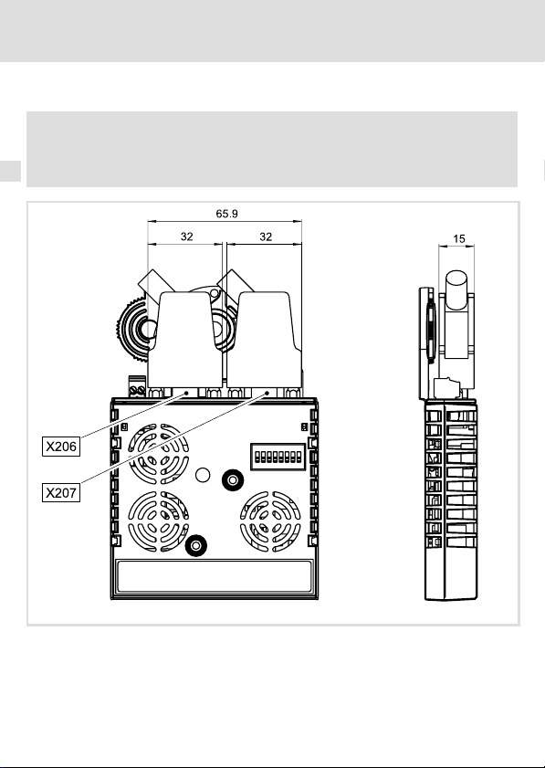
6 Instalación eléctrica
Dimensiones de los conectores Sub−D de 9 polos
Dimensiones de los conectores Sub−D de 9 polos
¡Aviso!
Respete las medidas de los conectores Sub−D de 9 polos para las conexiones
INTERBUS X206/X207.
90
E94YCIB001G
EDK94AYCIB DE/EN/FR/ES/IT 1.0
Page 91

Instalación eléctrica
Especificación de cables
Especificación de cables
Características generales
Tipo de cable Material por metro,
Número de conductores 3 × 2, trenzados a pares con apantallado conjunto
Sección de cable > 0.2 mm
Resistencia de cable DC
Impedancia (característica)
Capacidad lineica < 60 nF/km (f = 800 Hz)
Longitud del cable de bus
Adapte la velocidad de transmisión a la longitud del cable de bus:
Velocidad de transmisión Longitud de cable entre los distintos dispositivos conectados al
500 kBit/s 400 m
2 MBit/s 150 m
(p.e. PHOENIX CONTACT: IBS RBC Meter−T, ref. 28 06 28 6)
2
< 96 W/km
l 120 W ± 20 % (f = 64 kHz)
l 100 W ±15 W (f > 1 MHz)
INTERBUS
¡Aviso!
Elegir sólo la velocidad de transmisión que sea necesaria para la aplicación en
función de la cantidad de datos, el tiempo de ciclo y el número de usuarios.
6
EDK94AYCIB DE/EN/FR/ES/IT 1.0
91
Page 92

6 Instalación eléctrica
Voltaje de alimentación externo
Voltaje de alimentación externo
El módulo de comunicación se puede alimentar de forma externa a través de cables de
suministro separados por la regleta de bornes de 2 polos (X205).
¡Aviso!
En caso de que exista un voltaje de alimentación externo y que haya una gran
distancia entre los armarios de distribución, utilice en cada armario de
distribución una fuente de alimentación independiente y con separación
segura conforme a EN 61800−5−1 ("SELV"/"PELV").
ƒ El voltaje de alimentación externo del módulo de comunicación es necesario cuando
falla la alimentación del equipo básico pero debe mantenerse la comunicación a
través del bus.
ƒ El acceso a parámetros de un equipo básico no conectado a la red es imposible.
Asignación de la regleta de conectores X205
Regleta de
conectores
Conexión "+" U = 24VDC (21.6 V − 0% ... 26.4 V + 0 %)
Conexión "−" Potencial de referencia para suministro de voltaje externo
Datos de los bornes de conexión
Ámbito Valores
Conexión eléctrica Regleta de conectores de 2 polos con conexión por fuerza de resorte
Posibilidades de conexión
Longitud de aislamiento 10 mm
Explicación
I = 180 mA
rígido:
flexible:
0.2 ... 1.5 mm
sin terminal grimpado
0.2 ... 1.5 mm
con terminal grimpado, sin manguito de plástico
0.2 ... 1.5 mm
con terminal grimpado, con manguito de plástico
0.2 ... 1.5 mm
2
(AWG 24 ... 16)
2
(AWG 24 ... 16)
2
(AWG 24 ... 16)
2
(AWG 24 ... 16)
92
EDK94AYCIB DE/EN/FR/ES/IT 1.0
Page 93

Puesta en marcha
Antes de la primera conexión
7 Puesta en marcha
Antes de la primera conexión
¡Alto!
Antes de poner en marcha por primera vez el equipo básico con el módulo de
comunicación, compruebe que todo el cableado esté completo y que no haya
cortocircuitos ni contactos a tierra.
7
EDK94AYCIB DE/EN/FR/ES/IT 1.0
93
Page 94
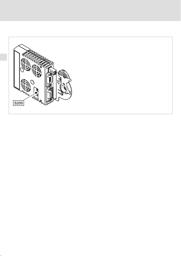
7 Puesta en marcha
Posibilidades de ajuste mediante el interruptor DIP
Posibilidades de ajuste mediante el interruptor DIP
A través del interruptor DIP (S205) se puede configurar:
ƒ el número de palabras de datos de proceso (PD) con los interruptores 1 ... 4
ƒ el número de palabras de datos de parámetros (PCP) con los interruptores 5 y 6
ƒ la velocidad de transmisión con el conector 8
Configuración Lenze: todos los interruptores en "OFF".
El interruptor DIP 7 no tiene ninguna función.
E94YCIB001D
94
EDK94AYCIB DE/EN/FR/ES/IT 1.0
Page 95

Posibilidades de ajuste mediante el interruptor DIP
¡Aviso!
Para activar las configuraciones modificadas desconecte el voltaje de
alimentación del módulo de comunicación y a continuación conéctelo de
nuevo.
Las configuraciones también se pueden realizar a través de códigos:
ƒ Todos los interruptores DIP = "OFF" (configuración Lenze):
Al conectar se activa la configuración de los códigos C13892/C14892,
C13893/C14893 y C13894/C14894.
ƒ Por lo menos un interruptor DIP = "ON":
Al conectar se asumen todos los valores de las posiciones de los
interruptores.
La suma de las palabras de datos (PD + PCP) no puede superar las 10 palabras.
Puesta en marcha
7
EDK94AYCIB DE/EN/FR/ES/IT 1.0
95
Page 96

7 Puesta en marcha
Posibilidades de ajuste mediante el interruptor DIP
Configurar el número de palabras de datos de proceso (PD)
ƒ El número de palabras de datos de proceso se puede configurar a través de los
interruptores del 1 al 4 o a través del código C13893 / C14893.
ƒ Se pueden utilizar de 0 a 10 palabras de datos de proceso.
ƒ La configuración actual se muestra en C13860/2 / C14860/2.
¡Aviso!
La suma de palabras de datos (PD + PCP) tiene que ser de 1 a 10 palabras. Las
configuraciones no permitidas se señalizan mediante el LED "BE" (parpadea
rojo,
99).
El módulo de comunicación seguirá trabajando entonces con los siguientes
valores:
ƒ PD = 2 (palabras)
ƒ PCP = 1 (palabra)
Interruptor DIP Número de PD
OFF
ON
12345678
96
Interruptor
0 OFF OFF OFF OFF
1 OFF OFF OFF ON
2 OFF OFF ON OFF
3 OFF OFF ON ON
4 OFF ON OFF OFF
5 OFF ON OFF ON
6 OFF ON ON OFF
7 OFF ON ON ON
8 ON OFF OFF OFF
9 ON OFF OFF ON 1
10 ON OFF ON OFF 0
1 2 3 4
EDK94AYCIB DE/EN/FR/ES/IT 1.0
Número máx.
de PCP
4
2
Page 97

Posibilidades de ajuste mediante el interruptor DIP
Configurar el número de palabras de datos de parámetros (PCP)
ƒ El número de palabras de datos de parámetros se puede configurar a través de los
interruptores 5 y 6 o a través del código C13892 / C14892.
ƒ Se pueden utilizar 0, 1, 2 o 4 palabras de datos de parámetros.
ƒ La configuración actual se muestra en C13860/1 / C14860/1.
¡Aviso!
La suma de palabras de datos (PD + PCP) tiene que ser de 1 a 10 palabras. Las
configuraciones no permitidas se señalizan mediante el LED "BE" (parpadea
rojo,
99).
El módulo de comunicación seguirá trabajando entonces con los siguientes
valores:
ƒ PD = 2 (palabras)
ƒ PCP = 1 (palabra)
Puesta en marcha
7
Interruptor DIP Número PCP
OFF
ON
12345678
EDK94AYCIB DE/EN/FR/ES/IT 1.0
Interruptor
5 6
0 OFF OFF 10 0x03
1 OFF ON 9 0xE3
2 ON OFF 8 0xE0
4 ON ON 6 0xE1
Número máx.
de PD
Código ID
[hex]
97
Page 98

7 Puesta en marcha
Posibilidades de ajuste mediante el interruptor DIP
Configurar la velocidad de transmisión
ƒ La velocidad de transmisión se puede configurar a través del interruptor 8 o a través
del código C13894 / C14894.
ƒ La configuración actual de la velocidad de transmisión se indica en C13863 / C14863.
Interruptor DIP Interruptor 8 Velocidad de
OFF
ON
12345678
OFF 500 kBit/s 400 m
ON 2 MBit/s 150 m
transmisión
Longitud máxima de cable entre dos
dispositivos seguidos
98
EDK94AYCIB DE/EN/FR/ES/IT 1.0
Page 99

Indicadores de estado LED
Diagnóstico
8 Diagnóstico
Indicadores de estado LED
E94YCIB001F
LED
Pos. Color Estado
MS verde parpadea El módulo de comunicación está siendo alimentado pero no tiene
MS verde encendido El módulo de comunicación está siendo alimentado y está
ME rojo encendido Hay un error en el área del módulo de comunicación.
BS verde
BE rojo
DE rojo encendido El módulo de comunicación no es aceptado por el equipo básico
apagado El módulo de comunicación no está activo en el bus de campo. No
parpadea Se ha establecido comunicación a través del módulo de
parpadea Configuración no permitida:
encendido Comunicación INTERBUS interrumpida. No se ejecutan ciclos de
Descripción
comunicación con el equipo básico. (El equipo básico está
desconectado, está en fase de inicialización o no está disponible.)
conectado al equipo básico.
se ejecutan ciclos de datos.
comunicación. El INTERBUS está activo. Se ejecutan ciclos de
datos.
l Suma de palabras de datos (PD + PCP) > 10
l Suma de palabras de datos (PD + PCP) = 0
El módulo de comunicación ha sido inicializado y sigue
trabajando de forma interna con los siguientes valores:
l PD = 2 (palabras)
l PCP = 1 (palabra)
datos.
(véanse las indicaciones en la documentación del equipo básico) o
el equipo básico no está activo.
8
EDK94AYCIB DE/EN/FR/ES/IT 1.0
99
Page 100

Legenda figura su pagina ripiegata
Pos. Descrizione Informazioni
S205 DIP switch per l’impostazione di
l numero di word di dati di processo e di word di parametri
l velocità di trasmissione
X205 Collegamento per alimentazione
l Morsettiera estraibile con collegamento a molla a 2 poli
X206 Collegamento INTERBUS, ingresso (IN)
l Connettore maschio Sub−D a 9 poli
X207 Collegamento INTERBUS, uscita (OUT)
l Connettore femmina Sub−D a 9 poli
MS
ME
BS
Indicatori di stato a LED per la diagnostica 123
BE
DE
0Fig. 0Tab. 0
dettagliate
118
116
112
100
EDK94AYCIB DE/EN/FR/ES/IT 1.0
 Loading...