

Page 1
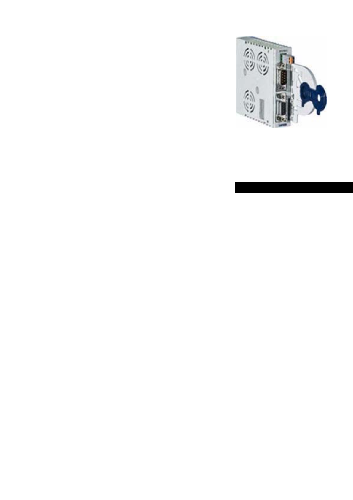
Accessories
INTERBUS
Servo Drives 9400
_ _ _ _ _ _ _ _ _ _ _ _ _ _ _ _ _ _ _ _ _ _ _ _ _ _
E94AYCIB
Communication Manual EN
Ä.N+øä
13451099
L
Page 2

Contents
_ _ _ _ _ _ _ _ _ _ _ _ _ _ _ _ _ _ _ _ _ _ _ _ _ _ _ _ _ _ _ _ _ _ _ _ _ _ _ _ _ _ _ _ _ _ _ _ _ _ _ _ _ _ _ _ _ _ _ _ _ _ _ _
1 About this documentation _ _ _ _ _ _ _ _ _ _ _ _ _ _ _ _ _ _ _ _ _ _ _ _ _ _ _ _ _ _ _ _ _ _ _ _ _ _ _ 4
1.1 Document history _ _ _ _ _ _ _ _ _ _ _ _ _ _ _ _ _ _ _ _ _ _ _ _ _ _ _ _ _ _ _ _ _ _ _ _ _ _ _ _ _ _ _ _ 6
1.2 Conventions used _ _ _ _ _ _ _ _ _ _ _ _ _ _ _ _ _ _ _ _ _ _ _ _ _ _ _ _ _ _ _ _ _ _ _ _ _ _ _ _ _ _ _ _ 7
1.3 Terminology used _ _ _ _ _ _ _ _ _ _ _ _ _ _ _ _ _ _ _ _ _ _ _ _ _ _ _ _ _ _ _ _ _ _ _ _ _ _ _ _ _ _ _ _ 8
1.4 Definition of the notes used _ _ _ _ _ _ _ _ _ _ _ _ _ _ _ _ _ _ _ _ _ _ _ _ _ _ _ _ _ _ _ _ _ _ _ _ _ _ 9
2Safety instructions _ _ _ _ _ _ _ _ _ _ _ _ _ _ _ _ _ _ _ _ _ _ _ _ _ _ _ _ _ _ _ _ _ _ _ _ _ _ _ _ _ _ _ _ 10
2.1 General safety and application notes _ _ _ _ _ _ _ _ _ _ _ _ _ _ _ _ _ _ _ _ _ _ _ _ _ _ _ _ _ _ _ _ _ 10
2.2 Device and application-specific safety instructions _ _ _ _ _ _ _ _ _ _ _ _ _ _ _ _ _ _ _ _ _ _ _ _ _ _ 11
2.3 Residual hazards _ _ _ _ _ _ _ _ _ _ _ _ _ _ _ _ _ _ _ _ _ _ _ _ _ _ _ _ _ _ _ _ _ _ _ _ _ _ _ _ _ _ _ _ _ 11
3 Product description _ _ _ _ _ _ _ _ _ _ _ _ _ _ _ _ _ _ _ _ _ _ _ _ _ _ _ _ _ _ _ _ _ _ _ _ _ _ _ _ _ _ _ 12
3.1 Application as directed _ _ _ _ _ _ _ _ _ _ _ _ _ _ _ _ _ _ _ _ _ _ _ _ _ _ _ _ _ _ _ _ _ _ _ _ _ _ _ _ _ 12
3.2 Identification _ _ _ _ _ _ _ _ _ _ _ _ _ _ _ _ _ _ _ _ _ _ _ _ _ _ _ _ _ _ _ _ _ _ _ _ _ _ _ _ _ _ _ _ _ _ _ 12
3.3 Product features _ _ _ _ _ _ _ _ _ _ _ _ _ _ _ _ _ _ _ _ _ _ _ _ _ _ _ _ _ _ _ _ _ _ _ _ _ _ _ _ _ _ _ _ _ 13
3.4 Terminals and interfaces _ _ _ _ _ _ _ _ _ _ _ _ _ _ _ _ _ _ _ _ _ _ _ _ _ _ _ _ _ _ _ _ _ _ _ _ _ _ _ _ 14
4 Technical data _ _ _ _ _ _ _ _ _ _ _ _ _ _ _ _ _ _ _ _ _ _ _ _ _ _ _ _ _ _ _ _ _ _ _ _ _ _ _ _ _ _ _ _ _ _ 15
4.1 General data and operating conditions _ _ _ _ _ _ _ _ _ _ _ _ _ _ _ _ _ _ _ _ _ _ _ _ _ _ _ _ _ _ _ _ 15
4.2 Protocol data _ _ _ _ _ _ _ _ _ _ _ _ _ _ _ _ _ _ _ _ _ _ _ _ _ _ _ _ _ _ _ _ _ _ _ _ _ _ _ _ _ _ _ _ _ _ _ 16
4.3 Communication time _ _ _ _ _ _ _ _ _ _ _ _ _ _ _ _ _ _ _ _ _ _ _ _ _ _ _ _ _ _ _ _ _ _ _ _ _ _ _ _ _ _ 16
4.4 Protective insulation _ _ _ _ _ _ _ _ _ _ _ _ _ _ _ _ _ _ _ _ _ _ _ _ _ _ _ _ _ _ _ _ _ _ _ _ _ _ _ _ _ _ 17
4.5 Dimensions _ _ _ _ _ _ _ _ _ _ _ _ _ _ _ _ _ _ _ _ _ _ _ _ _ _ _ _ _ _ _ _ _ _ _ _ _ _ _ _ _ _ _ _ _ _ _ 20
5Installation _ _ _ _ _ _ _ _ _ _ _ _ _ _ _ _ _ _ _ _ _ _ _ _ _ _ _ _ _ _ _ _ _ _ _ _ _ _ _ _ _ _ _ _ _ _ _ _ 21
5.1 Mechanical installation _ _ _ _ _ _ _ _ _ _ _ _ _ _ _ _ _ _ _ _ _ _ _ _ _ _ _ _ _ _ _ _ _ _ _ _ _ _ _ _ _ 22
5.1.1 Assembly _ _ _ _ _ _ _ _ _ _ _ _ _ _ _ _ _ _ _ _ _ _ _ _ _ _ _ _ _ _ _ _ _ _ _ _ _ _ _ _ _ _ _ _ 22
5.1.2 Disassembly _ _ _ _ _ _ _ _ _ _ _ _ _ _ _ _ _ _ _ _ _ _ _ _ _ _ _ _ _ _ _ _ _ _ _ _ _ _ _ _ _ _ 22
5.2 Electrical installation _ _ _ _ _ _ _ _ _ _ _ _ _ _ _ _ _ _ _ _ _ _ _ _ _ _ _ _ _ _ _ _ _ _ _ _ _ _ _ _ _ _ 23
5.2.1 Wiring according to EMC guidelines _ _ _ _ _ _ _ _ _ _ _ _ _ _ _ _ _ _ _ _ _ _ _ _ _ _ _ _ _ 23
5.2.2 Wiring of the INTERBUS _ _ _ _ _ _ _ _ _ _ _ _ _ _ _ _ _ _ _ _ _ _ _ _ _ _ _ _ _ _ _ _ _ _ _ _ 24
5.2.3 INTERBUS connection _ _ _ _ _ _ _ _ _ _ _ _ _ _ _ _ _ _ _ _ _ _ _ _ _ _ _ _ _ _ _ _ _ _ _ _ _ 25
5.2.4 Dimensions of 9-pole sub-D connectors _ _ _ _ _ _ _ _ _ _ _ _ _ _ _ _ _ _ _ _ _ _ _ _ _ _ _ 26
5.2.5 Bus cable specification _ _ _ _ _ _ _ _ _ _ _ _ _ _ _ _ _ _ _ _ _ _ _ _ _ _ _ _ _ _ _ _ _ _ _ _ _ 27
5.2.6 Bus cable length _ _ _ _ _ _ _ _ _ _ _ _ _ _ _ _ _ _ _ _ _ _ _ _ _ _ _ _ _ _ _ _ _ _ _ _ _ _ _ _ 27
5.2.7 External voltage supply _ _ _ _ _ _ _ _ _ _ _ _ _ _ _ _ _ _ _ _ _ _ _ _ _ _ _ _ _ _ _ _ _ _ _ _ 28
6 Commissioning _ _ _ _ _ _ _ _ _ _ _ _ _ _ _ _ _ _ _ _ _ _ _ _ _ _ _ _ _ _ _ _ _ _ _ _ _ _ _ _ _ _ _ _ _ 29
6.1 Before initial switch-on _ _ _ _ _ _ _ _ _ _ _ _ _ _ _ _ _ _ _ _ _ _ _ _ _ _ _ _ _ _ _ _ _ _ _ _ _ _ _ _ _ 29
6.2 Possible settings via DIP switch _ _ _ _ _ _ _ _ _ _ _ _ _ _ _ _ _ _ _ _ _ _ _ _ _ _ _ _ _ _ _ _ _ _ _ _ _ 30
6.2.1 Setting the number of process data words _ _ _ _ _ _ _ _ _ _ _ _ _ _ _ _ _ _ _ _ _ _ _ _ _ _ 31
6.2.2 Setting the number of parameter data words _ _ _ _ _ _ _ _ _ _ _ _ _ _ _ _ _ _ _ _ _ _ _ _ 32
6.2.3 Setting the baud rate _ _ _ _ _ _ _ _ _ _ _ _ _ _ _ _ _ _ _ _ _ _ _ _ _ _ _ _ _ _ _ _ _ _ _ _ _ 33
6.3 Settings in »Engineer« _ _ _ _ _ _ _ _ _ _ _ _ _ _ _ _ _ _ _ _ _ _ _ _ _ _ _ _ _ _ _ _ _ _ _ _ _ _ _ _ _ _ 34
6.4 Initial switch-on _ _ _ _ _ _ _ _ _ _ _ _ _ _ _ _ _ _ _ _ _ _ _ _ _ _ _ _ _ _ _ _ _ _ _ _ _ _ _ _ _ _ _ _ _ 35
2 Lenze · E94AYCIB communication module (INTERBUS) · Communication Manual · DMS 4.0 EN · 02/2014 · TD17
Page 3

Contents
_ _ _ _ _ _ _ _ _ _ _ _ _ _ _ _ _ _ _ _ _ _ _ _ _ _ _ _ _ _ _ _ _ _ _ _ _ _ _ _ _ _ _ _ _ _ _ _ _ _ _ _ _ _ _ _ _ _ _ _ _ _ _ _
7 Data transfer _ _ _ _ _ _ _ _ _ _ _ _ _ _ _ _ _ _ _ _ _ _ _ _ _ _ _ _ _ _ _ _ _ _ _ _ _ _ _ _ _ _ _ _ _ _ _ 36
8 Process data transfer _ _ _ _ _ _ _ _ _ _ _ _ _ _ _ _ _ _ _ _ _ _ _ _ _ _ _ _ _ _ _ _ _ _ _ _ _ _ _ _ _ _ 37
9 Parameter data transfer _ _ _ _ _ _ _ _ _ _ _ _ _ _ _ _ _ _ _ _ _ _ _ _ _ _ _ _ _ _ _ _ _ _ _ _ _ _ _ _ _ 39
9.1 Addressing of the parameter data _ _ _ _ _ _ _ _ _ _ _ _ _ _ _ _ _ _ _ _ _ _ _ _ _ _ _ _ _ _ _ _ _ _ _ 39
9.2 Initialising PCP communication _ _ _ _ _ _ _ _ _ _ _ _ _ _ _ _ _ _ _ _ _ _ _ _ _ _ _ _ _ _ _ _ _ _ _ _ _ 40
9.3 Supported PMS services _ _ _ _ _ _ _ _ _ _ _ _ _ _ _ _ _ _ _ _ _ _ _ _ _ _ _ _ _ _ _ _ _ _ _ _ _ _ _ _ _ 41
9.3.1 Initiate _ _ _ _ _ _ _ _ _ _ _ _ _ _ _ _ _ _ _ _ _ _ _ _ _ _ _ _ _ _ _ _ _ _ _ _ _ _ _ _ _ _ _ _ _ 41
9.3.2 Abort _ _ _ _ _ _ _ _ _ _ _ _ _ _ _ _ _ _ _ _ _ _ _ _ _ _ _ _ _ _ _ _ _ _ _ _ _ _ _ _ _ _ _ _ _ _ 41
9.3.3 Reject _ _ _ _ _ _ _ _ _ _ _ _ _ _ _ _ _ _ _ _ _ _ _ _ _ _ _ _ _ _ _ _ _ _ _ _ _ _ _ _ _ _ _ _ _ _ 41
9.3.4 Read/Write _ _ _ _ _ _ _ _ _ _ _ _ _ _ _ _ _ _ _ _ _ _ _ _ _ _ _ _ _ _ _ _ _ _ _ _ _ _ _ _ _ _ _ 42
9.3.5 Get-OD _ _ _ _ _ _ _ _ _ _ _ _ _ _ _ _ _ _ _ _ _ _ _ _ _ _ _ _ _ _ _ _ _ _ _ _ _ _ _ _ _ _ _ _ _ 42
9.3.6 Identify _ _ _ _ _ _ _ _ _ _ _ _ _ _ _ _ _ _ _ _ _ _ _ _ _ _ _ _ _ _ _ _ _ _ _ _ _ _ _ _ _ _ _ _ _ 43
9.3.7 Status _ _ _ _ _ _ _ _ _ _ _ _ _ _ _ _ _ _ _ _ _ _ _ _ _ _ _ _ _ _ _ _ _ _ _ _ _ _ _ _ _ _ _ _ _ _ 44
10 Monitoring _ _ _ _ _ _ _ _ _ _ _ _ _ _ _ _ _ _ _ _ _ _ _ _ _ _ _ _ _ _ _ _ _ _ _ _ _ _ _ _ _ _ _ _ _ _ _ _ 45
10.1 Interruption of the INTERBUS communication _ _ _ _ _ _ _ _ _ _ _ _ _ _ _ _ _ _ _ _ _ _ _ _ _ _ _ _ 45
10.2 Interruption of internal communication _ _ _ _ _ _ _ _ _ _ _ _ _ _ _ _ _ _ _ _ _ _ _ _ _ _ _ _ _ _ _ _ 46
11 Diagnostics _ _ _ _ _ _ _ _ _ _ _ _ _ _ _ _ _ _ _ _ _ _ _ _ _ _ _ _ _ _ _ _ _ _ _ _ _ _ _ _ _ _ _ _ _ _ _ _ 47
11.1 LED status displays _ _ _ _ _ _ _ _ _ _ _ _ _ _ _ _ _ _ _ _ _ _ _ _ _ _ _ _ _ _ _ _ _ _ _ _ _ _ _ _ _ _ _ 47
11.2 Diagnosing with the »Engineer« _ _ _ _ _ _ _ _ _ _ _ _ _ _ _ _ _ _ _ _ _ _ _ _ _ _ _ _ _ _ _ _ _ _ _ _ 48
12 Error messages _ _ _ _ _ _ _ _ _ _ _ _ _ _ _ _ _ _ _ _ _ _ _ _ _ _ _ _ _ _ _ _ _ _ _ _ _ _ _ _ _ _ _ _ _ _ 49
12.1 Short overview of the INTERBUS error messages _ _ _ _ _ _ _ _ _ _ _ _ _ _ _ _ _ _ _ _ _ _ _ _ _ _ _ 49
12.2 Possible causes and remedies _ _ _ _ _ _ _ _ _ _ _ _ _ _ _ _ _ _ _ _ _ _ _ _ _ _ _ _ _ _ _ _ _ _ _ _ _ _ 50
13 Parameter reference _ _ _ _ _ _ _ _ _ _ _ _ _ _ _ _ _ _ _ _ _ _ _ _ _ _ _ _ _ _ _ _ _ _ _ _ _ _ _ _ _ _ _ 53
13.1 Parameters of the standard device that are relevant to communication _ _ _ _ _ _ _ _ _ _ _ _ _ _ 53
13.2 Parameters of the communication module for slot MXI1 _ _ _ _ _ _ _ _ _ _ _ _ _ _ _ _ _ _ _ _ _ _ _ 55
13.3 Parameters of the communication module for slot MXI2 _ _ _ _ _ _ _ _ _ _ _ _ _ _ _ _ _ _ _ _ _ _ _ 63
13.4 Table of attributes _ _ _ _ _ _ _ _ _ _ _ _ _ _ _ _ _ _ _ _ _ _ _ _ _ _ _ _ _ _ _ _ _ _ _ _ _ _ _ _ _ _ _ _ 71
14 Index _ _ _ _ _ _ _ _ _ _ _ _ _ _ _ _ _ _ _ _ _ _ _ _ _ _ _ _ _ _ _ _ _ _ _ _ _ _ _ _ _ _ _ _ _ _ _ _ _ _ _ 74
Your opinion is important to us _ _ _ _ _ _ _ _ _ _ _ _ _ _ _ _ _ _ _ _ _ _ _ _ _ _ _ _ _ _ _ _ _ _ _ _ _ 77
Lenze · E94AYCIB communication module (INTERBUS) · Communication Manual · DMS 4.0 EN · 02/2014 · TD17 3
Page 4

1 About this documentation
_ _ _ _ _ _ _ _ _ _ _ _ _ _ _ _ _ _ _ _ _ _ _ _ _ _ _ _ _ _ _ _ _ _ _ _ _ _ _ _ _ _ _ _ _ _ _ _ _ _ _ _ _ _ _ _ _ _ _ _ _ _ _ _
1 About this documentation
This documentation exclusively describes the E94AYCIB communication module (INTERBUS).
Note!
This documentation supplements the mounting instructions supplied with the
communication module and the Servo Drives 9400 hardware manual.
The mounting instructions contain safety instructions which must be observed!
The features and functions of the communication module are described in detail.
Examples illustrate typical applications.
The theoretical context is only explained as far as it is required for understanding the function of
the communication module.
This documentation does not describe any software provided by other manufacturers. No warranty
can be given for corresponding data provided in this documentation. For information on how to use
the software, please refer to the host (PLC, master) documents.
All brand names mentioned in this documentation are trademarks of their corresponding owners.
Tip!
More information on the INTERBUS can be found on this internet page:
www.interbus.com
Maintenance activities for the INTERBUS technologies are carried out by the user
organisation PROFIBUS & PROFINET International (PI).
www.profibus.com
4 Lenze · E94AYCIB communication module (INTERBUS) · Communication Manual · DMS 4.0 EN · 02/2014 · TD17
Page 5

1 About this documentation
_ _ _ _ _ _ _ _ _ _ _ _ _ _ _ _ _ _ _ _ _ _ _ _ _ _ _ _ _ _ _ _ _ _ _ _ _ _ _ _ _ _ _ _ _ _ _ _ _ _ _ _ _ _ _ _ _ _ _ _ _ _ _ _
Target group
This documentation is intended for all persons who plan, install, commission and maintain the
networking and remote servicing of a machine.
Tip!
Current documentation and software updates with regard to Lenze products can be found
in the download area at:
www.lenze.com
Information regarding the validity
The information given in this documentation is valid for the following devices:
Extension module Type designation From hardware
version
Communication module INTERBUS E94AYCIB PA 01.00
Screenshots/application examples
All screenshots in this documentation are application examples. Depending on the firmware
version of the communication module and the software version of the engineering tools installed
(e.g. »Engineer«), the screenshots in this documentation may differ from the actual screen
representation.
From software
version
Lenze · E94AYCIB communication module (INTERBUS) · Communication Manual · DMS 4.0 EN · 02/2014 · TD17 5
Page 6

1 About this documentation
1.1 Document history
_ _ _ _ _ _ _ _ _ _ _ _ _ _ _ _ _ _ _ _ _ _ _ _ _ _ _ _ _ _ _ _ _ _ _ _ _ _ _ _ _ _ _ _ _ _ _ _ _ _ _ _ _ _ _ _ _ _ _ _ _ _ _ _
1.1 Document history
Version Description
1.0 03/2009 TD17 Field test version
2.0 06/2009 TD17 General revision
3.0 11/2009 TD17 General revision
4.0 02/2014 TD17 • New layout
• General updates
6
Lenze · E94AYCIB communication module (INTERBUS) · Communication Manual · DMS 4.0 EN · 02/2014 · TD17
Page 7

1 About this documentation
1.2 Conventions used
_ _ _ _ _ _ _ _ _ _ _ _ _ _ _ _ _ _ _ _ _ _ _ _ _ _ _ _ _ _ _ _ _ _ _ _ _ _ _ _ _ _ _ _ _ _ _ _ _ _ _ _ _ _ _ _ _ _ _ _ _ _ _ _
1.2 Conventions used
This documentation uses the following conventions to distinguish between different types of
information:
Type of information Writing Examples/notes
Spelling of numbers
Decimal Normal spelling Example: 1234
Decimal separator Point The decimal point is always used.
For example: 1234.56
Hexadecimal 0x[0 ... 9, A ... F] Example: 0x60F4
Binary
• Nibble
Text
Version information Blue text colour All information that applies to from a certain software
Program name » « The Lenze PC software »Engineer«...
Control element bold The OK button ... / The Copy command ... / The Properties tab
Sequence of menu
commands
Hyperlink Underlined
Icons
Page reference ( 8) Optically highlighted reference to another page. In this
Step-by-step instructions
In inverted commas
Point
Example: ’100’
Example: ’0110.0100’
version of the device onwards are marked accordingly in this
documentation.
Example: This function extension is available from software
version V3.0 onwards!
... / The Name input field ...
If several commands are required to execute one function,
the single commands are separated by an arrow: Select the
Open command to...
File
Optically highlighted reference to another topic. It is
activated with a mouse-click in this online documentation.
online documentation activated via mouse-click.
Step-by-step instructions are indicated by a pictograph.
Lenze · E94AYCIB communication module (INTERBUS) · Communication Manual · DMS 4.0 EN · 02/2014 · TD17 7
Page 8
1 About this documentation
1.3 Terminology used
_ _ _ _ _ _ _ _ _ _ _ _ _ _ _ _ _ _ _ _ _ _ _ _ _ _ _ _ _ _ _ _ _ _ _ _ _ _ _ _ _ _ _ _ _ _ _ _ _ _ _ _ _ _ _ _ _ _ _ _ _ _ _ _
1.3 Terminology used
Term Meaning
Drive Lenze inverter of the "Servo Drives 9400" product series, with which the
Inverter
Standard device
Code Parameter which serves to parameterise and monitor the drive. In normal usage,
Subcode If a code contains several parameters, they are stored in "subcodes".
»Engineer« Lenze PC software which supports you during the "Engineering" process
communication module can be used.
Application as directed
the term is usually referred to as "Index".
In the documentation, the slash "/" is used as a separator between the code and
the subcode (e.g. "C00118/3").
In everyday language, the term is also referred to as "subindex".
(parameterisation, diagnostics, and configuration) throughout the whole life
cycle, i. e. from planning to maintenance of the machine commissioned.
INTERBUS was developed as sensor/actuator bus system for transmitting
process data.
Maintenance activities for the INTERBUS technologies are carried out by the user
organisation PROFIBUS & PROFINET International (PI).
( 12)
Host PLC, INTERBUS master
PCP Peripherials Communication Protocol for transmitting parameter data
PDO Process data object
PDU Process Data Unit
PMS Peripheral Message Specification
HW Hardware
SW Software
8
Lenze · E94AYCIB communication module (INTERBUS) · Communication Manual · DMS 4.0 EN · 02/2014 · TD17
Page 9

1 About this documentation
1.4 Definition of the notes used
_ _ _ _ _ _ _ _ _ _ _ _ _ _ _ _ _ _ _ _ _ _ _ _ _ _ _ _ _ _ _ _ _ _ _ _ _ _ _ _ _ _ _ _ _ _ _ _ _ _ _ _ _ _ _ _ _ _ _ _ _ _ _ _
1.4 Definition of the notes used
The following signal words and symbols are used in this documentation to indicate dangers and
important information:
Safety instructions
Layout of the safety instructions:
Danger!
(characterises the type and severity of danger)
Note
(describes the danger and gives information about how to prevent dangerous
situations)
Pictograph Signal word Meaning
Danger! Danger of personal injury through dangerous electrical voltage
Danger! Danger of personal injury through a general source of danger
Stop! Danger of property damage
Application notes
Pictograph Signal word Meaning
Note! Important note to ensure trouble-free operation
Reference to an imminent danger that may result in death or serious personal
injury if the corresponding measures are not taken.
Reference to an imminent danger that may result in death or serious personal
injury if the corresponding measures are not taken.
Reference to a possible danger that may result in property damage if the
corresponding measures are not taken.
Tip! Useful tip for easy handling
Reference to another document
Lenze · E94AYCIB communication module (INTERBUS) · Communication Manual · DMS 4.0 EN · 02/2014 · TD17 9
Page 10

2 Safety instructions
2.1 General safety and application notes
_ _ _ _ _ _ _ _ _ _ _ _ _ _ _ _ _ _ _ _ _ _ _ _ _ _ _ _ _ _ _ _ _ _ _ _ _ _ _ _ _ _ _ _ _ _ _ _ _ _ _ _ _ _ _ _ _ _ _ _ _ _ _ _
2 Safety instructions
Note!
It is absolutely vital that the stated safety measures are implemented in order to prevent
serious injury to persons and damage to material assets.
Always keep this documentation to hand in the vicinity of the product during operation.
2.1 General safety and application notes
Danger!
If the following basic safety measures are disregarded, severe injuries to persons and
damage to material assets may result.
Lenze drive and automation components ...
• must only be used as directed.
Application as directed
• must never be commissioned if they display signs of damage.
• must never be technically modified.
( 12)
• must never be commissioned if they are not fully mounted.
• must never be operated without required covers.
• during and after operation can have live, moving and rotating parts, depending on their degree
of protection. Surfaces can be hot.
The following applies to Lenze drive components ...
• only use the accessories approved.
• Only use original manufacturer spare parts.
Observe all specifications contained in the enclosed documentation and related documentation.
• This is the precondition for safe and trouble-free operation and for obtaining the product
features specified.
Product features
• The specifications, processes, and circuitry described in this document are for guidance only and
must be adapted to your own specific application. Lenze does not take responsibility for the
suitability of the process and circuit proposals.
( 13)
10
All works on and with Lenze drive and automation components must only be carried out by qualified
personnel. According to IEC 60364 or CENELEC HD 384 these are persons who ...
• are familiar with installing, mounting, commissioning, and operating the product.
• who have the corresponding qualifications for their work.
• who know and can apply all regulations for the prevention of accidents, directives, and laws
applicable at the place of use.
Lenze · E94AYCIB communication module (INTERBUS) · Communication Manual · DMS 4.0 EN · 02/2014 · TD17
Page 11

2 Safety instructions
2.2 Device and application-specific safety instructions
_ _ _ _ _ _ _ _ _ _ _ _ _ _ _ _ _ _ _ _ _ _ _ _ _ _ _ _ _ _ _ _ _ _ _ _ _ _ _ _ _ _ _ _ _ _ _ _ _ _ _ _ _ _ _ _ _ _ _ _ _ _ _ _
2.2 Device and application-specific safety instructions
• During operation, the communication module must be securely connected to the standard
device.
• With external voltage supply, always use a separate power supply unit, safely separated to
EN 61800-5-1 in every control cabinet (SELV/PELV).
• Only use cables corresponding to the given specifications.
Bus cable specification
( 27)
Documentation for the standard device, host (PLC, master), system/machine
All the other measures prescribed in this documentation must also be implemented.
Observe the safety instructions and application notes contained in this manual.
2.3 Residual hazards
Protection of persons
If Servo Drives 9400 are used on a phase earthed mains with a rated mains voltage 400 V,
protection against accidental contact is not guaranteed without external measures.
Protective insulation
Device protection
The communication module contains electronic components which may be damaged or destroyed
by electrostatic discharge.
Installation
( 21)
( 17)
Lenze · E94AYCIB communication module (INTERBUS) · Communication Manual · DMS 4.0 EN · 02/2014 · TD17 11
Page 12
3 Product description
3.1 Application as directed
_ _ _ _ _ _ _ _ _ _ _ _ _ _ _ _ _ _ _ _ _ _ _ _ _ _ _ _ _ _ _ _ _ _ _ _ _ _ _ _ _ _ _ _ _ _ _ _ _ _ _ _ _ _ _ _ _ _ _ _ _ _ _ _
3 Product description
3.1 Application as directed
The communication module ...
• is an accessory module that can be used in conjunction with the following standard devices:
Product series Type designation From hardware
Servo Drives 9400 HighLine E94AxHExxx 1A 03.00
Servo Drives 9400 PLC E94AxPExxxx VA 02.00
Regenerative power supply module E94ARNxxxx VA 01.00
• is a device intended for use in industrial power systems.
• should only be used under the operating conditions prescribed in this documentation.
• can only be used in INTERBUS networks.
Any other use shall be deemed inappropriate!
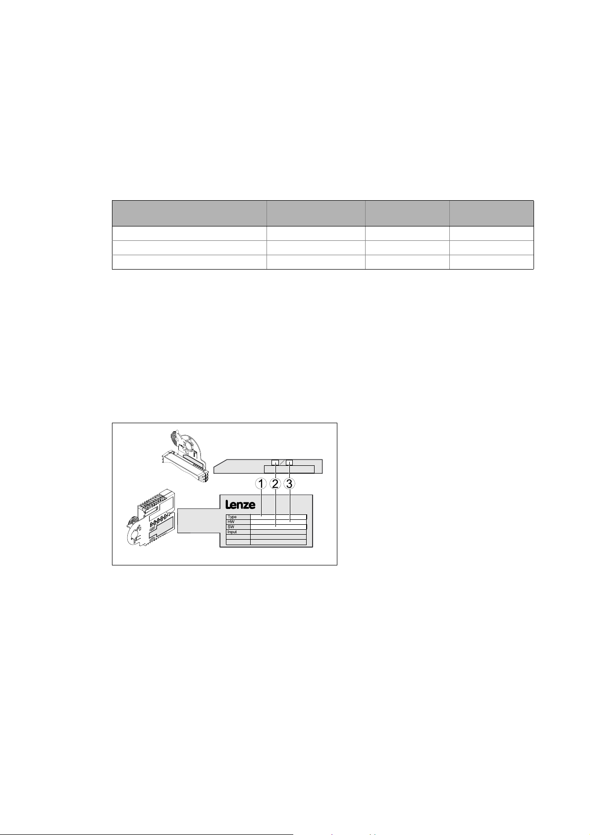
3.2 Identification
The type designation and hardware and software version of the communication module are
specified on the nameplate:
[3-1] Identification data
E94YCIB005
version
1 Type designation (type)
E94 Product series
AVersion
Y Module identification: Extension module
C Module type: Communication module
IB INTERBUS
2 Hardware version (HW)
3 Software version (SW)
From software
version
12
Lenze · E94AYCIB communication module (INTERBUS) · Communication Manual · DMS 4.0 EN · 02/2014 · TD17
Page 13

3 Product description
3.3 Product features
_ _ _ _ _ _ _ _ _ _ _ _ _ _ _ _ _ _ _ _ _ _ _ _ _ _ _ _ _ _ _ _ _ _ _ _ _ _ _ _ _ _ _ _ _ _ _ _ _ _ _ _ _ _ _ _ _ _ _ _ _ _ _ _
3.3 Product features
• Interface module for the INTERBUS communication system to be connected to the expansion
slots of the Servo Drives 9400
• The communication module can either be supplied internally by the standard device or
externally by a separate voltage source.
• Slave functionality
• DIP switch settings:
• Number of process data words and parameter data words
• Baud rate (500 kbps or 2 Mbps)
• Bus coupling via remote bus according to the RS485 standard
• Up to 10 process data words (20 bytes) can be used.
• 0, 1, 2 order 4 parameter data words can be used.
• The parameter data is transmitted in accordance with the Peripherials Communication Protocol
(PCP).
• Access to all Lenze parameters
• Support of the PMS services:
•Initiate
•Abort
• Reject
•Read
•Write
•Get-OD
•Identify
• Status
Lenze · E94AYCIB communication module (INTERBUS) · Communication Manual · DMS 4.0 EN · 02/2014 · TD17 13
Page 14
3 Product description
3.4 Terminals and interfaces
_ _ _ _ _ _ _ _ _ _ _ _ _ _ _ _ _ _ _ _ _ _ _ _ _ _ _ _ _ _ _ _ _ _ _ _ _ _ _ _ _ _ _ _ _ _ _ _ _ _ _ _ _ _ _ _ _ _ _ _ _ _ _ _
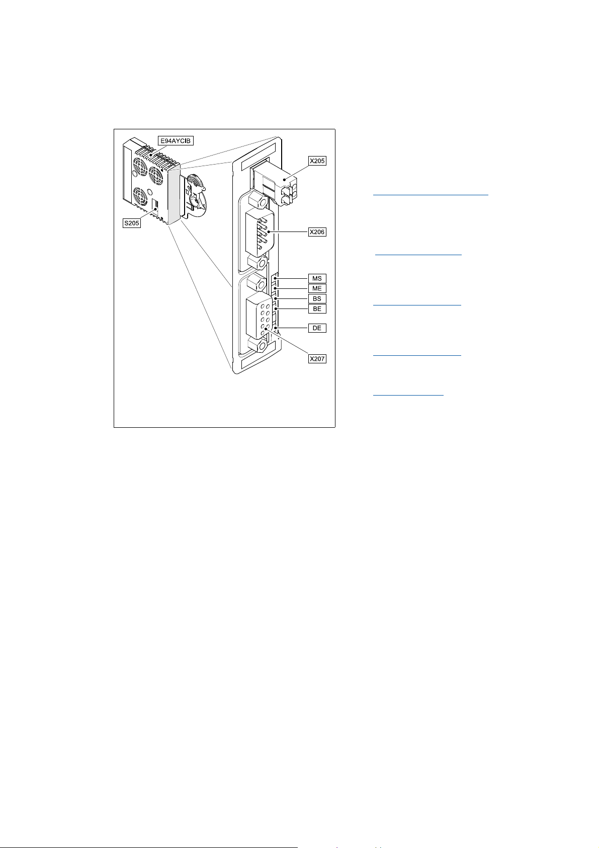
3.4 Terminals and interfaces
S205 DIP switches for setting the ...
• Number of process data words and
parameter data words
•Baud rate
Possible settings via DIP switch
X205 External voltage supply of the communication
module
• 2-pin plug connector with spring connection
External voltage supply
X206 INTERBUS connection, input (IN)
• 9-pole Sub-D plug
Wiring of the INTERBUS
( 30)
( 28)
( 24)
X207 INTERBUS connection, output (OUT)
• 9-pin Sub-D socket
Wiring of the INTERBUS
MS
E94YCIB001B
[3-2] E94AYCIB communication module (INTERBUS)
LED status displays for diagnostic purposes
ME
LED status displays
BS
BE
DE
( 24)
( 47)
14
Lenze · E94AYCIB communication module (INTERBUS) · Communication Manual · DMS 4.0 EN · 02/2014 · TD17
Page 15

4Technical data
4.1 General data and operating conditions
_ _ _ _ _ _ _ _ _ _ _ _ _ _ _ _ _ _ _ _ _ _ _ _ _ _ _ _ _ _ _ _ _ _ _ _ _ _ _ _ _ _ _ _ _ _ _ _ _ _ _ _ _ _ _ _ _ _ _ _ _ _ _ _
4 Technical data
4.1 General data and operating conditions
Range Values
Order designation E94AYCIB
Communication profile INTERBUS
Communication medium RS485
Interface for communication • Input (IN): 9-pole Sub-D plug
• Output (OUT): 9-pole Sub-D socket
Network topology Ring
Type of node Slave
Number of nodes • 1 master
• 512 slaves
Baud rate 500 kbps or 2 Mbps
(can be set via DIP switch or code)
Max. cable length • 400 m at 500 kbps
• 150 m at 2 Mbps
(between the single INTERBUS nodes)
Process data words 0 ... 10 words (16 bits/word)
(can be set via DIP switch or code)
Parameter data words 0, 1, 2, 4 words (16 bits/word)
(can be set via DIP switch or code)
The parameter data is transmitted in accordance with the Peripherials
Communication Protocol (PCP).
Max. number of data words 10 words (process data word + parameter data words), 16 bits/word
Max. PDU length 64 bytes
Device identification (module ID) • 3 = 0x03 (0 parameter data words)
• 227 = 0xE3 (1 parameter data words)
• 224 = 0xE0 (2 parameter data words)
• 225 = 0xE1 (4 parameter data words)
Voltage supply External supply via separate power supply unit
+: U = 24 V DC (+/- 10 %), I
- : Reference potential for external voltage supply
Conformities, approvals • CE
•UL
(see also hardware manual)
= 180 mA
max
Servo Drives 9400 hardware manual
Here you can find the ambient conditions and information on the electromagnetic
compatibility (EMC) which also apply to the communication module.
Lenze · E94AYCIB communication module (INTERBUS) · Communication Manual · DMS 4.0 EN · 02/2014 · TD17 15
Page 16

4Technical data
4.2 Protocol data
_ _ _ _ _ _ _ _ _ _ _ _ _ _ _ _ _ _ _ _ _ _ _ _ _ _ _ _ _ _ _ _ _ _ _ _ _ _ _ _ _ _ _ _ _ _ _ _ _ _ _ _ _ _ _ _ _ _ _ _ _ _ _ _
4.2 Protocol data
Range Values
Process data words 0 ... 10 words (16 bits/word)
Parameter data words 0, 1, 2, 4 words (16 bits/word)
The parameter data is transmitted in accordance with the Peripherials
Communication Protocol (PCP).
Supported PMS services • Initiate
•Abort
• Reject
•Read
•Write
•Get-OD
•Identify
• Status
Note!
The data word sum (process data words + parameter data words) has to consist of 1 ... 10
words (16 bits/word).
4.3 Communication time
The communication time is the time between the start of a request and the arrival of the
corresponding response.
The communication times in an INTERBUS network depend on the ...
• processing time in the inverter;
• telegram runtime (baud rate / telegram length);
• nesting depth of the network.
processing time within the inverter
Data Processing time
Process data Approx. 4 ms
Parameter data Approx. 30 ms + a tolerance of 20 ms (typically)
Update cycle
+ 0 ... 1 ms
+ 1 ... x ms
Some codes may require a longer processing time (see reference manual/
»Engineer« online help for the Servo Drive 9400).
Processing time in the module
Runtime of the application task of the technology
application used (tolerance)
16
There are no interdependencies between parameter data and process data.
Lenze · E94AYCIB communication module (INTERBUS) · Communication Manual · DMS 4.0 EN · 02/2014 · TD17
Page 17

4Technical data
4.4 Protective insulation
_ _ _ _ _ _ _ _ _ _ _ _ _ _ _ _ _ _ _ _ _ _ _ _ _ _ _ _ _ _ _ _ _ _ _ _ _ _ _ _ _ _ _ _ _ _ _ _ _ _ _ _ _ _ _ _ _ _ _ _ _ _ _ _
4.4 Protective insulation
Danger!
Dangerous voltage
If the Servo Drives 9400 are operated on a phase earthed mains with a rated mains
voltage 400 V, external measures need to be implemented in order to ensure
protection against accidental contact.
Possible consequences:
Death or severe injuries
Protective measures:
If protection against accidental contact is required for the control terminals of the
inverter and the connections of the plugged device modules, ...
• a double isolating distance must exist.
• the components to be connected must be provided with the second isolating
distance.
Note!
The protective insulation provided in Servo Drives 9400 is implemented in accordance
with EN 61800-5-1.
Lenze · E94AYCIB communication module (INTERBUS) · Communication Manual · DMS 4.0 EN · 02/2014 · TD17 17
Page 18
4Technical data
Ext. DC
I/O
X4
X6X6
X5
X7X7
X8X8
X3
X2
X1
X105X105
X106
X100
X107
MXI1
MXI2
Bus
Ext. DC
MSI
MMI
X207
X206
X205
4.4 Protective insulation
_ _ _ _ _ _ _ _ _ _ _ _ _ _ _ _ _ _ _ _ _ _ _ _ _ _ _ _ _ _ _ _ _ _ _ _ _ _ _ _ _ _ _ _ _ _ _ _ _ _ _ _ _ _ _ _ _ _ _ _ _ _ _ _
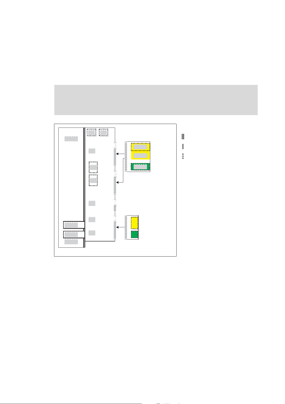
The following illustration ...
• shows the arrangement of the terminal strips and the separate potential areas of the Servo
Drive 9400.
• serves to determine the decisive protective insulation between two terminals located in
differently insulated separate potential areas.
Note!
The INTERBUS input (X206) is isolated from the voltage supply (X205) and the INTERBUS
output (X207).
Reinforced insulation
Basic insulation
Functional insulation
E94YCIB007
[4-1] Protective insulation in accordance with EN61800-5-1
18
Lenze · E94AYCIB communication module (INTERBUS) · Communication Manual · DMS 4.0 EN · 02/2014 · TD17
Page 19

4Technical data
4.4 Protective insulation
_ _ _ _ _ _ _ _ _ _ _ _ _ _ _ _ _ _ _ _ _ _ _ _ _ _ _ _ _ _ _ _ _ _ _ _ _ _ _ _ _ _ _ _ _ _ _ _ _ _ _ _ _ _ _ _ _ _ _ _ _ _ _ _
Terminal strip Connection Terminal strip Connection
X100 L1, L2, L3 (Single Drive only) X1 CAN on board 9400
+UG, -UG X2 State bus
X105 U, V, W 24 V (ext.)
Rb1, Rb2 (Single Drive only) X3 Analog inputs/outputs
X106 Motor PTC X4 Digital outputs
X107 Control of the motor holding
brake
MXI1, MXI2 Extension module
X5 Digital inputs
X6 Diagnostics
X7 Resolver
X8 Encoder
MMI Memory module
MSI Safety module
X205 External voltage supply (24 V DC)
X206 INTERBUS connection, input (IN)
X207 INTERBUS connection, output
(OUT)
Example
Which type of protective insulation is used between the bus terminal of the device module in slot
MXI1 or MXI2 and the mains terminal X100?
The separate potential area with the better protective insulation is decisive.
• The separate potential area of the bus terminal of the device module has a "functional
insulation".
• The separate potential area of the mains terminal has a "reinforced insulation".
Result: The insulation between mains terminal X100 and the bus terminal is of the "reinforced
insulation" type.
Lenze · E94AYCIB communication module (INTERBUS) · Communication Manual · DMS 4.0 EN · 02/2014 · TD17 19
Page 20
4Technical data
4.5 Dimensions
_ _ _ _ _ _ _ _ _ _ _ _ _ _ _ _ _ _ _ _ _ _ _ _ _ _ _ _ _ _ _ _ _ _ _ _ _ _ _ _ _ _ _ _ _ _ _ _ _ _ _ _ _ _ _ _ _ _ _ _ _ _ _ _
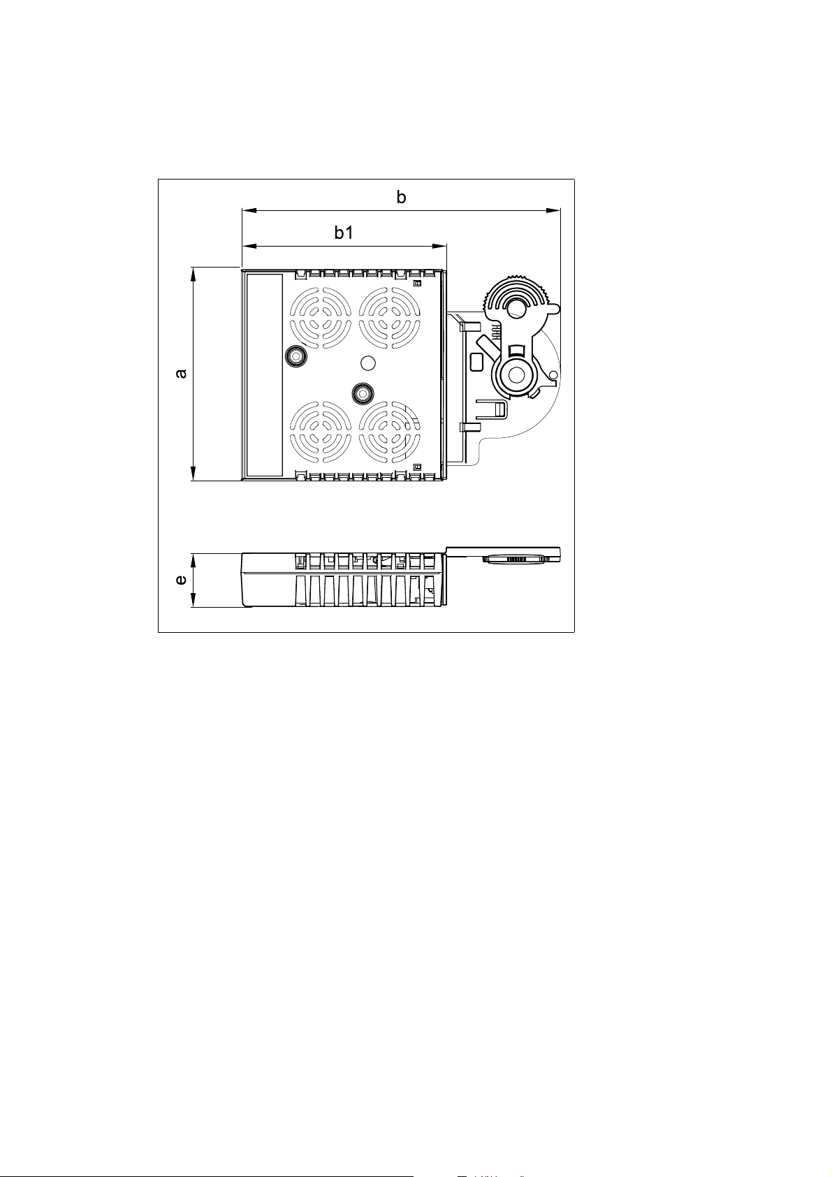
4.5 Dimensions
a 89 mm
b 134 mm
b1 87 mm
e 23 mm
E94YCXX005
[4-2] Dimensions
20
Lenze · E94AYCIB communication module (INTERBUS) · Communication Manual · DMS 4.0 EN · 02/2014 · TD17
Page 21

5 Installation
_ _ _ _ _ _ _ _ _ _ _ _ _ _ _ _ _ _ _ _ _ _ _ _ _ _ _ _ _ _ _ _ _ _ _ _ _ _ _ _ _ _ _ _ _ _ _ _ _ _ _ _ _ _ _ _ _ _ _ _ _ _ _ _
5 Installation
Stop!
Electrostatic discharge
Electronic components within the communication module can be damaged or destroyed
by electrostatic discharge.
Possible consequences
• The communication module is defective.
• Fieldbus communication is not possible or faulty.
Protective measures
• Before touching the module, be sure that you are free of electrostatic charge.
Lenze · E94AYCIB communication module (INTERBUS) · Communication Manual · DMS 4.0 EN · 02/2014 · TD17 21
Page 22
5 Installation
5.1 Mechanical installation
_ _ _ _ _ _ _ _ _ _ _ _ _ _ _ _ _ _ _ _ _ _ _ _ _ _ _ _ _ _ _ _ _ _ _ _ _ _ _ _ _ _ _ _ _ _ _ _ _ _ _ _ _ _ _ _ _ _ _ _ _ _ _ _
5.1 Mechanical installation
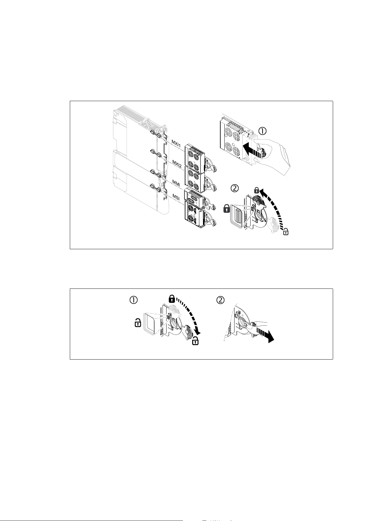
5.1.1 Assembly
[5-1] Assembly
5.1.2 Disassembly
[5-2] Disassembly
E94YCXX001G
E94AYCXX001H
22
Lenze · E94AYCIB communication module (INTERBUS) · Communication Manual · DMS 4.0 EN · 02/2014 · TD17
Page 23
5 Installation
5.2 Electrical installation
_ _ _ _ _ _ _ _ _ _ _ _ _ _ _ _ _ _ _ _ _ _ _ _ _ _ _ _ _ _ _ _ _ _ _ _ _ _ _ _ _ _ _ _ _ _ _ _ _ _ _ _ _ _ _ _ _ _ _ _ _ _ _ _
5.2 Electrical installation
Documentation for the standard device, host (PLC, master), system/machine
Observe the notes and wiring instructions contained in this documentation.
5.2.1 Wiring according to EMC guidelines
In typical systems, standard shielding is sufficient for the INTERBUS cable.
In environments with very strong interferences, the EMC compatibility can be improved by an
additional earthing of the cable shield.
For this observe the following notes:
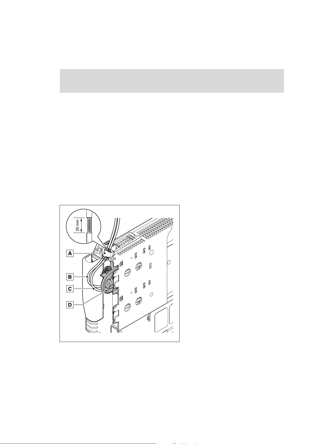
1. The distance of the additional earthing of the INTERBUS plug (Sub-D, 9-pole) depends on the
module slot and is as follows ...
• approx 10 cm for the upper slot (MXI1);
• approx. 20 cm for the lower slot (MXI2).
2. Measure the appropriate distance along the cables and, starting from this point, remove 2 cm
of the cable's plastic sheath.
3. Connect the cable shield to the shield sheet of the Servo Drive 9400.
[5-3] Wiring according to EMC guidelines
A Connection to the shield sheet of the Servo
Drive 9400
B IncomingINTERBUS line at X206 (IN)
C Outgoing INTERBUS line at X207 (OUT)
D Communication module in slot MXI1 of the
Servo Drive 9400
E94YCXX008
Lenze · E94AYCIB communication module (INTERBUS) · Communication Manual · DMS 4.0 EN · 02/2014 · TD17 23
Page 24
5 Installation
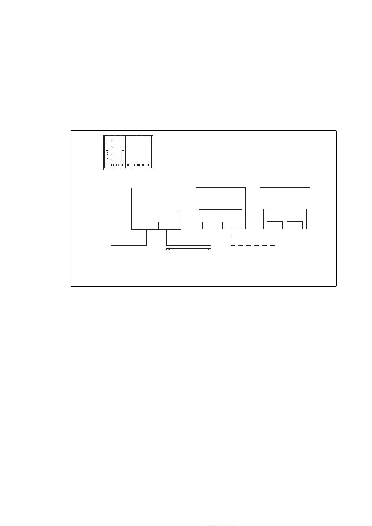
500 kBit/s: 400 m
2 MBit/s:£150 m£
Servo Drive
9400
E94AYCIB
X206
X207
Servo Drive
9400
E94AYCIB
X206
X207
Servo Drive
9400
E94AYCIB
X206
X207
OUT
IN
OUT
IN IN
M
S2
S1
Sn
5.2 Electrical installation
_ _ _ _ _ _ _ _ _ _ _ _ _ _ _ _ _ _ _ _ _ _ _ _ _ _ _ _ _ _ _ _ _ _ _ _ _ _ _ _ _ _ _ _ _ _ _ _ _ _ _ _ _ _ _ _ _ _ _ _ _ _ _ _
5.2.2 Wiring of the INTERBUS
For communication with the master and all further components, Servo Drives 9400 have to be
assembled with communication modules.
The INTERBUS system has to be designed as a ring. Here, go and return lines are integrated in the
same bus cable. The ring comes from the INTERBUS master via all other nodes back again to the
master.
An INTERBUS ring can consist of maximally 513 nodes (1 master + further slaves (slaves)).
[5-4] INTERBUS ring
M: Master (e.g. PLC, Industrial PC)
S1 ... Sn: Slaves
E94YCIB008
24
Lenze · E94AYCIB communication module (INTERBUS) · Communication Manual · DMS 4.0 EN · 02/2014 · TD17
Page 25

5 Installation
5.2 Electrical installation
_ _ _ _ _ _ _ _ _ _ _ _ _ _ _ _ _ _ _ _ _ _ _ _ _ _ _ _ _ _ _ _ _ _ _ _ _ _ _ _ _ _ _ _ _ _ _ _ _ _ _ _ _ _ _ _ _ _ _ _ _ _ _ _
5.2.3 INTERBUS connection
The INTERBUS of the communication module is connected via the 9-pole Sub-D plug X206 (input)
and the 9-pole Sub-D socket X207 (output).
[5-5] INTERBUS terminals X206 (input) and X207 (output)
Assignment of the 9-pole Sub-D plug X206 (IN)
Pin Name Input/output Description
1DO1 Input RS485: DO1 not inverted
2 DI1 Output RS485: DI1 not inverted
3GND Reference potential
4 Free not assigned
5Vcc5 Output 5 V DC
6 /DO1 Input RS485: DO1 inverted
7/DI1 Output RS485: DI1 inverted
8Vcc5 Output 5 V DC
9 Free not assigned
E94YCIB001C
Lenze · E94AYCIB communication module (INTERBUS) · Communication Manual · DMS 4.0 EN · 02/2014 · TD17 25
Page 26

5 Installation
5.2 Electrical installation
_ _ _ _ _ _ _ _ _ _ _ _ _ _ _ _ _ _ _ _ _ _ _ _ _ _ _ _ _ _ _ _ _ _ _ _ _ _ _ _ _ _ _ _ _ _ _ _ _ _ _ _ _ _ _ _ _ _ _ _ _ _ _ _
Assignment of the 9-pole Sub-D socket X207 (OUT)
Pin Name Input/output Description
1 DO2 Output RS485: DO2 not inverted
2 DI2 Input RS485: DI2 not inverted
3GND Reference potential
4GND
5Vcc5 Output 5 V DC
6/DO2 Output RS485: DO2 inverted
7 /DI2 Input RS485: DI2 inverted
8Vcc5 Output 5 V DC
9 RBST Signalling input Connection to the outgoing INTERBUS is plugged.
5.2.4 Dimensions of 9-pole sub-D connectors
Note!
Comply with the dimensions for width and depth of the 9-pole Sub-D connectors for the
INTERBUS terminals X206/X207.
[5-6] Dimensions of 9-pole sub-D connectors
26
E94YCIB001G
Lenze · E94AYCIB communication module (INTERBUS) · Communication Manual · DMS 4.0 EN · 02/2014 · TD17
Page 27

5 Installation
5.2 Electrical installation
_ _ _ _ _ _ _ _ _ _ _ _ _ _ _ _ _ _ _ _ _ _ _ _ _ _ _ _ _ _ _ _ _ _ _ _ _ _ _ _ _ _ _ _ _ _ _ _ _ _ _ _ _ _ _ _ _ _ _ _ _ _ _ _
5.2.5 Bus cable specification
The nodes at the bus system must be wired with one of the fieldbus cables that complies with the
INTERBUS specification.
A manufacturer of INTERBUS cables is e.g. PHOENIX CONTACT (Germany).
Note!
A cable which does not fulfil the requirements of the INTERBUS specification must not
be used!
Properties of the bus cable according to the INTERBUS specification
General properties
Cable type Sold by the meter
(e.g. PHOENIX CONTACT: IBS RBC meter-T, order no. 28 06 28 6)
No. of conductors 3 x 2, twisted in pairs, with joint shielding
Conductor cross-section > 0.2 mm
DC-cable resistance < 96 /km
Impedance (characteristic) • 120 ± 20 % (f = 64 kHz)
Capacitance per unit length < 60 nF/km (f = 800 Hz)
2
• 100 ± 15 (f > 1 MHz)
5.2.6 Bus cable length
Set the baud rate according to the length of the bus cable between the single INTERBUS nodes:
Baud rate Cable length between the single INTERBUS nodes
500 kbps max.400 m
2 Mbps max. 150 m
Note!
Select the baud rate which depends on the data volume, cycle time, and number of
nodes just high enough to suit your application.
Possible settings via DIP switch
Settings in »Engineer«
( 30)
( 34)
Lenze · E94AYCIB communication module (INTERBUS) · Communication Manual · DMS 4.0 EN · 02/2014 · TD17 27
Page 28

5 Installation
5.2 Electrical installation
_ _ _ _ _ _ _ _ _ _ _ _ _ _ _ _ _ _ _ _ _ _ _ _ _ _ _ _ _ _ _ _ _ _ _ _ _ _ _ _ _ _ _ _ _ _ _ _ _ _ _ _ _ _ _ _ _ _ _ _ _ _ _ _
5.2.7 External voltage supply
The communication module can be externally supplied with voltage via separate supply cables at
the 2-pin plug connector X205.
Note!
With external voltage supply, always use a separate power supply unit, safely separated
to EN 61800-5-1 in every control cabinet (SELV/PELV).
External voltage supply of the communication module is required if the communication via the bus
should be maintained when the supply of the standard device fails.
The parameters of a standard device separated from the mains cannot be accessed.
Assignment of the plug connector X205
Name Explanation
+ U = 24 V DC (+/- 10 %)
I = 180 mA
- Reference potential for external voltage supply
Terminal data
Range Values
Electrical connection 2-pin plug connector with spring connection
Possible connections Rigid:
2
1.5 mm
Flexible:
Without wire end ferrule
1.5 mm
With wire end ferrule, without plastic sleeve
1.5 mm
With wire end ferrule, with plastic sleeve
1.5 mm
Stripping length 9 mm
(AWG 16)
2
(AWG 16)
2
(AWG 16)
2
(AWG 16)
28
Lenze · E94AYCIB communication module (INTERBUS) · Communication Manual · DMS 4.0 EN · 02/2014 · TD17
Page 29

6 Commissioning
6.1 Before initial switch-on
_ _ _ _ _ _ _ _ _ _ _ _ _ _ _ _ _ _ _ _ _ _ _ _ _ _ _ _ _ _ _ _ _ _ _ _ _ _ _ _ _ _ _ _ _ _ _ _ _ _ _ _ _ _ _ _ _ _ _ _ _ _ _ _
6 Commissioning
During commissioning, system-related data such as motor parameters, operating parameters,
responses, and parameters for fieldbus communication are defined in the inverter. For Lenze
devices, this is done by means of codes.
The codes of the inverter and for communication are saved to the memory module in a non-volatile
data set.
In addition, there are codes for diagnosing and monitoring the stations.
Parameter reference
( 53)
Note!
When parameterising the communication module, please note that the code number
depends on the slot of the standard device into which the communication module is
plugged.
The first two digits of the code number indicate the slot:
•C13nnn for slot MXI1
Parameters of the communication module for slot MXI1
•C14nnn for slot MXI2
Parameters of the communication module for slot MXI2
You also have to set the Parameters of the standard device that are relevant to
communication ( 53).
6.1 Before initial switch-on
Stop!
( 55)
( 63)
Before switching on the Servo Drive 9400 and the communication module for the first
time, check the entire wiring for completeness, short circuit and earth fault.
Lenze · E94AYCIB communication module (INTERBUS) · Communication Manual · DMS 4.0 EN · 02/2014 · TD17 29
Page 30

6 Commissioning
6.2 Possible settings via DIP switch
_ _ _ _ _ _ _ _ _ _ _ _ _ _ _ _ _ _ _ _ _ _ _ _ _ _ _ _ _ _ _ _ _ _ _ _ _ _ _ _ _ _ _ _ _ _ _ _ _ _ _ _ _ _ _ _ _ _ _ _ _ _ _ _
6.2 Possible settings via DIP switch
The following can be set via the S205 DIP switch:
• Number of the process data words
switches: 1 ... 4
• Number of the parameter data words
switches: 5 and 6
•Baud rate
switch: 8
Lenze setting: All switches "OFF"
Switch 7 has no function.
E94YCIB001D
[6-1] DIP switch
( 31)
( 32)
( 33)
Note!
• All DIP switches = "OFF" (Lenze setting):
At switch-on, the configuration from the codes gets active (Settings in »Engineer«
( 34)
).
• At least one DIP switch = "ON":
At switch-on, the values are accepted from the switch positions.
• The data word sum (process data words + parameter data words) has to consist of
1 ... 10 words (16 bits/word).
• Switch off the voltage supply of the communication module and afterwards on again
to activate changed settings.
30
Lenze · E94AYCIB communication module (INTERBUS) · Communication Manual · DMS 4.0 EN · 02/2014 · TD17
Page 31

6 Commissioning
12345678
ON
OFF
6.2 Possible settings via DIP switch
_ _ _ _ _ _ _ _ _ _ _ _ _ _ _ _ _ _ _ _ _ _ _ _ _ _ _ _ _ _ _ _ _ _ _ _ _ _ _ _ _ _ _ _ _ _ _ _ _ _ _ _ _ _ _ _ _ _ _ _ _ _ _ _
6.2.1 Setting the number of process data words
• The number of process data words can be set via the switches 1 ... 4.
• 0 ... 10 process data words can be used.
• The current setting is displayed in the »Engineer« in C13860/2
/ C14860/2.
Note!
The data word sum (process data word + parameter data words) has to consist of 1 ... 10
words (16 bits/word).
Impermissible settings are reported by the BE LED (red blinking).
LED status displays
The communication module then operates internally with the following values:
• 2 process data words (PD)
• 1 parameter data word (PCP)
( 47)
DIP switch Number of
PD
0 OFF OFF OFF OFF 4
1 OFF OFF OFF ON
2OFFOFFON OFF
3OFFOFFON ON
4OFFON OFF OFF
5OFFON OFF ON
6OFFON ON OFF
7OFFON ON ON 2
8 ON OFF OFF OFF
9 ON OFF OFF ON 1
10 ON OFF ON OFF 0
Switch Max. number
1 2 3 4
of PCP
Lenze · E94AYCIB communication module (INTERBUS) · Communication Manual · DMS 4.0 EN · 02/2014 · TD17 31
Page 32

6 Commissioning
12345678
ON
OFF
6.2 Possible settings via DIP switch
_ _ _ _ _ _ _ _ _ _ _ _ _ _ _ _ _ _ _ _ _ _ _ _ _ _ _ _ _ _ _ _ _ _ _ _ _ _ _ _ _ _ _ _ _ _ _ _ _ _ _ _ _ _ _ _ _ _ _ _ _ _ _ _
6.2.2 Setting the number of parameter data words
• The number of parameter data words can be set via the switches 5 and 6.
• 0, 1, 2 order 4 parameter data words can be used.
• The current setting is displayed in the »Engineer« in C13860/1
/ C14860/1.
Note!
The data word sum (process data word + parameter data words) has to consist of 1 ... 10
words (16 bits/word).
Impermissible settings are reported by the BE LED (red blinking).
LED status displays
The communication module then operates internally with the following values:
• 2 process data words (PD)
• 1 parameter data word (PCP)
( 47)
DIP switch Number of PCP Switch Max. number of
5 6
0OFFOFF100x03
1OFFON 90xE3
PD
ID code
[hex]
2 ON OFF 8 0xE0
4 ON ON 60xE1
32
Lenze · E94AYCIB communication module (INTERBUS) · Communication Manual · DMS 4.0 EN · 02/2014 · TD17
Page 33

6 Commissioning
12345678
ON
OFF
6.2 Possible settings via DIP switch
_ _ _ _ _ _ _ _ _ _ _ _ _ _ _ _ _ _ _ _ _ _ _ _ _ _ _ _ _ _ _ _ _ _ _ _ _ _ _ _ _ _ _ _ _ _ _ _ _ _ _ _ _ _ _ _ _ _ _ _ _ _ _ _
6.2.3 Setting the baud rate
Note!
Select the baud rate which depends on the data volume, cycle time, and number of
nodes just high enough to suit your application.
• The baud rate can be set via the switch 8.
• Set the baud rate according to the length of the bus cable between the single INTERBUS nodes.
• The current setting is displayed in the »Engineer« in C13863
DIP switch Switch 8 Baud rate Cable length between adjacent nodes
OFF 500 kbps max. 400 m
/ C14863.
ON 2 Mbps max. 150 m
Lenze · E94AYCIB communication module (INTERBUS) · Communication Manual · DMS 4.0 EN · 02/2014 · TD17 33
Page 34

6 Commissioning
6.3 Settings in »Engineer«
_ _ _ _ _ _ _ _ _ _ _ _ _ _ _ _ _ _ _ _ _ _ _ _ _ _ _ _ _ _ _ _ _ _ _ _ _ _ _ _ _ _ _ _ _ _ _ _ _ _ _ _ _ _ _ _ _ _ _ _ _ _ _ _
6.3 Settings in »Engineer«
Note!
The data word sum (process data words + parameter data words) has to consist of 1 ... 10
words (16 bits/word).
Impermissible settings are reported by the BE LED (red blinking).
LED status displays
The communication module then operates internally with the following values:
• 2 process data words
• 1 parameter data word
Setting Description
Select the baud rate which depends on the data volume, cycle time, and number of
nodes just high enough to suit your application.
PCP data length 0, 1, 2 or 4 parameter data words can be used (C13892
Process data length 1 ... 10 process data words can be used (C13893
Clear process data Setting (C13885
Baud rate Set the baud rate (C13894
( 47)
/ C14892).
/ C14893).
/ C14885) the selection of the process data the Servo Drive
9400 is to process for maintaining the internal communication when the
INTERBUS has exited the "IBS-ACTIVE" state.
• 0: Use of the last master process data
• 1: PDOs are set to the value "0". (Standard setting)
/ C14894) according to the length of the bus cable
between the single INTERBUS nodes:
• 500 kbps: Max. 400 m between the single nodes
• 2 Mbps: Max. 150 m between the single nodes
34
How to activate changed settings in the »Engineer«:
1. Execute the device command C00002 = "11: Save start parameters".
2. Carry out a "Reset node" of the node, or
module off and then on again.
Lenze · E94AYCIB communication module (INTERBUS) · Communication Manual · DMS 4.0 EN · 02/2014 · TD17
switch the voltage supply of the communication
Page 35

6 Commissioning
6.4 Initial switch-on
_ _ _ _ _ _ _ _ _ _ _ _ _ _ _ _ _ _ _ _ _ _ _ _ _ _ _ _ _ _ _ _ _ _ _ _ _ _ _ _ _ _ _ _ _ _ _ _ _ _ _ _ _ _ _ _ _ _ _ _ _ _ _ _
6.4 Initial switch-on
Documentation for the standard device
Observe the safety instructions and information on residual hazards.
Note!
Establishing communication
In order to establish communication via an externally supplied communication module,
the standard device must be switched on as well.
For further communication of the externally supplied module it is not relevant whether
the standard device is switched on or not.
Protection against uncontrolled restart
After a fault (e.g. short-term mains failure), it is sometimes undesirable or even
impermissible for the drive to restart.
In the Lenze setting of Servo Drives 9400, the restart protection is activated.
The restart behaviour of the inverter can be set via C00142 ("auto restart after mains
connection"):
C00142 = "0: Inhibited" (Lenze setting)
• The inverter remains inhibited (even if the fault is no longer active).
• An explicit controller enable causes the drive to start up in a controlled manner: LOWHIGH edge at digital input X5/RFR.
C00142 = "1: Enabled"
• An uncontrolled restart of the drive is possible.
Lenze · E94AYCIB communication module (INTERBUS) · Communication Manual · DMS 4.0 EN · 02/2014 · TD17 35
Page 36

7 Data transfer
_ _ _ _ _ _ _ _ _ _ _ _ _ _ _ _ _ _ _ _ _ _ _ _ _ _ _ _ _ _ _ _ _ _ _ _ _ _ _ _ _ _ _ _ _ _ _ _ _ _ _ _ _ _ _ _ _ _ _ _ _ _ _ _
7 Data transfer
The INTERBUS transmits parameter data, configuration data, diagnostic data, alarm messages and
process data between the host (master) and the inverters (slaves) participating in the fieldbus.
Depending on their time-critical nature, the data are transmitted via different communication
channels.
Communication channels
The process data channel transmits process data.
• The process data serve to control the inverter.
• The transmission of process data is time-critical.
• Process data are cyclically transferred between the host (master) and the inveters connected to
the fieldbus (slaves) (continuous exchange of current input and output data).
• The host (master) can directly access the process data. In the PLC, for instance, the data are
directly saved to the IO area.
• 0 ... 10 process data words can be used.
• Process data are not saved in the inverter.
• Process data are e.g. setpoints, actual values, control words, and status words.
The parameter data channel serves to transfer parameter data.
• The parameter data channel provides access to all Lenze codes.
• The transmission of parameter data is usually not time-critical.
• Parameter data are, for instance, operating parameters, diagnostic information, and motor
data.
• 0, 1, 2 order 4 parameter data words can be used.
• The parameter data is transmitted in accordance with the Peripherials Communication Protocol
(PCP).
• The parameter data channel is identical for both transmission directions.
Note!
The data word sum (process data words + parameter data words) has to consist of 1 ... 10
words (16 bits/word).
Please observe the direction of the flow of information:
• Input data (Rx data): Process data from the inverter (slave) to the master
• Output data (Tx data): Process data from the master to the inverter (slave)
36 Lenze · E94AYCIB communication module (INTERBUS) · Communication Manual · DMS 4.0 EN · 02/2014 · TD17
Page 37

8 Process data transfer
_ _ _ _ _ _ _ _ _ _ _ _ _ _ _ _ _ _ _ _ _ _ _ _ _ _ _ _ _ _ _ _ _ _ _ _ _ _ _ _ _ _ _ _ _ _ _ _ _ _ _ _ _ _ _ _ _ _ _ _ _ _ _ _
8 Process data transfer
Configuring process data (PDO mapping)
The Servo Drives 9400 enable the individual mapping of process data. For this purpose, the
»Engineer« is provided with a port configurator.
Note!
• The port mapping for the Servo Drive 9400 is no configuration that can be carried out
online. For this purpose, an update of the »Engineer« project and a subsequent
download of the application is always required.
• The data word sum (process data words + parameter data words) has to consist of
1 ... 10 words (16 bits/word).
How to set the PDO mapping with the »Engineer«:
1. The process data mapping to the port variables is executed in the »Engineer« under the
Process data objects tab of the corresponding fieldbus communication module:
2. Select the receive object PDO_RX0:
Lenze · E94AYCIB communication module (INTERBUS) · Communication Manual · DMS 4.0 EN · 02/2014 · TD17 37
Page 38

8 Process data transfer
_ _ _ _ _ _ _ _ _ _ _ _ _ _ _ _ _ _ _ _ _ _ _ _ _ _ _ _ _ _ _ _ _ _ _ _ _ _ _ _ _ _ _ _ _ _ _ _ _ _ _ _ _ _ _ _ _ _ _ _ _ _ _ _
3. Click the Edit PDO button.
The selection window for editing the process data object is opened:
Here you can transfer the individual ports from the Port Selection list to the receive PDO
"PDO_RX0" by clicking the >> button.
The Up and Down buttons serve to shift the sequence of the ports within the PDOs.
4. Confirm the selection with OK.
5. Repeat the steps 2. to 4. for the transmit object PDO_TX0.
6. Then link the ports to application signals in the technology application selected.
The »FB Editor« can be activated in the multiplexer codes (> C03000), if necessary.
If the »FB Editor« is activated, the multiplexer codes (> C03000) are no longer available. In
this case, you must carry out the interconnection directly in the »FB Editor«.
38 Lenze · E94AYCIB communication module (INTERBUS) · Communication Manual · DMS 4.0 EN · 02/2014 · TD17
Page 39

9 Parameter data transfer
9.1 Addressing of the parameter data
_ _ _ _ _ _ _ _ _ _ _ _ _ _ _ _ _ _ _ _ _ _ _ _ _ _ _ _ _ _ _ _ _ _ _ _ _ _ _ _ _ _ _ _ _ _ _ _ _ _ _ _ _ _ _ _ _ _ _ _ _ _ _ _
9 Parameter data transfer
The parameter data of Lenze devices are contained in codes which are listed in this documentation
and the documentation of the Servo Drive 9400.
Parameter reference
9.1 Addressing of the parameter data
The parameters of a Lenze device are not directly addressed via codes but via an index and subindex.
The conversion is made via an offset: 24575 or 0x5FFF
• INTERBUS index (decimal) = 24575 - Lenze code number (decimal)
• INTERBUS index (hexadecimal) = 0x5FFF - Lenze code number (hexadecimal)
Example of C00105 (deceleration time quick stop (QSP)):
• INTERBUS index (decimal) = 24575 - 105 = 24470
( 53)
• INTERBUS index (hexadecimal) = 0x5FFF - 0x69 = 0x5F96
Parameter changes must be saved via code C00002 of the Servo Drive 9400.
Lenze · E94AYCIB communication module (INTERBUS) · Communication Manual · DMS 4.0 EN · 02/2014 · TD17 39
Page 40

9 Parameter data transfer
9.2 Initialising PCP communication
_ _ _ _ _ _ _ _ _ _ _ _ _ _ _ _ _ _ _ _ _ _ _ _ _ _ _ _ _ _ _ _ _ _ _ _ _ _ _ _ _ _ _ _ _ _ _ _ _ _ _ _ _ _ _ _ _ _ _ _ _ _ _ _
9.2 Initialising PCP communication
Make entries into the CRL (communication relation list) in order that communication between the
INTERBUS master and the communication module can take place.
Make the following entries in the CRL of the INTERBUS master:
Field name Entry
Communication reference 2
Connection type Master slave acyclic
Connection attribute Defined
Max-PDU Sending-High-Prio 0
Max-PDU Sending-Low-Prio 64
Max-PDU Receiving-High-Prio 0
Max-PDU Receiving-Low-Prio 64
Supported Services Request 0x803000
Supported Services Response 0x000000
Maximum SCC 1
Maximum RCC 1
Maximum SAC 1
Maximum RAC 1
40
Lenze · E94AYCIB communication module (INTERBUS) · Communication Manual · DMS 4.0 EN · 02/2014 · TD17
Page 41

9 Parameter data transfer
9.3 Supported PMS services
_ _ _ _ _ _ _ _ _ _ _ _ _ _ _ _ _ _ _ _ _ _ _ _ _ _ _ _ _ _ _ _ _ _ _ _ _ _ _ _ _ _ _ _ _ _ _ _ _ _ _ _ _ _ _ _ _ _ _ _ _ _ _ _
9.3 Supported PMS services
The parameter data is transferred via PMS services.
In the following, only parameters and their contents are given that are returned by the Lenze
inverters. All other transfer parameters of the given PMS services can be obtained from the
corresponding descriptions of the INTERBUS master.
The following PMS services are supported by Lenze inverters:
• Initiate: Establish a connection of the INTERBUS master to the inverter
• Abort: Abort connection
• Reject: Reject impermissible PMS service
• Read: Read parameters
• Write: Write parameters
• Get-OD: Read out the object directory
•Identify: Identification of the inverter
• Status: Read the status of the inverter
9.3.1 Initiate
The "Initiate" PMS service establishes a logic connection between the INTERBUS master and the
communication module.
The inverter provides the following parameters:
Name Value Description
Profile number 0 No profile is supported.
Password 0 The password function of INTERBUS is not supported.
Access groups 0 No access groups exist.
Access-Protection Supported TRUE Access protection is supported.
Version OD 0 Version of the object directory
9.3.2 Abort
The "Abort" PMS service aborts a logic connection between the INTERBUS master and the
communication module.
9.3.3 Reject
The "Reject" PMS service rejects a non-supported PMS service.
Lenze · E94AYCIB communication module (INTERBUS) · Communication Manual · DMS 4.0 EN · 02/2014 · TD17 41
Page 42

9 Parameter data transfer
9.3 Supported PMS services
_ _ _ _ _ _ _ _ _ _ _ _ _ _ _ _ _ _ _ _ _ _ _ _ _ _ _ _ _ _ _ _ _ _ _ _ _ _ _ _ _ _ _ _ _ _ _ _ _ _ _ _ _ _ _ _ _ _ _ _ _ _ _ _
9.3.4 Read/Write
The "Read" PMS service reads parameters from the inverter. The inverter outputs the requested
parameter or an error message.
The "Write" PMS service writes on parameters of the inverter. The inverter outputs a positive
feedback or an error message.
The following error messages can occur:
Error Class Error code Additional
6 3 0x00 No access authorisation
6 5 0x10 Impermissible job parameter
650x11Invalid subindex
6 5 0x12 Data length too large
6 5 0x13 Data length too small
6 6 0x00 Object is no parameter
6 7 0x00 Object does not exist
6 8 0x00 Data types do not comply with each other
8 0 0x00 Request cannot be executed
8 0 0x20 Request cannot be executed at the moment
8 0 0x21 Cannot be executed because of local control
8 0 0x22 Cannot be executed because of device state
8 0 0x30 Quit value range / parameter can only be changed when the
8 0 0x31 Parameter value too high
8 0 0x32 Parameter value too low
8 0 0x33 Sub parameter outside the value range
8 0 0x34 Value of the subparameter is too high
8 0 0x35 Value of the subparameter is too low
8 0 0x36 Maximum value is lower than minimum value
8 0 0x41 Communication object cannot be displayed on process data
8 0 0x42 Length of the process data exceeded
8 0 0x43 General collision with other values
Code
[hex]
Description
controller is inhibited.
9.3.5 Get-OD
The "Get-OD" PMS service reads out the object description for every parameter and data type.
42
Lenze · E94AYCIB communication module (INTERBUS) · Communication Manual · DMS 4.0 EN · 02/2014 · TD17
Page 43

9 Parameter data transfer
9.3 Supported PMS services
_ _ _ _ _ _ _ _ _ _ _ _ _ _ _ _ _ _ _ _ _ _ _ _ _ _ _ _ _ _ _ _ _ _ _ _ _ _ _ _ _ _ _ _ _ _ _ _ _ _ _ _ _ _ _ _ _ _ _ _ _ _ _ _
9.3.6 Identify
The P "Identify" MS service provides information on how to identify the inverter.
The inverter with the plugged-on communication module provides the following parameters for
this:
Parameter Type Description
Device manufacturer Visible string Company name "Lenze"
Device type Visible-string (15 characters) Device name for inverter and communication
Device version Visible-string (15 characters) Firmware version of the inverter and the
Example: Visible string "device type" (15 characters)
1 2 3 4 5 6 7 8 9 10 11 12 13 14 15
E 9 4 A F H B A F C I B
module
communication module
Character Description
1 ... 3 Product range of the inverter and the communication module ("E94" = 9400 series)
4Blank
5 ... 8 Firmware of the inverter (from C00200/0)
• Character 5: Version ("A" = 1st generation)
• Character 6 ... 8: Firmware version
• "FHB" = Servo Drive 9400 HighLine
• "FRB" = Servo Drive 9400 regenerative power supply module
• "VPB" = Servo Drive 9400 PLC
9Blank
10 ... 14 Firmware of the communication module (from C13900
• Character 10: Version ("A" = 1st generation)
• Characters 11 ... 14: Firmware version
• "FCIB" = INTERBUS module
15 Blank
/ C14900)
Example: Visible string "device version" (15 characters)
1 2 3 4 5 6 7 8 9 10 11 12 13 14 15
0 5 . 0 0 0 1 . 0 0
Character Description
1 ... 5 Firmware version of the inverter (from C00099/0 = "05.00.xx.yy", without internal revision status
6Blank
7 ... 11 Firmware version of the communication module (from C13902
12...15 Blank
["xx"] and build status ["yy"])
/ C14902 = "01.00.xx", without
internal revision status ["xx"])
Lenze · E94AYCIB communication module (INTERBUS) · Communication Manual · DMS 4.0 EN · 02/2014 · TD17 43
Page 44

9 Parameter data transfer
9.3 Supported PMS services
_ _ _ _ _ _ _ _ _ _ _ _ _ _ _ _ _ _ _ _ _ _ _ _ _ _ _ _ _ _ _ _ _ _ _ _ _ _ _ _ _ _ _ _ _ _ _ _ _ _ _ _ _ _ _ _ _ _ _ _ _ _ _ _
9.3.7 Status
The "Status" PMS service provides status information about the inverter.
The inverter provides the following values:
Status Value Description
Logical status 0 = ready for communication Information about the current operating
Physical status • 0 = ready for operation (device state
"OPERATION ENABLED")
• 1 = ready for operation to a limited extent
(all other device states)
Local Detail 0 Is not supported.
mode of the inverter with regard to
communication
Information about the current operating
status of the
inverter.
44
Lenze · E94AYCIB communication module (INTERBUS) · Communication Manual · DMS 4.0 EN · 02/2014 · TD17
Page 45

10 Monitoring
10.1 Interruption of the INTERBUS communication
_ _ _ _ _ _ _ _ _ _ _ _ _ _ _ _ _ _ _ _ _ _ _ _ _ _ _ _ _ _ _ _ _ _ _ _ _ _ _ _ _ _ _ _ _ _ _ _ _ _ _ _ _ _ _ _ _ _ _ _ _ _ _ _
10 Monitoring
10.1 Interruption of the INTERBUS communication
An interruption of the INTERBUS communication, e.g. by cable break or failure of the host (PLC,
master), is recognised by the communication module.
Responses to communication faults can be set in the Monitoring tab:
Settings Description
Response to interrupted
INTERBUS communication
Response time if the INTERBUS
communication is interrupted
When the INTERBUS communication is interrupted, the response set here
(C13880/1
A change in the monitoring response becomes immediately effective.
If the "IBS-ACTIVE" status (INTERBUS active, cyclic data exchange) is left, the
response set under takes place after the response time set here
(C13881
• A value of "65535" in this code deactivates the monitoring function.
• A change in the monitoring is immediately effective.
• The monitoring time elapses when the "IBS-ACTIVE" status is left.
• After this response delay has elapsed, the response set is executed with
/ C14880/1) takes place in the inverter.
/ C14881) has elapsed.
the error message "INTERBUS: Data exchange stopped [0x00c88131]
( 52).
"
If the Servo Drive 9400 does not receive any valid process data in the "IBS-ACTIVE" state, the setting
in C13885
/ C14885 is taken as a basis for the process data. (Like this the data sent last by the master
can be used or reset to zero.)
Settings in »Engineer«
( 34)
Lenze · E94AYCIB communication module (INTERBUS) · Communication Manual · DMS 4.0 EN · 02/2014 · TD17 45
Page 46

10 Monitoring
10.2 Interruption of internal communication
_ _ _ _ _ _ _ _ _ _ _ _ _ _ _ _ _ _ _ _ _ _ _ _ _ _ _ _ _ _ _ _ _ _ _ _ _ _ _ _ _ _ _ _ _ _ _ _ _ _ _ _ _ _ _ _ _ _ _ _ _ _ _ _
10.2 Interruption of internal communication
The response to a communication error between the communication module and the Servo Drive
9400 can be set via these codes:
• C01501
• C01502
(module in slot MXI1)
(module in slot MXI2)
46
Lenze · E94AYCIB communication module (INTERBUS) · Communication Manual · DMS 4.0 EN · 02/2014 · TD17
Page 47

11 Diagnostics
11.1 LED status displays
_ _ _ _ _ _ _ _ _ _ _ _ _ _ _ _ _ _ _ _ _ _ _ _ _ _ _ _ _ _ _ _ _ _ _ _ _ _ _ _ _ _ _ _ _ _ _ _ _ _ _ _ _ _ _ _ _ _ _ _ _ _ _ _
11 Diagnostics
For purposes of fault diagnostics, the communication module is provided with the LEDs on the front.
Furthermore you can carry out the Diagnosing with the »Engineer«
11.1 LED status displays
( 48).
Note!
During normal operation, the LED BS blinks and the LED MS is permanently lit.
LEDs Pos. Colour Status Description
MS Green On The communication module is supplied with voltage
Blinking The communication module is supplied with voltage,
ME Red On An error has occurred in the communication module.
BS Green Blinking The INTERBUS communication has been established
Off The communication module is not active at the
BE Red On The INTERBUS communication has been interrupted.
Blinking Impermissible setting:
E94YCIB001E
DE Red On The communication module is not accepted by the
and is connected to the standard device.
but has no connection to the standard device. (The
standard device is either switched off, in the
initialisation phase, or not available).
via the communication module. The INTERBUS is
active. Data cycles are executed.
fieldbus. Data cycles are not executed.
Data cycles are not executed.
• Process data words + parameter data words
>10
• Process data words + parameter data words
=0
The communication module has been initialised and
operates internally with the following values:
•2 process data words
• 1 parameter data word
basic device or the basic device is not active (see
notes in the documentation relating to the basic
device.)
Lenze · E94AYCIB communication module (INTERBUS) · Communication Manual · DMS 4.0 EN · 02/2014 · TD17 47
Page 48

11 Diagnostics
11.2 Diagnosing with the »Engineer«
_ _ _ _ _ _ _ _ _ _ _ _ _ _ _ _ _ _ _ _ _ _ _ _ _ _ _ _ _ _ _ _ _ _ _ _ _ _ _ _ _ _ _ _ _ _ _ _ _ _ _ _ _ _ _ _ _ _ _ _ _ _ _ _
11.2 Diagnosing with the »Engineer«
In the »Engineer« under the Diagnostics tab, you will find INTERBUS diagnostics information.
Querying the current bus status
C13861
Value
C13861/14861
[hex]
0xyyy0 IBS-INIT Initialisation
0xyyy1 IBS-ACTIVE The bus is active. Data cycles are executed.
0xyyy2 IBS-READY The bus is ready for operation. No data cycles are executed.
yyy = device-internal use
/ C14861 displays the bus status of the INTERBUS node:
Bus status Description
48
Lenze · E94AYCIB communication module (INTERBUS) · Communication Manual · DMS 4.0 EN · 02/2014 · TD17
Page 49

12 Error messages
12.1 Short overview of the INTERBUS error messages
_ _ _ _ _ _ _ _ _ _ _ _ _ _ _ _ _ _ _ _ _ _ _ _ _ _ _ _ _ _ _ _ _ _ _ _ _ _ _ _ _ _ _ _ _ _ _ _ _ _ _ _ _ _ _ _ _ _ _ _ _ _ _ _
12 Error messages
This chapter supplements the error list for the Servo Drive 9400 contained in the reference manual
and in the »Engineer« online help with the error messages of the communication module.
Reference manual/»Engineer« online help for the Servo Drive 9400
Here you will find general information on diagnostics & fault analysis and on error
messages.
12.1 Short overview of the INTERBUS error messages
The following table lists all INTERBUS error messages in the numerical order of the error numbers.
Furthermore, the preset error response and - if available - the parameter for setting the error
response are specified.
Tip!
If you click on the cross-reference in the first column, you will get a detailed description
(causes and remedies) of the corresponding error message.
Error number Name Response (Lenze setting) Adjustable in
hex dec
0x00c85531
0x00c85532
0x00c85533
0x00c86010
0x00c86011
0x00c86100
0x00c86101
0x00c86110
0x00c8641f
0x00c86420
0x00c88125
0x00c88126
0x00c88127
0x00c88131
0x00c88211 13140497 INTERBUS: Received process data length is contradictory 5: Warning -
0x00c88212
13129009 INTERBUS: No access to the memory 6: Information -
13129010 INTERBUS: Error while reading the memory 6: Information -
13129011 INTERBUS: Error while writing into the memory 6: Information -
13131792 INTERBUS: Internal error 1: No Response -
13131793 INTERBUS: Internal error 1: No Response -
13132032 INTERBUS: Internal error 1: No Response -
13132033 INTERBUS: Internal error 1: No Response -
13132048 INTERBUS: Internal mapping error 4: Warning locked -
13132831 INTERBUS: Parameter set invalid 1: No Response -
13132832 INTERBUS: Lenze setting loaded 1: No Response -
13140261 INTERBUS: Invalid configuration 5: Warning -
13140262 INTERBUS: Reset of communication 1: No Response -
13140263 INTERBUS: Invalid initialisation 5: Warning -
13140273 INTERBUS: Data exchange stopped None C13880/1 /
13140498 INTERBUS: Process data length to be sent is contradictory 5: Warning -
C14880/1
Lenze · E94AYCIB communication module (INTERBUS) · Communication Manual · DMS 4.0 EN · 02/2014 · TD17 49
Page 50

12 Error messages
12.2 Possible causes and remedies
_ _ _ _ _ _ _ _ _ _ _ _ _ _ _ _ _ _ _ _ _ _ _ _ _ _ _ _ _ _ _ _ _ _ _ _ _ _ _ _ _ _ _ _ _ _ _ _ _ _ _ _ _ _ _ _ _ _ _ _ _ _ _ _
12.2 Possible causes and remedies
This chapter lists all INTERBUS error messages in the numerical order of the error numbers. Possible
causes and remedies as well as responses to the error messages are described in detail.
INTERBUS: No access to memory [0x00c85531]
Response (Lenze setting printed in bold) Setting: not possible
None System error Error Fault Quick stop by trou ble Warning locked Warning Information
Cause Remedy
Memory could not be accessed. Send module with error description to Lenze.
INTERBUS: Error while reading the memory [0x00c85532]
Response (Lenze setting printed in bold) Setting: not possible
None System error Error Fault Quick stop by trou ble Warning locked Warning Information
Cause Remedy
Parameter could not be read. Send module with error description to Lenze.
INTERBUS: Error while writing into the memory [0x00c85533]
Response (Lenze setting printed in bold) Setting: not possible
None System fault Fault Trouble Quick stop by trouble Warning locked Warning Information
INTERBUS: Internal error [0x00c86010]
INTERBUS: Internal error [0x00c86011]
Cause Remedy
Parameter could not be written. Send module with error description to Lenze.
Response (Lenze setting printed in bold) Setting: not possible
None System fault Fault Trouble Quick stop by trouble Warning locked Warning Information
Cause Remedy
Module is defective. Send module with error description to Lenze.
Response (Lenze setting printed in bold) Setting: not possible
None System fault Fault Trouble Quick stop by trouble Warning locked Warning Information
Cause Remedy
Module is defective. Send module with error description to Lenze.
INTERBUS: Internal error [0x00c86100]
Response (Lenze setting printed in bold)
None System fault Fault Trouble Quick stop by trouble Warning locked Warning Information
Cause Remedy
Module is defective. Send module with error description to Lenze.
50
Setting: not possible
Lenze · E94AYCIB communication module (INTERBUS) · Communication Manual · DMS 4.0 EN · 02/2014 · TD17
Page 51

12 Error messages
12.2 Possible causes and remedies
_ _ _ _ _ _ _ _ _ _ _ _ _ _ _ _ _ _ _ _ _ _ _ _ _ _ _ _ _ _ _ _ _ _ _ _ _ _ _ _ _ _ _ _ _ _ _ _ _ _ _ _ _ _ _ _ _ _ _ _ _ _ _ _
INTERBUS: Internal error [0x00c86101]
Response (Lenze setting printed in bold) Setting: not possible
None System fault Fault Trouble Quick stop by trouble Warning locked Warning Information
Cause Remedy
Internal error Send module with error description to Lenze.
INTERBUS: Internal mapping error [0x00c86110]
Response (Lenze setting printed in bold) Setting: not possible
None System fault Fault Trouble Quick stop by trouble Warning locked Warning Information
Cause Remedy
The selected PDO mapping is invalid:
• An object not supporting the required properties has
been specified.
• The data word sum (process data words + parameter
data words) has to consist of 1 ... 10 words (16 bits/
word).
Repeat Configuring process data (PDO mapping)
( 37).
INTERBUS: Invalid parameter set [0x00c8641f]
Response (Lenze setting printed in bold) Setting: not possible
None System fault Fault Trouble Quick stop by trouble Warning locked Warning Information
Cause Remedy
No active parameter set could be loaded. Download application again (including module).
INTERBUS: Lenze setting loaded [0x00c86420]
Response (Lenze setting printed in bold) Setting: not possible
None System fault Fault Trouble Quick stop by trouble Warning locked Warning Information
Cause Remedy
Access via standard device to the parameter set in the
memory module failed.
INTERBUS: Invalid configuration [0x00c88125]
Response (Lenze setting printed in bold) Setting: not possible
None System error Error Fault Quick stop by trou ble Warning locked Warning Information
Cause Remedy
The active configuration is invalid:
• Process data words + parameter data words > 10
• Process data words + parameter data words = 0
The data word sum (process data words + parameter
data words) has to consist of 1 ... 10 words (16 bits/
word).
Download application again (including module).
Adapt the number of process data words and parameter
data words:
• Process data words + parameter data words = 1 ... 10
INTERBUS: Reset of the communication stack [0x00c88126]
Response (Lenze setting printed in bold) Setting: not possible
None System fault Fault Trouble Quick stop by trouble Warning locked warning Information
Cause Remedy
Error when processing the INTERBUS services Execute renewed initialisation by the master.
Lenze · E94AYCIB communication module (INTERBUS) · Communication Manual · DMS 4.0 EN · 02/2014 · TD17 51
Page 52

12 Error messages
12.2 Possible causes and remedies
_ _ _ _ _ _ _ _ _ _ _ _ _ _ _ _ _ _ _ _ _ _ _ _ _ _ _ _ _ _ _ _ _ _ _ _ _ _ _ _ _ _ _ _ _ _ _ _ _ _ _ _ _ _ _ _ _ _ _ _ _ _ _ _
INTERBUS: Invalid initialisation [0x00c88127]
Response (Lenze setting printed in bold) Setting: not possible
None System error Error Fault Quick stop by trou ble Warning locked Warning Information
Cause Remedy
The INTERBUS initialisation has failed. Execute renewed initialisation by the master.
INTERBUS: Data exchange stopped [0x00c88131]
Response (Lenze setting printed in bold) Setting: C13880/1 / C14880/1
None System fault Fault Trouble Quick stop by trouble Warning locked Warning Information
Cause Remedy
Data exchange via INTERBUS has been stopped. • Check cables and terminals.
• Execute renewed initialisation by the master.
INTERBUS: Received process data length is contradictory [0x00c88211]
Response (Lenze setting printed in bold) Setting: not possible
None System error Error Fault Quick stop by trou ble Warning locked Warning Information
Cause Remedy
The number of received I/O data via INTERBUS (display in
C13860/2
number configured by the device through port mapping
(display in C13854/1
The data word sum (process data word + parameter data
INTERBUS: Process data length to be sent is contradictory [0x00c88212]
words) has to consist of 1 ... 10 words (16 bits/word).
Response (Lenze setting printed in bold) Setting: not possible
None System error Error Fault Quick stop by trou ble Warning locked Warning Information
Cause Remedy
The number of I/O data to be sent via INTERBUS (display
in C13860/2
number configured by the device through port mapping
(display in C13855/1
The data word sum (process data word + parameter data
words) has to consist of 1 ... 10 words (16 bits/word).
/ C14860/2) does not correspond to the
/ C14854/1).
/ C14860/2) does not correspond to the
/ C14855/1).
Check whether the differing data length is sufficient for
the application.
If required, adapt the port mapping or the I/O data
length of the received data.
Configuring process data (PDO mapping)
Setting the number of process data words
Check whether the differing data length is sufficient for
the application.
If required, adapt the port mapping or the I/O data
length of the data to be sent.
Configuring process data (PDO mapping)
Setting the number of process data words
( 37)
( 31)
( 37)
( 31)
52
Lenze · E94AYCIB communication module (INTERBUS) · Communication Manual · DMS 4.0 EN · 02/2014 · TD17
Page 53

13 Parameter reference
13.1 Parameters of the standard device that are relevant to communication
_ _ _ _ _ _ _ _ _ _ _ _ _ _ _ _ _ _ _ _ _ _ _ _ _ _ _ _ _ _ _ _ _ _ _ _ _ _ _ _ _ _ _ _ _ _ _ _ _ _ _ _ _ _ _ _ _ _ _ _ _ _ _ _
13 Parameter reference
This chapter supplements the parameter list and the table of attributes contained in the reference
manual and in the »Engineer« online help for the Servo Drive 9400 with the parameters of the
E94AYCIB (INTERBUS) communication module.
Reference manual/»Engineer« online help for Servo Drive 9400
Here you will find general information on parameters.
13.1 Parameters of the standard device that are relevant to communication
In this chapter communication-relevant parameters of the Servo Drive 9400 are listed in
numerically ascending order.
C00615
C00636
Parameter | Name:
C00615 | Resp. to imp. device conf.
Response to impermissible device configuration
Selection list
1Fault
3 Quick stop by trouble
4 Warning Locked
6 Information
0 No response
Subcodes Lenze setting Info
C00615/1 0: No Response Reserved
C00615/2 1: No Response Resp. to imp. module in MXI1
C00615/3 1: No Response Resp. to imp. module in MXI2
C00615/4 0: No Response Reserved
C00615/5 0: No Response Reserved
Read access Write access CINH PLC-STOP No transfer
Parameter | Name:
C00636 | Resp. to new module in MXI1
Response for the case where a new module has been plugged into slot 1 of the standard device.
Selection list (Lenze setting printed in bold)
1Fault
6 Information
5 Warning
4 Warning Locked
3 Quick stop by trouble
0 No response
Read access Write access CINH PLC-STOP No transfer
Data type: UNSIGNED_32
Index: 23960 = 0x5D98
Data type: UNSIGNED_32
Index: 23939 = 0x5D83
Lenze · E94AYCIB communication module (INTERBUS) · Communication Manual · DMS 4.0 EN · 02/2014 · TD17 53
Page 54

13 Parameter reference
13.1 Parameters of the standard device that are relevant to communication
_ _ _ _ _ _ _ _ _ _ _ _ _ _ _ _ _ _ _ _ _ _ _ _ _ _ _ _ _ _ _ _ _ _ _ _ _ _ _ _ _ _ _ _ _ _ _ _ _ _ _ _ _ _ _ _ _ _ _ _ _ _ _ _
C00637
C01501
Parameter | Name:
C00637 | Resp. to new module in MXI2
Response if a new module has been plugged into module slot 2 of the standard device.
Selection list (Lenze setting printed in bold)
1Fault
6 Information
5 Warning
4 Warning Locked
3 Quick stop by trouble
0 No response
Read access Write access CINH PLC-STOP No transfer
Parameter | Name:
C01501 | Resp. to comm. error with MXI1
Response to a communication error between an "intelligent" module in slot 1 and the standard device
Selection list (Lenze setting printed in bold)
0 No response
1Fault
3 Quick stop by trouble
4 Warning Locked
5 Warning
Read access Write access CINH PLC-STOP No transfer
Data type: UNSIGNED_32
Index: 23939 = 0x5D83
Data type: UNSIGNED_32
Index: 23074 = 0x5A22
C01502
Parameter | Name:
C01502 | Resp. to comm. error with MXI2
Response to a communication error between an "intelligent" module in slot 2 and the standard device
Selection list (Lenze setting printed in bold)
0 No response
1Fault
3 Quick stop by trouble
4 Warning Locked
5 Warning
Read access Write access CINH PLC-STOP No transfer
Data type: UNSIGNED_32
Index: 23074 = 0x5A22
54
Lenze · E94AYCIB communication module (INTERBUS) · Communication Manual · DMS 4.0 EN · 02/2014 · TD17
Page 55

13 Parameter reference
13.2 Parameters of the communication module for slot MXI1
_ _ _ _ _ _ _ _ _ _ _ _ _ _ _ _ _ _ _ _ _ _ _ _ _ _ _ _ _ _ _ _ _ _ _ _ _ _ _ _ _ _ _ _ _ _ _ _ _ _ _ _ _ _ _ _ _ _ _ _ _ _ _ _
13.2 Parameters of the communication module for slot MXI1
This chapter lists the parameters of the E94AYCIB communication module (INTERBUS) for slot MXI2
of the Servo Drive 9400 in numerically ascending order.
C13231
C13489
Parameter | Name:
C13231 | Service code
This code is for device-internal use only and must not be written to by the user.
Value is bit-coded: Info
Bit 0 Bit 0
... ...
Bit 63 Bit 63
Subcodes Lenze setting Info
C13231/1 0
... ...
C13231/32 0
Read access Write access CINH PLC-STOP No transfer PDO_MAP_RX PDO_MAP_TX COM MOT
Parameter | Name:
C13489 | Service code
This code is for device-internal use only and must not be written to by the user.
Setting range (min. value | unit | max. value)
032
Subcodes Lenze setting Info
C13489/1 0 Service code
Read access Write access CINH PLC-STOP No transfer PDO_MAP_RX PDO_MAP_TX COM MOT
Data type: UNSIGNED_64
Index: 11344 = 0x2C50
Data type: UNSIGNED_8
Index: 11086 = 0x2B4E
C13531
Parameter | Name:
C13531 | Service code
This code is for device-internal use only and must not be written to by the user.
Value is bit-coded: Info
Bit 0 Bit 0
... ...
Bit 63 Bit 63
Subcodes Lenze setting Info
C13531/1 0
... ...
C13531/32 0
Read access Write access CINH PLC-STOP No transfer PDO_MAP_RX PDO_MAP_TX COM MOT
Data type: UNSIGNED_64
Index: 11044 = 0x2B24
Lenze · E94AYCIB communication module (INTERBUS) · Communication Manual · DMS 4.0 EN · 02/2014 · TD17 55
Page 56

13 Parameter reference
13.2 Parameters of the communication module for slot MXI1
_ _ _ _ _ _ _ _ _ _ _ _ _ _ _ _ _ _ _ _ _ _ _ _ _ _ _ _ _ _ _ _ _ _ _ _ _ _ _ _ _ _ _ _ _ _ _ _ _ _ _ _ _ _ _ _ _ _ _ _ _ _ _ _
C13789
C13850
C13851
Parameter | Name:
C13789 | Service code
This code is for device-internal use only and must not be written to by the user.
Setting range (min. value | unit | max. value)
032
Subcodes Lenze setting Info
C13789/1 0 Service code
Read access Write access CINH PLC-STOP No transfer PDO_MAP_RX PDO_MAP_TX COM MOT
Parameter | Name:
C13850 | All words from drive to master
Display of the process data words which are transmitted from the communication module to the master.
• In the subcodes 1 ... 32, all process data words to the master are displayed. Only the configured process data
words are valid.
Display area (min. value | unit | max. value)
0 65535
Subcodes Info
C13850/1
...
C13850/32
Read access Write access CINH PLC-STOP No transfer PDO_MAP_RX PDO_MAP_TX COM MOT
Data type: UNSIGNED_8
Index: 10786 = 0x2A22
Data type: UNSIGNED_16
Index: 10725 = 0x29E5
Parameter | Name:
C13851 | All words from master to drive
Display of the process data words which are transmitted from the master to the communication module.
• In the subcodes 1 ... 32, all process data words to the master are displayed. Only the configured process data
words are valid.
Display area (min. value | unit | max. value)
0 65535
Subcodes Info
C13851/1
...
C13851/32
Read access Write access CINH PLC-STOP No transfer PDO_MAP_RX PDO_MAP_TX COM MOT
Data type: UNSIGNED_16
Index: 10724 = 0x29E4
56
Lenze · E94AYCIB communication module (INTERBUS) · Communication Manual · DMS 4.0 EN · 02/2014 · TD17
Page 57

13 Parameter reference
13.2 Parameters of the communication module for slot MXI1
_ _ _ _ _ _ _ _ _ _ _ _ _ _ _ _ _ _ _ _ _ _ _ _ _ _ _ _ _ _ _ _ _ _ _ _ _ _ _ _ _ _ _ _ _ _ _ _ _ _ _ _ _ _ _ _ _ _ _ _ _ _ _ _
C13852
C13853
Parameter | Name:
C13852 | All words to the basic device
Display of the process data words which are transmitted from the communication module to the standard device.
• In the subcodes 1 ... 32, all process data words from the communication module are displayed.
Display area (min. value | unit | max. value)
0 65535
Subcodes Info
C13852/1
...
C13852/32
Read access Write access CINH PLC-STOP No transfer PDO_MAP_RX PDO_MAP_TX COM MOT
Parameter | Name:
C13853 | All words to the basic device
Display of the process data words which are transmitted from the standard device to the communication module.
• In the subcodes 1 ... 32, all process data words from the standard device are displayed.
Display area (min. value | unit | max. value)
0 65535
Subcodes Info
C13853/1
...
C13853/32
Read access Write access CINH PLC-STOP No transfer PDO_MAP_RX PDO_MAP_TX COM MOT
Data type: UNSIGNED_16
Index: 10723 = 0x29E3
Data type: UNSIGNED_16
Index: 10722 = 0x29E2
C13854
Parameter | Name:
C13854 | Length of ports mapped into receive PDO
Display of the total data length (in bytes) of the ports that have been entered into the receive PDO.
The data word sum (process data words + parameter data words) has to consist of 1 ... 10 words (16 bits/word).
Configuring process data (PDO mapping)
Display area (min. value | unit | max. value)
0 64
Subcodes Info
C13854/1 Length of the ports entered into the receive PDO
Read access Write access CINH PLC-STOP No transfer PDO_MAP_RX PDO_MAP_TX COM MOT
( 37)
Data type: UNSIGNED_8
Index: 10721 = 0x29E1
Lenze · E94AYCIB communication module (INTERBUS) · Communication Manual · DMS 4.0 EN · 02/2014 · TD17 57
Page 58

13 Parameter reference
13.2 Parameters of the communication module for slot MXI1
_ _ _ _ _ _ _ _ _ _ _ _ _ _ _ _ _ _ _ _ _ _ _ _ _ _ _ _ _ _ _ _ _ _ _ _ _ _ _ _ _ _ _ _ _ _ _ _ _ _ _ _ _ _ _ _ _ _ _ _ _ _ _ _
C13855
C13860
Parameter | Name:
C13855 | Length of ports mapped into send PDO
Display of the total data length (in bytes) of the ports that have been entered into the send PDO.
The data word sum (process data words + parameter data words) has to consist of 1 ... 10 words (16 bits/word).
Configuring process data (PDO mapping)
Display area (min. value | unit | max. value)
0 64
Subcodes Info
C13855/1 Length of the ports entered into the send PDO
Read access Write access CINH PLC-STOP No transfer PDO_MAP_RX PDO_MAP_TX COM MOT
Parameter | Name:
C13860 | Settings
Display of the set number of the
• Parameter data words
• Process data words
The data word sum (process data words + parameter data words) has to consist of 1 ... 10 words (16 bits/word).
Display area (min. value | unit | max. value)
0 10
Subcodes Info
C13860/1 Display of parameter data length (PCP)
C13860/2 Display of process data length
Read access Write access CINH PLC-STOP No transfer PDO_MAP_RX PDO_MAP_TX COM MOT
( 37)
Data type: UNSIGNED_8
Index: 10720 = 0x29E0
Data type: UNSIGNED_8
Index: 10715 = 0x29DB
C13861
Parameter | Name:
C13861 | Bus status
Display of the current bus status
Meaning of the resulting hexadecimal values:
• 0xyyy0 = IBS-INIT
• 0xyyy1 = IBS-ACTIVE
• 0xyyy2 = IBS-READY
Querying the current bus status
Value is bit-coded: Info
Bit 0 Bit 0
... ...
Bit 15 Bit 15
Read access Write access CINH PLC-STOP No transfer PDO_MAP_RX PDO_MAP_TX COM MOT
( 48)
Data type: BITFIELD_16
Index: 10714 = 0x29DA
58
Lenze · E94AYCIB communication module (INTERBUS) · Communication Manual · DMS 4.0 EN · 02/2014 · TD17
Page 59

13 Parameter reference
13.2 Parameters of the communication module for slot MXI1
_ _ _ _ _ _ _ _ _ _ _ _ _ _ _ _ _ _ _ _ _ _ _ _ _ _ _ _ _ _ _ _ _ _ _ _ _ _ _ _ _ _ _ _ _ _ _ _ _ _ _ _ _ _ _ _ _ _ _ _ _ _ _ _
C13862
C13863
Parameter | Name:
C13862 | Counter
Counter for cycles and INTERBUS resets
Display area (min. value | unit | max. value)
0 65535
Subcodes Info
C13862/1 Data cycles per second
C13862/2 Total data cycles
C13862/3 Number of INTERBUS resets
C13862/4 Number of ID cycles
Read access Write access CINH PLC-STOP No transfer PDO_MAP_RX PDO_MAP_TX COM MOT
Parameter | Name:
C13863 | Active baud rate
Display of the set baud rate
Selection list (read only) Info
0 500 kbps
1 2.00 Mbps
Read access Write access CINH PLC-STOP No transfer PDO_MAP_RX PDO_MAP_TX COM MOT
Data type: UNSIGNED_16
Data type: UNSIGNED_8
Index: 10713 = 0x29D9
Index: 10712 = 0x29D8
C13880
Parameter | Name:
C13880 | Monitoring Reaction
Monitoring response in case of a communication fault
• A change in the monitoring response becomes immediately effective.
Interruption of the INTERBUS communication
Selection list Info
0 No response
1Fault
3 Quick stop by trouble
4 Warning Locked
6 Information
Subcodes Lenze setting Info
C13880/1 0: No Response Response to interrupted INTERBUS communication
Read access Write access CINH PLC-STOP No transfer PDO_MAP_RX PDO_MAP_TX COM MOT
( 45)
Data type: UNSIGNED_8
Index: 10695 = 0x29C7
Lenze · E94AYCIB communication module (INTERBUS) · Communication Manual · DMS 4.0 EN · 02/2014 · TD17 59
Page 60

13 Parameter reference
13.2 Parameters of the communication module for slot MXI1
_ _ _ _ _ _ _ _ _ _ _ _ _ _ _ _ _ _ _ _ _ _ _ _ _ _ _ _ _ _ _ _ _ _ _ _ _ _ _ _ _ _ _ _ _ _ _ _ _ _ _ _ _ _ _ _ _ _ _ _ _ _ _ _
C13881
C13885
C13892
Parameter | Name:
C13881 | Response time if the INTERBUS communication is interrupted
If the "IBS-ACTIVE" status (INTERBUS is active and data is cyclically exchanged) is quit, the response parameterised
in C13880/1
• A value of "65535" in this code deactivates the monitoring function.
• A change in the monitoring is immediately effective.
Interruption of the INTERBUS communication
Setting range (min. value | unit | max. value) Lenze setting
0 ms 65535 65535 ms
Read access Write access CINH PLC-STOP No transfer PDO_MAP_RX PDO_MAP_TX COM MOT
Parameter | Name:
C13885 | Clear process data
Setting which process data of the inverters are to be further processed for maintaining the internal communication
if the INTERBUS failed.
Selection list (Lenze setting printed in bold) Info
Read access Write access CINH PLC-STOP No transfer PDO_MAP_RX PDO_MAP_TX COM MOT
is executed after the monitoring time set for the data exchange has elapsed.
( 45)
0 Use of the last master process data
1 Process data are set to the value '0'
Data type: UNSIGNED_16
Index: 10694 = 0x29C6
Data type: UNSIGNED_8
Index: 10690 = 0x29C2
Parameter | Name:
C13892 | PCP data length
Setting of the number of the parameter data words to be used (PCP)
The setting is activated ...
• if all DIP switches (S205) are in the "OFF" position;
• after executing the "11: Save start parameters" device command via standard device code C00002 and
performing another mains switching of the communication module/drive afterwards.
Setting the number of process data words
Selection list (Lenze setting printed in bold) Info
0No PCB data
11 word
22 words
44 words
Read access Write access CINH PLC-STOP No transfer PDO_MAP_RX PDO_MAP_TX COM MOT
( 31)
Data type: UNSIGNED_8
Index: 10683 = 0x29BB
60
Lenze · E94AYCIB communication module (INTERBUS) · Communication Manual · DMS 4.0 EN · 02/2014 · TD17
Page 61

13 Parameter reference
13.2 Parameters of the communication module for slot MXI1
_ _ _ _ _ _ _ _ _ _ _ _ _ _ _ _ _ _ _ _ _ _ _ _ _ _ _ _ _ _ _ _ _ _ _ _ _ _ _ _ _ _ _ _ _ _ _ _ _ _ _ _ _ _ _ _ _ _ _ _ _ _ _ _
C13893
C13894
Parameter | Name:
C13893 | Process data length
Setting of the number of the process data words to be used
The setting is activated ...
• if all DIP switches (S205) are in the "OFF" position;
• after executing the "11: Save start parameters" device command via standard device code C00002 and
performing another mains switching of the communication module/drive afterwards.
Setting the number of process data words
Selection list (Lenze setting printed in bold) Info
0No process data
11 word
22 words
33 words
44 words
55 words
66 words
77 words
88 words
99 words
10 10 words
Read access Write access CINH PLC-STOP No transfer PDO_MAP_RX PDO_MAP_TX COM MOT
Parameter | Name:
C13894 | Baud rate
setting the baud rate
The setting is activated ...
• if all DIP switches (S205) are in the "OFF" position;
• after executing the "11: Save start parameters" device command via standard device code C00002 and
performing another mains switching of the communication module/drive afterwards.
Setting the baud rate
Selection list (Lenze setting printed in bold) Info
Read access Write access CINH PLC-STOP No transfer PDO_MAP_RX PDO_MAP_TX COM MOT
( 33)
0 500 kbps
1 2.00 Mbps
( 31)
Data type: UNSIGNED_8
Index: 10682 = 0x29BA
Data type: UNSIGNED_8
Index: 10681 = 0x29B9
C13900
Parameter | Name:
C13900 | Firmware product type
Display of the product type (string with a length of 8 bytes)
• The following identification code is displayed: "E94AFCIB".
Read access Write access CINH PLC-STOP No transfer PDO_MAP_RX PDO_MAP_TX COM MOT
Lenze · E94AYCIB communication module (INTERBUS) · Communication Manual · DMS 4.0 EN · 02/2014 · TD17 61
Data type: VISIBLE_STRING
Index: 10675 = 0x29B3
Page 62

13 Parameter reference
13.2 Parameters of the communication module for slot MXI1
_ _ _ _ _ _ _ _ _ _ _ _ _ _ _ _ _ _ _ _ _ _ _ _ _ _ _ _ _ _ _ _ _ _ _ _ _ _ _ _ _ _ _ _ _ _ _ _ _ _ _ _ _ _ _ _ _ _ _ _ _ _ _ _
C13901
C13902
C13920
Parameter | Name:
C13901 | Firmware compilation date
Display of the compilation date of the firmware (string with a length of 20 bytes)
• The date ("MMM TT JJJJ") and the time ("hh:mm:ss") are output, e.g. "Mar 21 2005 12:31:21".
Read access Write access CINH PLC-STOP No transfer PDO_MAP_RX PDO_MAP_TX COM MOT
Parameter | Name:
C13902 | Firmware version
Display of the firmware version (string with a length of 8 bytes)
The identification code is output, e.g. "01.00.00".
Read access Write access CINH PLC-STOP No transfer PDO_MAP_RX PDO_MAP_TX COM MOT
Parameter | Name:
C13920 | Display of DIP switch position
Display of the current DIP switch position
• The set parameter data length (PCP) is displayed in C13860/1
• The set process data length is displayed in C13860/2
• The set baud rate is displayed in C13863
Possible settings via DIP switch
Value is bit-coded: Info
Bit 0 DIP 8 Baud rate
Bit 1 DIP 7 No response
Bit 2 DIP 6 Number of parameter data words (PCP)
Bit 3 DIP 5
Bit 4 DIP 4 Number of process data words
Bit 5 DIP 3
Bit 6 DIP 2
Bit 7 DIP 1
Read access Write access CINH PLC-STOP No transfer PDO_MAP_RX PDO_MAP_TX COM MOT
( 30)
.
.
.
Data type: VISIBLE_STRING
Data type: VISIBLE_STRING
Index: 10674 = 0x29B2
Index: 10673 = 0x29B1
Data type: BITFIELD_8
Index: 10655 = 0x299F
62
Lenze · E94AYCIB communication module (INTERBUS) · Communication Manual · DMS 4.0 EN · 02/2014 · TD17
Page 63

13 Parameter reference
13.3 Parameters of the communication module for slot MXI2
_ _ _ _ _ _ _ _ _ _ _ _ _ _ _ _ _ _ _ _ _ _ _ _ _ _ _ _ _ _ _ _ _ _ _ _ _ _ _ _ _ _ _ _ _ _ _ _ _ _ _ _ _ _ _ _ _ _ _ _ _ _ _ _
13.3 Parameters of the communication module for slot MXI2
This chapter lists the parameters of the E94AYCIB communication module (INTERBUS) for slot MXI2
of the Servo Drive 9400 in numerically ascending order.
C14231
C14489
Parameter | Name:
C14231 | Service code
This code is for device-internal use only and must not be written to by the user!
Value is bit-coded: Info
Bit 0 Bit 0
... ...
Bit 63 Bit 63
Subcodes Lenze setting Info
C14231/1 0
... ...
C14231/32 0
Read access Write access CINH PLC-STOP No transfer PDO_MAP_RX PDO_MAP_TX COM MOT
Parameter | Name:
C14489 | Service code
This code is for device-internal use only and must not be written to by the user!
Setting range (min. value | unit | max. value)
032
Subcodes Lenze setting Info
C14489/1 0 Service code
Read access Write access CINH PLC-STOP No transfer PDO_MAP_RX PDO_MAP_TX COM MOT
Data type: UNSIGNED_64
Index: 10344 = 0x2868
Data type: UNSIGNED_8
Index: 10086 = 0x2766
C14531
Parameter | Name:
C14531 | Service code
This code is for device-internal use only and must not be written to by the user!
Value is bit-coded: Info
Bit 0 Bit 0
... ...
Bit 63 Bit 63
Subcodes Lenze setting Info
C14531/1 0
... ...
C14531/32 0
Read access Write access CINH PLC-STOP No transfer PDO_MAP_RX PDO_MAP_TX COM MOT
Data type: UNSIGNED_64
Index: 10044 = 0x273C
Lenze · E94AYCIB communication module (INTERBUS) · Communication Manual · DMS 4.0 EN · 02/2014 · TD17 63
Page 64

13 Parameter reference
13.3 Parameters of the communication module for slot MXI2
_ _ _ _ _ _ _ _ _ _ _ _ _ _ _ _ _ _ _ _ _ _ _ _ _ _ _ _ _ _ _ _ _ _ _ _ _ _ _ _ _ _ _ _ _ _ _ _ _ _ _ _ _ _ _ _ _ _ _ _ _ _ _ _
C14789
C14850
C14851
Parameter | Name:
C14789 | Service code
This code is for device-internal use only and must not be written to by the user!
Setting range (min. value | unit | max. value)
032
Subcodes Lenze setting Info
C14789/1 0 Service code
Read access Write access CINH PLC-STOP No transfer PDO_MAP_RX PDO_MAP_TX COM MOT
Parameter | Name:
C14850 | All words to master
Display of the process data words which are transmitted from the communication module to the master.
• In the subcodes 1 ... 32, all process data words to the master are displayed. Only the configured process data
words are valid.
Display area (min. value | unit | max. value)
0 65535
Subcodes Info
C14850/1
...
C14850/32
Read access Write access CINH PLC-STOP No transfer PDO_MAP_RX PDO_MAP_TX COM MOT
Data type: UNSIGNED_8
Index: 9786 = 0x263A
Data type: UNSIGNED_16
Index: 9725 = 0x25FD
Parameter | Name:
C14851 | All words from master
Display of the process data words which are transmitted from the master to the communication module.
• In the subcodes 1 ... 32, all process data words to the master are displayed. Only the configured process data
words are valid.
Display area (min. value | unit | max. value)
0 65535
Subcodes Info
C14851/1
...
C14851/32
Read access Write access CINH PLC-STOP No transfer PDO_MAP_RX PDO_MAP_TX COM MOT
Data type: UNSIGNED_16
Index: 9724 = 0x25FC
64
Lenze · E94AYCIB communication module (INTERBUS) · Communication Manual · DMS 4.0 EN · 02/2014 · TD17
Page 65

13 Parameter reference
13.3 Parameters of the communication module for slot MXI2
_ _ _ _ _ _ _ _ _ _ _ _ _ _ _ _ _ _ _ _ _ _ _ _ _ _ _ _ _ _ _ _ _ _ _ _ _ _ _ _ _ _ _ _ _ _ _ _ _ _ _ _ _ _ _ _ _ _ _ _ _ _ _ _
C14852
C14853
Parameter | Name:
C14852 | All words to standard device
Display of the process data words 1 ... 32 transferred from the communication module to the standard device.
• In the subcodes 1 ... 32, all process data words from the communication module are displayed.
Display area (min. value | unit | max. value)
0 65535
Subcodes Info
C14852/1
...
C14852/32
Read access Write access CINH PLC-STOP No transfer PDO_MAP_RX PDO_MAP_TX COM MOT
Parameter | Name:
C14853 | All words from standard device
Display of the process data words 1 ... 32 transferred from the standard device to the communication module.
• In the subcodes 1 ... 32, all process data words from the standard device are displayed.
Display area (min. value | unit | max. value)
0 65535
Subcodes Info
C14853/1
...
C14853/32
Read access Write access CINH PLC-STOP No transfer PDO_MAP_RX PDO_MAP_TX COM MOT
Data type: UNSIGNED_16
Index: 9723 = 0x25FB
Data type: UNSIGNED_16
Index: 9722 = 0x25FA
C14854
Parameter | Name:
C14854 | Length of ports mapped into receive PDO
Display of the total data length (in bytes) of the ports that have been entered into the receive PDO.
The data word sum (process data words + parameter data words) has to consist of 1 ... 10 words (16 bits/word).
Configuring process data (PDO mapping)
Display area (min. value | unit | max. value)
0 64
Subcodes Info
C14854/1 Length of the ports entered into the receive PDO
Read access Write access CINH PLC-STOP No transfer PDO_MAP_RX PDO_MAP_TX COM MOT
( 37)
Data type: UNSIGNED_8
Index: 9721 = 0x25F9
Lenze · E94AYCIB communication module (INTERBUS) · Communication Manual · DMS 4.0 EN · 02/2014 · TD17 65
Page 66

13 Parameter reference
13.3 Parameters of the communication module for slot MXI2
_ _ _ _ _ _ _ _ _ _ _ _ _ _ _ _ _ _ _ _ _ _ _ _ _ _ _ _ _ _ _ _ _ _ _ _ _ _ _ _ _ _ _ _ _ _ _ _ _ _ _ _ _ _ _ _ _ _ _ _ _ _ _ _
C14855
C14860
Parameter | Name:
C14855 | Length of ports mapped into send PDO
Display of the total data length (in bytes) of the ports that have been entered into the send PDO.
The data word sum (process data words + parameter data words) has to consist of 1 ... 10 words (16 bits/word).
Configuring process data (PDO mapping)
Display area (min. value | unit | max. value)
0 64
Subcodes Info
C14855/1 Length of the ports entered into the send PDO
Read access Write access CINH PLC-STOP No transfer PDO_MAP_RX PDO_MAP_TX COM MOT
Parameter | Name:
C14860 | Settings
Display of the set number of the
• Parameter data words
• Process data words
The data word sum (process data words + parameter data words) has to consist of 1 ... 10 words (16 bits/word).
Display area (min. value | unit | max. value)
0 10
Subcodes Info
C14860/1 Display of parameter data length (PCP)
C14860/2 Display of process data length
Read access Write access CINH PLC-STOP No transfer PDO_MAP_RX PDO_MAP_TX COM MOT
( 37)
Data type: UNSIGNED_8
Index: 9720 = 0x25F8
Data type: UNSIGNED_8
Index: 9715 = 0x25F3
C14861
Parameter | Name:
C14861 | Bus status
Display of the current bus status
Meaning of the resulting hexadecimal values:
• 0xyyy0 = IBS-INIT
• 0xyyy1 = IBS-ACTIVE
• 0xyyy2 = IBS-READY
Querying the current bus status
Value is bit-coded: Info
Bit 0 Bit 0
... ...
Bit 15 Bit 15
Read access Write access CINH PLC-STOP No transfer PDO_MAP_RX PDO_MAP_TX COM MOT
( 48)
Data type: BITFIELD_16
Index: 9714 = 0x25F2
66
Lenze · E94AYCIB communication module (INTERBUS) · Communication Manual · DMS 4.0 EN · 02/2014 · TD17
Page 67

13 Parameter reference
13.3 Parameters of the communication module for slot MXI2
_ _ _ _ _ _ _ _ _ _ _ _ _ _ _ _ _ _ _ _ _ _ _ _ _ _ _ _ _ _ _ _ _ _ _ _ _ _ _ _ _ _ _ _ _ _ _ _ _ _ _ _ _ _ _ _ _ _ _ _ _ _ _ _
C14862
C14863
Parameter | Name:
C14862 | Counter
Counter for cycles and INTERBUS resets
Display area (min. value | unit | max. value)
0 65535
Subcodes Info
C14862/1 Data cycles per second
C14862/2 Total data cycles
C14862/3 Number of Interbus resets
C14862/4 Number of ID cycles
Read access Write access CINH PLC-STOP No transfer PDO_MAP_RX PDO_MAP_TX COM MOT
Parameter | Name:
C14863 | Active baud rate
Display of the set baud rate
Selection list (read only) Info
0 500 kbps
1 2.00 Mbps
Read access Write access CINH PLC-STOP No transfer PDO_MAP_RX PDO_MAP_TX COM MOT
Data type: UNSIGNED_16
Data type: UNSIGNED_8
Index: 9713 = 0x25F1
Index: 9712 = 0x25F0
C14880
Parameter | Name:
C14880 | Reaction on communication fault
Monitoring response in case of a communication fault
• A change in the monitoring response becomes immediately effective.
Interruption of the INTERBUS communication
Selection list Info
0 No response
1Fault
3 Quick stop by trouble
4 Warning Locked
6 Information
Subcodes Lenze setting Info
C14880/1 0: No Response Response to interrupted INTERBUS communication
Read access Write access CINH PLC-STOP No transfer PDO_MAP_RX PDO_MAP_TX COM MOT
( 45)
Data type: UNSIGNED_8
Index: 9695 = 0x25DF
Lenze · E94AYCIB communication module (INTERBUS) · Communication Manual · DMS 4.0 EN · 02/2014 · TD17 67
Page 68

13 Parameter reference
13.3 Parameters of the communication module for slot MXI2
_ _ _ _ _ _ _ _ _ _ _ _ _ _ _ _ _ _ _ _ _ _ _ _ _ _ _ _ _ _ _ _ _ _ _ _ _ _ _ _ _ _ _ _ _ _ _ _ _ _ _ _ _ _ _ _ _ _ _ _ _ _ _ _
C14881
C14885
C14892
Parameter | Name:
C14881 | Response time if the INTERBUS communication is interrupted
If the "IBS-ACTIVE" status (INTERBUS is active and data is cyclically exchanged) is quit, the response parameterised
in C14880/1
• A value of "65535" in this code deactivates the monitoring function.
• A change in the monitoring is immediately effective.
Interruption of the INTERBUS communication
Setting range (min. value | unit | max. value) Lenze setting
0 ms 65535 65535 ms
Read access Write access CINH PLC-STOP No transfer PDO_MAP_RX PDO_MAP_TX COM MOT
Parameter | Name:
C14885 | Clear process data
Setting which process data of the inverters are to be further processed for maintaining the internal communication
if the INTERBUS failed.
Selection list (Lenze setting printed in bold) Info
Read access Write access CINH PLC-STOP No transfer PDO_MAP_RX PDO_MAP_TX COM MOT
is executed after the monitoring time set for the data exchange has elapsed.
( 45)
0 Use of the last master process data
1 Process data are set to the value '0'
Data type: UNSIGNED_16
Index: 9694 = 0x25DE
Data type: UNSIGNED_8
Index: 9690 = 0x25DA
Parameter | Name:
C14892 | PCP data length
Setting of the number of the parameter data words to be used (PCP)
The setting is activated ...
• if all DIP switches (S205) are in the "OFF" position;
• after executing the "11: Save start parameters" device command via standard device code C00002 and
performing another mains switching of the communication module/drive afterwards.
Setting the number of process data words
Selection list (Lenze setting printed in bold) Info
0No PCB data
11 word
22 words
44 words
Read access Write access CINH PLC-STOP No transfer PDO_MAP_RX PDO_MAP_TX COM MOT
( 31)
Data type: UNSIGNED_8
Index: 9683 = 0x25D3
68
Lenze · E94AYCIB communication module (INTERBUS) · Communication Manual · DMS 4.0 EN · 02/2014 · TD17
Page 69

13 Parameter reference
13.3 Parameters of the communication module for slot MXI2
_ _ _ _ _ _ _ _ _ _ _ _ _ _ _ _ _ _ _ _ _ _ _ _ _ _ _ _ _ _ _ _ _ _ _ _ _ _ _ _ _ _ _ _ _ _ _ _ _ _ _ _ _ _ _ _ _ _ _ _ _ _ _ _
C14893
C14894
Parameter | Name:
C14893 | Process data length
Setting of the number of the process data words to be used
The setting is activated ...
• if all DIP switches (S205) are in the "OFF" position;
• after executing the "11: Save start parameters" device command via standard device code C00002 and
performing another mains switching of the communication module/drive afterwards.
Setting the number of process data words
Selection list (Lenze setting printed in bold) Info
0No process data
11 word
22 words
33 words
44 words
55 words
66 words
77 words
88 words
99 words
10 10 words
Read access Write access CINH PLC-STOP No transfer PDO_MAP_RX PDO_MAP_TX COM MOT
Parameter | Name:
C14894 | Baud rate
setting the baud rate
The setting is activated ...
• if all DIP switches (S205) are in the "OFF" position;
• after executing the "11: Save start parameters" device command via standard device code C00002 and
performing another mains switching of the communication module/drive afterwards.
Setting the baud rate
Selection list (Lenze setting printed in bold) Info
Read access Write access CINH PLC-STOP No transfer PDO_MAP_RX PDO_MAP_TX COM MOT
( 33)
0 500 kbps
1 2.00 Mbps
( 31)
Data type: UNSIGNED_8
Index: 9682 = 0x25D2
Data type: UNSIGNED_8
Index: 9681 = 0x25D1
C14900
Parameter | Name:
C14900 | Firmware product type
Display of the product type (string with a length of 8 bytes)
• The following identification code is displayed: "E94AFCIB".
Read access Write access CINH PLC-STOP No transfer PDO_MAP_RX PDO_MAP_TX COM MOT
Lenze · E94AYCIB communication module (INTERBUS) · Communication Manual · DMS 4.0 EN · 02/2014 · TD17 69
Data type: VISIBLE_STRING
Index: 9675 = 0x25CB
Page 70

13 Parameter reference
13.3 Parameters of the communication module for slot MXI2
_ _ _ _ _ _ _ _ _ _ _ _ _ _ _ _ _ _ _ _ _ _ _ _ _ _ _ _ _ _ _ _ _ _ _ _ _ _ _ _ _ _ _ _ _ _ _ _ _ _ _ _ _ _ _ _ _ _ _ _ _ _ _ _
C14901
C14902
C14920
Parameter | Name:
C14901 | Firmware compilation date
Display of the compilation date of the firmware (string with a length of 20 bytes)
• The date ("MMM TT JJJJ") and the time ("hh:mm:ss") are output, e.g. "Mar 21 2005 12:31:21".
Read access Write access CINH PLC-STOP No transfer PDO_MAP_RX PDO_MAP_TX COM MOT
Parameter | Name:
C14902 | Firmware version
Display of the firmware version (string with a length of 8 bytes)
The identification code is output, e.g. "01.00.00".
Read access Write access CINH PLC-STOP No transfer PDO_MAP_RX PDO_MAP_TX COM MOT
Parameter | Name:
C14920 | Display of DIP switch position
Display of the current DIP switch position
• The set parameter data length (PCP) is displayed in C13860/1
• The set process data length is displayed in C13860/2
• The set baud rate is displayed in C13863
Possible settings via DIP switch
Value is bit-coded: Info
Bit 0 DIP 8 Baud rate
Bit 1 DIP 7 No response
Bit 2 DIP 6 Number of parameter data words (PCP)
Bit 3 DIP 5
Bit 4 DIP 4 Number of process data words
Bit 5 DIP 3
Bit 6 DIP 2
Bit 7 DIP 1
Read access Write access CINH PLC-STOP No transfer PDO_MAP_RX PDO_MAP_TX COM MOT
( 30)
.
.
.
Data type: VISIBLE_STRING
Data type: VISIBLE_STRING
Index: 9674 = 0x25CA
Index: 9673 = 0x25C9
Data type: BITFIELD_8
Index: 9655 = 0x25B7
70
Lenze · E94AYCIB communication module (INTERBUS) · Communication Manual · DMS 4.0 EN · 02/2014 · TD17
Page 71

13 Parameter reference
13.4 Table of attributes
_ _ _ _ _ _ _ _ _ _ _ _ _ _ _ _ _ _ _ _ _ _ _ _ _ _ _ _ _ _ _ _ _ _ _ _ _ _ _ _ _ _ _ _ _ _ _ _ _ _ _ _ _ _ _ _ _ _ _ _ _ _ _ _
13.4 Table of attributes
The table of attributes contains information required for communication with the inverter via
parameters.
How to read the table of attributes:
Column Meaning Entry
Code Parameter name Cxxxxx
Name Parameter short text (display text) Text
Index dec Index under which the parameter is addressed.
hex 0x5FFF - Lenze code number
Data DS Data structure E Single variable
DA Number of array elements (subcodes) Number
DT Data type BITFIELD_8 1 byte, bit-coded
Factor Factor for data transmission via a bus system,
Access R Read access Reading permitted
W Write access Writing permitted
CINH Controller inhibit required Writing is only possible if controller inhibit is set
The subindex for array variables corresponds to the
Lenze subcode number.
depending on the number of decimal positions
24575 - Lenze code number Is only required for access via a bus
A Array variable
BITFIELD_16 2 bytes, bit-coded
BITFIELD_32 4 bytes, bit-coded
INTEGER_8 1 byte, with sign
INTEGER_16 2 bytes with sign
INTEGER_32 4 bytes, with sign
UNSIGNED_8 1 byte without sign
UNSIGNED_16 2 bytes without sign
UNSIGNED_32 4 bytes, without sign
VISIBLE_STRING ASCII string
OCTET_STRING
Factor 1 no decimal positions
system.
(only one parameter element)
(several parameter elements)
10 1 decimal position
100 2 decimal positions
1000 3 decimal positions
Lenze · E94AYCIB communication module (INTERBUS) · Communication Manual · DMS 4.0 EN · 02/2014 · TD17 71
Page 72

13 Parameter reference
13.4 Table of attributes
_ _ _ _ _ _ _ _ _ _ _ _ _ _ _ _ _ _ _ _ _ _ _ _ _ _ _ _ _ _ _ _ _ _ _ _ _ _ _ _ _ _ _ _ _ _ _ _ _ _ _ _ _ _ _ _ _ _ _ _ _ _ _ _
Table of attributes
Code Name Index Data Access
dec hex DS DA DT Factor R W CINH
C13231
C13489
C13531
C13789
C13850
C13851
C13852
C13853
C13854
C13855
C13860
C13861
C13862
C13863
C13880
C13881
C13885
C13892
C13893
C13894
C13900
C13901
C13902
C13920
C14231
C14489
C14531
C14789
C14850
C14851
C14852
C14853
C14854
C14855
C14860
C14861
C14862
C14863
C14880
C14881
C14885
C14892
C14893
C14894
C14900
C14901
Service code 11344 0x2C50 A 32 UNSIGNED_64
Service code 11086 0x2B4E A 1 UNSIGNED_8 1
Service code 11044 0x2B24 A 32 UNSIGNED_64
Service code 10786 0x2A22 A 1 UNSIGNED_8 1
All words from drive to master 10725 0x29E5 A 32 UNSIGNED_16 1
All words from master to drive 10724 0x29E4 A 32 UNSIGNED_16 1
All words to the basic device 10723 0x29E3 A 32 UNSIGNED_16 1
All words to the basic device 10722 0x29E2 A 32 UNSIGNED_16 1
Length of ports mapped into receive
PDO
Length of ports mapped into send PDO 10720 0x29E0 A 1 UNSIGNED_8 1
Settings 10715 0x29DB A 2 UNSIGNED_8 1
Bus status 10714 0x29DA E 1 BITFIELD_16
Counter 10713 0x29D9 A 4 UNSIGNED_16 1
Active baud rate 10712 0x29D8 E 1 UNSIGNED_8 1
Monitoring Reaction 10695 0x29C7 A 1 UNSIGNED_8 1
Response time if the INTERBUS
communication is interrupted
Clear process data 10690 0x29C2 E 1 UNSIGNED_8 1
PCP data length 10683 0x29BB E 1 UNSIGNED_8 1
Process data length 10682 0x29BA E 1 UNSIGNED_8 1
Baud rate 10681 0x29B9 E 1 UNSIGNED_8 1
Firmware product type 10675 0x29B3 E 1 VISIBLE_STRING
Firmware compilation date 10674 0x29B2 E 1 VISIBLE_STRING
Firmware version 10673 0x29B1 E 1 VISIBLE_STRING
Display of DIP switch position 10655 0x299F E 1 BITFIELD_8
Service code 10344 0x2868 A 32 UNSIGNED_64
Service code 10086 0x2766 A 1 UNSIGNED_8 1
Service code 10044 0x273C A 32 UNSIGNED_64
Service code 9786 0x263A A 1 UNSIGNED_8 1
All words from drive to master 9725 0x25FD A 32 UNSIGNED_16 1
All words from master to drive 9724 0x25FC A 32 UNSIGNED_16 1
All words to the basic device 9723 0x25FB A 32 UNSIGNED_16 1
All words to the basic device 9722 0x25FA A 32 UNSIGNED_16 1
Length of ports mapped into receive
PDO
Leng th of p orts ma pped i nto sen d PDO 9720 0 x25F8 A 1 UN SIGNED _8 1
Settings 9715 0x25F3 A 2 UNSIGNED_8 1
Bus status 9714 0x25F2 E 1 BITFIELD_16
Counter 9713 0x25F1 A 4 UNSIGNED_16 1
Active baud rate 9712 0x25F0 E 1 UNSIGNED_8 1
Monitoring Reaction 9695 0x25DF A 1 UNSIGNED_8 1
Response time if the INTERBUS
communication is interrupted
Clear process data 9690 0x25DA E 1 UNSIGNED_8 1
PCP data length 9683 0x25D3 E 1 UNSIGNED_8 1
Process data length 9682 0x25D2 E 1 UNSIGNED_8 1
Baud rate 9681 0x25D1 E 1 UNSIGNED_8 1
Firmware product type 9675 0x25CB E 1 VISIBLE_STRING
Firmware compilation date 9674 0x25CA E 1 VISIBLE_STRING
10721 0x29E1 A 1 UNSIGNED_8 1
10694 0x29C6 E 1 UNSIGNED_16 1
9721 0x25F9 A 1 UNSIGNED_8 1
9694 0x25DE E 1 UNSIGNED_16 1
72
Lenze · E94AYCIB communication module (INTERBUS) · Communication Manual · DMS 4.0 EN · 02/2014 · TD17
Page 73

13 Parameter reference
13.4 Table of attributes
_ _ _ _ _ _ _ _ _ _ _ _ _ _ _ _ _ _ _ _ _ _ _ _ _ _ _ _ _ _ _ _ _ _ _ _ _ _ _ _ _ _ _ _ _ _ _ _ _ _ _ _ _ _ _ _ _ _ _ _ _ _ _ _
Code Name Index Data Access
dec hex DS DA DT Factor R W CINH
C14902 Firmware version 9673 0x25C9 E 1 VISIBLE_STRING
C14920
Display of DIP switch position 9655 0x25B7 E 1 BITFIELD_8
Lenze · E94AYCIB communication module (INTERBUS) · Communication Manual · DMS 4.0 EN · 02/2014 · TD17 73
Page 74

Index
_ _ _ _ _ _ _ _ _ _ _ _ _ _ _ _ _ _ _ _ _ _ _ _ _ _ _ _ _ _ _ _ _ _ _ _ _ _ _ _ _ _ _ _ _ _ _ _ _ _ _ _ _ _ _ _ _ _ _ _ _ _ _ _
14 Index
A
Abort (PMS service) 41
Active baud rate (C13863) 59
Active baud rate (C14863) 67
Addressing of the parameter data 39
All words from drive to master (C13850) 56
All words from master to drive (C13851) 56
All words from the master (C14851) 64
All words from the standard device (C14853) 65
All words to the basic device (C13852) 57
All words to the basic device (C13853) 57
All words to the master (C14850) 64
All words to the standard device (C14852) 65
Application as directed 12
Application notes 9
Approvals 15
Assembly 22
B
Baud rate 15
Baud rate (C13894) 61
Baud rate (C14894) 69
Before initial switch-on 29
Bus cable length 27
Bus cable specification 27
Bus state (C13861) 58
Bus state (C14861) 66
C
C00615 | Resp. to imp. device conf. 53
C00636 | Resp. to new module in MXI1 53
C00637 | Resp. to new module in MXI2 54
C01501 | Resp. to comm. error with MXI1 54
C01502 | Resp. to comm. error with MXI2 54
C13231 | Service code 55
C13489 | Service code 55
C13531 | Service code 55
C13789 | Service code 56
C13850 | All words from drive to master 56
C13851 | All words from master to drive 56
C13852 | All words to the basic device 57
C13853 | All words to the basic device 57
C13854 | Length of ports mapped into receive PDO 57
C13855 | Length of ports mapped into send PDO 58
C13860 | Settings 58
C13861 | Bus state 58
C13862 | Counter 59
C13863 | Active baud rate 59
C13880 | Monitoring Reaction 59
C13881 | Response time if the INTERBUS
communication is interrupted
60
C13885 | Clear process data 60
C13892 | PCP data length 60
C13893 | Process data length 61
C13894 | Baud rate 61
C13900 | Firmware product type 61
C13901 | Firmware compilation date 62
C13902 | Firmware version 62
C13920 | Display of DIP switch position 62
C14231 | Service code 63
C14489 | Service code 63
C14531 | Service code 63
C14789 | Service code 64
C14850 | All words to master 64
C14851 | All words from master 64
C14852 | All words to standard device 65
C14853 | All words from standard device 65
C14854 | Length of ports mapped into receive PDO 65
C14855 | Length of ports mapped into send PDO 66
C14860 | Settings 66
C14861 | Bus state 66
C14862 | Counter 67
C14863 | Active baud rate 67
C14880 | Response to communication fault 67
C14881 | Response time if the INTERBUS
communication is interrupted
C14885 | Clear process data 68
C14892 | PCP data length 68
C14893 | Process data length 69
C14894 | Baud rate 69
C14900 | Firmware product type 69
C14901 | Firmware compilation date 70
C14902 | Firmware version 70
C14920 | Display of the DIP switch position 70
Cable length 15
Clear process data (C13885) 60
Clear process data (C14885) 68
Codes 53
Commissioning 29
Communication channels 36
Communication medium 15
Communication profile 15
Communication time 16
Configuring process data (PDO mapping) 37
Conformities 15
Connections 14
Conventions 7
Conventions used 7
Counter (C13862) 59
Counter (C14862) 67
CRL (communication relation list) 40
68
74 Lenze · E94AYCIB communication module (INTERBUS) · Communication Manual · DMS 4.0 EN · 02/2014 · TD17
Page 75

Index
_ _ _ _ _ _ _ _ _ _ _ _ _ _ _ _ _ _ _ _ _ _ _ _ _ _ _ _ _ _ _ _ _ _ _ _ _ _ _ _ _ _ _ _ _ _ _ _ _ _ _ _ _ _ _ _ _ _ _ _ _ _ _ _
D
Data transfer 36
Device and application-specific safety instructions 11
Device identification 15
Device protection 11
Diagnostics 47
Diagnostics with the »Engineer« 48
Dimensions 20
Dimensions of 9-pole Sub-D connectors 26
DIP switch settings 30
Disassembly 22
Display of DIP switch position (C13920) 62
Display of the DIP switch position (C14920) 70
Document history 6
E
Electrical installation 23
E-mail to Lenze 77
Error messages 49
Causes and remedies 50
Short overview 49
Error messages (PCP services Read / Write) 42
Error number
0x00c85531
0x00c85532 50
0x00c85533 50
0x00c86010 50
0x00c86011 50
0x00c86100 50
0x00c86101 51
0x00c86110 51
0x00c8641f 51
0x00c86420 51
0x00c88125 51
0x00c88126 51
0x00c88127 52
0x00c88131 52
0x00c88211 52
0x00c88212 52
Establishing communication 35
50
F
Feedback to Lenze 77
Firmware compilation date (C13901) 62
Firmware compilation date (C14901) 70
Firmware product type (C13900) 61
Firmware product type (C14900) 69
Firmware version (C13902) 62
Firmware version (C14902) 70
G
General data 15
General safety and application notes 10
Get-OD (PMS service) 42
I
IBS-ACTIVE 48
IBS-INIT 48
IBS-READY 48
Identification 12
Identify (PMS service) 43
Information regarding the validity 5
Initial switch-on 35
Initialising PCP communication 40
Initiate (PMS service) 41
Installation 21
INTERBUS
Data exchange stopped (error message)
Error: Lenze Setting Loaded (error message) 51
Internal error (error message) 50, 51
Internal mapping error (error message) 51
Invalid Configuration (error message) 51
Invalid initialisation (error message) 52
Invalid Parameter Set (error message) 51
Memory
No Access (error message)
Read Error (error message) 50
Write Error (error message) 50
Process data length to be sent is contradictory (error
message)
Received process data length is contradictory (error
message)
Reset of the communication stack (error message)
51
INTERBUS connection 25
INTERBUS error messages
Causes and remedies
Short overview 49
INTERBUS ring 24
Interface for communication 15
Interfaces 14
Interruption of internal communication 46
Interruption of the INTERBUS communication 45
52
52
50
50
52
L
Layout of the safety instructions 9
LED status displays 47
Length of ports mapped into receive PDO (C13854) 57
Length of ports mapped into receive PDO (C14854) 65
Length of ports mapped into send PDO (C13855) 58
Length of ports mapped into send PDO (C14855) 66
Lenze · E94AYCIB communication module (INTERBUS) · Communication Manual · DMS 4.0 EN · 02/2014 · TD17 75
Page 76

Index
_ _ _ _ _ _ _ _ _ _ _ _ _ _ _ _ _ _ _ _ _ _ _ _ _ _ _ _ _ _ _ _ _ _ _ _ _ _ _ _ _ _ _ _ _ _ _ _ _ _ _ _ _ _ _ _ _ _ _ _ _ _ _ _
M
Max. number of data words 15
Max. PDU length 15
Mechanical installation 22
Module ID 15
Monitoring 45
Monitoring Reaction (C13880) 59
N
Nameplate 12
Network topology 15
Number of nodes 15
O
Operating conditions 15
R
Read (PMS service) 42
Reject (PMS service) 41
Residual hazards 11
Resp. to comm. error with MXI1 (C01501) 54
Resp. to comm. error with MXI2 (C01502) 54
Resp. to imp. device config. (C00615) 53
Resp. to new module in MXI1 (C00636) 53
Resp. to new module in MXI2 (C00637) 54
Response time if the INTERBUS communication
(C13881) is interrupted
Response time if the INTERBUS communication
(C14881) is interrupted
Response to communication fault (C14880) 67
60
68
S
P
Parameter data addressing 39
Parameter data transfer 39
Parameter data words 15
Parameter reference 53
Parameters of the communication module for slot
MXI1
55
Parameters of the communication module for slot
MXI2
63
Parameters of the standard device that are relevant to
communication
PCP data length (C13892) 60
PCP data length (C14892) 68
PDO mapping 37
PMS services 16, 41
Process data length (C13893) 61
Process data length (C14893) 69
Process data transfer 37
Process data words 15
Processing time 16
Product description 12
Product features 13
Protection against uncontrolled restart 35
Protection of persons 11
Protective insulation 17
Protocol data 16
53
Safety instructions 9, 10
Screenshots/application examples 5
Service code (C13231) 55
Service code (C13489) 55
Service code (C13531) 55
Service code (C13789) 56
Service code (C14231) 63
Service code (C14489) 63
Service code (C14531) 63
Service code (C14789) 64
Settings (C13860) 58
Settings (C14860) 66
Settings in the »Engineer« 34
Status (PMS service) 44
Status displays (LEDs) 47
Supported PMS services 41
System error messages 49
T
Table of attributes 71
Target group 5
Technical data 15
Terminals 28
Terminology used 8
Thick-cable properties 27
Type of node 15
Q
Querying the bus status 48
Querying the current bus status 48
U
Using the communication module 12
V
Voltage supply 15
Voltage supply (external) 28
W
Wiring according to EMC guidelines 23
Wiring of the INTERBUS 24
Write (PCP service) 42
76 Lenze · E94AYCIB communication module (INTERBUS) · Communication Manual · DMS 4.0 EN · 02/2014 · TD17
Page 77

Your opinion is important to us
)(('%$&.
These instructions were created to the best of our knowledge and
belief to give you the best possible support for handling our product.
Perhaps we have not succeeded in achieving this objective in every
respect. If you have suggestions for improvement, please e-mail us
to:
feedback-docu@lenze.com
Thank you very much for your support.
Your Lenze documentation team
77
Page 78

E94AYCIB communication module (INTERBUS) · Communication Manual · EDS94AYCIB · 13451099 · DMS 4.0 EN · 02/2014 · TD17
Lenze Automation GmbH
Postfach 10 13 52, D-31763 Hameln
Hans-Lenze-Straße 1, D-31855 Aerzen
Germany
+49 5154 82-0
+49 5154 82-2800
lenze@lenze.com
www.lenze.com
Service
Lenze Service GmbH
Breslauer Straße 3, D-32699 Extertal
Germany
008000 24 46877 (24 h helpline)
+49 5154 82-1112
service@lenze.com
L
 Loading...