

Page 1
EDK94AYCET
.G?#
L−force Communication
Montageanleitung
Mounting Instructions
Instructions de montage
Instrucciones para el montaje
Istruzioni per il montaggio
EtherCAT®
Ä.G?#ä
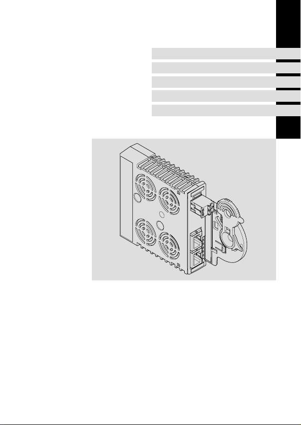
E94AYCET
Kommunikationsmodul
Communication module
Module de communication
Módulo de comunicaciones
Modulo di comunicazione
Page 2

Lesen Sie zuerst diese Anleitung, bevor Sie mit den Arbeiten beginnen!
Beachten Sie die enthaltenen Sicherheitshinweise.
Please read these instructions before you start working!
Follow the enclosed safety instructions.
Veuillez lire attentivement cette documentation avant toute action !
Les consignes de sécurité doivent impérativement être respectées.
Lea las instrucciones antes de empezar a trabajar.
Observe las instrucciones de seguridad indicadas.
Prima di usare l’apparecchiatura, leggere le istruzioni contenute in questo
manuale.
Osservare le note di sicurezza.
Page 3
E94AYCET001B
E94AYCET017
Page 4
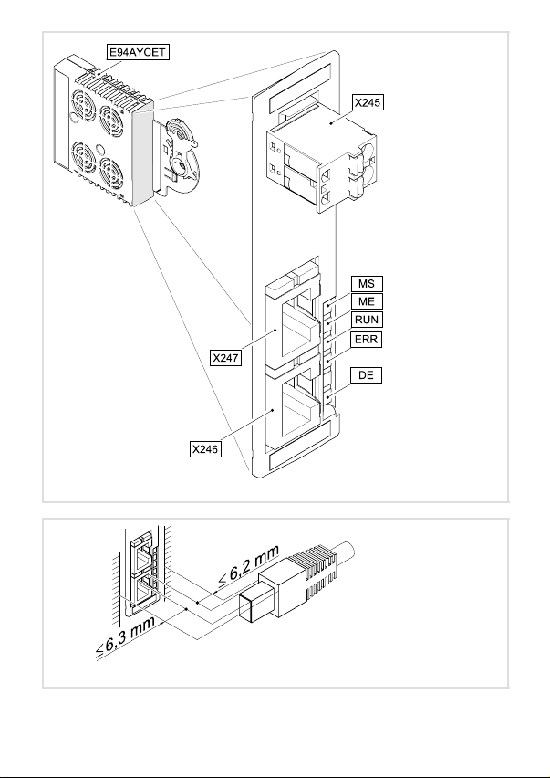
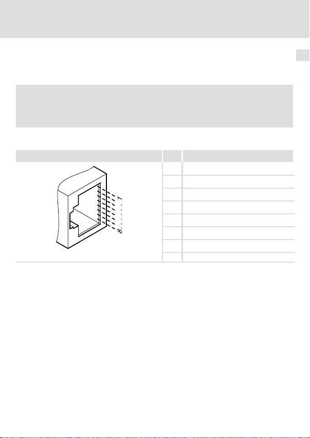
Legende zur Abbildung auf der Ausklappseite
Pos. Beschreibung Ausführliche
X245 Anschluss für externe Spannungsversorgung
l 2−polige Steckerleiste mit Federkraftanschluss
X246 EtherCAT−Anschluss, Eingang (IN)
l RJ45−Buchse nach IEC 60603−7
X247 EtherCAT−Anschluss, Ausgang (OUT)
l RJ45−Buchse nach IEC 60603−7
MS
ME
BS
LED−Statusanzeigen zur Diagnose
BE
DE
0Abb. 0Tab. 0
Information
19
17
17
21
4
EDK94AYCET DE/EN/FR/ES/IT 5.0
Page 5

Inhalt i
1 Über diese Dokumentation 6 . . . . . . . . . . . . . . . . . . . . . . . . . . . . . . . . . . . . . . . . . . . .
Verwendete Konventionen 7 . . . . . . . . . . . . . . . . . . . . . . . . . . . . . . . . . . . . . . . . . . . .
Verwendete Hinweise 8 . . . . . . . . . . . . . . . . . . . . . . . . . . . . . . . . . . . . . . . . . . . . . . . .
2 Sicherheitshinweise 10 . . . . . . . . . . . . . . . . . . . . . . . . . . . . . . . . . . . . . . . . . . . . . . . . . .
3 Produktbeschreibung 11 . . . . . . . . . . . . . . . . . . . . . . . . . . . . . . . . . . . . . . . . . . . . . . . .
Funktion 11 . . . . . . . . . . . . . . . . . . . . . . . . . . . . . . . . . . . . . . . . . . . . . . . . . . . . . . . . . . .
Bestimmungsgemäße Verwendung 11 . . . . . . . . . . . . . . . . . . . . . . . . . . . . . . . . . . . .
Lieferumfang 11 . . . . . . . . . . . . . . . . . . . . . . . . . . . . . . . . . . . . . . . . . . . . . . . . . . . . . . .
Identifikation 12 . . . . . . . . . . . . . . . . . . . . . . . . . . . . . . . . . . . . . . . . . . . . . . . . . . . . . . .
4 Technische Daten 13 . . . . . . . . . . . . . . . . . . . . . . . . . . . . . . . . . . . . . . . . . . . . . . . . . . . .
Allgemeine Daten 13 . . . . . . . . . . . . . . . . . . . . . . . . . . . . . . . . . . . . . . . . . . . . . . . . . . .
Abmessungen 14 . . . . . . . . . . . . . . . . . . . . . . . . . . . . . . . . . . . . . . . . . . . . . . . . . . . . . . .
5 Mechanische Installation 15 . . . . . . . . . . . . . . . . . . . . . . . . . . . . . . . . . . . . . . . . . . . . .
6 Elektrische Installation 16 . . . . . . . . . . . . . . . . . . . . . . . . . . . . . . . . . . . . . . . . . . . . . . .
EMV−gerechte Verdrahtung 16 . . . . . . . . . . . . . . . . . . . . . . . . . . . . . . . . . . . . . . . . . . .
EtherCAT−Anschluss 17 . . . . . . . . . . . . . . . . . . . . . . . . . . . . . . . . . . . . . . . . . . . . . . . . . .
Externe Spannungsversorgung 19 . . . . . . . . . . . . . . . . . . . . . . . . . . . . . . . . . . . . . . .
7 Inbetriebnahme 20 . . . . . . . . . . . . . . . . . . . . . . . . . . . . . . . . . . . . . . . . . . . . . . . . . . . . .
Vor dem ersten Einschalten 20 . . . . . . . . . . . . . . . . . . . . . . . . . . . . . . . . . . . . . . . . . . .
8 Diagnose 21 . . . . . . . . . . . . . . . . . . . . . . . . . . . . . . . . . . . . . . . . . . . . . . . . . . . . . . . . . . .
LED−Statusanzeigen 21 . . . . . . . . . . . . . . . . . . . . . . . . . . . . . . . . . . . . . . . . . . . . . . . . .
EDK94AYCET DE/EN/FR/ES/IT 5.0
5
Page 6

1 Über diese Dokumentation
1 Über diese Dokumentation
Inhalt
Diese Dokumentation enthält ...
ƒ Informationen zur mechanischen und elektrischen Installation des
Kommunikationsmoduls;
ƒ Sicherheitshinweise, die Sie unbedingt beachten müssen;
ƒ Angaben über Versionsstände der zu verwendenden Lenze Grundgeräte;
ƒ Informationen zu den LED−Statusanzeigen.
EtherCAT® ist eine eingetragene Marke und patentierte Technologie, lizenziert durch die
Beckhoff Automation GmbH, Deutschland.
Informationen zur Gültigkeit
Die Informationen in dieser Dokumentation sind gültig für folgende Geräte:
Kommunikationsmodul Typenbezeichnung ab Hardwarestand ab Softwarestand
EtherCAT E94AYCET VE 03.00
Zielgruppe
Diese Dokumentation richtet sich an Personen, die die Vernetzung und Fernwartung einer
Maschine projektieren, installieren, in Betrieb nehmen und warten.
Tipp!
Informationen und Hilfsmittel rund um die Lenze−Produkte finden Sie im
Download−Bereich unter
http://www.Lenze.com
6
EDK94AYCET DE/EN/FR/ES/IT 5.0
Page 7

Über diese Dokumentation
Verwendete Konventionen
Verwendete Konventionen
Diese Dokumentation verwendet folgende Konventionen zur Unterscheidung verschiedener Arten von Information:
Informationsart Auszeichnung Beispiele/Hinweise
Zahlenschreibweise
Dezimaltrennzeichen
Symbole
Seitenverweis
Punkt Es wird generell der Dezimalpunkt
verwendet.
Beispiel: 1234.56
Verweis auf eine andere Seite mit zusätzlichen Informationen
Beispiel: 16 = siehe Seite 16
1
EDK94AYCET DE/EN/FR/ES/IT 5.0
7
Page 8

1 Über diese Dokumentation
Verwendete Hinweise
Verwendete Hinweise
Um auf Gefahren und wichtige Informationen hinzuweisen, werden in dieser Dokumentation folgende Piktogramme und Signalwörter verwendet:
Sicherheitshinweise
Aufbau der Sicherheitshinweise:
Gefahr!
(kennzeichnet die Art und die Schwere der Gefahr)
Hinweistext
(beschreibt die Gefahr und gibt Hinweise, wie sie vermieden werden kann)
Piktogramm und Signalwort Bedeutung
Gefahr von Personenschäden durch gefährliche elektrische Spannung
Gefahr!
Gefahr!
Stop!
Hinweis auf eine unmittelbar drohende Gefahr, die den
Tod oder schwere Verletzungen zur Folge haben kann,
wenn nicht die entsprechenden Maßnahmen getroffen
werden.
Gefahr von Personenschäden durch eine allgemeine Gefahrenquelle
Hinweis auf eine unmittelbar drohende Gefahr, die den
Tod oder schwere Verletzungen zur Folge haben kann,
wenn nicht die entsprechenden Maßnahmen getroffen
werden.
Gefahr von Sachschäden
Hinweis auf eine mögliche Gefahr, die Sachschäden zur
Folge haben kann, wenn nicht die entsprechenden Maßnahmen getroffen werden.
8
EDK94AYCET DE/EN/FR/ES/IT 5.0
Page 9

Anwendungshinweise
Piktogramm und Signalwort Bedeutung
Über diese Dokumentation
Verwendete Hinweise
1
Hinweis!
Tipp!
Wichtiger Hinweis für die störungsfreie Funktion
Nützlicher Tipp für die einfache Handhabung
Verweis auf andere Dokumentation
EDK94AYCET DE/EN/FR/ES/IT 5.0
9
Page 10

2 Sicherheitshinweise
2 Sicherheitshinweise
Gefahr!
Unsachgemäßer Umgang mit dem Kommunikationsmodul und dem
Grundgerät kann schwere Personenschäden und Sachschäden verursachen.
Beachten Sie die in der Dokumentation zum Grundgerät enthaltenen
Sicherheitshinweise und Restgefahren.
Stop!
Elektrostatische Entladung
Durch elektrostatische Entladung können elektronische Bauteile innerhalb des
Kommunikationsmoduls beschädigt oder zerstört werden.
Mögliche Folgen:
ƒ Das Kommunikationsmodul ist defekt.
ƒ Die Feldbus−Kommunikation ist nicht möglich oder fehlerhaft.
Schutzmaßnahmen
ƒ Befreien Sie sich vor dem Berühren des Moduls von elektrostatischen
Aufladungen.
10
EDK94AYCET DE/EN/FR/ES/IT 5.0
Page 11

Produktbeschreibung
Funktion
3 Produktbeschreibung
Funktion
Das Kommunikationsmodul koppelt Lenze Servo Drives 9400 an das Kommunikationssystem EtherCAT.
Bestimmungsgemäße Verwendung
Das Kommunikationsmodul ...
ƒ ist eine Zubehör−Baugruppe, die mit folgenden Lenze Grundgeräten eingesetzt
werden kann:
Produktreihe Typenbezeichnung ab Hardwarestand ab Softwarestand
Servo Drives 9400 HighLine E94AxHxxxx VA 01.51
Servo Drives 9400 PLC E94AxPExxxx VA 02.00
Servo Drives 9400
Versorgungs− und Rückspeisemodul
ƒ ist ein Betriebsmittel zum Einsatz in industriellen Starkstromanlagen.
ƒ nur in EtherCAT−Netzwerken einsetzen.
Jede andere Verwendung gilt als sachwidrig!
E94ARNxxxx VA 01.00
Lieferumfang
ƒ Kommunikationsmodul E94AYCET (EtherCAT)
ƒ Montageanleitung
Tipp!
Weiterführende Informationen zu diesem Kommunikationsmodul finden Sie
im entsprechenden Kommunikationshandbuch.
Die PDF−Datei finden Sie im Download−Bereich unter
http://www.Lenze.com
3
EDK94AYCET DE/EN/FR/ES/IT 5.0
11
Page 12
3 Produktbeschreibung
Identifikation
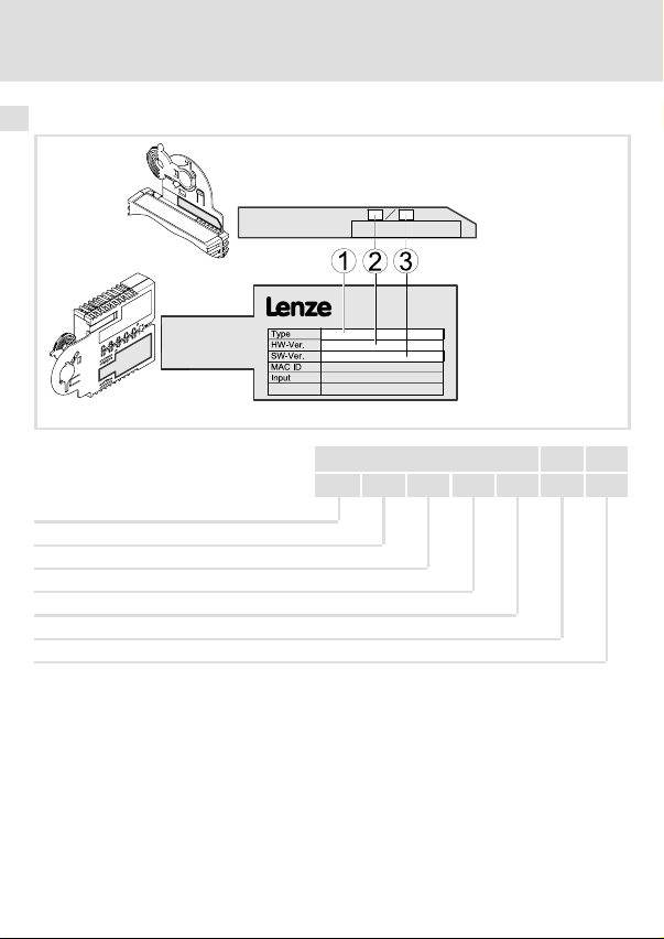
Identifikation
Produktreihe
Gerätegeneration
Modulkennung: Erweiterungsmodul
Modultyp: Kommunikationsmodul
EtherCAT
Hardwarestand
Softwarestand
E94AYCET005
E94 A Y C ET VE 03.00
12
EDK94AYCET DE/EN/FR/ES/IT 5.0
Page 13
Technische Daten
Allgemeine Daten
4 Technische Daten
Allgemeine Daten
Bereich Werte
Bestell−Bezeichnung E94AYCET
Kommunikationsprofil EtherCAT
Kommunikationsmedium S/FTP (Screened Foiled Twisted Pair, ISO/IEC 11801 oder EN 50173),
Schnittstelle RJ45: Standard Ethernet (nach IEEE 802.3), 100Base−TX (Fast Ether-
Netzwerktopologie Linie, Switch
Teilnehmeranzahl max. 65535 (im gesamten Netz)
Max. Leitungslänge zwischen
zwei EtherCAT−Teilnehmern
Teilnehmertyp EtherCAT−Slave
Vendor−ID 0x3B
Übertragungsrate 100 MBit/s, vollduplex
Zykluszeiten 1 ms oder ein ganzzahliges Vielfaches von 1 ms, max. 15 ms bei
Spannungsversorgung Externe Versorgung über separates Netzteil
Konformitäten, Approbationen
CAT 5e
net)
100 m (typisch)
hex
Verwendung von "Distributed clocks" (DC)
l "+": U = 24 V DC (20.4V−0% ... 28.8V+0%), I = 130 mA
l "−": Bezugspotenzial für externe Spannungsversorgung
l CE
l UL
Gerätehandbuch "Servo Drives 9400"
Hier finden Sie die Umgebungsbedingungen und Daten zur
Elektromagnetischen Verträglichkeit (EMV), die auch für das
Kommunikationsmodul gelten.
4
EDK94AYCET DE/EN/FR/ES/IT 5.0
13
Page 14
4 Technische Daten
Abmessungen
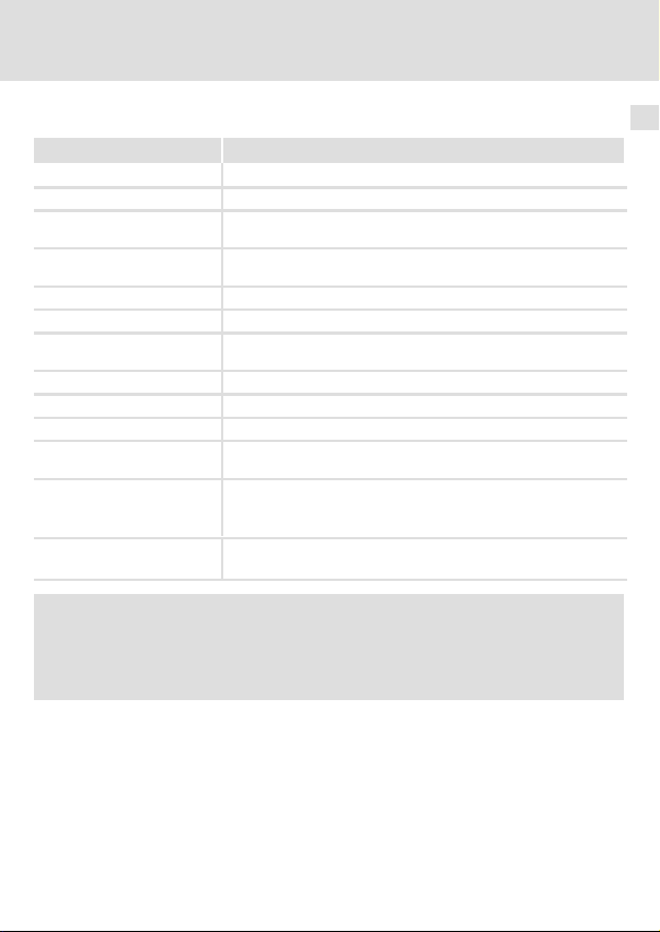
Abmessungen
a89 mm
b 134 mm
b1 87 mm
e 23 mm
E94YCXX005
14
EDK94AYCET DE/EN/FR/ES/IT 5.0
Page 15
5 Mechanische Installation
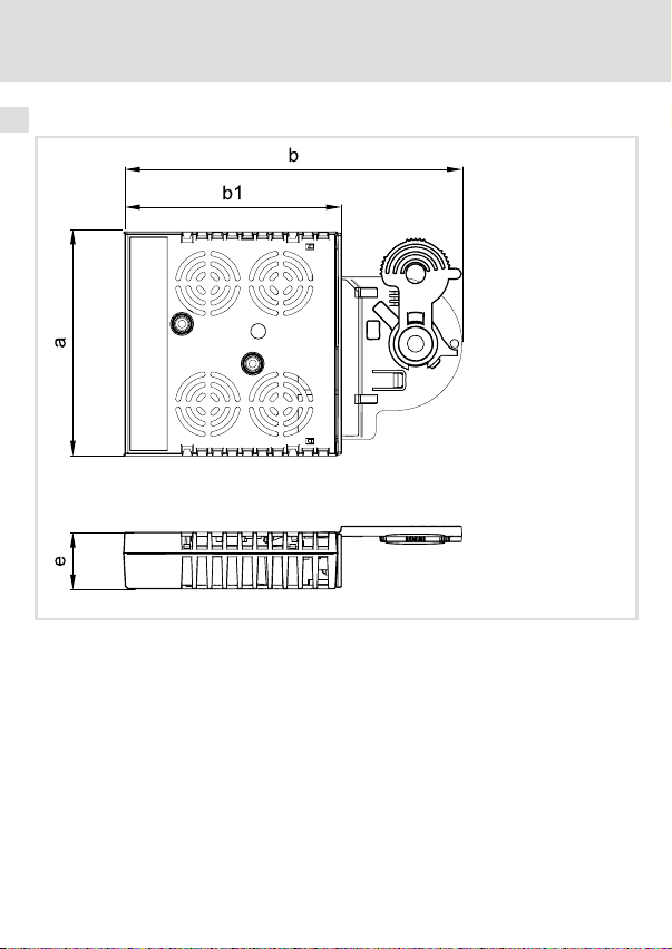
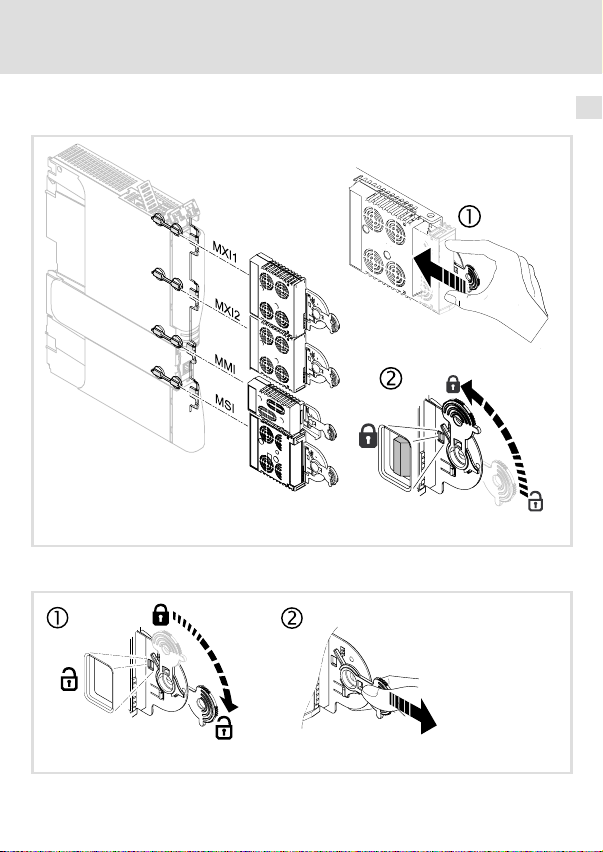
Montage
Demontage
Mechanische Installation 5
E94YCXX001G
EDK94AYCET DE/EN/FR/ES/IT 5.0
E94AYCXX001H
15
Page 16
6 Elektrische Installation
EMV−gerechte Verdrahtung
6 Elektrische Installation
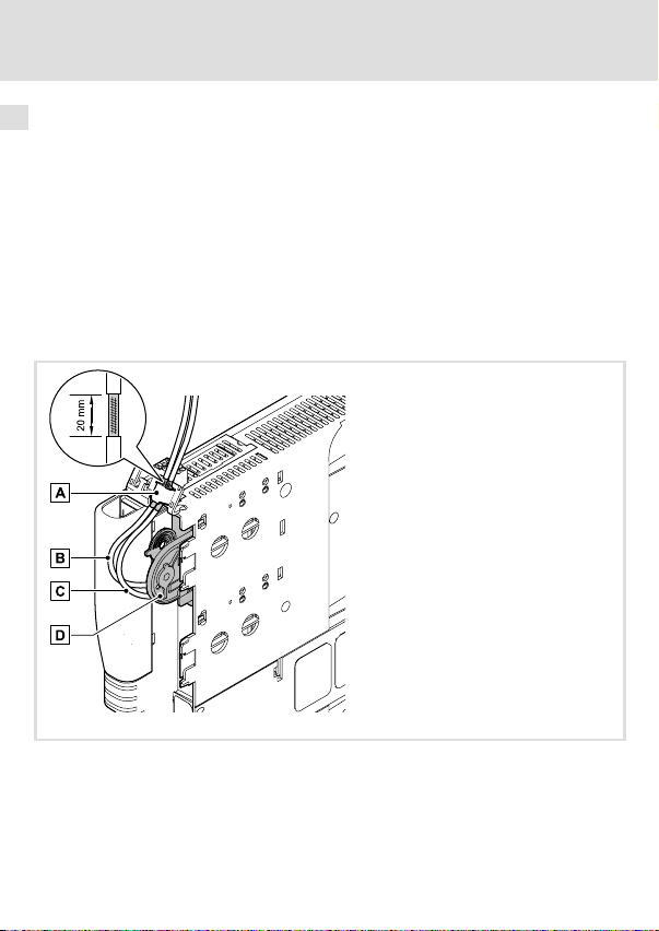
EMV−gerechte Verdrahtung
In typischen Anlagen ist die standardmäßige Schirmung der Ethernet−Kabel ausreichend.
In sehr stark gestörten Umgebungen kann eine Verbesserung der EMV−Festigkeit durch
eine zusätzliche beidseitige Erdung des Kabelschirms ermöglicht werden.
Beachten Sie dazu folgende Hinweise:
1. Der Abstand der zusätzlichen Erdung vom Ethernet−Stecker ist abhängig vom
Steckplatz des Moduls. Der Abstand beträgt
– ca. 10 cm für den oberen Steckplatz (MXI1);
– ca. 20 cm für den unteren Steckplatz (MXI2).
2. Entfernen Sie ausgehend von diesem Abstand die Kunststoffumhüllung des Kabels
auf einer Länge von 2 cm.
3. Befestigen Sie den Kabelschirm am Schirmblech des Servo Drive 9400.
Befestigung am Schirmblech des Servo Drive 9400
Weiterführende EtherCAT−Leitung an X247 (OUT)
Ankommende EtherCAT−Leitung an X246 (IN)
Kommunikationsmodul in Steckplatz MXI1 des Servo Drive 9400
16
E94YCXX008
EDK94AYCET DE/EN/FR/ES/IT 5.0
Page 17
Elektrische Installation
EtherCAT−Anschluss
EtherCAT−Anschluss
Zum Anschluss an das Kommunikationsmodul eignet sich ein handelsübliches Standard−
Ethernet−Patchkabel (siehe "Spezifikation des Ethernet−Kabels" (18)).
Hinweis!
Um Beschädigungen der RJ45−Buchse zu vermeiden, den Stecker des
Ethernet−Kabels senkrecht in die Buchse stecken bzw. aus der Buchse ziehen.
Pinbelegung
RJ45−Buchse Pin Signal
1 Tx +
2 Tx −
3 Rx +
4 −
5 −
6 Rx−
7 −
E94AYCXX004C
8 −
Tipp!
Die EtherCAT−Schnittstellen verfügen über eine Auto−MDIX−Funktion. Diese
Funktion passt die Polung der RJ45−Schnittstellen so an, dass unabhängig von
der Polung der gegenüberliegenden EtherCAT−Schnittstelle und dem
verwendeten Kabeltyp (Standard−Patch−Kabel oder Cross−Over−Kabel) eine
Verbindung hergestellt wird.
6
EDK94AYCET DE/EN/FR/ES/IT 5.0
17
Page 18
6 Elektrische Installation
EtherCAT−Anschluss
Spezifikation des Ethernet−Kabels
Hinweis!
Verwenden Sie ausschließlich Kabel, die den aufgeführten Spezifikationen
entsprechen.
Spezifikation des Ethernet−Kabels
Ethernet−Standard Standard Ethernet (nach IEEE 802.3), 100Base−TX (Fast Ethernet)
Kabeltyp S/FTP (Screened Foiled Twisted Pair, ISO/IEC 11801 oder
Dämpfung 23.2 dB (bei 100 MHz und je 100 m)
Nebensprechdämpfung 24 dB (bei 100 MHz und je 100 m)
Rückflussdämpfung 10 dB (je 100 m)
Wellenwiderstand
EN 50173), CAT 5e
100 W
18
EDK94AYCET DE/EN/FR/ES/IT 5.0
Page 19
Elektrische Installation
Externe Spannungsversorgung
Externe Spannungsversorgung
Hinweis!
Verwenden Sie bei externer Spannungsversorgung und bei größeren
Entfernungen zwischen den Schaltschränken in jedem Schaltschrank immer
ein separates und nach EN 61800−5−1 sicher getrenntes Netzteil
("SELV"/"PELV").
Die externe Spannungsversorgung des Kommunikationsmoduls ist notwendig, wenn beim
Ausfall der Versorgung des Grundgerätes die EtherCAT−Kommunikation bestehen bleiben
soll.
Versorgen das Kommunikationsmodul über die 2−polige Steckerleiste (X245) mit einer separaten Versorgungsspannung.
Bezeichnung Beschreibung
+ Externe Spannungsversorgung
− Bezugspotenzial für externe Spannungsversorgung
Daten der Anschlussklemmen
Bereich Werte
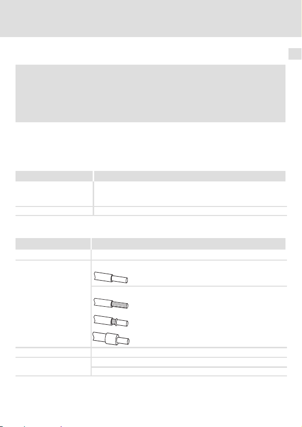
Elektrischer Anschluss 2−polige Steckerleiste (Federkraftanschluss/Schraubanschluss)
Anschlussmöglichkeiten
Anzugsmoment 0.5 ... 0.6 Nm / 4.4 ... 5.3 lb−in (nur bei Schraubanschluss)
Abisolierlänge
U = 24VDC(20.4 V − 0%... 28.8 V + 0%)
I = 130 mA
starr:
flexibel:
6 mm bei Schraubanschluss
9 mm bei Federkraftanschluss
2
1.5 mm
(AWG 16)
ohne Aderendhülse
2
1.5 mm
(AWG 16)
mit Aderendhülse, ohne Kunststoffhülse
2
(AWG 16)
1.5 mm
mit Aderendhülse, mit Kunststoffhülse
2
(AWG 20)
0.5 mm
6
EDK94AYCET DE/EN/FR/ES/IT 5.0
19
Page 20

7 Inbetriebnahme
Vor dem ersten Einschalten
7 Inbetriebnahme
Vor dem ersten Einschalten
Stop!
Bevor Sie das Grundgerät mit dem Kommunikationsmodul erstmalig
einschalten, überprüfen Sie die gesamte Verdrahtung auf Vollständigkeit,
Kurzschluss und Erdschluss.
Kommunikationshandbuch E94AYCET (EtherCAT)
Hier finden Sie ausführliche Informationen zur Inbetriebnahme des
Kommunikationsmoduls.
20
EDK94AYCET DE/EN/FR/ES/IT 5.0
Page 21
Diagnose
LED−Statusanzeigen
8 Diagnose
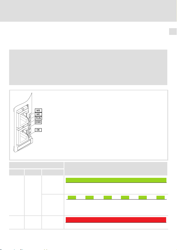
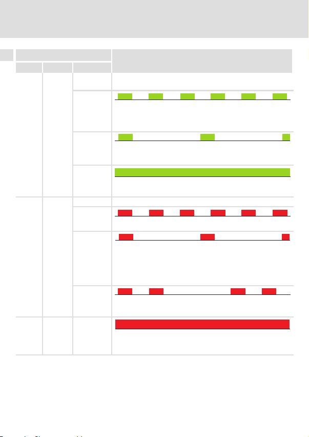
LED−Statusanzeigen
Zur Störungsdiagnose stehen für das EtherCAT−Modul die auf der Frontseite angeordneten
LEDs zur Verfügung.
Hinweis!
Im normalen Betrieb ...
ƒ sollten nur die LEDs "MS" und "BS" permanent leuchten.
ƒ muss an den RJ45−Buchsen X246 und X247 jeweils die grüne LED leuchten
oder blinken.
E94YCET001E
LED
Pos. Farbe Zustand
MS grün an
blinkt
ME rot an
Beschreibung
Das Kommunikationsmodul ist mit Spannung versorgt und hat
eine Verbindung zum Grundgerät.
200 ms
200 ms
Das Kommunikationsmodul ist mit Spannung versorgt, hat aber
keine Verbindung zum Grundgerät. (Grundgerät ist ausgeschaltet, in der Initialisierungsphase oder nicht vorhanden.)
Ein Fehler liegt im Bereich des Kommunikationsmoduls vor.
8
EDK94AYCET DE/EN/FR/ES/IT 5.0
21
Page 22
8 Diagnose
LED−Statusanzeigen
LED
RUN grün
ERR rot
DE rot an
ZustandFarbePos.
aus Das Kommunikationsmodul ist am Feldbus nicht aktiv oder befin-
blinkt
blinkt 1−mal
(single
flash)
Beschreibung
Beschreibung
det sich im Zustand "Init".
200 ms
200 ms
Zustand "Pre−Operational" aktiv:
l Zugriff auf Parameter und Objekte möglich.
l Kein Prozessdatenaustausch
200 ms
Zustand "Safe−Operational" aktiv:
l Die Daten sind im Grundgerät noch nicht aktiv.
1000 ms
200 ms
1000 ms
an
Das Kommunikationsmodul befindet sich im Zustand
"Operational".
aus Kein Fehler
blinkt
200 ms
200 ms
Die Konfiguration ist ungültig/fehlerhaft.
blinkt 1−mal
(single
flash)
blinkt 2−mal
(double
flash)
200 ms
l Ein nicht angeforderter Zustandswechsel ist aufgetreten. (Die
Slave−Applikation hat selbständig den EtherCAT−Status geändert.)
l Synchronisationsfehler (Der EtherCAT−Teilnehmer geht auto-
matisch in den Zustand "Safe−Operational".)
200 ms
Ein "Application Watchdog Timeout" oder ein "Sync Manager
Watchdog Timeout" ist aufgetreten.
Das Kommunikationsmodul wird vom Grundgerät nicht akzep-
tiert oder das Grundgerät ist nicht aktiv. (Siehe Hinweise in der
Dokumentation zum Grundgerät.)
200 ms
200 ms
1000 ms
1000 ms
200 ms
200 ms
1000 ms
200 ms
200 ms
22
EDK94AYCET DE/EN/FR/ES/IT 5.0
Page 23
LED
Pos. Farbe Zustand
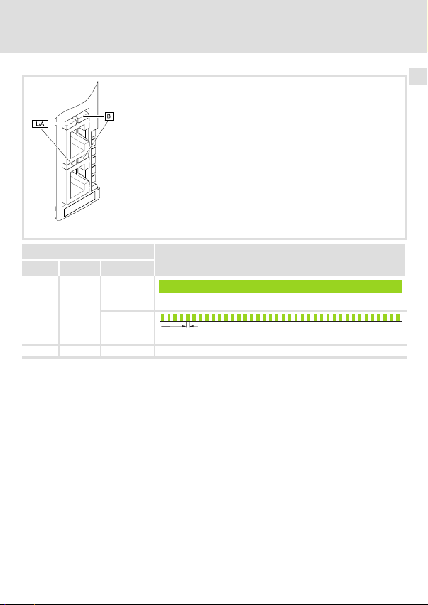
L/A grün an
flackert
B rot aus Diese LED wird nicht verwendet.
Beschreibung
Physikalische EtherCAT−Verbindung ist vorhanden.
50ms
Daten werden über EtherCAT ausgetauscht.
Diagnose
LED−Statusanzeigen
E94YCET001E
8
EDK94AYCET DE/EN/FR/ES/IT 5.0
23
Page 24
Legend for fold−out page
Pos. Description Detailed
X245 Terminal for external voltage supply
l 2−pin plug connector with spring connection
X246 EtherCAT connection, input (IN)
l RJ45 socket in accordance with IEC 60603−7
X247 EtherCAT connection, output (OUT)
l RJ45 socket in accordance with IEC 60603−7
MS
ME
BS
LED status displays for diagnostics
BE
DE
0Fig. 0Tab. 0
information
39
37
37
41
24
EDK94AYCET DE/EN/FR/ES/IT 5.0
Page 25

Contents i
1 About this documentation 26 . . . . . . . . . . . . . . . . . . . . . . . . . . . . . . . . . . . . . . . . . . . .
Conventions used 27 . . . . . . . . . . . . . . . . . . . . . . . . . . . . . . . . . . . . . . . . . . . . . . . . . . . .
Notes used 28 . . . . . . . . . . . . . . . . . . . . . . . . . . . . . . . . . . . . . . . . . . . . . . . . . . . . . . . . .
2 Safety instructions 30 . . . . . . . . . . . . . . . . . . . . . . . . . . . . . . . . . . . . . . . . . . . . . . . . . . .
3 Product description 31 . . . . . . . . . . . . . . . . . . . . . . . . . . . . . . . . . . . . . . . . . . . . . . . . . .
Function 31 . . . . . . . . . . . . . . . . . . . . . . . . . . . . . . . . . . . . . . . . . . . . . . . . . . . . . . . . . . .
Application as directed 31 . . . . . . . . . . . . . . . . . . . . . . . . . . . . . . . . . . . . . . . . . . . . . . .
Scope of supply 31 . . . . . . . . . . . . . . . . . . . . . . . . . . . . . . . . . . . . . . . . . . . . . . . . . . . . . .
Identification 32 . . . . . . . . . . . . . . . . . . . . . . . . . . . . . . . . . . . . . . . . . . . . . . . . . . . . . . .
4 Technical data 33 . . . . . . . . . . . . . . . . . . . . . . . . . . . . . . . . . . . . . . . . . . . . . . . . . . . . . . .
General data 33 . . . . . . . . . . . . . . . . . . . . . . . . . . . . . . . . . . . . . . . . . . . . . . . . . . . . . . .
Dimensions 34 . . . . . . . . . . . . . . . . . . . . . . . . . . . . . . . . . . . . . . . . . . . . . . . . . . . . . . . . .
5 Mechanical installation 35 . . . . . . . . . . . . . . . . . . . . . . . . . . . . . . . . . . . . . . . . . . . . . . .
6 Electrical installation 36 . . . . . . . . . . . . . . . . . . . . . . . . . . . . . . . . . . . . . . . . . . . . . . . . .
Wiring according to EMC 36 . . . . . . . . . . . . . . . . . . . . . . . . . . . . . . . . . . . . . . . . . . . . . .
EtherCAT connection 37 . . . . . . . . . . . . . . . . . . . . . . . . . . . . . . . . . . . . . . . . . . . . . . . . .
External voltage supply 39 . . . . . . . . . . . . . . . . . . . . . . . . . . . . . . . . . . . . . . . . . . . . . .
7 Commissioning 40 . . . . . . . . . . . . . . . . . . . . . . . . . . . . . . . . . . . . . . . . . . . . . . . . . . . . .
Before switching on 40 . . . . . . . . . . . . . . . . . . . . . . . . . . . . . . . . . . . . . . . . . . . . . . . . .
8 Diagnostics 41 . . . . . . . . . . . . . . . . . . . . . . . . . . . . . . . . . . . . . . . . . . . . . . . . . . . . . . . . .
LED status displays 41 . . . . . . . . . . . . . . . . . . . . . . . . . . . . . . . . . . . . . . . . . . . . . . . . . .
EDK94AYCET DE/EN/FR/ES/IT 5.0
25
Page 26

1 About this documentation
1 About this documentation
Contents
This documentation contains ...
ƒ information on the mechanical and electrical installation of the communication
module;
ƒ safety instructions which must be observed by all means;
ƒ information about versions of the Lenze standard devices to be used;
ƒ Information on the LED status displays.
EtherCAT® is a registered trademark and patented technology, licensed by Beckhoff
Automation GmbH, Germany.
Validity information
The information given in this documentation is valid for the following devices:
Communication
module
EtherCAT E94AYCET VE 03.00
Target group
This documentation addresses to persons who project, install, commission, and maintain
the networking and remote maintenance of a machine.
Type designation From hardware version From software version
Tip!
Information and auxiliary devices around the Lenze products can be found in
the download area at
http://www.Lenze.com
26
EDK94AYCET DE/EN/FR/ES/IT 5.0
Page 27

About this documentation
Conventions used
Conventions used
This documentation uses the following conventions to distinguish between different types
of information:
Type of information Identification Examples/notes
Numbers
Decimal separator
Symbols
Page reference
Point The decimal point is used throughout
this documentation.
Example: 1234.56
Reference to another page with
additional information
Example: 16 = see page 16
1
EDK94AYCET DE/EN/FR/ES/IT 5.0
27
Page 28

1 About this documentation
Notes used
Notes used
The following pictographs and signal words are used in this documentation to indicate
dangers and important information:
Safety instructions
Structure of safety instructions:
Danger!
(characterises the type and severity of danger)
Note
(describes the danger and gives information about how to prevent dangerous
situations)
Pictograph and signal word Meaning
Danger of personal injury through dangerous electrical
voltage.
Danger!
Danger!
Stop!
Reference to an imminent danger that may result in
death or serious personal injury if the corresponding
measures are not taken.
Danger of personal injury through a general source of
danger.
Reference to an imminent danger that may result in
death or serious personal injury if the corresponding
measures are not taken.
Danger of property damage.
Reference to a possible danger that may result in
property damage if the corresponding measures are not
taken.
28
EDK94AYCET DE/EN/FR/ES/IT 5.0
Page 29

Application notes
Pictograph and signal word Meaning
About this documentation
Notes used
1
Note!
Tip!
Important note to ensure troublefree operation
Useful tip for simple handling
Reference to another documentation
EDK94AYCET DE/EN/FR/ES/IT 5.0
29
Page 30

2 Safety instructions
2 Safety instructions
Danger!
Inappropriate handling of the communication module and the standard device
can cause serious personal injury and material damage.
Observe the safety instructions and residual hazards described in the
documentation for the standard device.
Stop!
Electrostatic discharge
Electronic components of the communication module can be damaged or
destroyed through electrostatic discharge.
Possible consequences:
ƒ The communication module is damaged.
ƒ Fieldbus communication is not possible or faulty.
Protective measures
ƒ Discharge electrostatic charges before touching the module.
30
EDK94AYCET DE/EN/FR/ES/IT 5.0
Page 31

Product description
Function
3 Product description
Function
The communication module couples Lenze Servo Drives 9400 with the EtherCAT
communication system.
Application as directed
The communication module ...
ƒ is an accessory module which can be used in conjunction with the following Lenze
standard devices:
Product range Type designation From hardware
Servo Drives 9400 HighLine E94AxHxxxx VA 01.51
Servo Drives 9400 PLC E94AxPExxxx VA 02.00
Servo Drives 9400
Regenerative power supply
module
ƒ is a device to be used in industrial power systems.
ƒ is only to be used in EtherCAT networks.
Any other use shall be deemed inappropriate!
E94ARNxxxx VA 01.00
version
From software
version
Scope of supply
ƒ E94AYCET communication module (EtherCAT)
ƒ Mounting Instructions
Tip!
Further information regarding this communication module can be found in
the corresponding communication manual.
The PDF file can be found in the download area at
http://www.Lenze.com
3
EDK94AYCET DE/EN/FR/ES/IT 5.0
31
Page 32

3 Product description
Identification
Identification
Product range
Version
Module ID: extension module
Module type: communication module
EtherCAT
Hardware version
Software version
E94AYCET005
E94 A Y C ET VE 03.00
32
EDK94AYCET DE/EN/FR/ES/IT 5.0
Page 33

Technical data
General data
4 Technical data
General data
Field Values
Order designation E94AYCET
Communication profile EtherCAT
Communication medium S/FTP (Screened Foiled Twisted Pair, ISO/IEC 11801 or EN 50173),
Interface RJ45: Standard Ethernet (in accordance with IEEE 802.3), 100base−TX
Network topology Line, switch
Number of nodes Max. 65535 (in the entire network)
Max. cable length between
two EtherCAT nodes
Node type EtherCAT slave
Vendor ID 0x3B
Baud rate 100 Mbps, full duplex
Cycle times 1 ms or an integer multiple of 1 ms, max. 15 ms if "Distributed
Voltage supply External supply via separate power supply unit
Conformities, approvals
CAT 5e
(fast Ethernet)
100 m (typical)
hex
clocks" (DC) are used
l "+": U = 24 V DC (20.4V−0% ... 28.8V+0%), I = 130 mA
l "−": reference potential for external voltage supply
l CE
l UL
"Servo Drives 9400" hardware manual
Here you can find the ambient conditions and the electromagnetic
compatibility (EMC) specifications applying to the communication module.
4
EDK94AYCET DE/EN/FR/ES/IT 5.0
33
Page 34

4 Technical data
Dimensions
Dimensions
a89 mm
b 134 mm
b1 87 mm
e 23 mm
E94YCXX005
34
EDK94AYCET DE/EN/FR/ES/IT 5.0
Page 35

5 Mechanical installation
Mounting
Dismounting
Mechanical installation 5
E94YCXX001G
EDK94AYCET DE/EN/FR/ES/IT 5.0
E94AYCXX001H
35
Page 36

6 Electrical installation
Wiring according to EMC
6 Electrical installation
Wiring according to EMC
In typical systems, standard shielding of the Ethernet cables is sufficient.
In environments with a very high level of interference, immunity to noise can be improved
by additionally earthing the cable shield on both sides.
Observe the following notes for this:
1. The clearance of the additional earthing from the Ethernet plug depends on the
module slot. The clearance is
– approx. 10 cm for the upper slot (MXI1);
– approx. 20 cm for the lower slot (MXI2).
2. Starting from this clearance, remove the plastic sheath of the cable on a length of
2 cm.
3. Mount the cable shield on the shield sheet of the Servo Drive 9400.
Connection to the shield sheet of the Servo Drive 9400
Continuing EtherCAT cable at X247 (OUT)
Incoming EtherCAT cable at X246 (IN)
Communication module in slot MXI1 of the Servo Drive 9400
36
E94YCXX008
EDK94AYCET DE/EN/FR/ES/IT 5.0
Page 37

Electrical installation
EtherCAT connection
EtherCAT connection
You can use a standard Ethernet patch cable for connection to the communication module
(see "Ethernet cable specifications" (38)).
Note!
Plug/remove the Ethernet cable plug vertically into/from the socket to make
sure that the RJ45 socket will not be damaged.
Pin assignment
RJ45 socket PIN Signal
1 Tx +
2 Tx −
3 Rx +
4 −
5 −
6 Rx −
7 −
E94AYCXX004C
8 −
Tip!
The EtherCAT interfaces are equipped with an auto−MDIX function. This
function adapts the polarity of the RJ45 interfaces such that independently of
the polarity of the opposite EtherCAT interface and the cable type used
(standard patch cable or crossover cable) a connection is established.
6
EDK94AYCET DE/EN/FR/ES/IT 5.0
37
Page 38

6 Electrical installation
EtherCAT connection
Ethernet cable specifications
Note!
Only use cables complying with the below specifications.
Specification of the Ethernet cable
Ethernet standard Standard Ethernet (in accordance with IEEE 802.3), 100Base−TX
Cable type S/FTP (Screened Foiled Twisted Pair, ISO/IEC 11801 or EN 50173),
Damping 23.2 dB (at 100 MHz and per 100 m)
Crosstalk damping 24 dB (at 100 MHz and per 100 m)
Return loss 10 dB (per 100 m)
Surge impedance
(Fast Ethernet)
CAT 5e
100 W
38
EDK94AYCET DE/EN/FR/ES/IT 5.0
Page 39

Electrical installation
External voltage supply
External voltage supply
Note!
Always use a separate power supply unit in every control cabinet and safely
separate it according to EN 61800−5−1 ("SELV"/"PELV") in the case of external
voltage supply and larger distances between the control cabinets.
The external voltage supply of the communication module is required if EtherCAT
communication is to remain intact in case the supply of the standard device fails.
Supply the communication module via the 2−pole plug connector (X245) with a separate
supply voltage.
Designation Description
+ External voltage supply
− Reference potential for external voltage supply
Terminal data
Field Values
Electrical connection 2−pin plug connector (spring connection/screw connection)
Possible connections
Tightening torque 0.5 ... 0.6 Nm / 4.4 ... 5.3 lb−in (only for screw connection)
Stripping length
U = 24VDC(20.4 V − 0%... 28.8 V + 0%)
I = 130 mA
rigid:
flexible:
6 mm for screw connection
9 mm for spring connection
2
1.5 mm
(AWG 16)
without wire end ferrule
2
(AWG 16)
1.5 mm
with wire end ferrule, without plastic sleeve
2
(AWG 16)
1.5 mm
with wire end ferrule, with plastic sleeve
2
(AWG 20)
0.5 mm
6
EDK94AYCET DE/EN/FR/ES/IT 5.0
39
Page 40

7 Commissioning
Before switching on
7 Commissioning
Before switching on
Stop!
Before switching on the standard device with the communication module for
the first time, check the entire wiring for completeness, short circuit and earth
fault.
E94AYCET (EtherCAT) communication manual
Here you’ll find some detailed information on commissioning the
communication module.
40
EDK94AYCET DE/EN/FR/ES/IT 5.0
Page 41

Diagnostics
LED status displays
8 Diagnostics
LED status displays
For fault diagnostics the LEDs on the front are provided for the EtherCAT module.
Note!
During normal operation ...
ƒ only the LEDs "MS" and "BS" should be lit constantly.
ƒ The green LED at the RJ45 sockets X246 and X247 must be lit or blinking.
E94YCET001E
LED
Pos. Colour Condition
MS green on
blinking
ME red on
Description
The communication module is supplied with voltage and has a
connection to the standard device.
200 ms
200 ms
The communication module is supplied with voltage but has no
connection to the standard device (standard device is either
switched off, in the initialisation phase, or not available).
An error in the communication module has occurred.
8
EDK94AYCET DE/EN/FR/ES/IT 5.0
41
Page 42

8 Diagnostics
LED status displays
LED
RUN green
ERR red
DE red on
ConditionColourPos.
off The communication module is not active on the fieldbus or is in
blinking
blinking
once
(single
flash)
Description
Description
the "Init" status.
200 ms
200 ms
"Pre−operational" status active:
l Access to parameters and objects possible.
l No process data exchange
200 ms
"Safe−operational" status active:
l The data are not active in the standard device yet.
1000 ms
200 ms
1000 ms
on
The communication module is in the "Operational" status.
off No error
blinking
200 ms
200 ms
The configuration is invalid/faulty.
blinking
once
(single
flash)
blinking
twice
(double
flash)
200 ms
l A state change that was not requested has occurred. (The
slave application has changed the EtherCAT status
independently.)
l Synchronisation error (The EtherCAT node changes to the
"Safe−operational" status automatically.)
200 ms
An "Application Watchdog Timeout" or a "Sync Manager
Watchdog Timeout" has occurred.
The communication module is not accepted by the standard
device, or the standard device is not active. (See notes in the
documentation for the standard device.)
200 ms
200 ms
1000 ms
1000 ms
200 ms
200 ms
1000 ms
200 ms
200 ms
42
EDK94AYCET DE/EN/FR/ES/IT 5.0
Page 43

LED
Pos. Colour Condition
L/A green on
flickering
B red off This LED is not used.
Description
Physical EtherCAT connection is available.
50ms
Data are exchanged via EtherCAT.
Diagnostics
LED status displays
E94YCET001E
8
EDK94AYCET DE/EN/FR/ES/IT 5.0
43
Page 44

Légende de l’illustration de la page dépliante
Pos. Description Informations
X245 Raccordement pour alimentation externe
l Bornier à lame ressort, à 2 broches
X246 Raccordement EtherCAT, entrée (IN)
l Prise RJ45 selon CEI 60603−7
X247 Raccordement EtherCAT, sortie (OUT)
l Prise RJ45 selon CEI 60603−7
MS
ME
BS
Affichage d’état par LED pour le diagnostic
BE
DE
0Fig. 0Tab. 0
détaillées
59
57
57
61
44
EDK94AYCET DE/EN/FR/ES/IT 5.0
Page 45

Sommaire i
1 Présentation du document 46 . . . . . . . . . . . . . . . . . . . . . . . . . . . . . . . . . . . . . . . . . . . .
Conventions utilisées 47 . . . . . . . . . . . . . . . . . . . . . . . . . . . . . . . . . . . . . . . . . . . . . . . . .
Consignes utilisées 48 . . . . . . . . . . . . . . . . . . . . . . . . . . . . . . . . . . . . . . . . . . . . . . . . . . .
2 Consignes de sécurité 50 . . . . . . . . . . . . . . . . . . . . . . . . . . . . . . . . . . . . . . . . . . . . . . . .
3 Description du produit 51 . . . . . . . . . . . . . . . . . . . . . . . . . . . . . . . . . . . . . . . . . . . . . . . .
Fonction 51 . . . . . . . . . . . . . . . . . . . . . . . . . . . . . . . . . . . . . . . . . . . . . . . . . . . . . . . . . . .
Utilisation conforme à la fonction 51 . . . . . . . . . . . . . . . . . . . . . . . . . . . . . . . . . . . . . .
Equipement livré 51 . . . . . . . . . . . . . . . . . . . . . . . . . . . . . . . . . . . . . . . . . . . . . . . . . . . .
Identification 52 . . . . . . . . . . . . . . . . . . . . . . . . . . . . . . . . . . . . . . . . . . . . . . . . . . . . . . .
4 Spécifications techniques 53 . . . . . . . . . . . . . . . . . . . . . . . . . . . . . . . . . . . . . . . . . . . . .
Caractéristiques générales 53 . . . . . . . . . . . . . . . . . . . . . . . . . . . . . . . . . . . . . . . . . . . .
Encombrements 54 . . . . . . . . . . . . . . . . . . . . . . . . . . . . . . . . . . . . . . . . . . . . . . . . . . . . .
5 Installation mécanique 55 . . . . . . . . . . . . . . . . . . . . . . . . . . . . . . . . . . . . . . . . . . . . . . .
6 Installation électrique 56 . . . . . . . . . . . . . . . . . . . . . . . . . . . . . . . . . . . . . . . . . . . . . . . .
Câblage conforme CEM 56 . . . . . . . . . . . . . . . . . . . . . . . . . . . . . . . . . . . . . . . . . . . . . . .
Raccordement EtherCAT 57 . . . . . . . . . . . . . . . . . . . . . . . . . . . . . . . . . . . . . . . . . . . . . .
Alimentation externe 59 . . . . . . . . . . . . . . . . . . . . . . . . . . . . . . . . . . . . . . . . . . . . . . . .
7 Mise en service 60 . . . . . . . . . . . . . . . . . . . . . . . . . . . . . . . . . . . . . . . . . . . . . . . . . . . . . .
Avant la première mise sous tension 60 . . . . . . . . . . . . . . . . . . . . . . . . . . . . . . . . . . . .
8 Diagnostic 61 . . . . . . . . . . . . . . . . . . . . . . . . . . . . . . . . . . . . . . . . . . . . . . . . . . . . . . . . . .
Affichages d’état par LED 61 . . . . . . . . . . . . . . . . . . . . . . . . . . . . . . . . . . . . . . . . . . . . .
EDK94AYCET DE/EN/FR/ES/IT 5.0
45
Page 46

1 Présentation du document
1 Présentation du document
Contenu
Ce document contient ...
ƒ des informations sur l’installation mécanique et électrique du module de
communication ;
ƒ des consignes de sécurité qui doivent impérativement être respectées ;
ƒ des indications sur les versions des appareils de base Lenze à utiliser ;
ƒ des informations sur les affichages d’état par LED.
EtherCAT® est une marque déposée et une technologie brevetée sous licence de Beckhoff
Automation GmbH, Allemagne.
Validité
Les informations contenues dans le présent document s’appliquent aux appareils suivants :
Module de
communication
EtherCAT E94AYCET VE 03.00
Public visé
Ce document s’adresse aux personnes chargées de la conception, de l’installation, de la
mise en service et de la maintenance de la connexion au réseau et de la télémaintenance
d’une machine.
Référence de
commande
A partir de la version
matérielle
A partir de la version
logicielle
Conseil !
Toutes les informations relatives aux produits Lenze peuvent être téléchargées
sur notre site à l’adresse suivante :
http://www.Lenze.com
46
EDK94AYCET DE/EN/FR/ES/IT 5.0
Page 47

Présentation du document
Conventions utilisées
Conventions utilisées
Pour faire la distinction entre différents types d’informations, ce document utilise les
conventions suivantes :
Type d’information Marquage Exemples/remarques
Représentation des chiffres
Séparateur décimal
Symboles
Renvoi à une page
Point Le point décimal est généralement
utilisé.
Exemple : 1234.56
Renvoi à une autre page présentant
des informations supplémentaires
Exemple : 16 = voir page 16
1
EDK94AYCET DE/EN/FR/ES/IT 5.0
47
Page 48

1 Présentation du document
Consignes utilisées
Consignes utilisées
Pour indiquer des risques et des informations importantes, la présente documentation
utilise les mots et symboles suivants :
Consignes de sécurité
Présentation des consignes de sécurité
Danger !
(Le pictogramme indique le type de risque.)
Explication
(L’explication décrit le risque et les moyens de l’éviter.)
Pictogramme et mot associé Explication
Situation dangereuse pour les personnes en raison d’une
tension électrique élevée
Danger !
Danger !
Stop !
Indication d’un danger imminent qui peut avoir pour
conséquences des blessures mortelles ou très graves en
cas de non−respect des consignes de sécurité
correspondantes
Situation dangereuse pour les personnes en raison d’un
danger d’ordre général
Indication d’un danger imminent qui peut avoir pour
conséquences des blessures mortelles ou très graves en
cas de non−respect des consignes de sécurité
correspondantes
Risques de dégâts matériels
Indication d’un risque potentiel qui peut avoir pour
conséquences des dégâts matériels en cas de non−respect
des consignes de sécurité correspondantes
48
EDK94AYCET DE/EN/FR/ES/IT 5.0
Page 49

Consignes d’utilisation
Pictogramme et mot associé Explication
Présentation du document
Consignes utilisées
1
Remarque
importante !
Conseil !
Remarque importante pour assurer un fonctionnement
correct
Conseil utile pour faciliter la mise en uvre
Référence à une autre documentation
EDK94AYCET DE/EN/FR/ES/IT 5.0
49
Page 50

2 Consignes de sécurité
2 Consignes de sécurité
Danger !
Toute utilisation non conforme à la fonction du module de communication et
de l’appareil de base risque d’entraîner des blessures graves et des dommages
matériels.
Tenir compte des consignes de sécurité et des dangers résiduels indiqués dans
la documentation de l’appareil de base.
Stop !
Décharge électrostatique
Des composants électroniques à l’intérieur du module de communication
peuvent être endommagés ou détruits par des décharges électrostatiques.
Risques encourus :
ƒ Le module de communication est endommagé.
ƒ La communication par bus de terrain est impossible ou erronée.
Mesures de protection
ƒ Avant tout contact avec le module, se libérer des charges électrostatiques.
50
EDK94AYCET DE/EN/FR/ES/IT 5.0
Page 51

Description du produit
Fonction
3 Description du produit
Fonction
Le module de communication relie les appareils Servo Drives 9400 de Lenze au système de
communication EtherCAT.
Utilisation conforme à la fonction
Le module de communication ...
ƒ est un accessoire compatible avec les appareils de base Lenze suivants :
Série d’appareils Référence de
Servo Drives 9400 HighLine E94AxHxxxx VA 01.51
Servo Drives 9400 PLC E94AxPExxxx VA 02.00
Servo Drives 9400
Module d’alimentation et
de renvoi sur le réseau
ƒ est un équipement destiné à être utilisé dans des installations industrielles à haute
tension.
ƒ ne doit être utilisé que dans des réseaux EtherCAT.
Toute autre utilisation est contre−indiquée !
commande
E94ARNxxxx VA 01.00
A partir de la version
matérielle
A partir de la version
logicielle
Equipement livré
ƒ Module de communication E94AYCET (EtherCAT)
ƒ Instructions de montage
Conseil !
Pour plus d’informations sur le module de communication, consulter le
manuel de communication correspondant.
Le fichier au format PDF peut être téléchargé à l’adresse suivante :
http://www.Lenze.com
3
EDK94AYCET DE/EN/FR/ES/IT 5.0
51
Page 52

3 Description du produit
Identification
Identification
Série d’appareils
Génération d’appareils
Identification du module : module d’extension
Type de module : module de communication
EtherCAT
Version matérielle
Version logicielle
E94AYCET005
E94 A Y C ET VE 03.00
52
EDK94AYCET DE/EN/FR/ES/IT 5.0
Page 53

Spécifications techniques
Caractéristiques générales
4 Spécifications techniques
Caractéristiques générales
Domaine Valeurs
Référence de commande E94AYCET
Profil de communication EtherCAT
Support de communication S/FTP (Screened Foiled Twisted Pair, ISO/CEI 11801 ou EN 50173),
Interface RJ45 : Ethernet standard (selon IEEE 802.3), 100Base−TX (Fast
Topologie du réseau Ligne, commutateur (switch)
Nombre de participants 65535 max. (sur le réseau entier)
Longueur de câble max. entre
deux participants EtherCAT
Type de participant Esclave EtherCAT
Vendor ID 0x3B
Vitesse de transmission 100 Mbits/s, full duplex
Temps de cycle 1 ms ou un multiple entier de 1 ms, 15 ms max. en cas d’utilisation
Alimentation Alimentation externe via bloc d’alimentation séparé
Normes appliquées,
homologations
CAT 5e
Ethernet)
100 m (cas général)
hex
de la fonction "Distributed clocks" (DC)
l "+" : U = 24 V CC (20.4 V−0% ... 28.8 V+0%), I = 130 mA
l "−" : potentiel de référence pour l’alimentation externe
l CE
l UL
Manuel de l’appareil "Servo Drives 9400"
Ce manuel décrit les conditions ambiantes et les données de compatibilité
électromagnétique (CEM) également valables pour le module de
communication.
4
EDK94AYCET DE/EN/FR/ES/IT 5.0
53
Page 54

4 Spécifications techniques
Encombrements
Encombrements
a89 mm
b 134 mm
b1 87 mm
e 23 mm
E94YCXX005
54
EDK94AYCET DE/EN/FR/ES/IT 5.0
Page 55

5 Installation mécanique
Montage
Démontage
Installation mécanique 5
E94YCXX001G
EDK94AYCET DE/EN/FR/ES/IT 5.0
E94AYCXX001H
55
Page 56

6 Installation électrique
Câblage conforme CEM
6 Installation électrique
Câblage conforme CEM
Dans les installations types, un blindage standard du câble Ethernet suffit.
Dans les environnements soumis à de fortes perturbations, il est possible d’améliorer la
résistance CEM par une mise à la terre supplémentaire du blindage du câble.
Tenir compte des consignes suivantes :
1. L’écart entre la mise à la terre supplémentaire et le connecteur Ethernet dépend de
l’emplacement du module. Il est
– d’environ 10 cm pour l’emplacement du haut (MXI1) ;
– d’environ 20 cm pour l’emplacement du bas (MXI2).
2. Compte tenu de l’écart indiqué ci−dessus, dénuder le câble sur environ 2 cm.
3. Fixer le blindage du câble à la tôle de blindage de l’appareil Servo Drive 9400.
Fixation à la tôle de blindage de l’appareil Servo Drive 9400
Câble EtherCAT sortant sur X247 (OUT)
Câble EtherCAT entrant sur X246 (IN)
Module de communication dans l’emplacement MXI1 de l’appareil Servo Drive 9400
56
EDK94AYCET DE/EN/FR/ES/IT 5.0
E94YCXX008
Page 57

Installation électrique
Raccordement EtherCAT
Raccordement EtherCAT
Le module de communication peut être raccordé à l’aide d’un câble droit Ethernet standard
en vente dans le commerce (voir "Spécifications du câble Ethernet" (58)).
Remarque importante !
Enficher ou retirer le connecteur du câble Ethernet verticalement afin d’éviter
tout endommagement de la prise RJ45.
Affectation des broches
Prise RJ45 BrocheSignal
1 Tx +
2 Tx −
3 Rx +
4 −
5 −
6 Rx −
7 −
E94AYCXX004C
8 −
Conseil !
Les interfaces EtherCAT sont dotées d’une fonction Auto−MDIX. Celle−ci permet
d’adapter l’affectation des broches des prises RJ45 de manière à pouvoir établir
une liaison indépendamment de l’affectation des broches de l’autre interface
EtherCAT raccordée et du type de câble utilisé (câble droit standard ou câble
croisé).
6
EDK94AYCET DE/EN/FR/ES/IT 5.0
57
Page 58

6 Installation électrique
Raccordement EtherCAT
Spécifications du câble Ethernet
Remarque importante !
Utiliser exclusivement des câbles conformes aux spécifications indiquées.
Spécifications du câble Ethernet
Standard Ethernet Standard Ethernet (selon IEEE 802.3), 100Base−TX (Fast Ethernet)
Type de câble S/FTP (Screened Foiled Twisted Pair, ISO/CEI 11801 ou EN 50173),
Amortissement 23.2 dB (pour 100 MHz et par segment de 100 m)
Affaiblissement diaphonique 24 dB (pour 100 MHz et par segment de 100 m)
Affaiblissement de régularité 10 dB (par segment de 100 m)
Impédance caractéristique
CAT 5e
100 W
58
EDK94AYCET DE/EN/FR/ES/IT 5.0
Page 59

Installation électrique
Alimentation externe
Alimentation externe
Remarque importante !
En cas d’alimentation externe et d’écarts importants entre les armoires
électriques, utiliser impérativement dans chacune d’elles un bloc
d’alimentation avec coupure de sécurité ("SELV"/"PELV") séparé et conforme à
la norme EN 61800−5−1.
L’alimentation externe du module de communication est impérative si la communication
EtherCAT doit être maintenue en cas de coupure de l’alimentation de l’appareil de base.
Alimenter le module de communication via le bornier à 2 broches (X245) par une source de
tension séparée.
Désignation Description
+ Alimentation externe
− Potentiel de référence pour l’alimentation externe
Spécifications pour bornier de raccordement
Domaine Valeurs
Raccordement électrique Bornier à 2 broches (raccordement par lames de ressorts/par vis)
Possibilités de
raccordement
Couple de serrage 0.5 ... 0.6 Nm / 4.4 ... 5.3 lb−in (uniquement pour raccordement par vis)
Longueur du fil dénudé
U = 24VCC(20.4 V − 0%... 28.8 V + 0%)
I = 130 mA
Fixe :
Souple :
6 mm pour raccordement par vis
9 mm pour raccordement par lames de ressorts
2
1.5 mm
(AWG 16)
Sans embout
2
(AWG 16)
1.5 mm
Avec embout, sans cosse plastifiée
2
(AWG 16)
1.5 mm
Avec embout et cosse plastifiée
2
(AWG 20)
0.5 mm
6
EDK94AYCET DE/EN/FR/ES/IT 5.0
59
Page 60

7 Mise en service
Avant la première mise sous tension
7 Mise en service
Avant la première mise sous tension
Stop !
Avant la première mise sous tension de l’appareil de base avec le module de
communication, vérifier si le câblage a été correctement réalisé dans son
intégralité et rechercher d’éventuels courts−circuits (à la terre).
Manuel de communication E94AYCET (EtherCAT)
Consulter ce document pour des informations détaillées sur la mise en service
du module de communication.
60
EDK94AYCET DE/EN/FR/ES/IT 5.0
Page 61

Affichages d’état par LED
8 Diagnostic
Affichages d’état par LED
Les LED situées sur la face avant du module EtherCAT servent au diagnostic des erreurs.
Remarque importante !
Dans les conditions normales de fonctionnement ...
ƒ seules les LED "MS" et "BS" sont allumées en continu.
ƒ Sur les prises RJ45 X246 et X247, la LED verte doit être allumée ou
clignoter.
E94YCET001E
LED
Diagnostic
Pos. Couleur Etat
MS Vert On
Clignote
ME Rouge On
Description
Le module de communication est sous tension et la liaison avec
l’appareil de base est établie.
200 ms
200 ms
Le module de communication est sous tension, mais la liaison
avec l’appareil de base n’est pas établie (ce dernier est hors
tension, en cours d’initialisation ou non raccordé).
Une erreur a été détectée au niveau du module de
communication.
8
EDK94AYCET DE/EN/FR/ES/IT 5.0
61
Page 62

8 Diagnostic
Affichages d’état par LED
LED
RUN Vert
ERR Rouge
DE Rouge On
EtatCouleurPos.
Off Le module de communication n’est pas activé au niveau du bus de
Clignote
Clignote
une fois
(single
flash)
On
Off Pas d’erreur
Clignote
Clignote
une fois
(single
flash)
Clignote
deux fois
(double
flash)
Description
Description
terrain ou se trouve à l’état "Init".
200 ms
200 ms
Etat "Pre−Operational" activé :
l Accès possible aux paramètres et aux objets
l Pas d’échange de données process
200 ms
Etat "Safe−Operational" activé :
l Les données ne sont pas encore activées dans l’appareil de
base.
1000 ms
200 ms
1000 ms
Le module de communication se trouve à l’état "Operational".
200 ms
200 ms
La configuration est non valable/erronée.
200 ms
200 ms
1000 ms
200 ms
1000 ms
200 ms
l Un changement d’état non sollicité est survenu (l’application
esclave a modifié l’état EtherCAT de façon autonome).
l Erreur de synchronisation (le participant EtherCAT passe
automatiquement à l’état "Safe−Operational").
200 ms
Un "Application Watchdog Timeout" ou un "Sync Manager
Watchdog Timeout" est survenu.
Le module de communication n’est pas reconnu par l’appareil de
base ou ce dernier n’est pas activé (lire la documentation de
l’appareil de base).
200 ms
1000 ms
200 ms
200 ms
62
EDK94AYCET DE/EN/FR/ES/IT 5.0
Page 63

LED
Pos. Couleur Etat
L/A Vert On
Clignote
rapidement
(scintille)
B Rouge Off Cette LED n’est pas utilisée.
Description
Liaison EtherCAT physique établie
50ms
Echange de données via EtherCAT
Affichages d’état par LED
Diagnostic
E94YCET001E
8
EDK94AYCET DE/EN/FR/ES/IT 5.0
63
Page 64

Leyenda de la ilustración del lado abatible
Pos. Descripción Información
X245 Conexión para suministro de voltaje externo
l Regleta de conectores de 2 polos con conexión por fuerza de resorte
X246 Conexión EtherCAT, entrada (IN)
l Conector hembra RJ45 según IEC 60603−7
X247 Conexión EtherCAT, salida (OUT)
l Conector hembra RJ45 según IEC 60603−7
MS
ME
BS
Indicaciones de estado por LED para el diagnóstico
BE
DE
0Fig. 0Tab. 0
detallada
78
76
76
80
64
EDK94AYCET DE/EN/FR/ES/IT 5.0
Page 65

Contenido i
1 Acerca de esta documentación 66 . . . . . . . . . . . . . . . . . . . . . . . . . . . . . . . . . . . . . . . . .
Convenciones utilizadas 67 . . . . . . . . . . . . . . . . . . . . . . . . . . . . . . . . . . . . . . . . . . . . . .
Indicaciones utilizadas 68 . . . . . . . . . . . . . . . . . . . . . . . . . . . . . . . . . . . . . . . . . . . . . . . .
2 Instrucciones de seguridad 69 . . . . . . . . . . . . . . . . . . . . . . . . . . . . . . . . . . . . . . . . . . . .
3 Descripción del producto 70 . . . . . . . . . . . . . . . . . . . . . . . . . . . . . . . . . . . . . . . . . . . . .
Función 70 . . . . . . . . . . . . . . . . . . . . . . . . . . . . . . . . . . . . . . . . . . . . . . . . . . . . . . . . . . . .
Uso previsto 70 . . . . . . . . . . . . . . . . . . . . . . . . . . . . . . . . . . . . . . . . . . . . . . . . . . . . . . . .
Alcance del suministro 70 . . . . . . . . . . . . . . . . . . . . . . . . . . . . . . . . . . . . . . . . . . . . . . . .
Identificación 71 . . . . . . . . . . . . . . . . . . . . . . . . . . . . . . . . . . . . . . . . . . . . . . . . . . . . . . .
4 Datos técnicos 72 . . . . . . . . . . . . . . . . . . . . . . . . . . . . . . . . . . . . . . . . . . . . . . . . . . . . . .
Datos generales 72 . . . . . . . . . . . . . . . . . . . . . . . . . . . . . . . . . . . . . . . . . . . . . . . . . . . . .
Dimensiones 73 . . . . . . . . . . . . . . . . . . . . . . . . . . . . . . . . . . . . . . . . . . . . . . . . . . . . . . . .
5 Instalación mecánica 74 . . . . . . . . . . . . . . . . . . . . . . . . . . . . . . . . . . . . . . . . . . . . . . . . .
6 Instalación eléctrica 75 . . . . . . . . . . . . . . . . . . . . . . . . . . . . . . . . . . . . . . . . . . . . . . . . . .
Cableado según CEM 75 . . . . . . . . . . . . . . . . . . . . . . . . . . . . . . . . . . . . . . . . . . . . . . . . .
Conexión a EtherCAT 76 . . . . . . . . . . . . . . . . . . . . . . . . . . . . . . . . . . . . . . . . . . . . . . . . .
Voltaje de alimentación externo 78 . . . . . . . . . . . . . . . . . . . . . . . . . . . . . . . . . . . . . .
7 Puesta en marcha 79 . . . . . . . . . . . . . . . . . . . . . . . . . . . . . . . . . . . . . . . . . . . . . . . . . . . .
Antes de la primera conexión 79 . . . . . . . . . . . . . . . . . . . . . . . . . . . . . . . . . . . . . . . . . .
8 Diagnóstico 80 . . . . . . . . . . . . . . . . . . . . . . . . . . . . . . . . . . . . . . . . . . . . . . . . . . . . . . . . .
Indicadores de estado LED 80 . . . . . . . . . . . . . . . . . . . . . . . . . . . . . . . . . . . . . . . . . . . .
EDK94AYCET DE/EN/FR/ES/IT 5.0
65
Page 66

1 Acerca de esta documentación
1 Acerca de esta documentación
Contenido
Esta documentación contiene ...
ƒ Información para la instalación mecánica y eléctrica del módulo de comunicaciones.
ƒ Instrucciones de Seguridad que deben ser aplicadas.
ƒ Datos de las versiones de los equipos básicos Lenze que deben ser utilizados.
ƒ Información sobre la indicación del estado mediante LEDs.
EtherCAT® es una marca registrada y una tecnología patentada, bajo licencia de Beckhoff
Automation GmbH, Alemania.
Vigencia de la información
La información contenida en esta documentación es válida para los siguientes equipos:
Módulo de
comunicaciones
EtherCAT E94AYCET VE 03.00
Grupo objetivo
Esta documentación está dirigida a aquellas personas que se encargan de la planificación,
instalación, puesta en servicio y mantenimiento de la interconexión y el mantenimiento
remoto de un equipo.
Denominación de tipo A partir de la versión de
hardware
A partir de la versión de
software
¡Sugerencia!
Encontrará información y recursos sobre los productos de Lenze en el área de
descargas de
http://www.Lenze.com
66
EDK94AYCET DE/EN/FR/ES/IT 5.0
Page 67

Acerca de esta documentación
Convenciones utilizadas
Convenciones utilizadas
Esta documentación utiliza las siguientes convenciones para distinguir diferentes tipos de
información:
Tipo de información Marcación Ejemplos/indicaciones
Números
Separador decimal
Símbolos
Referencia de página
Punto En general se usa el punto decimal.
Ejemplo: 1234.56
Referencia con información adicional
sobre otra página
Ejemplo: 16 = vea la página 16
1
EDK94AYCET DE/EN/FR/ES/IT 5.0
67
Page 68

1 Acerca de esta documentación
Indicaciones utilizadas
Indicaciones utilizadas
Para indicar peligros e información importante, se utilizan en esta documentación los
siguientes términos indicativos y símbolos:
Instrucciones de seguridad
Estructura de las instrucciones de seguridad:
¡Peligro!
(indican el tipo y la gravedad del peligro)
Texto indicativo
(describe el peligro y da instrucciones para evitarlo)
Pictograma y término indicativo Significado
Riesgo de daños personales por voltaje eléctrico
¡Peligro!
¡Peligro!
¡Alto!
Instrucciones de uso
Pictograma y término indicativo Significado
Indica un peligro inminente que puede causar la muerte o
lesiones graves si no se toman las medidas adecuadas.
Riesgo de daños personales por una fuente de riesgo
general
Indica un peligro inminente que puede causar la muerte o
lesiones graves si no se toman las medidas adecuadas.
Peligro de daños materiales
Indica un posible riesgo que puede ocasionar daños
materiales si no se toman las medidas adecuadas.
¡Aviso!
¡Sugerencia!
68
Nota importante para el funcionamiento sin fallos
Sugerencia útil para facilitar la operación
Referencia a otra documentación
EDK94AYCET DE/EN/FR/ES/IT 5.0
Page 69

Instrucciones de seguridad 2
2 Instrucciones de seguridad
¡Peligro!
El uso inapropiado del módulo de comunicaciones y del equipo básico puede
causar accidentes y daños materiales.
Observe las Instrucciones de Seguridad y Riesgos Residuales contenidos en la
documentación del equipo básico.
¡Alto!
Descarga electrostática
A causa de una descarga electrostática podrían resultar dañados o destruidos
componentes electrónicos dentro del módulo de comunicaciones.
Posibles consecuencias
ƒ El módulo de comunicaciones sufre defectos.
ƒ La comunicación con el bus de campo no es posible o aparecen errores.
Medidas de protección
ƒ Antes de tocar el módulo libérese de toda carga electrostática.
EDK94AYCET DE/EN/FR/ES/IT 5.0
69
Page 70

3 Descripción del producto
Función
3 Descripción del producto
Función
El módulo de comunicaciones conecta Lenze Servo Drives 9400 al sistema de
comunicaciones EtherCAT.
Uso previsto
El módulo de comunicaciones...
ƒ es un accesorio que puede conectarse con el siguiente equipo básico Lenze:
Serie Denominación de tipo A partir de la versión
Servo Drives 9400 HighLine E94AxHxxxx VA 01.51
Servo Drives 9400 PLC E94AxPExxxx VA 02.00
Servo Drives 9400
Módulo de alimentación y
realimentación
ƒ es un equipo para la aplicación en instalaciones industriales de alta tensión.
ƒ se conecta solamente en redes EtherCAT.
Cualquier otro uso se considerará inadecuado.
E94ARNxxxx VA 01.00
de hardware
A partir de la versión
de software
Alcance del suministro
ƒ Módulo de comunicaciones E94AYCET (EtherCAT)
ƒ Instrucciones para el montaje
¡Sugerencia!
Encontrará información adicional sobre este módulo de comunicaciones en el
manual de comunicaciones correspondiente.
El archivo en formato PDF se encuentra en la sección de descargas de la
página:
http://www.Lenze.com
70
EDK94AYCET DE/EN/FR/ES/IT 5.0
Page 71

Identificación
Serie
Generación de equipos
Identificación del módulo: Módulo de
ampliación
Tipo de módulo: Módulo de comunicaciones
EtherCAT
Versión de hardware
Versión de software
Descripción del producto
Identificación
E94AYCET005
E94 A Y C ET VE 03.00
3
EDK94AYCET DE/EN/FR/ES/IT 5.0
71
Page 72

4 Datos técnicos
Datos generales
4 Datos técnicos
Datos generales
Área Valores
Referencia para pedidos E94AYCET
Perfil de comunicación EtherCAT
Medio de comunicación S/FTP (Screened Foiled Twisted Pair, ISO/IEC 11801 o EN 50173), CAT
Interfaz RJ45: Standard Ethernet (según IEEE 802.3), 100Base−TX (Fast
Topología de red Línea, switch
Número de dispositivos
participantes
Longitud de cable máx. entre
dos dispositivos participantes
en EtherCAT
Tipo de dispositivo Esclavo EtherCAT
Vendor−ID 0x3B
Velocidad de transmisión 100 MBit/s, full duplex
Tiempos de ciclo 1 ms o un múltiplo entero de 1 ms, máx. 15 ms si se utilizan
Alimentación de voltaje Alimentación externa a través de fuente de red independiente
Conformidades, aprobaciones
5e
Ethernet)
máx. 65535 (en toda la red)
100 m (típico)
hex
"Distributed clocks" (DC)
l "+": U = 24 V DC (20.4 V −0% ... 28.8 V +0%), I = 130 mA
l "−": potencial de referencia para suministro de voltaje externo
l CE
l UL
Manual de dispositivos «Servo Drives 9400»
Aquí encontrará las condiciones del entorno y los datos de compatibilidad
electromagnética (CEM) que se aplican al módulo de comunicaciones.
72
EDK94AYCET DE/EN/FR/ES/IT 5.0
Page 73

Dimensiones
a89 mm
b 134 mm
b1 87 mm
e 23 mm
Datos técnicos
Dimensiones
E94YCXX005
4
EDK94AYCET DE/EN/FR/ES/IT 5.0
73
Page 74

5 Instalación mecánica
5 Instalación mecánica
Montaje
Desmontaje
E94YCXX001G
74
E94AYCXX001H
EDK94AYCET DE/EN/FR/ES/IT 5.0
Page 75

Instalación eléctrica
Cableado según CEM
6 Instalación eléctrica
Cableado según CEM
En instalaciones típicas es suficiente el apantallado estándar de los cables Ethernet.
En instalaciones con fuertes interferencias se puede mejorar la resistencia CEM mediante
una puesta a tierra adicional de la malla del cable a ambos lados.
Para ello, observe las siguientes indicaciones:
1. La distancia entre la puesta a tierra adicional y el conector Ethernet depende del
conector del módulo. La distancia es de
– aprox. 10 cm para el conector superior (MXI1);
– aprox. 20 cm para el conector inferior (MXI2).
2. Partiendo de esta distancia, retire unos 2 cm de la cubierta de plástico del cable.
3. Sujete la malla de cable a la chapa de malla del Servo Drive 9400.
6
Sujeción a la chapa de apantallamiento del Servo Drive 9400
Cable de salida EtherCAT en X247 (OUT)
Cable de entrada EtherCAT en X246 (IN)
Módulo de comunicaciones en el conector MXI1 del Servo Drive 9400
EDK94AYCET DE/EN/FR/ES/IT 5.0
E94YCXX008
75
Page 76

6 Instalación eléctrica
Conexión a EtherCAT
Conexión a EtherCAT
Para la conexión con el módulo de comunicaciones es adecuado el uso del cable patch
Ethernet estándar disponible en los comercios (véase «Especificación del cable Ethernet»
(77)).
¡Aviso!
Para evitar daños en el conector RJ45, inserte y extraiga el conector del cable
Ethernet verticalmente en el conector correspondiente.
Asignación de pins
Conector RJ45 PIN Señal
1 Tx +
2 Tx −
3 Rx +
4 −
5 −
6 Rx −
7 −
E94AYCXX004C
8 −
¡Sugerencia!
Las interfaces de EtherCAT disponen de una función Auto−MDIX. Esta función
adapta la polaridad de las interfaces RJ45 de modo que se establezca una
conexión independientemente de la polaridad de la interfaz EtherCAT y del
tipo de cable utilizado (cable patch estándar o cable crossover).
76
EDK94AYCET DE/EN/FR/ES/IT 5.0
Page 77

Instalación eléctrica
Conexión a EtherCAT
Especificación del cable Ethernet
¡Aviso!
Sólo utilice cables conforme a las especificaciones indicadas.
Especificaciones del cable Ethernet
Ethernet estándar Ethernet estándar (según IEEE 802.3), 100Base−TX (Fast Ethernet)
Tipo de cable S/FTP (Screened Foiled Twisted Pair, ISO/IEC 11801 o EN 50173),
Atenuación 23.2 dB (a 100 MHz y cada 100 m)
Atenuación diafónica 24 dB (a 100 MHz y cada 100 m)
Atenuación de regularidad 10 dB (cada 100 m)
Impedancia característica
CAT 5e
100 W
6
EDK94AYCET DE/EN/FR/ES/IT 5.0
77
Page 78

6 Instalación eléctrica
Voltaje de alimentación externo
Voltaje de alimentación externo
¡Aviso!
En caso de que exista un voltaje de alimentación externo y que haya una gran
distancia entre los armarios de distribución, utilice en cada armario de
distribución una fuente de alimentación independiente y con separación
segura conforme a EN 61800−5−1 («SELV»/«PELV»).
La alimentación de voltaje externa del módulo de comunicaciones es necesaria si falla el
suministro del equipo básico y se desea mantener la comunicación EtherCAT.
Alimentar el módulo de comunicaciones a través de la regleta de enchufes de dos polos
(X245) con voltaje de alimentación separado.
Denominación Descripción
+ Voltaje de alimentación externo
− Potencial de referencia para la alimentación de voltaje externa
Datos de los bornes de conexión
Área Valores
Conexión eléctrica Regleta de conectores de 2 polos (conexión por fuerza de resorte/rosca)
Posibilidades de conexión
Par de apriete 0.5 ... 0.6 Nm / 4.4 ... 5.3 lb−in (sólo con conexión de rosca)
Longitud de aislamiento
U = 24VDC(20.4 V − 0%... 28.8 V + 0%)
I = 130 mA
rígido:
flexible:
6 mm con conexión de rosca
9 mm con conexión por fuerza de resorte
2
1.5 mm
(AWG 16)
sin terminal grimpado
2
(AWG 16)
1.5 mm
con terminal grimpado, sin terminal de plástico
2
(AWG 16)
1.5 mm
con terminal grimpado, con terminal de plástico
2
(AWG 20)
0.5 mm
78
EDK94AYCET DE/EN/FR/ES/IT 5.0
Page 79

Puesta en marcha
Antes de la primera conexión
7 Puesta en marcha
Antes de la primera conexión
¡Alto!
Antes de poner en marcha por primera vez el equipo básico con el módulo de
comunicaciones, compruebe que todo el cableado esté completo y que no haya
cortocircuitos ni contactos a tierra.
Manual de comunicaciones E94AYCET (EtherCAT)
Aquí encontrará información detallada sobre la puesta en marcha del módulo
de comunicaciones.
7
EDK94AYCET DE/EN/FR/ES/IT 5.0
79
Page 80

8 Diagnóstico
Indicadores de estado LED
8 Diagnóstico
Indicadores de estado LED
Para el diagnóstico de fallos, el módulo EtherCAT dispone de LED, que se encuentran en la
cara frontal del equipo.
¡Aviso!
En funcionamiento normal...
ƒ sólo deben estar encendidos de forma constante los LED "MS" y "BS";
ƒ en los conectores RJ45 X246 y X247, el LED verde debe estar encendido o
parpadear.
E94YCET001E
LED
Pos. Color Estado
MS verde encendido
parpadea
Descripción
El módulo de comunicaciones está siendo alimentado y está
conectado al equipo básico.
200 ms
200 ms
El módulo de comunicaciones está siendo alimentado, pero no
está conectado al equipo básico. (El equipo básico está
desconectado, está en la fase de inicialización o no está
disponible).
80
EDK94AYCET DE/EN/FR/ES/IT 5.0
Page 81

LED
EstadoColorPos.
ME rojo encendido
RUN verde
apagado El módulo de comunicaciones no está activo en el bus de campo o
parpadea
parpadea 1
vez
(single
flash)
encendido
ERR rojo
apagado No hay error
parpadea
parpadea 1
vez
(single
flash)
parpadea 2
veces
(double
flash)
DE rojo encendido
Indicadores de estado LED
Diagnóstico
Descripción
Descripción
Se ha detectado un error en el área del módulo de
comunicaciones.
se encuentra en estado "Init".
200 ms
200 ms
Estado "Pre−Operational" activo:
l No es posible acceder a los parámetros y objetos.
l No se intercambian datos de proceso
200 ms
1000 ms
200 ms
200 ms
Estado "Safe−Operational" activo:
l Los datos aún no están activos en el equipo básico.
El módulo de comunicaciones se encuentra en estado
"Operational".
200 ms
La configuración no es válida/contiene errores.
200 ms
200 ms
1000 ms
200 ms
1000 ms
200 ms
l Se ha detectado un cambio de estado no solicitado. (La
aplicación esclavo ha modificado el estado EtherCAT de forma
autónoma.)
l Error de sincronización. (El dispositivo participante en
EtherCAT pasa automáticamente al estado
"Safe−Operational".)
200 ms
Se ha detectado un "Application Watchdog Timeout" o un "Sync
Manager Watchdog Timeout".
El módulo de comunicaciones no es aceptado por el equipo básico
o el equipo básico no está activo. (Véanse las indicaciones en las
instrucciones del equipo básico) .
200 ms
1000 ms
1000 ms
200 ms
200 ms
8
EDK94AYCET DE/EN/FR/ES/IT 5.0
81
Page 82

8 Diagnóstico
Indicadores de estado LED
LED
Pos. Color Estado
L/A verde encendido
centellea
B rojo apagado Este LED no se utiliza.
Descripción
La conexión física de EtherCAT está disponible.
50ms
Se están intercambiando datos a través de EtherCAT.
E94YCET001E
82
EDK94AYCET DE/EN/FR/ES/IT 5.0
Page 83

Indicadores de estado LED
Diagnóstico
8
EDK94AYCET DE/EN/FR/ES/IT 5.0
83
Page 84

Legenda figura su pagina ripiegata
Pos. Descrizione Informazioni
X245 Collegamento per alimentazione esterna
l Morsettiera estraibile a 2 poli con collegamento a molla
X246 Collegamento EtherCAT, ingresso (IN)
l Connettore femmina RJ45 secondo IEC 60603−7
X247 Collegamento EtherCAT, uscita (OUT)
l Connettore femmina RJ45 secondo IEC 60603−7
MS
ME
BS
Indicatori di stato a LED per diagnostica
BE
DE
0Fig. 0Tab. 0
dettagliate
98
96
96
100
84
EDK94AYCET DE/EN/FR/ES/IT 5.0
Page 85

Sommario i
1 Informazioni sul manuale 86 . . . . . . . . . . . . . . . . . . . . . . . . . . . . . . . . . . . . . . . . . . . . .
Convenzioni utilizzate 87 . . . . . . . . . . . . . . . . . . . . . . . . . . . . . . . . . . . . . . . . . . . . . . . .
Avvertenze utilizzate 88 . . . . . . . . . . . . . . . . . . . . . . . . . . . . . . . . . . . . . . . . . . . . . . . . .
2 Informazioni sulla sicurezza 89 . . . . . . . . . . . . . . . . . . . . . . . . . . . . . . . . . . . . . . . . . . .
3 Descrizione del prodotto 90 . . . . . . . . . . . . . . . . . . . . . . . . . . . . . . . . . . . . . . . . . . . . .
Funzione 90 . . . . . . . . . . . . . . . . . . . . . . . . . . . . . . . . . . . . . . . . . . . . . . . . . . . . . . . . . . .
Utilizzo conforme 90 . . . . . . . . . . . . . . . . . . . . . . . . . . . . . . . . . . . . . . . . . . . . . . . . . . . .
Oggetto della fornitura 90 . . . . . . . . . . . . . . . . . . . . . . . . . . . . . . . . . . . . . . . . . . . . . . .
Identificazione 91 . . . . . . . . . . . . . . . . . . . . . . . . . . . . . . . . . . . . . . . . . . . . . . . . . . . . . .
4 Dati tecnici 92 . . . . . . . . . . . . . . . . . . . . . . . . . . . . . . . . . . . . . . . . . . . . . . . . . . . . . . . . .
Dati generali 92 . . . . . . . . . . . . . . . . . . . . . . . . . . . . . . . . . . . . . . . . . . . . . . . . . . . . . . . .
Dimensioni 93 . . . . . . . . . . . . . . . . . . . . . . . . . . . . . . . . . . . . . . . . . . . . . . . . . . . . . . . . .
5 Installazione meccanica 94 . . . . . . . . . . . . . . . . . . . . . . . . . . . . . . . . . . . . . . . . . . . . . . .
6 Installazione elettrica 95 . . . . . . . . . . . . . . . . . . . . . . . . . . . . . . . . . . . . . . . . . . . . . . . .
Cablaggio a norma EMC 95 . . . . . . . . . . . . . . . . . . . . . . . . . . . . . . . . . . . . . . . . . . . . . .
Collegamento EtherCAT 96 . . . . . . . . . . . . . . . . . . . . . . . . . . . . . . . . . . . . . . . . . . . . . .
Alimentazione esterna 98 . . . . . . . . . . . . . . . . . . . . . . . . . . . . . . . . . . . . . . . . . . . . . . .
7 Messa in servizio 99 . . . . . . . . . . . . . . . . . . . . . . . . . . . . . . . . . . . . . . . . . . . . . . . . . . . .
Prima dell’accensione 99 . . . . . . . . . . . . . . . . . . . . . . . . . . . . . . . . . . . . . . . . . . . . . . . .
8 Diagnostica 100 . . . . . . . . . . . . . . . . . . . . . . . . . . . . . . . . . . . . . . . . . . . . . . . . . . . . . . . . .
Indicatori di stato a LED 100 . . . . . . . . . . . . . . . . . . . . . . . . . . . . . . . . . . . . . . . . . . . . . .
EDK94AYCET DE/EN/FR/ES/IT 5.0
85
Page 86

1 Informazioni sul manuale
1 Informazioni sul manuale
Contenuto
La presente documentazione contiene ...
ƒ informazioni sull’installazione meccanica ed elettrica del modulo di comunicazione
ƒ avvertenze sulla sicurezza che dovranno essere obbligatoriamente osservate
ƒ informazioni sulle versioni dei dispositivi base Lenze da utilizzare
ƒ Informazioni sugli indicatori di stato dei LED.
EtherCAT® è un marchio registrato, la tecnologia è brevettata ed è concessa in licenza da
Beckhoff Automation GmbH, Germania.
Informazioni sulla validità
Le informazioni contenute nella presente documentazione sono valide per i seguenti
dispositivi:
Modulo di
comunicazione
EtherCAT E94AYCET VE 03.00
A chi è rivolta
La presente documentazione è rivolta al personale responsabile della progettazione,
installazione, messa in servizio e manutenzione dei collegamenti di rete e del telecontrollo
di una macchina.
Codice di
identificazione
a partire dalla versione
hardware
a partire dalla versione
software
Suggerimento:
Per informazioni e altri documenti utili sui prodotti Lenze consultate l’area
download del sito
http://www.Lenze.com
86
EDK94AYCET DE/EN/FR/ES/IT 5.0
Page 87

Informazioni sul manuale
Convenzioni utilizzate
Convenzioni utilizzate
La presente documentazione utilizza le seguenti convenzioni tipografiche per distinguere
i diversi tipi di informazioni:
Tipo di informazione Convenzione
Modalità di scrittura dei numeri
Separatore decimale
Simboli
Rimando a una pagina
tipografica
Punto Generalmente si utilizza il punto
Esempi/Note
decimale.
Esempio: 1234.56
Rimando a un’altra pagina con
informazioni aggiuntive
Esempio: 16 = si veda pagina 16
1
EDK94AYCET DE/EN/FR/ES/IT 5.0
87
Page 88

1 Informazioni sul manuale
Avvertenze utilizzate
Avvertenze utilizzate
Per segnalare pericoli ed informazioni importanti, nella presente documentazione sono
riportati i seguenti simboli e parole di segnalazione:
Note di sicurezza
Struttura delle note di sicurezza:
Pericolo!
(indica il tipo e la gravità del pericolo)
Testo della nota
(descrive il pericolo e fornisce indicazioni su come può essere evitato)
Simbolo e parola di segnalazione Significato
Pericolo di danni alle persone dovuti a tensione elettrica
Pericolo!
Pericolo!
Stop!
Note di utilizzo
Simbolo e parola di segnalazione Significato
Avvertenza:
Segnala una situazione di pericolo che può provocare
morte o gravi lesioni se non vengono osservate le
necessarie misure precauzionali.
Pericolo di danni alle persone dovuti a una fonte generica
di pericolo
Segnala una situazione di pericolo che può provocare
morte o gravi lesioni se non vengono osservate le
necessarie misure precauzionali.
Pericolo di danni materiali
Segnala un possibile pericolo che può provocare danni
materiali se non vengono osservate le necessarie misure
precauzionali.
Avvertenza importante per assicurare un corretto
funzionamento dell’apparecchiatura
Suggerimento:
88
Utile suggerimento per un più semplice utilizzo
Rimando ad altra documentazione
EDK94AYCET DE/EN/FR/ES/IT 5.0
Page 89

Informazioni sulla sicurezza 2
2 Informazioni sulla sicurezza
Pericolo!
Un utilizzo improprio del modulo di comunicazione e del dispositivo base può
causare gravi danni materiali e alle persone.
Rispettare le informazioni sulla sicurezza e sugli altri pericoli contenute nella
documentazione relativa al dispositivo base.
Stop!
Scariche elettrostatiche
Eventuali scariche elettrostatiche possono danneggiare o distruggere le
componenti elettroniche presenti all’interno del modulo di comunicazione.
Possibili conseguenze:
ƒ Malfunzionamento del modulo di comunicazione
ƒ Comunicazione con bus di campo impossibile o problematica.
Misure di protezione
ƒ Prima di toccare il modulo, dissipare le cariche elettrostatiche.
EDK94AYCET DE/EN/FR/ES/IT 5.0
89
Page 90

3 Descrizione del prodotto
Funzione
3 Descrizione del prodotto
Funzione
Il modulo di comunicazione collega i Servo Drives 9400 Lenze al sistema di comunicazione
EtherCAT.
Utilizzo conforme
Il modulo di comunicazione ...
ƒ è un modulo accessorio che può essere impiegato con i seguenti dispositivi base
Lenze:
Serie Codice di
Servo Drives 9400 HighLine E94AxHxxxx VA 01.51
Servo Drives 9400 PLC E94AxPExxxx VA 02.00
Servo Drives 9400
Modulo alimentatore con
recupero in rete
ƒ è un apparecchio destinato all’impiego in impianti industriali ad alta tensione
ƒ deve essere utilizzato solo in reti EtherCAT.
Ogni altro utilizzo sarà considerato non conforme.
identificazione
E94ARNxxxx VA 01.00
a partire dalla
versione hardware
a partire dalla
versione software
Oggetto della fornitura
ƒ Modulo di comunicazione E94AYCET (EtherCAT)
ƒ Istruzioni di montaggio
Suggerimento:
Informazioni dettagliate su questo modulo di comunicazione sono disponibili
nel relativo manuale di comunicazione.
Il file PDF può essere scaricato nell’area Download all’indirizzo
http://www.Lenze.com
90
EDK94AYCET DE/EN/FR/ES/IT 5.0
Page 91

Identificazione
Serie
Versione
Identificazione modulo: modulo di espansione
Tipo di modulo: modulo di comunicazione
EtherCAT
Versione hardware
Versione software
Descrizione del prodotto
Identificazione
E94AYCET005
E94 A Y C ET VE 03.00
3
EDK94AYCET DE/EN/FR/ES/IT 5.0
91
Page 92

4 Dati tecnici
Dati generali
4 Dati tecnici
Dati generali
Campo Valori
Denominazione per l’ordine E94AYCET
Profilo di comunicazione EtherCAT
Mezzo di comunicazione S/FTP (Screened Foiled Twisted Pair, ISO/IEC 11801 o EN 50173), CAT
Interfaccia RJ45: Standard Ethernet (secondo IEEE 802.3), 100Base−TX (Fast
Topologia di rete Lineare, Switch
Numero di nodi Max. 65535 (nell’intera rete)
Lunghezza cavo max. tra due
nodi EtherCAT
Tipo nodo Slave EtherCAT
Vendor ID 0x3B
Velocità di trasmissione 100 Mbit/s, full−duplex
Tempi di ciclo 1 ms o un multiplo intero di 1 ms, max. 15 ms in caso di utilizzo della
Alimentazione Alimentazione esterna con alimentatore separato
Conformità, omologazioni
5e
Ethernet)
100 m (tipica)
hex
funzione "Distributed Clocks" (DC)
l "+": U = 24 V DC (20.4V−0% ... 28.8V+0%), I = 130 mA
l "−": Potenziale di riferimento per alimentazione esterna
l CE
l UL
Manuale hardware "Servo Drives 9400"
In questo manuale sono riportati i dati relativi alle condizioni ambientali e alla
compatibilità elettromagnetica (EMC), validi anche per il modulo di
comunicazione.
92
EDK94AYCET DE/EN/FR/ES/IT 5.0
Page 93

Dimensioni
a89 mm
b 134 mm
b1 87 mm
e 23 mm
Dati tecnici
Dimensioni
E94YCXX005
4
EDK94AYCET DE/EN/FR/ES/IT 5.0
93
Page 94

5 Installazione meccanica
5 Installazione meccanica
Montaggio
Smontaggio
E94YCXX001G
94
E94AYCXX001H
EDK94AYCET DE/EN/FR/ES/IT 5.0
Page 95

Installazione elettrica
Cablaggio a norma EMC
6 Installazione elettrica
Cablaggio a norma EMC
Nei normali impianti è sufficiente una schermatura standard del cavo Ethernet.
In ambienti con forti interferenze, per migliorare l’immunità EMC è possibile realizzare un
ulteriore collegamento a terra su entrambi i lati della schermatura del cavo.
Per questo, osservare quanto segue:
1. La distanza del collegamento a terra aggiuntivo dal connettore Ethernet dipende
dallo slot in cui è inserito il modulo. La distanza è
– ca. 10 cm per lo slot superiore (MXI1)
– ca. 20 cm per lo slot inferiore (MXI2).
2. Partendo da questa distanza, rimuovere la guaina di plastica del cavo per una
lunghezza di 2 cm.
3. Fissare la schermatura sull’apposito supporto del Servo Drive 9400.
6
Fissaggio alla piastra di schermatura del Servo Drive 9400
Cavo EtherCAT di uscita in X247 (OUT)
Cavo EtherCAT di ingresso in X246 (IN)
Modulo di comunicazione nello slot MXI1 del Servo Drive 9400
EDK94AYCET DE/EN/FR/ES/IT 5.0
E94YCXX008
95
Page 96

6 Installazione elettrica
Collegamento EtherCAT
Collegamento EtherCAT
Per il collegamento con il modulo di comunicazione è possibile utilizzare un cavo patch
Ethernet standard, reperibile in commercio (vedere "Specifiche del cavo Ethernet"
(97)).
Avvertenza:
Per evitare danni alla presa RJ45, inserire il cavo Ethernet nella presa o estrarlo
da quest’ultima in verticale.
Assegnazione dei pin
Connettore femmina RJ45 Pin Segnale
1 Tx +
2 Tx −
3 Rx +
4 −
5 −
6 Rx −
7 −
E94AYCXX004C
8 −
Suggerimento:
Le interfacce EtherCAT sono dotate di una funzione Auto−MDIX. Questa
funzione adatta la polarità delle interfacce RJ45 in modo da realizzare un
collegamento indipendentemente dalla polarità dell’interfaccia EtherCAT
contrapposta e dal tipo di cavo utilizzato (cavo patch standard o cavo
cross−over).
96
EDK94AYCET DE/EN/FR/ES/IT 5.0
Page 97

Installazione elettrica
Collegamento EtherCAT
Specifiche del cavo Ethernet
Avvertenza:
Utilizzare esclusivamente cavi conformi alle specifiche.
Specifiche del cavo Ethernet
Standard Ethernet Ethernet standard (secondo IEEE 802.3), 100Base−TX (Fast
Tipo di cavo S/FTP (Screened Foiled Twisted Pair, ISO/IEC 11801 o EN 50173),
Attenuazione 23.2 dB (a 100 MHz e ogni 100 m)
Attenuazione di diafonia 24 dB (a 100 MHz e ogni 100 m)
Attenuazione del ritorno 10 dB (ogni 100 m)
Impedenza caratteristica
Ethernet)
CAT 5e
100 W
6
EDK94AYCET DE/EN/FR/ES/IT 5.0
97
Page 98

6 Installazione elettrica
Alimentazione esterna
Alimentazione esterna
Avvertenza:
In caso di alimentazione esterna e di distanze elevate tra gli armadi elettrici,
utilizzare sempre in ciascun armadio elettrico un alimentatore separato e con
isolamento sicuro secondo la norma EN 61800−5−1 ("SELV/PELV").
L’alimentazione esterna del modulo di comunicazione è necessaria qualora in caso di
guasto/mancanza dell’alimentazione del dispositivo base la comunicazione EtherCAT
debba comunque rimanere attiva.
Alimentare il modulo di comunicazione con una tensione separata tramite la morsettiera
estraibile a 2 poli (X245).
Siglatura Descrizione
+ Alimentazione esterna
− Potenziale di riferimento per l’alimentazione esterna
Dati dei morsetti di collegamento
Campo Valori
Collegamento elettrico Morsettiera a 2 poli (collegamento a molla/collegamento a vite)
Possibilità di
collegamento
Coppia di serraggio 0.5 ... 0.6 Nm / 4.4 ... 5.3 lb−in (solo per collegamento a vite)
Lunghezza di spelatura
U = 24VDC(20.4 V − 0%... 28.8 V + 0%)
I = 130 mA
rigido:
flessibile:
6 mm per collegamento a vite
9 mm per collegamento a molla
2
1.5 mm
(AWG 16)
senza capocorda
2
(AWG 16)
1.5 mm
con capocorda, senza manicotto di plastica
2
(AWG 16)
1.5 mm
con capocorda, con manicotto di plastica
2
(AWG 20)
0.5 mm
98
EDK94AYCET DE/EN/FR/ES/IT 5.0
Page 99

Messa in servizio
Prima dell’accensione
7 Messa in servizio
Prima dell’accensione
Stop!
Prima di accendere per la prima volta il dispositivo base con il modulo di
comunicazione collegato, verificare l’integrità del cablaggio e l’assenza di
cortocircuiti e dispersioni a terra.
Manuale di comunicazione E94AYCET (EtherCAT)
In questa documentazione sono riportate informazioni dettagliate sulla messa
in servizio del modulo di comunicazione.
7
EDK94AYCET DE/EN/FR/ES/IT 5.0
99
Page 100

8 Diagnostica
Indicatori di stato a LED
8 Diagnostica
Indicatori di stato a LED
Per la diagnostica dei problemi al modulo EtherCAT sono disponibili i LED disposti sul lato
frontale.
Avvertenza:
In condizioni di funzionamento normale...
ƒ devono essere accessi permanentemente solo i LED "MS" e "BS"
ƒ alle prese RJ45 X246 e X247 deve essere acceso o lampeggiante il
corrispondente LED verde.
E94YCET001E
LED
Pos. Colore Stato
MS verde acceso
lampeggia
ME rosso acceso
Descrizione
Il modulo di comunicazione riceve la tensione di alimentazione ed
è collegato al dispositivo base.
200 ms
200 ms
Il modulo di comunicazione riceve la tensione di alimentazione,
ma non è stata rilevata alcuna connessione con il dispositivo base
(questo è spento, in fase di inizializzazione o non presente).
Si è verificato un errore nel modulo di comunicazione.
100
EDK94AYCET DE/EN/FR/ES/IT 5.0
 Loading...