

Page 1
Accessories
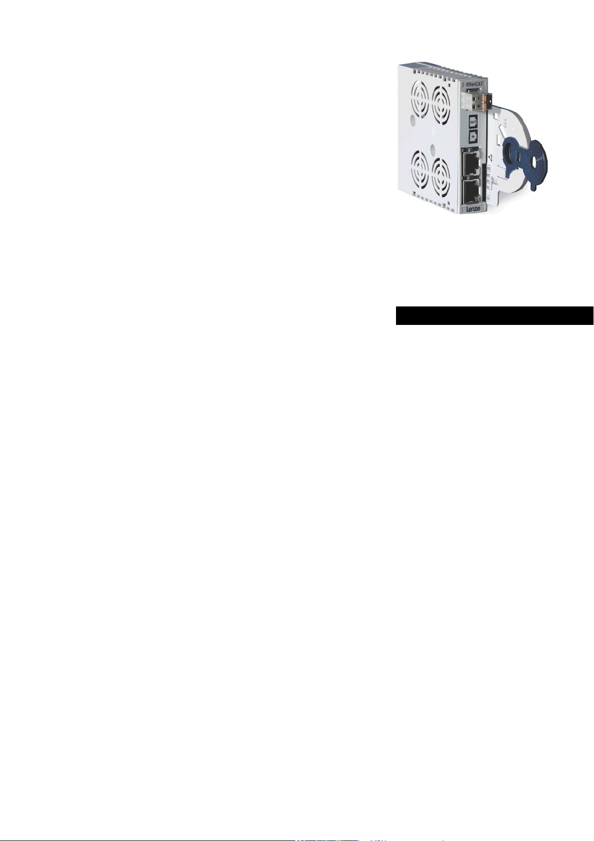
EtherCAT®
Servo Drives 9400
_ _ _ _ _ _ _ _ _ _ _ _ _ _ _ _ _ _ _ _ _ _ _ _ _ _
E94AYCET
Communication Manual EN
Ä.NZFä
13455737
L
Page 2

Contents
_ _ _ _ _ _ _ _ _ _ _ _ _ _ _ _ _ _ _ _ _ _ _ _ _ _ _ _ _ _ _ _ _ _ _ _ _ _ _ _ _ _ _ _ _ _ _ _ _ _ _ _ _ _ _ _ _ _ _ _ _ _ _ _
1 About this documentation _ _ _ _ _ _ _ _ _ _ _ _ _ _ _ _ _ _ _ _ _ _ _ _ _ _ _ _ _ _ _ _ _ _ _ _ _ _ _ 4
1.1 Document history _ _ _ _ _ _ _ _ _ _ _ _ _ _ _ _ _ _ _ _ _ _ _ _ _ _ _ _ _ _ _ _ _ _ _ _ _ _ _ _ _ _ _ _ 6
1.2 Conventions used _ _ _ _ _ _ _ _ _ _ _ _ _ _ _ _ _ _ _ _ _ _ _ _ _ _ _ _ _ _ _ _ _ _ _ _ _ _ _ _ _ _ _ _ 7
1.3 Terminology used _ _ _ _ _ _ _ _ _ _ _ _ _ _ _ _ _ _ _ _ _ _ _ _ _ _ _ _ _ _ _ _ _ _ _ _ _ _ _ _ _ _ _ _ 8
1.4 Definition of the notes used _ _ _ _ _ _ _ _ _ _ _ _ _ _ _ _ _ _ _ _ _ _ _ _ _ _ _ _ _ _ _ _ _ _ _ _ _ _ 9
2Safety instructions _ _ _ _ _ _ _ _ _ _ _ _ _ _ _ _ _ _ _ _ _ _ _ _ _ _ _ _ _ _ _ _ _ _ _ _ _ _ _ _ _ _ _ _ 10
2.1 General safety and application notes _ _ _ _ _ _ _ _ _ _ _ _ _ _ _ _ _ _ _ _ _ _ _ _ _ _ _ _ _ _ _ _ _ 10
2.2 Device- and application-specific safety instructions _ _ _ _ _ _ _ _ _ _ _ _ _ _ _ _ _ _ _ _ _ _ _ _ _ _ 11
2.3 Residual hazards _ _ _ _ _ _ _ _ _ _ _ _ _ _ _ _ _ _ _ _ _ _ _ _ _ _ _ _ _ _ _ _ _ _ _ _ _ _ _ _ _ _ _ _ _ 11
3 Product description _ _ _ _ _ _ _ _ _ _ _ _ _ _ _ _ _ _ _ _ _ _ _ _ _ _ _ _ _ _ _ _ _ _ _ _ _ _ _ _ _ _ _ 12
3.1 Application as directed _ _ _ _ _ _ _ _ _ _ _ _ _ _ _ _ _ _ _ _ _ _ _ _ _ _ _ _ _ _ _ _ _ _ _ _ _ _ _ _ _ 12
3.2 Identification _ _ _ _ _ _ _ _ _ _ _ _ _ _ _ _ _ _ _ _ _ _ _ _ _ _ _ _ _ _ _ _ _ _ _ _ _ _ _ _ _ _ _ _ _ _ _ 12
3.3 Product features _ _ _ _ _ _ _ _ _ _ _ _ _ _ _ _ _ _ _ _ _ _ _ _ _ _ _ _ _ _ _ _ _ _ _ _ _ _ _ _ _ _ _ _ _ 13
3.4 Terminals and interfaces _ _ _ _ _ _ _ _ _ _ _ _ _ _ _ _ _ _ _ _ _ _ _ _ _ _ _ _ _ _ _ _ _ _ _ _ _ _ _ _ 14
4 Technical data _ _ _ _ _ _ _ _ _ _ _ _ _ _ _ _ _ _ _ _ _ _ _ _ _ _ _ _ _ _ _ _ _ _ _ _ _ _ _ _ _ _ _ _ _ _ 15
4.1 General data and operating conditions _ _ _ _ _ _ _ _ _ _ _ _ _ _ _ _ _ _ _ _ _ _ _ _ _ _ _ _ _ _ _ _ 15
4.2 Protective insulation _ _ _ _ _ _ _ _ _ _ _ _ _ _ _ _ _ _ _ _ _ _ _ _ _ _ _ _ _ _ _ _ _ _ _ _ _ _ _ _ _ _ 16
4.3 Protocol data _ _ _ _ _ _ _ _ _ _ _ _ _ _ _ _ _ _ _ _ _ _ _ _ _ _ _ _ _ _ _ _ _ _ _ _ _ _ _ _ _ _ _ _ _ _ _ 19
4.4 Communication time _ _ _ _ _ _ _ _ _ _ _ _ _ _ _ _ _ _ _ _ _ _ _ _ _ _ _ _ _ _ _ _ _ _ _ _ _ _ _ _ _ _ 19
4.5 Dimensions _ _ _ _ _ _ _ _ _ _ _ _ _ _ _ _ _ _ _ _ _ _ _ _ _ _ _ _ _ _ _ _ _ _ _ _ _ _ _ _ _ _ _ _ _ _ _ 21
5Installation _ _ _ _ _ _ _ _ _ _ _ _ _ _ _ _ _ _ _ _ _ _ _ _ _ _ _ _ _ _ _ _ _ _ _ _ _ _ _ _ _ _ _ _ _ _ _ _ 22
5.1 Mechanical installation _ _ _ _ _ _ _ _ _ _ _ _ _ _ _ _ _ _ _ _ _ _ _ _ _ _ _ _ _ _ _ _ _ _ _ _ _ _ _ _ _ 23
5.1.1 Assembly _ _ _ _ _ _ _ _ _ _ _ _ _ _ _ _ _ _ _ _ _ _ _ _ _ _ _ _ _ _ _ _ _ _ _ _ _ _ _ _ _ _ _ _ 23
5.1.2 Disassembly _ _ _ _ _ _ _ _ _ _ _ _ _ _ _ _ _ _ _ _ _ _ _ _ _ _ _ _ _ _ _ _ _ _ _ _ _ _ _ _ _ _ 23
5.2 Electrical installation _ _ _ _ _ _ _ _ _ _ _ _ _ _ _ _ _ _ _ _ _ _ _ _ _ _ _ _ _ _ _ _ _ _ _ _ _ _ _ _ _ _ 24
5.2.1 EMC-compliant wiring _ _ _ _ _ _ _ _ _ _ _ _ _ _ _ _ _ _ _ _ _ _ _ _ _ _ _ _ _ _ _ _ _ _ _ _ _ 24
5.2.2 Network topology _ _ _ _ _ _ _ _ _ _ _ _ _ _ _ _ _ _ _ _ _ _ _ _ _ _ _ _ _ _ _ _ _ _ _ _ _ _ _ 25
5.2.3 EtherCAT connection _ _ _ _ _ _ _ _ _ _ _ _ _ _ _ _ _ _ _ _ _ _ _ _ _ _ _ _ _ _ _ _ _ _ _ _ _ _ 26
5.2.4 Specification of the Ethernet cable _ _ _ _ _ _ _ _ _ _ _ _ _ _ _ _ _ _ _ _ _ _ _ _ _ _ _ _ _ _ 27
5.2.5 External voltage supply _ _ _ _ _ _ _ _ _ _ _ _ _ _ _ _ _ _ _ _ _ _ _ _ _ _ _ _ _ _ _ _ _ _ _ _ 29
6 Commissioning _ _ _ _ _ _ _ _ _ _ _ _ _ _ _ _ _ _ _ _ _ _ _ _ _ _ _ _ _ _ _ _ _ _ _ _ _ _ _ _ _ _ _ _ _ 30
6.1 Before initial switch-on _ _ _ _ _ _ _ _ _ _ _ _ _ _ _ _ _ _ _ _ _ _ _ _ _ _ _ _ _ _ _ _ _ _ _ _ _ _ _ _ _ 30
6.2 Configuring the controller (EtherCAT master) _ _ _ _ _ _ _ _ _ _ _ _ _ _ _ _ _ _ _ _ _ _ _ _ _ _ _ _ _ 31
6.2.1 Installing device description files _ _ _ _ _ _ _ _ _ _ _ _ _ _ _ _ _ _ _ _ _ _ _ _ _ _ _ _ _ _ _ 31
6.2.2 Automatic device identification _ _ _ _ _ _ _ _ _ _ _ _ _ _ _ _ _ _ _ _ _ _ _ _ _ _ _ _ _ _ _ _ 32
6.2.3 Configuring process data _ _ _ _ _ _ _ _ _ _ _ _ _ _ _ _ _ _ _ _ _ _ _ _ _ _ _ _ _ _ _ _ _ _ _ 33
6.2.4 Determining the cycle time _ _ _ _ _ _ _ _ _ _ _ _ _ _ _ _ _ _ _ _ _ _ _ _ _ _ _ _ _ _ _ _ _ _ 33
6.3 Address allocation _ _ _ _ _ _ _ _ _ _ _ _ _ _ _ _ _ _ _ _ _ _ _ _ _ _ _ _ _ _ _ _ _ _ _ _ _ _ _ _ _ _ _ _ 34
6.4 Synchronisation with "Distributed Clocks" (DC) _ _ _ _ _ _ _ _ _ _ _ _ _ _ _ _ _ _ _ _ _ _ _ _ _ _ _ _ 35
6.4.1 DC configuration in the master _ _ _ _ _ _ _ _ _ _ _ _ _ _ _ _ _ _ _ _ _ _ _ _ _ _ _ _ _ _ _ _ 36
6.4.2 DC configuration in the Servo Drive 9400 (slave) _ _ _ _ _ _ _ _ _ _ _ _ _ _ _ _ _ _ _ _ _ _ 37
6.4.3 Response of the Lenze EtherCAT nodes during start-up _ _ _ _ _ _ _ _ _ _ _ _ _ _ _ _ _ _ _ 38
6.4.4 Process data mode _ _ _ _ _ _ _ _ _ _ _ _ _ _ _ _ _ _ _ _ _ _ _ _ _ _ _ _ _ _ _ _ _ _ _ _ _ _ _ 39
6.5 Establishing an online connection with the »Engineer« _ _ _ _ _ _ _ _ _ _ _ _ _ _ _ _ _ _ _ _ _ _ _ _ 40
6.5.1 Gateway controller -> configure EtherCAT _ _ _ _ _ _ _ _ _ _ _ _ _ _ _ _ _ _ _ _ _ _ _ _ _ _ 41
6.5.2 Gateway controller -> configure EtherCAT ADS (Beckhoff) _ _ _ _ _ _ _ _ _ _ _ _ _ _ _ _ _ 43
6.6 EtherCAT ADS communication parameters in »TwinCAT« and »Engineer« _ _ _ _ _ _ _ _ _ _ _ _ _ 45
6.6.1 Example: Structure without a Beckhoff controller _ _ _ _ _ _ _ _ _ _ _ _ _ _ _ _ _ _ _ _ _ _ 45
6.6.2 Example: Structure with a Beckhoff DIN rail IPC CX1020 _ _ _ _ _ _ _ _ _ _ _ _ _ _ _ _ _ _ 49
6.7 Initial switch-on _ _ _ _ _ _ _ _ _ _ _ _ _ _ _ _ _ _ _ _ _ _ _ _ _ _ _ _ _ _ _ _ _ _ _ _ _ _ _ _ _ _ _ _ _ 53
2 Lenze · E94AYCET communication module (EtherCAT®) · Communication Manual · DMS 9.0 EN · 02/2014 · TD17
Page 3

Contents
_ _ _ _ _ _ _ _ _ _ _ _ _ _ _ _ _ _ _ _ _ _ _ _ _ _ _ _ _ _ _ _ _ _ _ _ _ _ _ _ _ _ _ _ _ _ _ _ _ _ _ _ _ _ _ _ _ _ _ _ _ _ _ _
7 Data transfer _ _ _ _ _ _ _ _ _ _ _ _ _ _ _ _ _ _ _ _ _ _ _ _ _ _ _ _ _ _ _ _ _ _ _ _ _ _ _ _ _ _ _ _ _ _ _ 54
7.1 EtherCAT-Frames _ _ _ _ _ _ _ _ _ _ _ _ _ _ _ _ _ _ _ _ _ _ _ _ _ _ _ _ _ _ _ _ _ _ _ _ _ _ _ _ _ _ _ _ 55
7.2 EtherCAT datagrams _ _ _ _ _ _ _ _ _ _ _ _ _ _ _ _ _ _ _ _ _ _ _ _ _ _ _ _ _ _ _ _ _ _ _ _ _ _ _ _ _ _ _ 56
7.3 EtherCAT state machine _ _ _ _ _ _ _ _ _ _ _ _ _ _ _ _ _ _ _ _ _ _ _ _ _ _ _ _ _ _ _ _ _ _ _ _ _ _ _ _ _ 57
8 Process data transfer _ _ _ _ _ _ _ _ _ _ _ _ _ _ _ _ _ _ _ _ _ _ _ _ _ _ _ _ _ _ _ _ _ _ _ _ _ _ _ _ _ _ 59
8.1 Configuring process data (PDO mapping) _ _ _ _ _ _ _ _ _ _ _ _ _ _ _ _ _ _ _ _ _ _ _ _ _ _ _ _ _ _ _ 60
8.1.1 Setting PDO mapping with the »Engineer« _ _ _ _ _ _ _ _ _ _ _ _ _ _ _ _ _ _ _ _ _ _ _ _ _ 61
8.1.2 Mapping indices and codes _ _ _ _ _ _ _ _ _ _ _ _ _ _ _ _ _ _ _ _ _ _ _ _ _ _ _ _ _ _ _ _ _ _ 63
8.1.3 Structure of the mapping codes _ _ _ _ _ _ _ _ _ _ _ _ _ _ _ _ _ _ _ _ _ _ _ _ _ _ _ _ _ _ _ _ 64
8.2 Example of a drive initialisation with the "CiA402" technology application _ _ _ _ _ _ _ _ _ _ _ _ _ 65
9 Parameter data transfer _ _ _ _ _ _ _ _ _ _ _ _ _ _ _ _ _ _ _ _ _ _ _ _ _ _ _ _ _ _ _ _ _ _ _ _ _ _ _ _ _ 68
9.1 Establishing a connection between master and slave _ _ _ _ _ _ _ _ _ _ _ _ _ _ _ _ _ _ _ _ _ _ _ _ _ 68
9.2 Reading and writing parameters _ _ _ _ _ _ _ _ _ _ _ _ _ _ _ _ _ _ _ _ _ _ _ _ _ _ _ _ _ _ _ _ _ _ _ _ 69
9.2.1 Reading parameters (SDO upload) _ _ _ _ _ _ _ _ _ _ _ _ _ _ _ _ _ _ _ _ _ _ _ _ _ _ _ _ _ _ 70
9.2.2 Writing parameters (SDO download) _ _ _ _ _ _ _ _ _ _ _ _ _ _ _ _ _ _ _ _ _ _ _ _ _ _ _ _ _ 74
9.3 Implemented CoE objects _ _ _ _ _ _ _ _ _ _ _ _ _ _ _ _ _ _ _ _ _ _ _ _ _ _ _ _ _ _ _ _ _ _ _ _ _ _ _ _ 79
9.4 SDO abort codes (Abort codes) _ _ _ _ _ _ _ _ _ _ _ _ _ _ _ _ _ _ _ _ _ _ _ _ _ _ _ _ _ _ _ _ _ _ _ _ _ 80
10 Monitoring _ _ _ _ _ _ _ _ _ _ _ _ _ _ _ _ _ _ _ _ _ _ _ _ _ _ _ _ _ _ _ _ _ _ _ _ _ _ _ _ _ _ _ _ _ _ _ _ 81
10.1 Interruption of EtherCAT communication _ _ _ _ _ _ _ _ _ _ _ _ _ _ _ _ _ _ _ _ _ _ _ _ _ _ _ _ _ _ _ 81
10.2 Interruption of internal communication _ _ _ _ _ _ _ _ _ _ _ _ _ _ _ _ _ _ _ _ _ _ _ _ _ _ _ _ _ _ _ _ 82
10.3 Frame failure detection through the application _ _ _ _ _ _ _ _ _ _ _ _ _ _ _ _ _ _ _ _ _ _ _ _ _ _ _ 82
10.4 EtherCAT synchronisation loss _ _ _ _ _ _ _ _ _ _ _ _ _ _ _ _ _ _ _ _ _ _ _ _ _ _ _ _ _ _ _ _ _ _ _ _ _ 82
11 Diagnostics _ _ _ _ _ _ _ _ _ _ _ _ _ _ _ _ _ _ _ _ _ _ _ _ _ _ _ _ _ _ _ _ _ _ _ _ _ _ _ _ _ _ _ _ _ _ _ _ 83
11.1 LED status displays _ _ _ _ _ _ _ _ _ _ _ _ _ _ _ _ _ _ _ _ _ _ _ _ _ _ _ _ _ _ _ _ _ _ _ _ _ _ _ _ _ _ _ 83
11.1.1 Module status displays _ _ _ _ _ _ _ _ _ _ _ _ _ _ _ _ _ _ _ _ _ _ _ _ _ _ _ _ _ _ _ _ _ _ _ _ 84
11.1.2 EtherCAT status displays _ _ _ _ _ _ _ _ _ _ _ _ _ _ _ _ _ _ _ _ _ _ _ _ _ _ _ _ _ _ _ _ _ _ _ 85
11.1.3 Status display at the RJ45 sockets (X246 / X247) _ _ _ _ _ _ _ _ _ _ _ _ _ _ _ _ _ _ _ _ _ _ 87
11.2 Diagnostics with the »Engineer« _ _ _ _ _ _ _ _ _ _ _ _ _ _ _ _ _ _ _ _ _ _ _ _ _ _ _ _ _ _ _ _ _ _ _ _ 88
11.3 Emergency requests / Emergency messages _ _ _ _ _ _ _ _ _ _ _ _ _ _ _ _ _ _ _ _ _ _ _ _ _ _ _ _ _ _ 89
12 Error messages _ _ _ _ _ _ _ _ _ _ _ _ _ _ _ _ _ _ _ _ _ _ _ _ _ _ _ _ _ _ _ _ _ _ _ _ _ _ _ _ _ _ _ _ _ _ 90
12.1 Short overview of the EtherCAT error messages _ _ _ _ _ _ _ _ _ _ _ _ _ _ _ _ _ _ _ _ _ _ _ _ _ _ _ _ 90
12.2 Possible causes and remedies _ _ _ _ _ _ _ _ _ _ _ _ _ _ _ _ _ _ _ _ _ _ _ _ _ _ _ _ _ _ _ _ _ _ _ _ _ _ 91
13 Parameter reference _ _ _ _ _ _ _ _ _ _ _ _ _ _ _ _ _ _ _ _ _ _ _ _ _ _ _ _ _ _ _ _ _ _ _ _ _ _ _ _ _ _ _ 94
13.1 Communication-relevant parameters of the standard device _ _ _ _ _ _ _ _ _ _ _ _ _ _ _ _ _ _ _ _ 94
13.2 Parameters of the communication module for slot MXI1 _ _ _ _ _ _ _ _ _ _ _ _ _ _ _ _ _ _ _ _ _ _ _ 97
13.3 Parameters of the communication module for slot MXI2 _ _ _ _ _ _ _ _ _ _ _ _ _ _ _ _ _ _ _ _ _ _ _ 114
13.4 Table of attributes _ _ _ _ _ _ _ _ _ _ _ _ _ _ _ _ _ _ _ _ _ _ _ _ _ _ _ _ _ _ _ _ _ _ _ _ _ _ _ _ _ _ _ _ 131
Index _ _ _ _ _ _ _ _ _ _ _ _ _ _ _ _ _ _ _ _ _ _ _ _ _ _ _ _ _ _ _ _ _ _ _ _ _ _ _ _ _ _ _ _ _ _ _ _ _ _ _ 134
Your opinion is important to us _ _ _ _ _ _ _ _ _ _ _ _ _ _ _ _ _ _ _ _ _ _ _ _ _ _ _ _ _ _ _ _ _ _ _ _ _ 139
Lenze · E94AYCET communication module (EtherCAT®) · Communication Manual · DMS 9.0 EN · 02/2014 · TD17 3
Page 4

1 About this documentation
_ _ _ _ _ _ _ _ _ _ _ _ _ _ _ _ _ _ _ _ _ _ _ _ _ _ _ _ _ _ _ _ _ _ _ _ _ _ _ _ _ _ _ _ _ _ _ _ _ _ _ _ _ _ _ _ _ _ _ _ _ _ _ _
1 About this documentation
Contents
This documentation only contains descriptions for the E94AYCET communication module
(EtherCAT®).
Note!
This documentation supplements the Mounting Instructions supplied with the
communication module and the Servo Drives 9400 hardware manual.
The Mounting Instructions contain safety instructions which must be observed!
The features and functions of the communication module are described in detail.
Examples illustrate typical applications.
The theoretical concepts are only explained to the level of detail required to understand the
function of the communication module.
This documentation does not describe any software provided by other manufacturers. No warranty
can be given for corresponding data provided in this documentation. For information on how to use
the software, please refer to the control system documents (controller, EtherCAT master).
All product names mentioned in this documentation are trademarks of their corresponding owners.
Tip!
Detailed information about EtherCAT can be found on the website of the EtherCAT
Technology Group:
www.ethercat.org
4 Lenze · E94AYCET communication module (EtherCAT®) · Communication Manual · DMS 9.0 EN · 02/2014 · TD17
Page 5

1 About this documentation
_ _ _ _ _ _ _ _ _ _ _ _ _ _ _ _ _ _ _ _ _ _ _ _ _ _ _ _ _ _ _ _ _ _ _ _ _ _ _ _ _ _ _ _ _ _ _ _ _ _ _ _ _ _ _ _ _ _ _ _ _ _ _ _
Target group
This documentation is intended for all persons who plan, install, commission and maintain the
networking and remote servicing of a machine.
Tip!
Current documentation and software updates with regard to Lenze products can be found
in the download area at:
www.lenze.com
Validity information
The information in this documentation applies to the following devices:
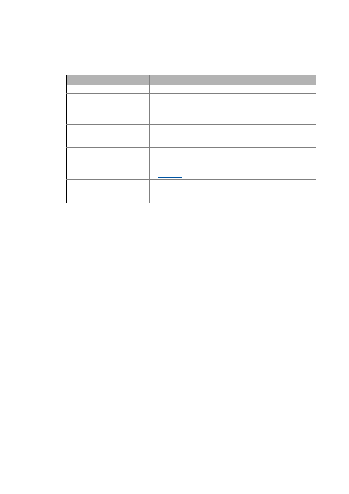
Extension module Type designation From hardware
version
EtherCAT communication module E94AYCET VE 03.00
Screenshots/application examples
All screenshots in this documentation are application examples. Depending on the firmware
version of the communication module and the software version of the engineering tools installed
(e.g. »Engineer«, »TwinCAT«), the screenshots in this documentation may differ from the actual
screen representation.
From software
version
Lenze · E94AYCET communication module (EtherCAT®) · Communication Manual · DMS 9.0 EN · 02/2014 · TD17 5
Page 6
1 About this documentation
1.1 Document history
_ _ _ _ _ _ _ _ _ _ _ _ _ _ _ _ _ _ _ _ _ _ _ _ _ _ _ _ _ _ _ _ _ _ _ _ _ _ _ _ _ _ _ _ _ _ _ _ _ _ _ _ _ _ _ _ _ _ _ _ _ _ _ _
1.1 Document history
Version Description
1.0 04/2008 TD17 First edition
2.0 07/2009 TD17 General revision
3.0 11/2009 TD17 Amendment of the information on the fieldbus synchronisation and general
4.0 04/2010 TD17 General revision
5.0 11/2010 TD17 • General revision
6.0 03/2011 TD17 General revision
7.0 07/2012 TD17 • General revision
8.0 01/2013 TD17 • Update for C13861
9.0 02/2014 TD17 General updates
revision
• Update for SW version 03.00
• Information about the EtherCAT register "AL Status Code
supplemented.
•Chapter EtherCAT ADS communication parameters in »TwinCAT« and
»Engineer« ( 45) supplemented.
/ C14861 (bus status)
•New layout
" ( 58)
6
Lenze · E94AYCET communication module (EtherCAT®) · Communication Manual · DMS 9.0 EN · 02/2014 · TD17
Page 7

1 About this documentation
1.2 Conventions used
_ _ _ _ _ _ _ _ _ _ _ _ _ _ _ _ _ _ _ _ _ _ _ _ _ _ _ _ _ _ _ _ _ _ _ _ _ _ _ _ _ _ _ _ _ _ _ _ _ _ _ _ _ _ _ _ _ _ _ _ _ _ _ _
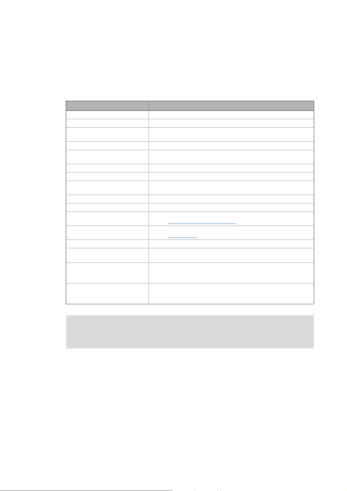
1.2 Conventions used
This documentation uses the following conventions to distinguish different types of information:
Type of information Identification Examples/notes
Numbers
Decimal Standard notation Example: 1234
Decimal separator Point In general, the decimal point is used.
Example: 1234.56
Hexadecimal 0x[0 ... 9, A ... F] Example: 0x60F4
Binary
• Nibble
Text
Version information Text colour blue All pieces of information that only apply to or from a specific
Program name » « The Lenze PC software »Engineer«...
Control element Bold The OK button... / The Copy command... / The Properties
Sequence of menu
commands
Hyperlink Underlined
Icons
Page reference ( 9) Optically highlighted reference to another page. Can be
Step-by-step instructions
In inverted commas
Point
Example: ’100’
Example: ’0110.0100’
software version of the device are highlighted accordingly in
this documentation.
Example: This function extension is available from software
version V3.0!
tab... / The Name input field...
If several successive commands are required for executing a
function, the individual commands are separated from each
other by an arrow: Select the command File
Optically highlighted reference to another topic. Can be
activated with a mouse-click in this online documentation.
activated with a mouse-click in this online documentation.
Step-by-step instructions are marked by a pictograph.
Open to...
Lenze · E94AYCET communication module (EtherCAT®) · Communication Manual · DMS 9.0 EN · 02/2014 · TD17 7
Page 8

1 About this documentation
1.3 Terminology used
_ _ _ _ _ _ _ _ _ _ _ _ _ _ _ _ _ _ _ _ _ _ _ _ _ _ _ _ _ _ _ _ _ _ _ _ _ _ _ _ _ _ _ _ _ _ _ _ _ _ _ _ _ _ _ _ _ _ _ _ _ _ _ _
1.3 Terminology used
Term Meaning
Drive Lenze inverter of the "Servo Drives 9400" product range
Standard device
Code Parameter which serves to parameterise and monitor the drive. In normal usage,
Subcode If a code contains several parameters, they are stored in so-called "subcodes".
CoE CANopen over EtherCAT
Controller EtherCAT master
Control system
DC "Distributed clocks" for EtherCAT synchronisation
»Engineer« PC software from Lenze which supports you during engineering
»PLC Designer«
ESI "EtherCAT slave information"
"Hot connect" This feature makes it possible to remove and connect slave field devices during
HW Hardware
I-1600.8 CoE index (hexadecimal representation)
Lenze setting Settings with which the device is preconfigured ex works.
Standard setting
PDO Process data object
SDO Service data object
SW Software
»TwinCAT« Beckhoff PC software for EtherCAT configuration
the term is usually referred to as "Index".
This manual uses a slash "/" as a separator between code and subcode
(e.g. "C00118/3").
In normal usage, the term is also referred to as "Subindex".
(parameterisation, diagnostics, and configuration) throughout the entire life
cycle, i.e. from planning to maintenance of the commissioned machine.
(device description file in XML format)
EtherCAT® (Ethernet for Controller and Automation Technology) is an Ethernetbased fieldbus system which meets the application profile for industrial realtime systems.
EtherCAT® is a registered trademark and patented technology, licenced by
Beckhoff Automation GmbH, Germany.
operation.
In the example: index 0x1600, subindex 8
8
Lenze · E94AYCET communication module (EtherCAT®) · Communication Manual · DMS 9.0 EN · 02/2014 · TD17
Page 9

1 About this documentation
1.4 Definition of the notes used
_ _ _ _ _ _ _ _ _ _ _ _ _ _ _ _ _ _ _ _ _ _ _ _ _ _ _ _ _ _ _ _ _ _ _ _ _ _ _ _ _ _ _ _ _ _ _ _ _ _ _ _ _ _ _ _ _ _ _ _ _ _ _ _
1.4 Definition of the notes used
The following signal words and symbols are used in this documentation to indicate dangers and
important information:
Safety instructions
Layout of the safety instructions:
Danger!
(characterises the type and severity of danger)
Note
(describes the danger and suggests how to prevent dangerous situations)
Pictograph Signal word Meaning
Danger! Danger of personal injury through dangerous electrical voltage
Danger! Danger of personal injury through a general source of danger
Stop! Danger of damage to material assets
Application notes
Reference to an imminent danger that may result in death or serious personal
injury if the corresponding measures are not taken.
Reference to an imminent danger that may result in death or serious personal
injury if the corresponding measures are not taken.
Reference to a possible danger that may result in damage to material assets if
the corresponding measures are not taken.
Pictograph Signal word Meaning
Note! Important note to ensure trouble-free operation
Tip! Useful tip for easy handling
Reference to other documentation
Lenze · E94AYCET communication module (EtherCAT®) · Communication Manual · DMS 9.0 EN · 02/2014 · TD17 9
Page 10

2 Safety instructions
2.1 General safety and application notes
_ _ _ _ _ _ _ _ _ _ _ _ _ _ _ _ _ _ _ _ _ _ _ _ _ _ _ _ _ _ _ _ _ _ _ _ _ _ _ _ _ _ _ _ _ _ _ _ _ _ _ _ _ _ _ _ _ _ _ _ _ _ _ _
2 Safety instructions
Note!
Always observe the specified safety measures to avoid severe injury to persons and
damage to property!
Always keep this documentation to hand in the vicinity of the product during operation.
2.1 General safety and application notes
Danger!
If you ignore the following basic safety measures, severe injury to persons and damage
to material assets may result.
Lenze drive and automation components ...
• must only be used as directed.
Application as directed
• must never be commissioned if they display any signs of damage.
• must never be technically modified.
• must never be commissioned if they are not fully mounted.
• must never be operated without the covers required.
• during and after operation can have live, moving and rotating parts, depending on their degree
of protection. Surfaces can be hot.
For Lenze drive components ...
• only use the accessories approved.
• only use genuine spare parts supplied by the manufacturer of the product.
Observe all specifications contained in the enclosed documentation and related documentation.
• This is the precondition for safe and trouble-free operation and for obtaining the product
features specified.
Product features
• The specifications, processes, and circuitry described in this document are for guidance only and
must be adapted to your own specific application. Lenze does not take responsibility for the
suitability of the process and circuit proposals.
( 12)
( 13)
10
Only qualified personnel may work with and on Lenze drive and automation components.
According to IEC 60364 and CENELEC HD 384, these are persons ...
• who are familiar with the installation, assembly, commissioning and operation of the product.
• who have the corresponding qualifications for their work.
• who know all regulations for the prevention of accidents, directives and laws applicable on site
and are able to apply them.
Lenze · E94AYCET communication module (EtherCAT®) · Communication Manual · DMS 9.0 EN · 02/2014 · TD17
Page 11

2 Safety instructions
2.2 Device- and application-specific safety instructions
_ _ _ _ _ _ _ _ _ _ _ _ _ _ _ _ _ _ _ _ _ _ _ _ _ _ _ _ _ _ _ _ _ _ _ _ _ _ _ _ _ _ _ _ _ _ _ _ _ _ _ _ _ _ _ _ _ _ _ _ _ _ _ _
2.2 Device- and application-specific safety instructions
• During operation, the communication module must be firmly connected to the standard device.
• With external voltage supply, always use a separate power supply unit, safely separated to
EN 61800-5-1 in every control cabinet (SELV/PELV).
External voltage supply
• Only use cables that correspond to the given specifications.
Specification of the Ethernet cable
( 29)
( 27)
Documentation for the standard device, control system, plant/machine
All the other measures prescribed in this documentation must also be implemented.
Observe the safety instructions and application notes stated in this manual.
2.3 Residual hazards
Protection of persons
If Servo Drives 9400 are used on a phase earthed mains with a rated mains voltage of 400V,
protection against accidental contact is not ensured without external measures.
Protective insulation
Device protection
The communication module contains electronic components that can be damaged or destroyed by
electrostatic discharge.
Installation
( 22)
( 16)
Lenze · E94AYCET communication module (EtherCAT®) · Communication Manual · DMS 9.0 EN · 02/2014 · TD17 11
Page 12
3 Product description
3.1 Application as directed
_ _ _ _ _ _ _ _ _ _ _ _ _ _ _ _ _ _ _ _ _ _ _ _ _ _ _ _ _ _ _ _ _ _ _ _ _ _ _ _ _ _ _ _ _ _ _ _ _ _ _ _ _ _ _ _ _ _ _ _ _ _ _ _
3 Product description
3.1 Application as directed
The communication module ...
• is an accessory module which can be used with the following standard devices:
Product series Type designation From hardware
Servo Drives 9400 HighLine E94AxHxxxx VA 01.51
Servo Drives 9400 PLC E94AxPExxxx VA 02.00
Regenerative power supply module E94ARNxxxx VA 01.00
• is an item of equipment intended for use in industrial power systems.
• may only be operated under the operating conditions specified in this documentation.
• may only be used in EtherCAT networks.
Any other use shall be deemed inappropriate!
3.2 Identification
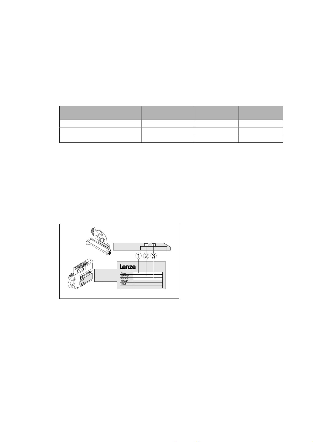
The type designation and the hardware and software version of the communication module are
specified on the nameplate:
[3-1] Identification data
E94YCET005
version
1 Type designation (type)
E94 Product series
AVersion
Y Module identification: Extension module
C Module type: Communication module
ET EtherCAT
2 Hardware version (HW)
3 Software version (SW)
From software
version
12
Lenze · E94AYCET communication module (EtherCAT®) · Communication Manual · DMS 9.0 EN · 02/2014 · TD17
Page 13

3 Product description
3.3 Product features
_ _ _ _ _ _ _ _ _ _ _ _ _ _ _ _ _ _ _ _ _ _ _ _ _ _ _ _ _ _ _ _ _ _ _ _ _ _ _ _ _ _ _ _ _ _ _ _ _ _ _ _ _ _ _ _ _ _ _ _ _ _ _ _
3.3 Product features
• Interface module for the EtherCAT communication system to be connected to the expansion
slots of the Servo Drives 9400
• The communication module can be supplied internally by the standard device and externally via
a separate voltage source.
• The CANopen device profile CiA402 in connection with Servo Drives 9400 HighLine is available
from software version 7.0.
• Supports the "Distributed Clocks" (DC) functionality for synchronisation via the fieldbus
•Cycle times:
• 1 ms or an integer multiple of 1 ms
• max. 15 ms if "Distributed Clocks" (DC) are used
• Up to 32 process data words (16 bits/word) per direction can be exchanged.
• PDO transfer with CoE (CANopen over EtherCAT)
• Access to all Lenze parameters with CoE (CANopen over EtherCAT)
Lenze · E94AYCET communication module (EtherCAT®) · Communication Manual · DMS 9.0 EN · 02/2014 · TD17 13
Page 14
3 Product description
3.4 Terminals and interfaces
_ _ _ _ _ _ _ _ _ _ _ _ _ _ _ _ _ _ _ _ _ _ _ _ _ _ _ _ _ _ _ _ _ _ _ _ _ _ _ _ _ _ _ _ _ _ _ _ _ _ _ _ _ _ _ _ _ _ _ _ _ _ _ _
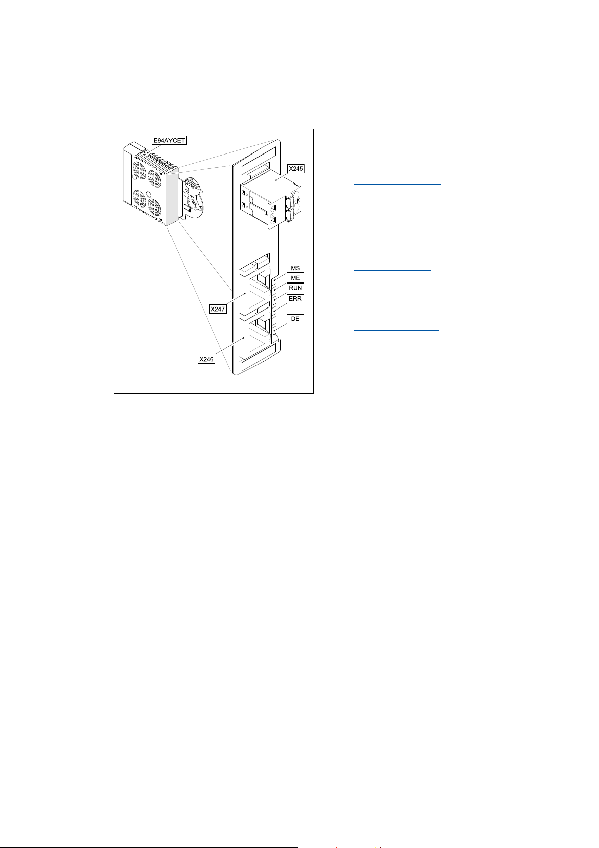
3.4 Terminals and interfaces
X245 External voltage supply of the communication
module
2-pole plug connector with spring connection
External voltage supply
X246 EtherCAT input (IN)
X247 EtherCAT output (OUT)
• RJ45 sockets
• with 2 LED status displays each for diagnostics
Network topology
EtherCAT connection
Status display at the RJ45 sockets (X246 / X247)
( 87)
5 LED status displays for diagnostics
MS
Module status displays
ME
RUN
EtherCAT status displays
ERR
DE
( 29)
( 25)
( 26)
( 84)
( 85)
E94YCET001B
[3-2] E94AYCET communication module (EtherCAT)
14
Lenze · E94AYCET communication module (EtherCAT®) · Communication Manual · DMS 9.0 EN · 02/2014 · TD17
Page 15
4Technical data
4.1 General data and operating conditions
_ _ _ _ _ _ _ _ _ _ _ _ _ _ _ _ _ _ _ _ _ _ _ _ _ _ _ _ _ _ _ _ _ _ _ _ _ _ _ _ _ _ _ _ _ _ _ _ _ _ _ _ _ _ _ _ _ _ _ _ _ _ _ _
4 Technical data
4.1 General data and operating conditions
Area Values
Order designation E94AYCET
Communication profile EtherCAT
Supported device profile and mailbox
protocol
Communication medium S/FTP (Screened Foiled Twisted Pair, ISO/IEC 11801 or EN 50173), CAT 5e
Interface for communication RJ45: Standard Ethernet (in accordance with IEEE 802.3), 100Base-TX (Fast
Network topology Line, switch
Number of nodes Max. 65535 ( in the entire network )
Max. cable length between two
EtherCAT nodes
Bus device type EtherCAT slave
Vendor ID [hex] 0x3B
Product ID Depending on the basic device and the selected technology application (see
Revision ID Depending on the main software version of the communication module (see
Baud rate 100 Mbps, full duplex
Cycle times 1 ms or an integer multiple of 1 ms,
Voltage supply External supply via a separate power supply unit
Conformity, approvals • CE
CANopen over EtherCAT (CoE)
Ethernet)
100 m (typically)
chapter Automatic device identification
chapter Identification
max. 15 ms if "Distributed clocks" (DC) are used
+: U = 24 V DC (20.4 V - 0 % ... 28.8 V + 0 %), I = 130 mA
-: reference potential for external voltage supply
•UL
(see also hardware manual)
( 12)).
( 32)).
Servo Drives 9400 hardware manual
Here you can find the ambient conditions and information on the electromagnetic
compatibility (EMC) which also apply to the communication module.
Lenze · E94AYCET communication module (EtherCAT®) · Communication Manual · DMS 9.0 EN · 02/2014 · TD17 15
Page 16

4Technical data
4.2 Protective insulation
_ _ _ _ _ _ _ _ _ _ _ _ _ _ _ _ _ _ _ _ _ _ _ _ _ _ _ _ _ _ _ _ _ _ _ _ _ _ _ _ _ _ _ _ _ _ _ _ _ _ _ _ _ _ _ _ _ _ _ _ _ _ _ _
4.2 Protective insulation
Danger!
Dangerous voltage
If the Servo Drives 9400 are operated on a phase earthed mains with a rated mains
voltage 400 V, external measures need to be implemented in order to ensure
protection against accidental contact.
Possible consequences:
Death or severe injury
Protective measures:
If protection against accidental contact is required for the control terminals of the drive
and the connections of the plugged device modules, ...
• a double isolating distance must be available.
• the components to be connected must be provided with a second isolating distance.
Note!
The existing protective insulation in the Servo Drives 9400 is implemented according to
EN 61800-5-1.
16
Lenze · E94AYCET communication module (EtherCAT®) · Communication Manual · DMS 9.0 EN · 02/2014 · TD17
Page 17
4Technical data
Ext. DC
I/O
X4
X6X6
X5
X7X7
X8X8
X3
X2
X1
X105X105
X106
X100
X107
MXI1
MXI2
Bus
Ext. DC
MSI
MMI
4.2 Protective insulation
_ _ _ _ _ _ _ _ _ _ _ _ _ _ _ _ _ _ _ _ _ _ _ _ _ _ _ _ _ _ _ _ _ _ _ _ _ _ _ _ _ _ _ _ _ _ _ _ _ _ _ _ _ _ _ _ _ _ _ _ _ _ _ _
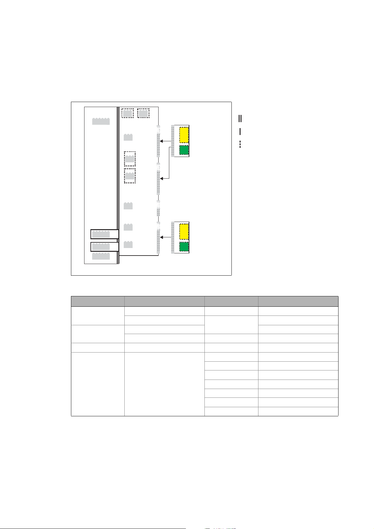
The following illustration ...
• shows the arrangement of the terminal strips and the separate potential areas of the drive.
• serves to determine the decisive protective insulation between two terminals located in
differently insulated separate potential areas.
Reinforced insulation
Basic insulation
Functional insulation
[4-1] Protective insulation in accordance with EN61800-5-1
Terminal strip Connection Terminal strip Connection
X100 L1, L2, L3 (Single Drive only) X1 CAN on board 9400
+UG, -UG X2 State bus
X105 U, V, W 24 V (ext.)
Rb1, Rb2 (Single Drive only) X3 Analog inputs/outputs
X106 Motor PTC X4 Digital outputs
X107 Control of the motor holding
brake
E94YCXX007
X5 Digital inputs
X6 Diagnostics
X7 Resolver
X8 Encoder
MXI1, MXI2 Extension module
MMI Memory module
MSI Safety module
Lenze · E94AYCET communication module (EtherCAT®) · Communication Manual · DMS 9.0 EN · 02/2014 · TD17 17
Page 18

4Technical data
4.2 Protective insulation
_ _ _ _ _ _ _ _ _ _ _ _ _ _ _ _ _ _ _ _ _ _ _ _ _ _ _ _ _ _ _ _ _ _ _ _ _ _ _ _ _ _ _ _ _ _ _ _ _ _ _ _ _ _ _ _ _ _ _ _ _ _ _ _
Example
Which type of protective insulation is used between the bus terminal of the device module in slot
MXI1 or MXI2 and the mains terminal X100?
The separate potential area with the better protective insulation is decisive.
• The separate potential area of the bus terminal of the device module has a "basic insulation".
• The separate potential area of the mains terminal has a "reinforced insulation".
Result: The insulation between the X100 mains terminal and the bus terminal is of the "reinforced
insulation" type.
18
Lenze · E94AYCET communication module (EtherCAT®) · Communication Manual · DMS 9.0 EN · 02/2014 · TD17
Page 19

4Technical data
4.3 Protocol data
_ _ _ _ _ _ _ _ _ _ _ _ _ _ _ _ _ _ _ _ _ _ _ _ _ _ _ _ _ _ _ _ _ _ _ _ _ _ _ _ _ _ _ _ _ _ _ _ _ _ _ _ _ _ _ _ _ _ _ _ _ _ _ _
4.3 Protocol data
Area Values
Process data 1 ... 32 process data words for each direction
(max. 64 bytes, 16 bits / word)
Parameter data (mailbox size for CoE
transfer)
4.4 Communication time
Parameter data (SDO)
The communication time for parameter data is the time between the transmission of an SDO
request and the arrival of the corresponding response.
The processing time in the drive is approx. 30ms+20ms tolerance (typical)
Some codes may require a longer processing time (see reference manual/»Engineer« online help for
Servo Drive 9400).
Max. 128 bytes
Process data (PDO)
The communication time for process data is the time between the reception of a PDO with setpoints
and the return of a PDO with the current actual values.
The communication times for process data depend on the ...
• processing time in the drive (interval time of the application task, process data mode);
• Runtime on the fieldbus (frame length, number of nodes, PDO update time, instant of
transmission of the EtherCAT frame);
• Use of the "Distributed clocks" (DC) functionality for synchronised operation.
Synchronisation with "Distributed Clocks" (DC)
( 35)
Lenze · E94AYCET communication module (EtherCAT®) · Communication Manual · DMS 9.0 EN · 02/2014 · TD17 19
Page 20

4Technical data
4.4 Communication time
_ _ _ _ _ _ _ _ _ _ _ _ _ _ _ _ _ _ _ _ _ _ _ _ _ _ _ _ _ _ _ _ _ _ _ _ _ _ _ _ _ _ _ _ _ _ _ _ _ _ _ _ _ _ _ _ _ _ _ _ _ _ _ _
The mentioned basic conditions result in the following processing times for the process data in the
drive:
• DC use (synchronised operation):
The processing time starts with the acceptance of the setpoints by the drive with the Sync0
event (DC synchronisation cycle) and ends with the provision of the current actual values in the
EtherCAT interface.
Depending on the selected Process data mode
processing times result:
• Deterministic mode: 2.1 ms + interval time of the application task
• Optimised mode: 1.3 ms + interval time of the application task
• No DC use (non-synchronised operation):
The processing time starts with the acceptance of the setpoints by the drive at a time that is not
synchronised with the EtherCAT master and ends with the provision of the current actual values
in the EtherCAT interface.
The following processing time arises:
1.3 ms + 1.0 ms (tolerance) + interval time of the application task
( 39) (C13892 / C14892), the following
Documentation of the 9400 function library
Here you can find detailed information on how to set the interval time of the application
task.
20
Lenze · E94AYCET communication module (EtherCAT®) · Communication Manual · DMS 9.0 EN · 02/2014 · TD17
Page 21
4Technical data
4.5 Dimensions
_ _ _ _ _ _ _ _ _ _ _ _ _ _ _ _ _ _ _ _ _ _ _ _ _ _ _ _ _ _ _ _ _ _ _ _ _ _ _ _ _ _ _ _ _ _ _ _ _ _ _ _ _ _ _ _ _ _ _ _ _ _ _ _
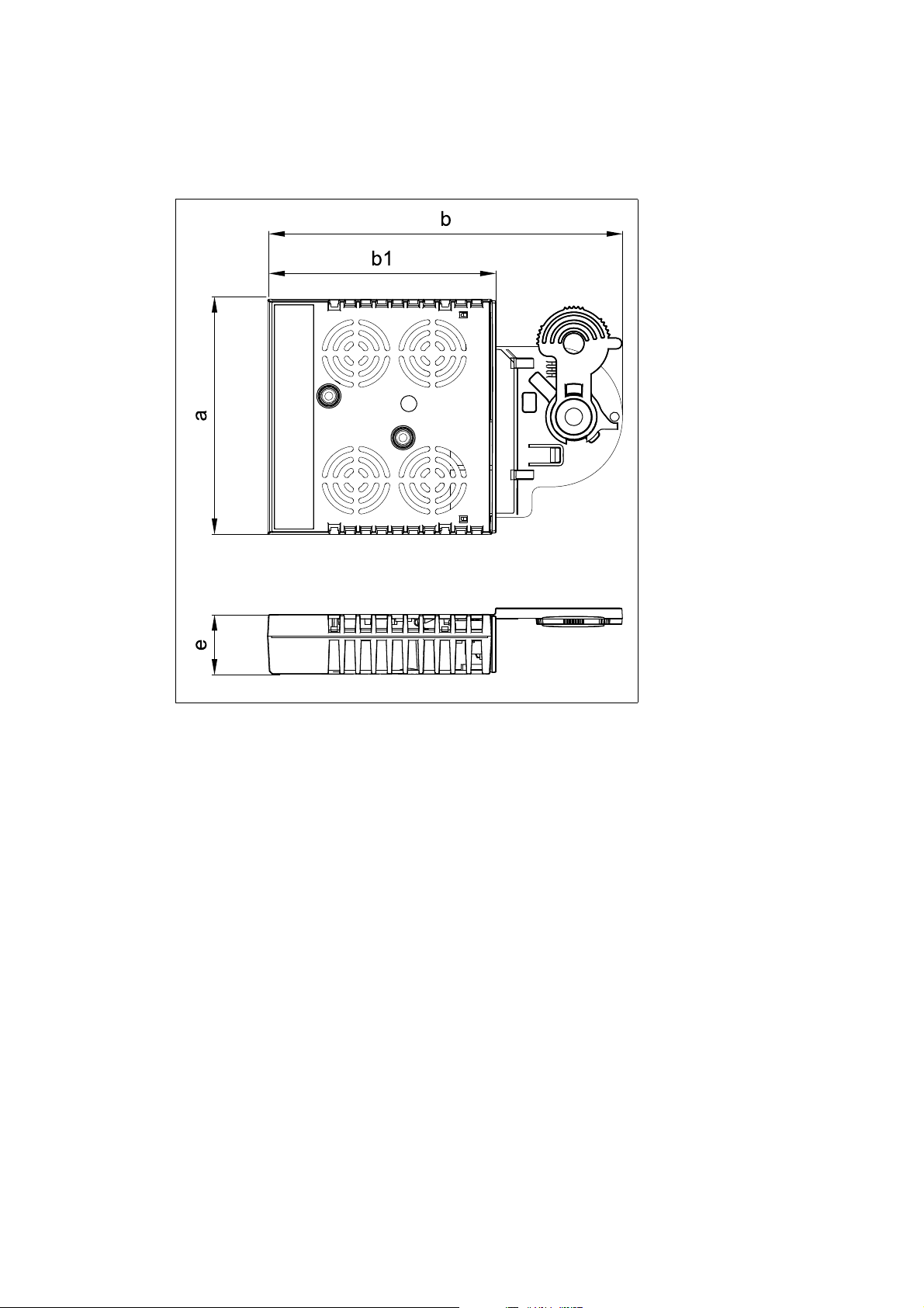
4.5 Dimensions
a 89 mm
b 134 mm
b1 87 mm
e 23 mm
[4-2] Dimensions
E94YCXX005
Lenze · E94AYCET communication module (EtherCAT®) · Communication Manual · DMS 9.0 EN · 02/2014 · TD17 21
Page 22

5 Installation
_ _ _ _ _ _ _ _ _ _ _ _ _ _ _ _ _ _ _ _ _ _ _ _ _ _ _ _ _ _ _ _ _ _ _ _ _ _ _ _ _ _ _ _ _ _ _ _ _ _ _ _ _ _ _ _ _ _ _ _ _ _ _ _
5 Installation
Stop!
Electrostatic discharge
Electronic components in the communication module can be damaged or destroyed by
electrostatic discharge.
Possible consequences:
• The communication module is defective.
• Fieldbus communication is faulty or not possible.
Protective measures:
Before touching the module, make sure that you are free of electrostatic charge.
22 Lenze · E94AYCET communication module (EtherCAT®) · Communication Manual · DMS 9.0 EN · 02/2014 · TD17
Page 23
5 Installation
5.1 Mechanical installation
_ _ _ _ _ _ _ _ _ _ _ _ _ _ _ _ _ _ _ _ _ _ _ _ _ _ _ _ _ _ _ _ _ _ _ _ _ _ _ _ _ _ _ _ _ _ _ _ _ _ _ _ _ _ _ _ _ _ _ _ _ _ _ _
5.1 Mechanical installation
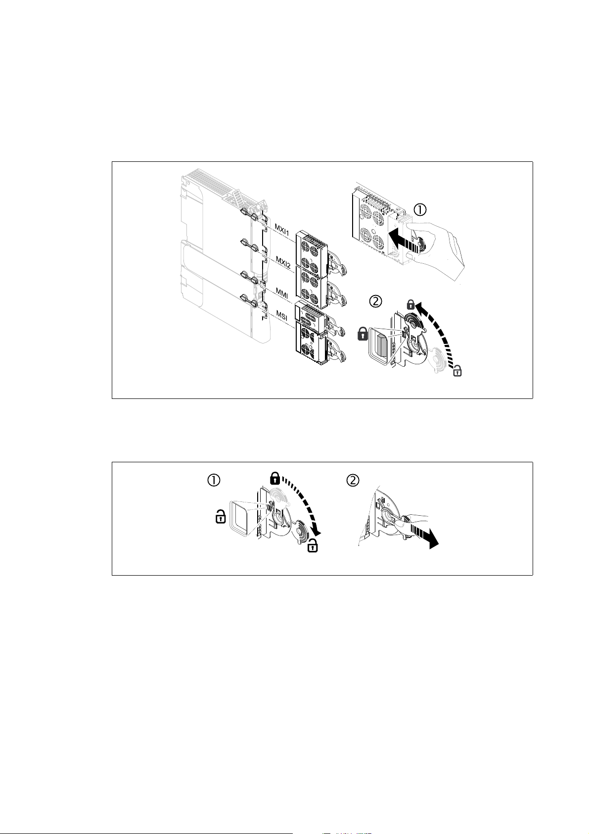
5.1.1 Assembly
[5-1] Assembly
5.1.2 Disassembly
[5-2] Disassembly
E94YCXX001G
E94AYCXX001H
Lenze · E94AYCET communication module (EtherCAT®) · Communication Manual · DMS 9.0 EN · 02/2014 · TD17 23
Page 24
5 Installation
5.2 Electrical installation
_ _ _ _ _ _ _ _ _ _ _ _ _ _ _ _ _ _ _ _ _ _ _ _ _ _ _ _ _ _ _ _ _ _ _ _ _ _ _ _ _ _ _ _ _ _ _ _ _ _ _ _ _ _ _ _ _ _ _ _ _ _ _ _
5.2 Electrical installation
Documentation for the standard device, control system, plant/machine
Observe the notes and wiring instructions stated.
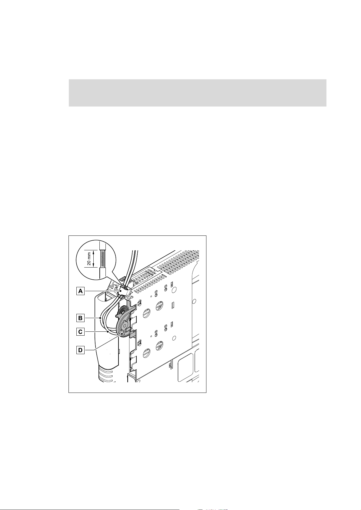
5.2.1 EMC-compliant wiring
In typical systems, standard shielding is sufficient for Ethernet cables.
However, in environments with a very high level of interference, EMC resistance can be improved
by earthing both sides of the cable shield as well.
For this purpose, observe the following notes:
1. The distance of the additional earthing from the Ethernet plug depends on the slot of the
module. The distance is:
• approx. 10 cm for the upper slot (MXI1)
• approx. 20 cm for the lower slot (MXI2)
2. Measure the appropriate distance along the cable and, starting from this point, remove 2 cm of
the cable's plastic sheath.
3. Fasten the cable shield to the shield sheet of the Servo Drive 9400.
A Fastening to the shield sheet of the Servo Drive
E94YCXX008
[5-3] EMC-compliant wiring
9400
B Outgoing EtherCAT line at X247 (OUT)
C IncomingEtherCAT line at X246 (IN)
D Communication module in slot MXI1 of the
Servo Drive 9400
24
Lenze · E94AYCET communication module (EtherCAT®) · Communication Manual · DMS 9.0 EN · 02/2014 · TD17
Page 25
5 Installation
M
SD
SD
SD
IN
INOUT
INOUT
M
S
SD
SD
M
IN IN
5.2 Electrical installation
_ _ _ _ _ _ _ _ _ _ _ _ _ _ _ _ _ _ _ _ _ _ _ _ _ _ _ _ _ _ _ _ _ _ _ _ _ _ _ _ _ _ _ _ _ _ _ _ _ _ _ _ _ _ _ _ _ _ _ _ _ _ _ _
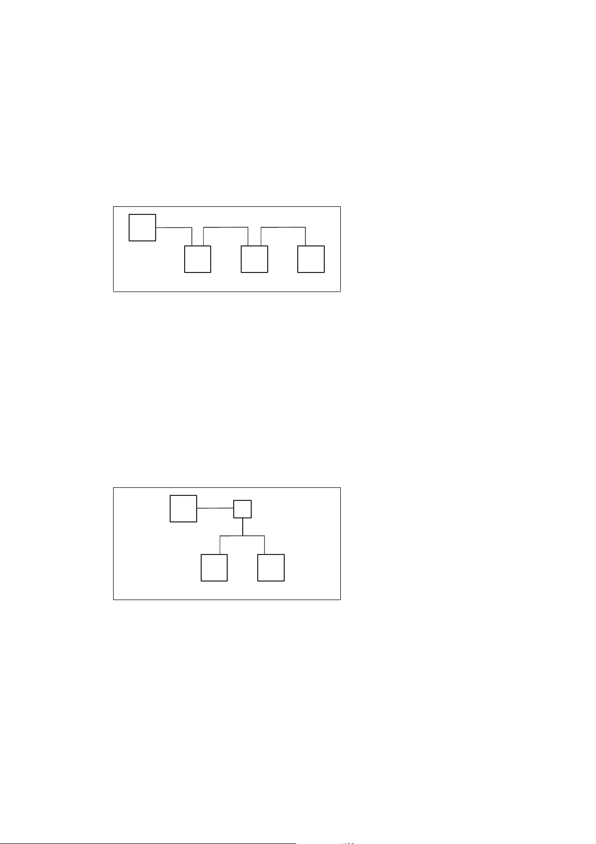
5.2.2 Network topology
An EtherCAT frame is sent through a pair of wires from the master to the slaves. The frame is
forwarded from slave to slave until it has passed through all the devices. Finally, the last slave
returns the frame to the master through a second pair of wires. In this way, EtherCAT always forms
a logic ring topology, irrespective of the topology used.
Line topology
M = master
SD = slave device
E94AYCET006
[5-4] Line topology
The devices are interconnected successively.
In order to ensure trouble-free operation, it is required to assign and wire the EtherCAT inputs (IN)
and EtherCAT outputs (OUT) correctly.
The receiving line is plugged into socket X246 (IN), the forwarding line into socket X247 (OUT).
The direction of data transmission is from the master to the slaves.
Tip!
The termination of the last EtherCAT node is effected automatically by the slave.
Switch topology
M = master
S = switch
SD = slave device
E94AYCET007
[5-5] Switch topology
The wiring can also be carried out in a star structure via an appropriate switch. For this, observe the
additional runtimes.
Lenze · E94AYCET communication module (EtherCAT®) · Communication Manual · DMS 9.0 EN · 02/2014 · TD17 25
Page 26
5 Installation
5.2 Electrical installation
_ _ _ _ _ _ _ _ _ _ _ _ _ _ _ _ _ _ _ _ _ _ _ _ _ _ _ _ _ _ _ _ _ _ _ _ _ _ _ _ _ _ _ _ _ _ _ _ _ _ _ _ _ _ _ _ _ _ _ _ _ _ _ _
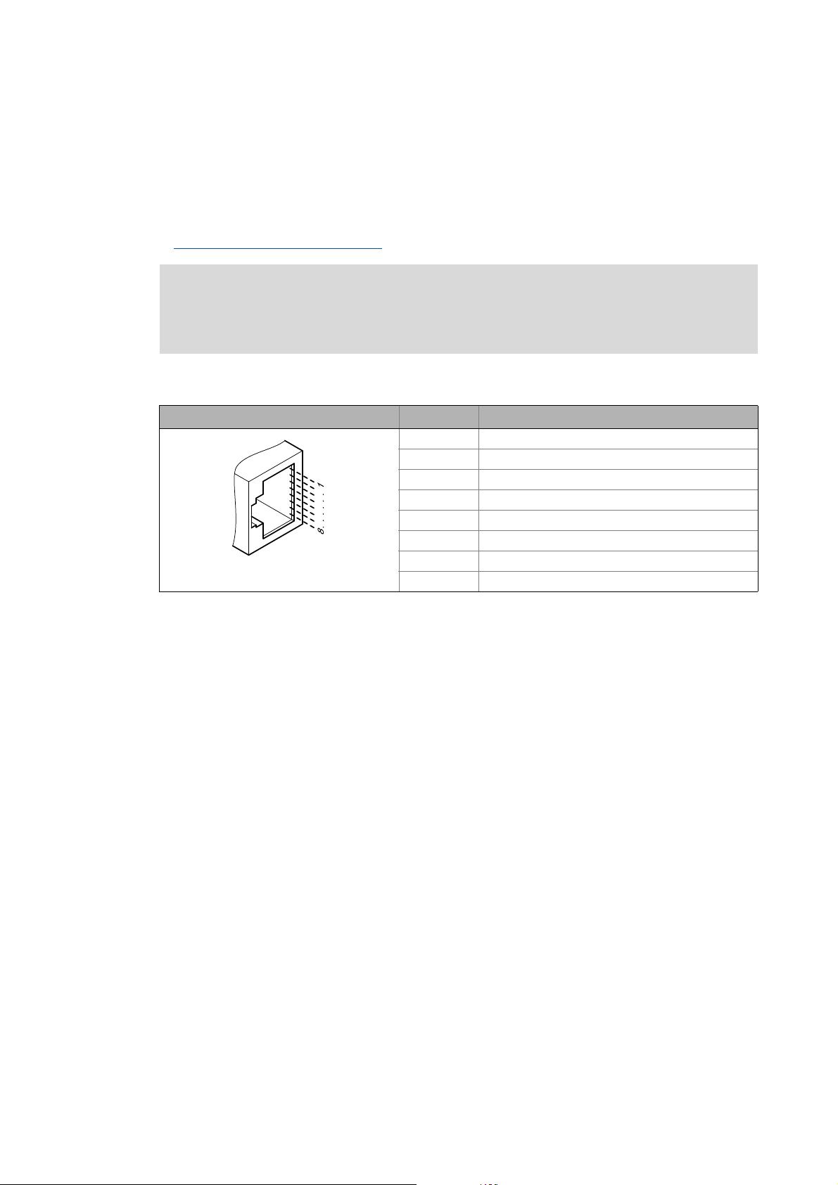
5.2.3 EtherCAT connection
The EtherCAT connection is established via the RJ45 sockets X246 (IN) and X247 (OUT).
A standard Ethernet patch cable is suitable for connecting the communication module to the
EtherCAT fieldbus.
Specification of the Ethernet cable
( 27)
Note!
In order to prevent damage to the RJ45 socket, plug or remove the Ethernet cable
connector straight (at a right angle) into/from the socket.
Pin assignment of the RJ45 sockets
RJ45 socket Pin Signal
1Tx +
2Tx -
3Rx +
4-
5-
6Rx -
E94AYCXX004C
7-
8-
Tip!
The EtherCAT interfaces are provided with an auto auto MDIX function. This function
adjusts the polarity of the RJ45 interfaces so that a connection can be established
irrespective of the polarity of the opposite EtherCAT interface and irrespective of the type
of cable used (standard patch cable or crossover cable).
26
Lenze · E94AYCET communication module (EtherCAT®) · Communication Manual · DMS 9.0 EN · 02/2014 · TD17
Page 27
5 Installation
5.2 Electrical installation
_ _ _ _ _ _ _ _ _ _ _ _ _ _ _ _ _ _ _ _ _ _ _ _ _ _ _ _ _ _ _ _ _ _ _ _ _ _ _ _ _ _ _ _ _ _ _ _ _ _ _ _ _ _ _ _ _ _ _ _ _ _ _ _
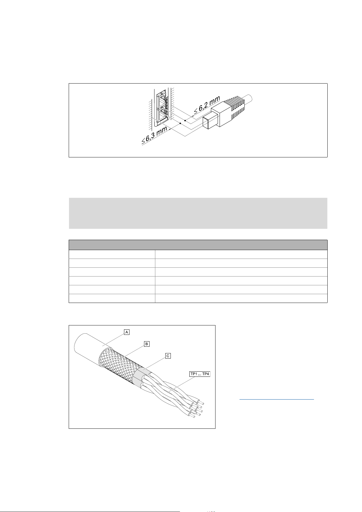
Mounting clearance
When ordering and using the Ethernet cable, observe the mounting clearances provided.
E94YCET017
[5-6] Mounting clearance
5.2.4 Specification of the Ethernet cable
Note!
Only use cables that correspond to the given specifications.
Specification of the Ethernet cable
Ethernet standard Standard Ethernet (acc. to IEEE 802.3), 100Base-TX (Fast Ethernet)
Cable type S/FTP (Screened Foiled Twisted Pair, ISO/IEC 11801 or EN 50173), CAT 5e
Damping 23.2 dB (for 100 MHz and 100 m each)
Crosstalk damping 24 dB (for 100 MHz and 100 m each)
Return loss 10 dB (100 m each)
Surge impedance 100
Structure of the Ethernet cable
A Cable insulation
B Braid
C Foil shielding
TP1
Twisted core pairs 1 ... 4
...
Colour code of the Ethernet cable
TP4
( 28)
E94YCEP016
[5-7] Structure of the Ethernet cable (S/FTP, CAT 5e)
Lenze · E94AYCET communication module (EtherCAT®) · Communication Manual · DMS 9.0 EN · 02/2014 · TD17 27
Page 28
5 Installation
5.2 Electrical installation
_ _ _ _ _ _ _ _ _ _ _ _ _ _ _ _ _ _ _ _ _ _ _ _ _ _ _ _ _ _ _ _ _ _ _ _ _ _ _ _ _ _ _ _ _ _ _ _ _ _ _ _ _ _ _ _ _ _ _ _ _ _ _ _
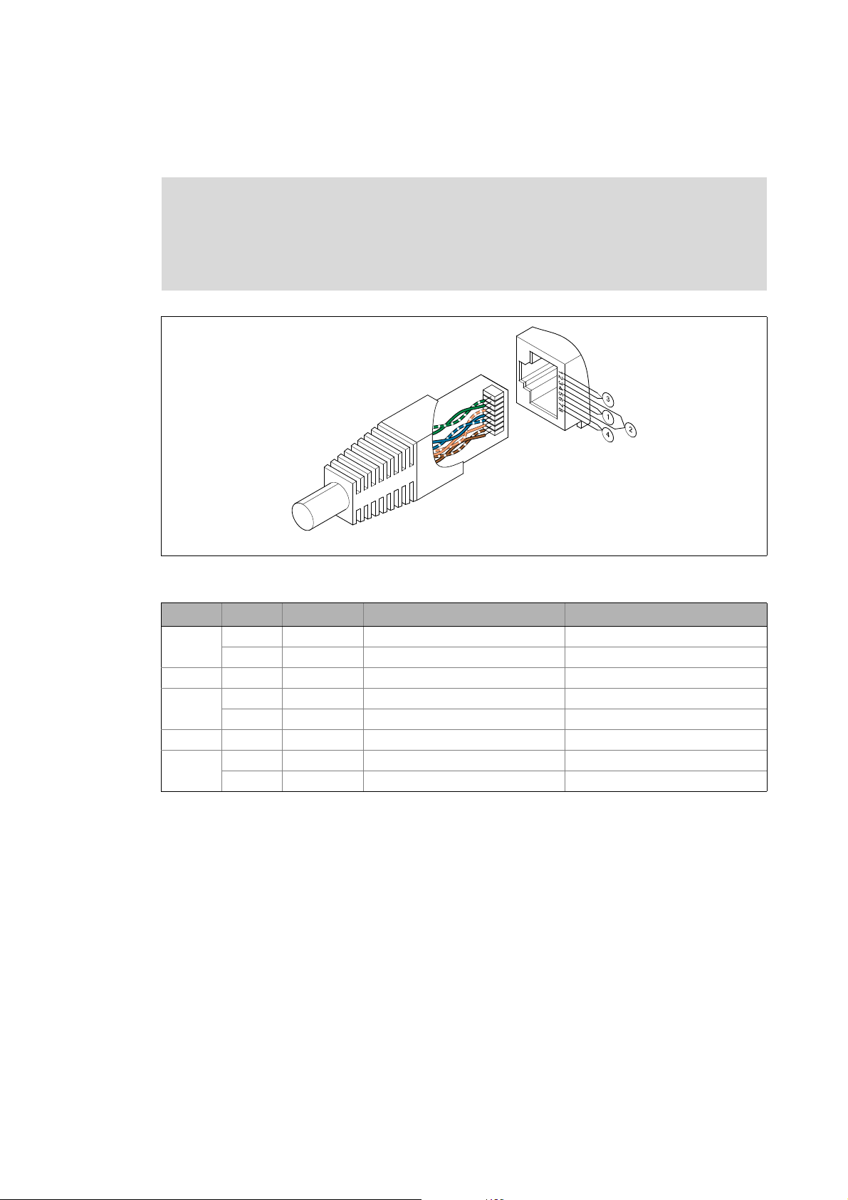
Colour code of the Ethernet cable
Note!
Wiring and colour code are standardised in EIA/TIA 568A/568B.
The use of 4-pole Ethernet cables according to industrial standard is permissible. The
cable type only connects the assigned pins 1, 2, 3 and 6.
E94YCEI004A
[5-8] Ethernet plugs in accordance with EIA/TIA 568A/568B
Pair Pin Signal EIA/TIA 568A EIA/TIA 568B
3 1 Tx + white / green white / orange
2 Tx - green orange
2 3 Rx + white / orange white / green
1 4 blue blue
5 white / blue blue / white
2 6 Rx - orange green
4 7 white / brown white / brown
8brown brown
28
Lenze · E94AYCET communication module (EtherCAT®) · Communication Manual · DMS 9.0 EN · 02/2014 · TD17
Page 29
5 Installation
5.2 Electrical installation
_ _ _ _ _ _ _ _ _ _ _ _ _ _ _ _ _ _ _ _ _ _ _ _ _ _ _ _ _ _ _ _ _ _ _ _ _ _ _ _ _ _ _ _ _ _ _ _ _ _ _ _ _ _ _ _ _ _ _ _ _ _ _ _
5.2.5 External voltage supply
The communication module can be supplied externally with voltage via separate supply cables at
the 2-pole plug connector X245.
Note!
With external voltage supply, always use a separate power supply unit, safely separated
to EN 61800-5-1 in every control cabinet (SELV/PELV).
External voltage supply of the communication module is necessary if the bus communication is to
be continued in the event of a failure of the supply of the standard device.
Access to parameters of a standard device disconnected from the mains is not possible.
Assignment of the X245 plug connector
Designation Description
+ U = 24 V DC (20.4 V -0 % ... 28.8 V +0 %)
I = 130 mA
- Reference potential for the external voltage supply
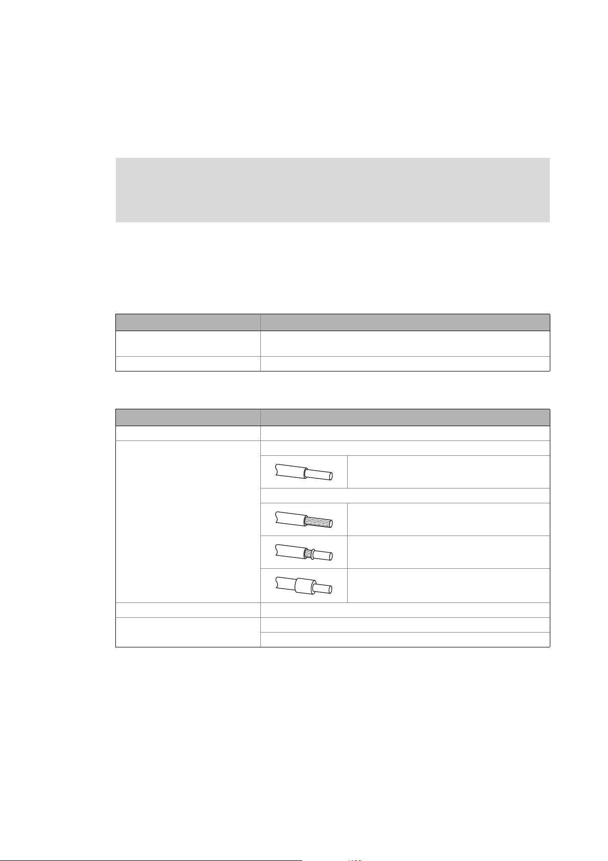
Terminal data
Area Values
Electrical connection 2-pole plug connector (spring connection/screw connection)
Possible connections Fixed:
2
1.5 mm
Flexible:
Without wire end ferrule
1.5 mm
With wire end ferrule, without plastic sleeve
1.5 mm
With wire end ferrule, with plastic sleeve
0.5 mm
Starting torque 0.5 ... 0.6 Nm / 4.4 ... 5.3 lb-in (only with screw connection)
Stripping length 6 mm with screw connection
9 mm with spring connection
(AWG 16)
2
(AWG 16)
2
(AWG 16)
2
(AWG20)
Lenze · E94AYCET communication module (EtherCAT®) · Communication Manual · DMS 9.0 EN · 02/2014 · TD17 29
Page 30

6 Commissioning
6.1 Before initial switch-on
_ _ _ _ _ _ _ _ _ _ _ _ _ _ _ _ _ _ _ _ _ _ _ _ _ _ _ _ _ _ _ _ _ _ _ _ _ _ _ _ _ _ _ _ _ _ _ _ _ _ _ _ _ _ _ _ _ _ _ _ _ _ _ _
6 Commissioning
During commissioning, plant-specific data such as motor parameters, operating parameters,
responses, and parameters for fieldbus communication are defined for the drive. Lenze devices use
codes for this purpose.
The codes of the drive and for communication are saved to the memory module in a non-volatile
data set.
In addition, there are codes for diagnosing and monitoring the stations.
Note!
When parameterising the communication module, please observe that the code number
depends on the slot of the Servo Drive 9400 in which the communication module has
been inserted.
The first two digits of the code number specify the slot:
•C13nnn for slot MXI1
Parameters of the communication module for slot MXI1
•C14nnn for slot MXI2
Parameters of the communication module for slot MXI2
You also have to set the Communication-relevant parameters of the standard device
( 94)
.
( 97)
( 114)
6.1 Before initial switch-on
Stop!
Before you switch on the Servo Drive 9400 and the communication module for the first
time, check the entire wiring for completeness, short circuit and earth fault.
30
Lenze · E94AYCET communication module (EtherCAT®) · Communication Manual · DMS 9.0 EN · 02/2014 · TD17
Page 31

6 Commissioning
6.2 Configuring the controller (EtherCAT master)
_ _ _ _ _ _ _ _ _ _ _ _ _ _ _ _ _ _ _ _ _ _ _ _ _ _ _ _ _ _ _ _ _ _ _ _ _ _ _ _ _ _ _ _ _ _ _ _ _ _ _ _ _ _ _ _ _ _ _ _ _ _ _ _
6.2 Configuring the controller (EtherCAT master)
The controller (EtherCAT master) must be configured before communication with the
communication module is possible.
In order to configure EtherCAT networks, you always need a configuration software for the
controller, e.g.:
• Lenze »PLC Designer«
• Beckhoff »TwinCAT«
These are software systems for the programming of control programs, EtherCAT configuration, realtime execution, and diagnostics.
The basic parameters of the communication module are stored in the internal configuration
memory and can be used by the master for the node identification.
For the node search (fieldbus scan), the corresponding device descriptions of the Lenze device family
are used.
"Controller-based Automation EtherCAT" communication manual
Here you'll find some detailed information relating to the EtherCAT configuration with
the Lenze »PLC Designer«.
6.2.1 Installing device description files
The current XML device description files required for configuring the EtherCAT node can be found in
the download area at:
www.lenze.com
The following device description file can be installed via the EtherCAT configuration software.
Device description file Used for ...
Lenze_E94AYCET_V100_yymmdd.xml Firmware version 1.01 of the E94AYCET communication
Lenze_E94AYCET_IO_yyyymmdd.xml From firmware version 2.0 of the E94AYCET
Lenze_E94AYCET_MOTION_yyyymmdd.xml From firmware version 2.0 of the communication
Wildcards in the file name
yyyy Year
mm Month
dd Day
module
communication module onwards, in connection with the
"CiA402" technology application and Servo Drives 9400
module E94AYCET in connection with Servo Drives 9400
Lenze · E94AYCET communication module (EtherCAT®) · Communication Manual · DMS 9.0 EN · 02/2014 · TD17 31
Page 32

6 Commissioning
6.2 Configuring the controller (EtherCAT master)
_ _ _ _ _ _ _ _ _ _ _ _ _ _ _ _ _ _ _ _ _ _ _ _ _ _ _ _ _ _ _ _ _ _ _ _ _ _ _ _ _ _ _ _ _ _ _ _ _ _ _ _ _ _ _ _ _ _ _ _ _ _ _ _
6.2.2 Automatic device identification
For a faultless integration of the EtherCAT slaves slaves into a master configuration it is necessary
to select the correct Lenze device in the EtherCAT configuration software.
Each EtherCAT node is identified unambiguously by the configuration software by means of the
product code (equal to the CoE object I-1018.2), the manufacturer's identification mark (0x3B), and
the main software version of the communication module.
Identification
( 12)
Implemented CoE objects
( 79)
In order that the configuration software selects the configuration specific for the EtherCAT node
from the device description file, the product code is automatically set in the identity object
according to the technology application selected in the drive (code C00218) and is updated after the
voltage supply is switched off/on or after every application download.
During initialisation, the product code is transferred to the EtherCAT master. On the basis of this
identification, the master can accept the corresponding settings from the device description.
Product codes for Servo Drives 9400
The product code defines the following devices in the device description files, depending on the
technology application selected in the Servo Drive 9400:
Product code [dec] Meaning
9 4 0 0 2 3 x x x Servo Drive 9400 HighLine
Applications:
0 0 0 Empty application (appl. ID 100000000)
0 0 1 Actuating drive speed (appl. ID 100102101)
0 0 2 Actuating drive torque (appl. ID 100202101)
0 0 3 Electronic gearbox (appl. ID 100302202 /100302102)
0 0 4 Synchronism with mark synchronisation
(appl. ID 100402202 / 100402102)
0 0 5 Table positioning (appl. ID 100502101)
0 0 6 Positioning sequence control (appl. ID 100602103)
1 0 1 CiA402 (appl. ID 110102102)
32
9 4 0 0 2 5 0 0 7 Servo Drive 9400 PLC
with PLC application (appl. ID 100700204)
9 4 0 0 2 6 2 0 1 Servo Drive 9400 V/R (regenerative power supply module)
with V/R application (appl. ID 120100101)
Lenze · E94AYCET communication module (EtherCAT®) · Communication Manual · DMS 9.0 EN · 02/2014 · TD17
Page 33

6 Commissioning
6.2 Configuring the controller (EtherCAT master)
_ _ _ _ _ _ _ _ _ _ _ _ _ _ _ _ _ _ _ _ _ _ _ _ _ _ _ _ _ _ _ _ _ _ _ _ _ _ _ _ _ _ _ _ _ _ _ _ _ _ _ _ _ _ _ _ _ _ _ _ _ _ _ _
6.2.3 Configuring process data
Servo Drives 9400 support the configuration of max. 32 process data words (max. 64 bytes) per
direction.
The process data configuration is determined during the initialisation phase of the master (PDO
mapping).
The process data configuration is specifically predefined in the device description file for each
application.
The process data length can be adapted by the user, if required.
6.2.4 Determining the cycle time
The process data objects (PDO) are transmitted cyclically between the EtherCAT master and the
slaves (drives).
The cycle time is set by means of the EtherCAT configuration software.
Lenze · E94AYCET communication module (EtherCAT®) · Communication Manual · DMS 9.0 EN · 02/2014 · TD17 33
Page 34

6 Commissioning
6.3 Address allocation
_ _ _ _ _ _ _ _ _ _ _ _ _ _ _ _ _ _ _ _ _ _ _ _ _ _ _ _ _ _ _ _ _ _ _ _ _ _ _ _ _ _ _ _ _ _ _ _ _ _ _ _ _ _ _ _ _ _ _ _ _ _ _ _
6.3 Address allocation
The EtherCAT nodes are normally addressed via a fixed 16-bit address defined by the EtherCAT
master. During start-up, the master assigns this address to each node, depending on the physical
order in the EtherCAT network. The address is not saved and is lost when the device is switched off.
In the »Engineer«, the address assigned is shown under the Settings tab in the Active station
address display field (C13864
/ C14864).
Define station alias
Via the Station alias address input field, you can also assign a permanent address to the
EtherCAT slave.
Note!
• The station alias must only be set if the node is part of a "hot connect" group.
• The station alias must be unambiguous and must only be assigned once within the
EtherCAT network.
• Use the same station alias in the EtherCAT master and in the slave.
Valid address range: 0 … 32767
• Address '0' means that no station alias is assigned.
• Impermissible addresses are marked in red in the input field.
• The address is written to code C13899
In addition, specify the use of the fixed addressing on the master.
/ C14899.
34
Lenze · E94AYCET communication module (EtherCAT®) · Communication Manual · DMS 9.0 EN · 02/2014 · TD17
Page 35

6 Commissioning
6.4 Synchronisation with "Distributed Clocks" (DC)
_ _ _ _ _ _ _ _ _ _ _ _ _ _ _ _ _ _ _ _ _ _ _ _ _ _ _ _ _ _ _ _ _ _ _ _ _ _ _ _ _ _ _ _ _ _ _ _ _ _ _ _ _ _ _ _ _ _ _ _ _ _ _ _
6.4 Synchronisation with "Distributed Clocks" (DC)
The "Distributed clocks" (DC) functionality enables exact time synchronisation for applications in
which several axes perform a coordinated movement simultaneously. Data are incorporated
synchronously with the PLC program. During DC synchronisation, all slaves are synchronised with a
reference clock, the so-called "DC master".
Note!
• DC synchronisation is absolutely required for Motion applications.
• DC synchronisation can also be used for Logic applications.
• Not all slaves support the DC functionality.
• On order to be able to use the DC functionality, the first slave connected to the
EtherCAT master (e.g. Lenze Controller) must have DC master capability.
When further slaves are connected, DC-capable and non-DC-capable devices can be
mixed.
• The first EtherCAT slave after the Lenze Controller must
supplies the other EtherCAT nodes (incl. the controller) with the exact time.
be the DC master that
[6-1] Example: "Distributed clocks" in the EtherCAT bus system with Lenze Controller 3231 C
The DC synchronisation is set with the EtherCAT configuration software (e.g. »PLC Designer«,
»TwinCAT«).
"Controller-based Automation EtherCAT" communication manual
Here you'll find some detailed information relating to the EtherCAT configuration with
the Lenze »PLC Designer«.
Lenze · E94AYCET communication module (EtherCAT®) · Communication Manual · DMS 9.0 EN · 02/2014 · TD17 35
Page 36

6 Commissioning
6.4 Synchronisation with "Distributed Clocks" (DC)
_ _ _ _ _ _ _ _ _ _ _ _ _ _ _ _ _ _ _ _ _ _ _ _ _ _ _ _ _ _ _ _ _ _ _ _ _ _ _ _ _ _ _ _ _ _ _ _ _ _ _ _ _ _ _ _ _ _ _ _ _ _ _ _
6.4.1 DC configuration in the master
By default, the application of the DC synchronisation is deactivated in the device description ( 31).
Parameterise the DC synchronisation in the EtherCAT configuration software (e.g. »PLC Designer«,
»TwinCAT«).
Set the synchronisation cycle time in the master. It is mainly defined by the processing time of the
master and the slaves.
Note!
The synchronisation cycle time ...
• must be an integer multiple of 1 ms;
• may be maximally 15 ms.
36
Lenze · E94AYCET communication module (EtherCAT®) · Communication Manual · DMS 9.0 EN · 02/2014 · TD17
Page 37

6 Commissioning
6.4 Synchronisation with "Distributed Clocks" (DC)
_ _ _ _ _ _ _ _ _ _ _ _ _ _ _ _ _ _ _ _ _ _ _ _ _ _ _ _ _ _ _ _ _ _ _ _ _ _ _ _ _ _ _ _ _ _ _ _ _ _ _ _ _ _ _ _ _ _ _ _ _ _ _ _
6.4.2 DC configuration in the Servo Drive 9400 (slave)
Note!
The settings of the parameter sync cycle time (C01121), sync phase position (C01122),
sync tolerance (C01123), and sync PLL increment (C01124) common for the Lenze system
bus (CAN), cannot be made for EtherCAT. These values are automatically calculated by
the EtherCAT communication module and are set internally in the drive.
In order to be able to use the DC synchronisation in the Servo Drive 9400, go to the Settings tab in
the Sync source selection field and select the sync source (C01120
• Selection 4: Module in slot MXI1 of the Servo Drive 9400
• Selection 5: Module in slot MXI2 of the Servo Drive 9400
):
Lenze · E94AYCET communication module (EtherCAT®) · Communication Manual · DMS 9.0 EN · 02/2014 · TD17 37
Page 38

6 Commissioning
6.4 Synchronisation with "Distributed Clocks" (DC)
_ _ _ _ _ _ _ _ _ _ _ _ _ _ _ _ _ _ _ _ _ _ _ _ _ _ _ _ _ _ _ _ _ _ _ _ _ _ _ _ _ _ _ _ _ _ _ _ _ _ _ _ _ _ _ _ _ _ _ _ _ _ _ _
6.4.3 Response of the Lenze EtherCAT nodes during start-up
Code C13883 / C14883 shows whether the DC synchronisation has been activated for the
communication module.
If the DC synchronisation is used, the communication module only changes to the "Operational"
state when the standard device has adapted its phase position to the DC signal. This process may
take several seconds.
Note!
• If the communication module does not change to the "Operational" state, there might
be an error in the configuration or in the EtherCAT wiring.
• The communication module compares the cycle time defined by the EtherCAT master
to the internal processing time (1 ms) of the standard device. The synchronisation
cycle time in the master must be identical with or an integer multiple of 1 ms.
• Furthermore it is checked whether the sync source selection in standard device code
C01120
• Further information can be found in the status information or emergency messages
of the master.
is correct.
The cycle time (in μs) set by the master on the fieldbus is displayed with code C13870
The state of the standard device synchronicity is displayed in code C13884
/ C14884.
/ C14870.
38
Lenze · E94AYCET communication module (EtherCAT®) · Communication Manual · DMS 9.0 EN · 02/2014 · TD17
Page 39

6 Commissioning
6.4 Synchronisation with "Distributed Clocks" (DC)
_ _ _ _ _ _ _ _ _ _ _ _ _ _ _ _ _ _ _ _ _ _ _ _ _ _ _ _ _ _ _ _ _ _ _ _ _ _ _ _ _ _ _ _ _ _ _ _ _ _ _ _ _ _ _ _ _ _ _ _ _ _ _ _
6.4.4 Process data mode
Code C13892 / C14892 serves to influence the internal PDO processing time of the actual values.
Determinististic mode (C13892
In the deterministic mode, the actual values are copied to the EtherCAT interface with the next
Sync0 event.
Optimised mode (C13892
In the optimised mode, the actual values are not copied to the EtherCAT interface with the next
Sync0 event but already 320 μs after the last Sync0 event. Thus, the actual values are provided one
cycle earlier in the EtherCAT interface.
Conditions for the optimised mode:
• The EtherCAT frame generated by the master has a low jitter and is sent within a window of
320 μs after the Sync0 and shortly before the next Sync0 event.
• The EtherCAT cycle time must be 1 ms.
/ C14892 =1, Lenze setting)
/ C14892 =0)
Note!
• The process data mode is only evaluated with DC synchronisation.
• The setpoints are always processed with the Sync0 event.
• When Lenze EtherCAT controllers are used, we recommend setting the deterministic
mode (C13892
/ C14892 = 1).
Lenze · E94AYCET communication module (EtherCAT®) · Communication Manual · DMS 9.0 EN · 02/2014 · TD17 39
Page 40

6 Commissioning
6.5 Establishing an online connection with the »Engineer«
_ _ _ _ _ _ _ _ _ _ _ _ _ _ _ _ _ _ _ _ _ _ _ _ _ _ _ _ _ _ _ _ _ _ _ _ _ _ _ _ _ _ _ _ _ _ _ _ _ _ _ _ _ _ _ _ _ _ _ _ _ _ _ _
6.5 Establishing an online connection with the »Engineer«
With the »Engineer« you can establish an online connection to the individual field devices.
When an online connection has been established, you can for instance carry out parameter settings
directly in the field device or diagnose the field device.
Stop!
If parameters in the »Engineer« are changed while the Engineer is connected online to
the field device, the changes are directly accepted to the device!
Note!
To go online, the EtherCAT bus at least has to be in the "Pre-Operational" state.
The functions for establishing/cancelling an online connection in the »Engineer« can be executed
via the Online menu:
Menu command Shortcut
Online Go online <F4>
Online Set communication path and go online
Configuring a bus connection:
• Gateway controller -> configure EtherCAT
• Gateway controller -> configure EtherCAT ADS (Beckhoff)
Online Go offline <Shift>+<F4>
( 41)
( 43)
Documentation for the Lenze »Engineer«
Here you'll find further detailed information about how to establish an online
connection.
40
Lenze · E94AYCET communication module (EtherCAT®) · Communication Manual · DMS 9.0 EN · 02/2014 · TD17
Page 41

6 Commissioning
6.5 Establishing an online connection with the »Engineer«
_ _ _ _ _ _ _ _ _ _ _ _ _ _ _ _ _ _ _ _ _ _ _ _ _ _ _ _ _ _ _ _ _ _ _ _ _ _ _ _ _ _ _ _ _ _ _ _ _ _ _ _ _ _ _ _ _ _ _ _ _ _ _ _
6.5.1 Gateway controller -> configure EtherCAT
The Lenze controller provides a gateway function to establish an online connection to a field device
via EtherCAT.
[6-2] Example: EtherCAT bus system with a Lenze Controller 3231 C as gateway
Lenze · E94AYCET communication module (EtherCAT®) · Communication Manual · DMS 9.0 EN · 02/2014 · TD17 41
Page 42

6 Commissioning
6.5 Establishing an online connection with the »Engineer«
_ _ _ _ _ _ _ _ _ _ _ _ _ _ _ _ _ _ _ _ _ _ _ _ _ _ _ _ _ _ _ _ _ _ _ _ _ _ _ _ _ _ _ _ _ _ _ _ _ _ _ _ _ _ _ _ _ _ _ _ _ _ _ _
How to configure an online connection to a field device which is connected to the Lenze
Controller via EtherCAT:
1. Go to the "Communication path" dialog box and select the entry "Gateway controller ->
EtherCAT" from the "Bus connection" list field.
2. Click Search/Enter....
The "Gateway Controller -> Set up EtherCAT bus" dialog box is shown:
3. Enter the IP address of the controller.
By clicking the Ping button, you can carry out a simple test which verifies whether a device
can actually be reached via the IP address set.
4. Click OK.
• The "Enter IP address" dialog box is closed.
•In the Device access path column of the "Communication path" dialog box, the
corresponding device access path is shown
(e.g. "IPC:172_31_207_254.ECAT.ecat1.dev1001.").
42
Lenze · E94AYCET communication module (EtherCAT®) · Communication Manual · DMS 9.0 EN · 02/2014 · TD17
Page 43

6 Commissioning
6.5 Establishing an online connection with the »Engineer«
_ _ _ _ _ _ _ _ _ _ _ _ _ _ _ _ _ _ _ _ _ _ _ _ _ _ _ _ _ _ _ _ _ _ _ _ _ _ _ _ _ _ _ _ _ _ _ _ _ _ _ _ _ _ _ _ _ _ _ _ _ _ _ _
6.5.2 Gateway controller -> configure EtherCAT ADS (Beckhoff)
The Gateway EtherCAT ADS bus connection makes it possible to establish an online connection to a
Lenze drive that is connected to a Beckhoff controller via EtherCAT (gateway function).
[6-3] Example: EtherCAT bus system with a Beckhoff controller as Gateway
How to configure an online connection to a field device which is connected to a Beckhoff
controller via EtherCAT:
1. Highlight the project root in the project.
Alternatively: Create a new project or carry out a fieldbus scan.
2. Execute the menu command Insert Insert device detected online.
3. Select Gateway Controller -> EtherCAT ADS as bus connection.
4. Configure access data:
• Configure the access data applicable to the controller via the Insert address button.
•The Search button initiates the controller to display the fieldbus nodes connected to the
EtherCAT segment.
Lenze · E94AYCET communication module (EtherCAT®) · Communication Manual · DMS 9.0 EN · 02/2014 · TD17 43
Page 44

6 Commissioning
6.5 Establishing an online connection with the »Engineer«
_ _ _ _ _ _ _ _ _ _ _ _ _ _ _ _ _ _ _ _ _ _ _ _ _ _ _ _ _ _ _ _ _ _ _ _ _ _ _ _ _ _ _ _ _ _ _ _ _ _ _ _ _ _ _ _ _ _ _ _ _ _ _ _
How to use the EtherCAT ADS communication path:
1. Highlight the desired drive, to which a gateway connection via EtherCAT ADS is to be
established, in the project tree.
2. Call the menu command Online Set communication path and go online.
3. Select Gateway Controller -> EtherCAT ADS as bus connection.
4. Enter the access data applicable to the controller in area .
Enter the user name, password, and the IP address and the AMS Net ID of the EtherCAT
interface of the controller.
5. In area , specify the EtherCAT address of the field device to which the online connection
is to be established.
Alternatively you can click the Search/Enter button which calls the "Select Device Access
Path" dialog box. By this, the »Engineer« initiates the controller to display the devices
detected on the EtherCAT segment.
44
Lenze · E94AYCET communication module (EtherCAT®) · Communication Manual · DMS 9.0 EN · 02/2014 · TD17
Page 45

6 Commissioning
6.6 EtherCAT ADS communication parameters in »TwinCAT« and »Engineer«
_ _ _ _ _ _ _ _ _ _ _ _ _ _ _ _ _ _ _ _ _ _ _ _ _ _ _ _ _ _ _ _ _ _ _ _ _ _ _ _ _ _ _ _ _ _ _ _ _ _ _ _ _ _ _ _ _ _ _ _ _ _ _ _
6.6 EtherCAT ADS communication parameters in »TwinCAT« and »Engineer«
In the following, two example structures are used to describe where you can find the EtherCAT ADS
communication parameters in the Beckhoff »TwinCAT« and in the Lenze »Engineer«EtherCAT.
6.6.1 Example: Structure without a Beckhoff controller
[6-4] Example: EtherCAT bus system without Beckhoff controller
The Beckhoff Soft-PLC runs on the Microsoft Windows XP PC on which the Beckhoff »TwinCAT« and
the Lenze »Engineer« are installed as well.
Display of the communication parameters in »TwinCAT«
The communication parameters IP address (here ’172.31.200.200’) and EtherCAT Master
Net ID (here ’172.31.200.200.2.1’) can be found under the target system selection:
Lenze · E94AYCET communication module (EtherCAT®) · Communication Manual · DMS 9.0 EN · 02/2014 · TD17 45
Page 46

6 Commissioning
6.6 EtherCAT ADS communication parameters in »TwinCAT« and »Engineer«
_ _ _ _ _ _ _ _ _ _ _ _ _ _ _ _ _ _ _ _ _ _ _ _ _ _ _ _ _ _ _ _ _ _ _ _ _ _ _ _ _ _ _ _ _ _ _ _ _ _ _ _ _ _ _ _ _ _ _ _ _ _ _ _
The EtherCAT Slave address (here ’1001’) can be found under the EtherCAT tab of the
EtherCAT slave:
46
Lenze · E94AYCET communication module (EtherCAT®) · Communication Manual · DMS 9.0 EN · 02/2014 · TD17
Page 47

6 Commissioning
6.6 EtherCAT ADS communication parameters in »TwinCAT« and »Engineer«
_ _ _ _ _ _ _ _ _ _ _ _ _ _ _ _ _ _ _ _ _ _ _ _ _ _ _ _ _ _ _ _ _ _ _ _ _ _ _ _ _ _ _ _ _ _ _ _ _ _ _ _ _ _ _ _ _ _ _ _ _ _ _ _
Online device identification in the »Engineer« start-up wizard
In the »Engineer« start-up wizard under the Gateway Controller -> EtherCAT ADS bus
connection, a field device was detected online:
IP address: 172.31.200.200
EtherCAT Net ID: 172.31.200.200.2.1
EtherCAT slave address: 1001
Lenze · E94AYCET communication module (EtherCAT®) · Communication Manual · DMS 9.0 EN · 02/2014 · TD17 47
Page 48

6 Commissioning
6.6 EtherCAT ADS communication parameters in »TwinCAT« and »Engineer«
_ _ _ _ _ _ _ _ _ _ _ _ _ _ _ _ _ _ _ _ _ _ _ _ _ _ _ _ _ _ _ _ _ _ _ _ _ _ _ _ _ _ _ _ _ _ _ _ _ _ _ _ _ _ _ _ _ _ _ _ _ _ _ _
Display of the identification of the field device detected in the »Engineer« start-up wizard:
IP address: 172.31.200.200
EtherCAT Net ID: 172.31.200.200.2.1
EtherCAT slave address: 1001
48
Lenze · E94AYCET communication module (EtherCAT®) · Communication Manual · DMS 9.0 EN · 02/2014 · TD17
Page 49

6 Commissioning
6.6 EtherCAT ADS communication parameters in »TwinCAT« and »Engineer«
_ _ _ _ _ _ _ _ _ _ _ _ _ _ _ _ _ _ _ _ _ _ _ _ _ _ _ _ _ _ _ _ _ _ _ _ _ _ _ _ _ _ _ _ _ _ _ _ _ _ _ _ _ _ _ _ _ _ _ _ _ _ _ _
6.6.2 Example: Structure with a Beckhoff DIN rail IPC CX1020
[6-5] Example: EtherCAT bus system with Beckhoff controller
A Beckhoff DIN rail IPC with the Microsoft Windows CE operating system is used.
The Beckhoff »TwinCAT« and the Lenze »Engineer« are installed on a Windows XP PC.
Display of the communication parameters in »TwinCAT«
The communication parameters IP address (here ’172.31.200.10’) and EtherCAT Master
Net ID (here ’5.3.66.236.4.1’) can be found under the target system selection:
Lenze · E94AYCET communication module (EtherCAT®) · Communication Manual · DMS 9.0 EN · 02/2014 · TD17 49
Page 50

6 Commissioning
6.6 EtherCAT ADS communication parameters in »TwinCAT« and »Engineer«
_ _ _ _ _ _ _ _ _ _ _ _ _ _ _ _ _ _ _ _ _ _ _ _ _ _ _ _ _ _ _ _ _ _ _ _ _ _ _ _ _ _ _ _ _ _ _ _ _ _ _ _ _ _ _ _ _ _ _ _ _ _ _ _
The EtherCAT Master Net ID (here ’5.3.66.236.4.1’) can also be found under the EtherCAT tab of
the EtherCAT master:
The EtherCAT slave address (here ’1003’) can be found under the EtherCAT tab of the
EtherCAT slave:
50
Lenze · E94AYCET communication module (EtherCAT®) · Communication Manual · DMS 9.0 EN · 02/2014 · TD17
Page 51

6 Commissioning
6.6 EtherCAT ADS communication parameters in »TwinCAT« and »Engineer«
_ _ _ _ _ _ _ _ _ _ _ _ _ _ _ _ _ _ _ _ _ _ _ _ _ _ _ _ _ _ _ _ _ _ _ _ _ _ _ _ _ _ _ _ _ _ _ _ _ _ _ _ _ _ _ _ _ _ _ _ _ _ _ _
Online device identification in the »Engineer« start-up wizard
In the »Engineer« start-up wizard under the Gateway Controller -> EtherCAT ADS bus
connection, a field device was detected online:
IP address: 172.31.200.10
EtherCAT Net ID: 5.3.66.236.4.1
EtherCAT slave address: 1003
Lenze · E94AYCET communication module (EtherCAT®) · Communication Manual · DMS 9.0 EN · 02/2014 · TD17 51
Page 52

6 Commissioning
6.6 EtherCAT ADS communication parameters in »TwinCAT« and »Engineer«
_ _ _ _ _ _ _ _ _ _ _ _ _ _ _ _ _ _ _ _ _ _ _ _ _ _ _ _ _ _ _ _ _ _ _ _ _ _ _ _ _ _ _ _ _ _ _ _ _ _ _ _ _ _ _ _ _ _ _ _ _ _ _ _
Display of the identification of the field device detected in the »Engineer« start-up wizard:
IP address: 172.31.200.10
EtherCAT Net ID: 5.3.66.236.4.1
EtherCAT slave address: 1003
52
Lenze · E94AYCET communication module (EtherCAT®) · Communication Manual · DMS 9.0 EN · 02/2014 · TD17
Page 53

6 Commissioning
6.7 Initial switch-on
_ _ _ _ _ _ _ _ _ _ _ _ _ _ _ _ _ _ _ _ _ _ _ _ _ _ _ _ _ _ _ _ _ _ _ _ _ _ _ _ _ _ _ _ _ _ _ _ _ _ _ _ _ _ _ _ _ _ _ _ _ _ _ _
6.7 Initial switch-on
Documentation of Servo Drive 9400
Observe the safety instructions and residual hazards stated.
Note!
Establishing communication
In order to establish communication via an externally supplied communication module,
the standard device must be switched on as well.
After communication has been established, the externally supplied module operates
independently of the power on/off state of the standard device.
Activating changed settings
In order to activate changed settings ...
• execute device command "11: Save start parameters" via standard device code
C00002 and ...
• then execute a "reset node" of the node or switch off the voltage supply of the
communication module and switch it on again.
Protection against uncontrolled restart
After a fault (e.g. short-time mains failure), the restart of a drive is not always wanted
and - in some cases - even not allowed.
In the Lenze setting of the Servo Drives 9400, the restart protection is activated.
Via the standard device code C00142 ("Auto restart after mains connection") you can set
the restart behaviour of the drive:
C00142 = "0: Inhibited" (Lenze setting)
• The drive remains inhibited (even if the fault is no longer active).
• The drive starts in a controlled mode by explicitly enabling the drive: LOW-HIGH edge
at digital input X5/RFR.
C00142 = "1: enabled"
• An uncontrolled restart of the drive is possible.
Lenze · E94AYCET communication module (EtherCAT®) · Communication Manual · DMS 9.0 EN · 02/2014 · TD17 53
Page 54

7 Data transfer
_ _ _ _ _ _ _ _ _ _ _ _ _ _ _ _ _ _ _ _ _ _ _ _ _ _ _ _ _ _ _ _ _ _ _ _ _ _ _ _ _ _ _ _ _ _ _ _ _ _ _ _ _ _ _ _ _ _ _ _ _ _ _ _
7 Data transfer
Compared with conventional Ethernet, the collision-free transfer of frames on the fieldbus makes
EtherCAT a real-time capable bus system.
Communication is always initiated by the EtherCAT master, e.g. a Lenze Controller. A frame sent by
the master passes through all EtherCAT slaves. The last slave of the communication chain sends the
frame back to the EtherCAT master. On the way back, the frame is directly sent to the master,
without being processed in the slaves.
EtherCAT transmits data in so-called "EtherCAT frames". The EtherCAT nodes only extract the data
intended for them while the EtherCAT frame passes through the device. At the same time output
data are inserted into the frame while it passes through the device. Read and write accesses are only
executed on a small section of the entire EtherCAT frame – the datagrams. Therefore it is not
necessary to receive the complete frame before it can be processed. Processing starts as soon as
possible.
EtherCAT transmits process data, parameter data, configuration data, and diagnostic data between
the EtherCAT master and the drives (slaves) that are part of the fieldbus. The data are transmitted
via corresponding communication channels depending on their time-critical behaviour (see Process
data transfer ( 59) / Parameter data transfer ( 68)).
54 Lenze · E94AYCET communication module (EtherCAT®) · Communication Manual · DMS 9.0 EN · 02/2014 · TD17
Page 55

7 Data transfer
7.1 EtherCAT-Frames
_ _ _ _ _ _ _ _ _ _ _ _ _ _ _ _ _ _ _ _ _ _ _ _ _ _ _ _ _ _ _ _ _ _ _ _ _ _ _ _ _ _ _ _ _ _ _ _ _ _ _ _ _ _ _ _ _ _ _ _ _ _ _ _
7.1 EtherCAT-Frames
EtherCAT frames have the following structure:
Ethernet header Ethernet data FCS
48 bits 48 bits 16 bits 11 bits 1 bit 4 bits 48 ... 1498 bytes 32 bits
Destination Source EtherType Frame header Datagrams
Length Reserved Type
Ethernet header
The Ethernet header contains the following information:
• Target address of the EtherCAT frame (destination)
• Source address of the EtherCAT frame (source)
• Type of the EtherCAT frame (EtherType = 0x88A4)
Ethernet data
The Ethernet data contain the following information:
• Length of the datagrams within the EtherCAT frame (Length)
• One reserved bit (Reserved)
• Type of the datagrams within the EtherCAT frame (Type)
• EtherCAT datagrams (Datagrams)
FCS
Checksum of the EtherCAT frame
Lenze · E94AYCET communication module (EtherCAT®) · Communication Manual · DMS 9.0 EN · 02/2014 · TD17 55
Page 56

7 Data transfer
7.2 EtherCAT datagrams
_ _ _ _ _ _ _ _ _ _ _ _ _ _ _ _ _ _ _ _ _ _ _ _ _ _ _ _ _ _ _ _ _ _ _ _ _ _ _ _ _ _ _ _ _ _ _ _ _ _ _ _ _ _ _ _ _ _ _ _ _ _ _ _
7.2 EtherCAT datagrams
Read and write accesses are always only executed in one small section of the complete EtherCAT
frame – the datagrams.
EtherCAT datagrams have the following structure:
EtherCAT
Command header
10 bytes Max. 1486 bytes 2 bytes
EtherCAT Command header
The EtherCAT command header contains the following information:
• Command to be executed
• Addressing information
• Length of the data area (Data)
• Interrupt field
Data
The data area contains the data of the command to be executed.
WKC (Working Counter)
The working counter is evaluated by the master for monitoring the execution of the command.
Data WKC
56
Lenze · E94AYCET communication module (EtherCAT®) · Communication Manual · DMS 9.0 EN · 02/2014 · TD17
Page 57

7 Data transfer
Operational
Pre-Operational
Init
Safe-Operational
7.3 EtherCAT state machine
_ _ _ _ _ _ _ _ _ _ _ _ _ _ _ _ _ _ _ _ _ _ _ _ _ _ _ _ _ _ _ _ _ _ _ _ _ _ _ _ _ _ _ _ _ _ _ _ _ _ _ _ _ _ _ _ _ _ _ _ _ _ _ _
7.3 EtherCAT state machine
Before communication is possible via EtherCAT, the fieldbus passes through the EtherCAT state
machine during start-up. The following illustration depicts the possible state changes from the
point of view of an EtherCAT slave:
[7-1] EtherCAT state machine
State Description
Init • Initialisation phase
Pre-operational • The fieldbus is active.
Safe-operational • SDO communication (mailbox communication) is possible.
Operational Normal operation:
Note!
• A fieldbus scan can be carried out during any EtherCAT status.
• SDO communication via the EtherCAT bus is only possible if at least the "PreOperational" state has been reached.
• Only in the transitional phases between states can bus nodes be in different states.
E94AYCET009
• No SDO/PDO communication with the slaves
• Device detection possible by means of a fieldbus scan
• SDO communication (mailbox communication) is possible.
• No PDO communication
• PDO communication:
• The input data in the process image are updated.
• The output data from the process image are not transferred to the slaves.
• SDO communication
• PDO communication
• Fieldbus synchronisation successful (if used)
The current status of the EtherCAT state machine is shown in C13861 / C14861 and is indicated via
the RUN LED.
Lenze · E94AYCET communication module (EtherCAT®) · Communication Manual · DMS 9.0 EN · 02/2014 · TD17 57
Page 58

7 Data transfer
7.3 EtherCAT state machine
_ _ _ _ _ _ _ _ _ _ _ _ _ _ _ _ _ _ _ _ _ _ _ _ _ _ _ _ _ _ _ _ _ _ _ _ _ _ _ _ _ _ _ _ _ _ _ _ _ _ _ _ _ _ _ _ _ _ _ _ _ _ _ _
Possible errors at the state transitions are shown in C13879
/ C14879. Additionally, an error
message is entered in the "AL Status Code" EtherCAT register (see below).
Diagnostics with the »Engineer«
EtherCAT status displays
( 85)
( 88)
AL Status Code
Information about how the "AL Status Code" EtherCAT register (address 0x0134:0x0135) can be
accessed can be found in the documentation of the EtherCAT master.
These error messages can be entered in the "AL Status Code" register:
AL Status Code
[hex]
0x0000 No fault
0x0011 Invalid status change requested
0x0012 Unknown status requested
0x0013 "Bootstrap" status is not supported
0x0016 Invalid mailbox configuration "Pre-operational"
0x001A Synchronisation error
0x001B Sync manager watchdog
0x001D Invalid output data configuration
0x001E Invalid input data configuration
0x002B Invalid input and output data
0x0030 Invalid configuration of DC synchronisation
0x9001 Firmware watchdog error
0x9002 Mapping error
Description
58
Lenze · E94AYCET communication module (EtherCAT®) · Communication Manual · DMS 9.0 EN · 02/2014 · TD17
Page 59

8 Process data transfer
_ _ _ _ _ _ _ _ _ _ _ _ _ _ _ _ _ _ _ _ _ _ _ _ _ _ _ _ _ _ _ _ _ _ _ _ _ _ _ _ _ _ _ _ _ _ _ _ _ _ _ _ _ _ _ _ _ _ _ _ _ _ _ _
8 Process data transfer
Process data are transmitted by means of so-called EtherCAT datagrams ( 56) via the process data
channel.
Servo Drive 9400 is controlled via the process data.
The transmission of process data is time-critical.
Process data are transferred cyclically between the controller (EtherCAT master) and the drives
(slaves) (continuous exchange of current input and output data).
The master can directly access the process data. In the PLC for instance, the data are directly stored
in the I/O area.
Up to 32 process data words (16 bits/word) per direction can be exchanged.
Process data are not saved in the Servo Drive 9400.
Process data are for instance setpoints, actual values, control words, and status words.
Lenze · E94AYCET communication module (EtherCAT®) · Communication Manual · DMS 9.0 EN · 02/2014 · TD17 59
Page 60

8 Process data transfer
8.1 Configuring process data (PDO mapping)
_ _ _ _ _ _ _ _ _ _ _ _ _ _ _ _ _ _ _ _ _ _ _ _ _ _ _ _ _ _ _ _ _ _ _ _ _ _ _ _ _ _ _ _ _ _ _ _ _ _ _ _ _ _ _ _ _ _ _ _ _ _ _ _
8.1 Configuring process data (PDO mapping)
Stop!
No application must be downloaded in the "Safe-Operational" or "Operational" state,
since the PDO mapping of the EtherCAT master may differ from the PDO mapping of the
drive (slave).
Individual setting of the PDO mapping via the Lenze »Engineer«
The PDO mapping must be set in the »Engineer« if ...
• the "empty application" has been selected in the basic device as a starting point for a technology
application;
• own ports are created for a technology application of the standard device. (Only possible with
activated application in the »FB Editor«.)
Setting PDO mapping with the »Engineer«
( 61)
Setting of the PDO mapping exclusively via the EtherCAT configuration software
Note!
In the »Engineer« "Process data object structure: PDO_RX0 / PDO_TX0" dialog, mapping
is not displayed if it has been set exclusively through the EtherCAT configuration
In order that the predefined PDO mapping from the device description file can be used, a standard
technology application must be configured in the standard device. Moreover, the standard ports of
the configured standard technology application must be used.
software.
Configuring the controller (EtherCAT master)
The current mapping is entered in the mapping codes.
Mapping indices and codes
( 63)
( 31)
60
Lenze · E94AYCET communication module (EtherCAT®) · Communication Manual · DMS 9.0 EN · 02/2014 · TD17
Page 61

8 Process data transfer
8.1 Configuring process data (PDO mapping)
_ _ _ _ _ _ _ _ _ _ _ _ _ _ _ _ _ _ _ _ _ _ _ _ _ _ _ _ _ _ _ _ _ _ _ _ _ _ _ _ _ _ _ _ _ _ _ _ _ _ _ _ _ _ _ _ _ _ _ _ _ _ _ _
8.1.1 Setting PDO mapping with the »Engineer«
With Servo Drives 9400 you can arrange the process data individually. For this purpose, the
»Engineer« provides a port configurator.
Note
The port mapping is not a configuration, which can be carried out online for the Servo
Drive 9400 HighLine. For this purpose, the »Engineer« project must be updated and then
the application must be downloaded.
The following example describes the steps required for the Servo Drive 9400 HighLine to implement
process data communication with a controller (EtherCAT master) during which a control/status
word and a 32-bit setpoint/actual value is exchanged, respectively.
How to set the PDO mapping with the »Engineer«:
1. The process data mapping to the port variables is executed in the »Engineer« under the
Process data objects tab of the corresponding fieldbus communication module:
2. Select the receive object PDO_RX0:
Lenze · E94AYCET communication module (EtherCAT®) · Communication Manual · DMS 9.0 EN · 02/2014 · TD17 61
Page 62

8 Process data transfer
8.1 Configuring process data (PDO mapping)
_ _ _ _ _ _ _ _ _ _ _ _ _ _ _ _ _ _ _ _ _ _ _ _ _ _ _ _ _ _ _ _ _ _ _ _ _ _ _ _ _ _ _ _ _ _ _ _ _ _ _ _ _ _ _ _ _ _ _ _ _ _ _ _
3. Click the Edit PDO button. The Process data object structure:PDO_RX0 selection window
opens:
Here you can transfer the individual ports from the Port Selection list to the "PDO_RX0"
receive PDO by clicking the >> button.
The Up and Down buttons serve to shift the sequence of the ports within the PDOs.
4. Confirm the selection with OK.
5. Repeat the steps 2. to 4. for the transmit object PDO_TX0.
6. Then link the ports to application signals in the technology application selected.
If the »FB-Editor« is not enabled, you can activate it in the multiplexer codes (> C03000).
If the »FB-Editor« is enabled, the multiplexer codes (> C03000) are no longer available. In
this case, the interconnection must be executed directly in the »FB-Editor«.
62
Lenze · E94AYCET communication module (EtherCAT®) · Communication Manual · DMS 9.0 EN · 02/2014 · TD17
Page 63

8 Process data transfer
8.1 Configuring process data (PDO mapping)
_ _ _ _ _ _ _ _ _ _ _ _ _ _ _ _ _ _ _ _ _ _ _ _ _ _ _ _ _ _ _ _ _ _ _ _ _ _ _ _ _ _ _ _ _ _ _ _ _ _ _ _ _ _ _ _ _ _ _ _ _ _ _ _
8.1.2 Mapping indices and codes
The settings caused by the previous steps result in mapping indices that are required for the
configuration of the master and are stored as codes.
The mapping indices always show the currently valid PDO mapping for the drive and are displayed
on CoE objects 0x1600 (RPDOs) and 0x1A00 (TPDOs) on the EtherCAT.
10 mapping channels each are available for RPDOs and TPDOs. Only one channel at a time can be
activated by the EtherCAT master.
Note!
• If the PDO mapping is set via the »Engineer«, the EtherCAT configuration software
must load the mapping from the drive in order that it can be written back to the drive
when the network is started.
This ensure that the mapping indices in the EtherCAT master and slave are identical.
• The mapping codes must not be modified by the user.
Slot in the Servo
Drive 9400
MXI1 C13231
MXI2 C14231
Code Correspondent CoE
...
C13240
C13531
...
C13540
C13484
C13489/1
...
C13489/10
C13784
C13789/1
...
C13789/10
...
C13240
C14531
...
C14540
C14484
C14489/1
...
C14489/10
C14784
C14789/1
...
C14789/10
object
0x1600.01..0x20
...
0x1609.01..0x20
0xA100.01..0x20
...
0xA109.01..0x20
0x1C12.01 Active RPDO channel
0x1600.00
...
0x1609.00
0x1C13.01 Active TPDO channel
0x1A00.00
...
0x1A09.00
0x1600.01..0x20
...
0x1609.01..0x20
0xA100.01..0x20
...
0xA109.01..0x20
0x1C12.01 Active RPDO channel
0x1600.00
...
0x1609.00
0x1C13.01 Active TPDO channel
0x1A00.00
...
0x1A09.00
Description
Mapping entries
RPDO-1 ... 10
Mapping entries
TPDO-1 ... 10
Number of RPDO mapping entries
RPDO-1 ... 10
Number of TPDO mapping entries
TPDO-1 ... 10
Mapping entries
RPDO-1 ... 10
Mapping entries
TPDO-1 ... 10
Number of RPDO mapping entries
RPDO-1 ... 10
Number of TPDO mapping entries
TPDO-1 ... 10
Lenze · E94AYCET communication module (EtherCAT®) · Communication Manual · DMS 9.0 EN · 02/2014 · TD17 63
Page 64

8 Process data transfer
8.1 Configuring process data (PDO mapping)
_ _ _ _ _ _ _ _ _ _ _ _ _ _ _ _ _ _ _ _ _ _ _ _ _ _ _ _ _ _ _ _ _ _ _ _ _ _ _ _ _ _ _ _ _ _ _ _ _ _ _ _ _ _ _ _ _ _ _ _ _ _ _ _
8.1.3 Structure of the mapping codes
The mapping codes C13231 ... C13240 and C14231 ... C14240 have the following structure:
Octet offset Name Description
0 / 1 Index Index of the object to be mapped
2 Subindex Subindex of the object to be mapped
3 Reserved
4 / 5 Offset Offset regarding the PDO start in bits
6 / 7 Length Length of the object to be mapped in bits
Example
In the RPDO channel 1, the index 0xA640.0x03 is transmitted with a length of 4 bytes from an offset
of 20 bytes.
• Entry in the mapping code C1x231/8: 0x002000A00003A640
Byte 0 Byte 1 Byte 2 Byte 3 Byte 4 Byte 5 Byte 6 Byte 7
Index Subindex Reserved Offset Length
0x40 0xA6 0x03 0x00 0xA0 0x00 0x20 0x00
• Correspondent entry in the CoE object 0x1600/8: 0xA6400320
64
Lenze · E94AYCET communication module (EtherCAT®) · Communication Manual · DMS 9.0 EN · 02/2014 · TD17
Page 65

8 Process data transfer
8.2 Example of a drive initialisation with the "CiA402" technology application
_ _ _ _ _ _ _ _ _ _ _ _ _ _ _ _ _ _ _ _ _ _ _ _ _ _ _ _ _ _ _ _ _ _ _ _ _ _ _ _ _ _ _ _ _ _ _ _ _ _ _ _ _ _ _ _ _ _ _ _ _ _ _ _
8.2 Example of a drive initialisation with the "CiA402" technology application
Servo Drives 9400 HighLine from software version 7.0 are provided with the "CiA402" CANopen
device profile as technology application. "CiA402" presents a standardised drive behaviour with the
corresponding operating modes and objects.
Reference manual/online help for the Servo Drive 9400
Here you'll find some detailed information relating to the "CiA402" CANopen device
profile and to the CANopen objects implemented.
Drive initialisation
The drive initialisation is carried out by the EtherCAT master and consists of the following parts:
1. Change of the communication status: "Pre-operational"
This is required as the drive can be in any communication status after start-up.
2. Drive identification
3. Initialisation of communication profile objects
4. PDO mapping
5. Initialisation of device profile objects
6. Initialisation of manufacturer-specific objects
After successful initialisation
... the EtherCAT master can carry out a change to the "Operational" communication status. In this
status, the cyclic transmission of the sync telegram from the master and the exchange of process
data via the PDO channel are carried out.
Lenze · E94AYCET communication module (EtherCAT®) · Communication Manual · DMS 9.0 EN · 02/2014 · TD17 65
Page 66

8 Process data transfer
8.2 Example of a drive initialisation with the "CiA402" technology application
_ _ _ _ _ _ _ _ _ _ _ _ _ _ _ _ _ _ _ _ _ _ _ _ _ _ _ _ _ _ _ _ _ _ _ _ _ _ _ _ _ _ _ _ _ _ _ _ _ _ _ _ _ _ _ _ _ _ _ _ _ _ _ _
Basic conditions
• For communication the communication module has to be plugged into module receptacle MXI1
of the Servo Drive 9400.
• During initialisation, the first EtherCAT slave in the drive system receives the station address
"1001".
• The RPDO-1 to the drive contains the following objects:
0x6040: "Control word"
0x60C1/1: "Interpolation data record"
• The TPDO-1 from the drive contains the following objects:
0x6041: "Status word"
0x6064: "Position actual value"
• Operating mode "Interpolated position mode" is selected.
• Synchronisation of the Servo Drive 9400 must be set via code C01120
(sync source).
Procedure
Communication service Object Value Info
Change of the communication status
NMT - - Switch drive to the "Pre-operational" communication
Drive identification
SDO read request 0x1000 - Check whether the drive supports the "CiA402"
SDO read request 0x1018/1 - Manufacturer's identification mark
SDO read request 0x1018/2 - Product identification
SDO read request 0x1018/3 - Revision number
SDO read request 0x1008 - Manufacturer's device name
Initialisation of communication profile objects
SDO read request 0x1010 Manufacturer's software version
PDO mapping
SDO write request 0x1600/0 0 • RPDO-1 does not contain any objects.
SDO write request 0x1600/1 0x60400010 Enter/map object 0x6040 ("Control word") in RPDO-
SDO write request 0x1600/2 0x60C10120 Enter/map object 0x60C1/1 ("Interpolation data
SDO write request 0x1600/0 2 • RPDO-1 contains 2 objects.
SDO write request 0x1A00/0 0 TPDO-1 does not contain any objects, deactivate
SDO write request 0x1A00/1 0x60410010 Enter/map object 0x6041 ("Statusword") in TPDO-1.
SDO write request 0x1A00/2 0x60640020 Enter/map object 0x6064 ("Position actual value") in
SDO write request 0x1A00/0 2 • TPDO-1 contains 2 objects
SDO write request 0x1C12/1 0x1600 Selection of RPDO source
SDO write request 0x1C13/1 0x1A00 Selection of the TPDO source
status.
CANopen device profile.
• Deactivate mapping.
1.
record") in RPDO-1.
• Activate mapping.
mapping.
RPDO-1.
• Activate mapping.
66
Lenze · E94AYCET communication module (EtherCAT®) · Communication Manual · DMS 9.0 EN · 02/2014 · TD17
Page 67

8 Process data transfer
8.2 Example of a drive initialisation with the "CiA402" technology application
_ _ _ _ _ _ _ _ _ _ _ _ _ _ _ _ _ _ _ _ _ _ _ _ _ _ _ _ _ _ _ _ _ _ _ _ _ _ _ _ _ _ _ _ _ _ _ _ _ _ _ _ _ _ _ _ _ _ _ _ _ _ _ _
Communication service Object Value Info
Initialisation of device profile objects
SDO write request 0x60C2/1 2 Set time base for interpolation of the position
SDO write request 0x60C2/2 0xFD (-3)
SDO write request 0x6092/1 0x10000 Set feed constant for position values in [increments].
SDO write request 0x6060 7 Select the "Interpolated position mode" operation
Initialisation of manufacturer-specific objects
SDO write request 0x55A4 0x10000 Configure touch probe for the "Homing mode"
SDO write request 0x55AF 2 Select "2" for "Homing mode" operating mode in
SDO write request 0x5B9F 4 Write request to code C01120 (sync source) for drive
Change of the communication status
NMT - - Switch drive to "Operational" communication status.
Cyclic process data exchange
PDO1-Rx to the drive - - Transmit the process data to the drive according to
Sync - - Process data synchronisation
PDO1-Tx from the drive - - Receive process data from the drive according to PDO
setpoint.
Time base = 2 x 10
One encoder revolution corresponds to 0x10000,
since the feed usually is already converted to
increments in the controller (EtherCAT master).
mode.
operating mode in C02651.
Touch probe is triggered by motor encoder zero
pulse.
C02640.
1.Motion in positive direction with profile data set
1.
2.Reversing on positive travel range limit switch.
3.The positive edge of the reference switch
activates profile data set 2 for a further reference
search.
4.Negative edge of the reference switch enables
home position detection.
5.The following positive edge of the encoder zero
pulse/touch probe sensor sets the reference
(0x607C).
6.Absolute positioning to target position (C02643)
with profile data set 2 (if 0x60FB/7 = "0").
synchronisation.
PDO mapping.
mapping.
-3
[s] = 2 [ms]
Lenze · E94AYCET communication module (EtherCAT®) · Communication Manual · DMS 9.0 EN · 02/2014 · TD17 67
Page 68

9 Parameter data transfer
Master
read
write
SDO-channel
Slave
9.1 Establishing a connection between master and slave
_ _ _ _ _ _ _ _ _ _ _ _ _ _ _ _ _ _ _ _ _ _ _ _ _ _ _ _ _ _ _ _ _ _ _ _ _ _ _ _ _ _ _ _ _ _ _ _ _ _ _ _ _ _ _ _ _ _ _ _ _ _ _ _
9 Parameter data transfer
Parameter data are transmitted via the fieldbus as so-called SDOs (Service Data Objects). The SDO
services provide for the write and read access to the object directory.
The SDO channel provides for access to Implemented CoE objects
of the CoE protocol.
If the "CiA402" technology application is used in the drive, all CANopen CiA402 objects implemented
can be accessed. (See documentation on the "CiA402" technology application in the reference
manual/online help for the Servo Drive 9400.)
In general, the parameter data transfer is not time-critical.
Parameter data are, for instance, operating parameters, motor data, diagnostic information.
9.1 Establishing a connection between master and slave
Basically a master can always request parameter jobs from a slave if the slave is at least in the "Preoperational" state.
( 79) and Lenze codes by means
[9-1] Data communication via the SDO channel
E94AYCET008
68
Lenze · E94AYCET communication module (EtherCAT®) · Communication Manual · DMS 9.0 EN · 02/2014 · TD17
Page 69

9 Parameter data transfer
9.2 Reading and writing parameters
_ _ _ _ _ _ _ _ _ _ _ _ _ _ _ _ _ _ _ _ _ _ _ _ _ _ _ _ _ _ _ _ _ _ _ _ _ _ _ _ _ _ _ _ _ _ _ _ _ _ _ _ _ _ _ _ _ _ _ _ _ _ _ _
9.2 Reading and writing parameters
Parameters ...
• for instance are set for one-time system settings or if materials are changed within a machine;
• are transmitted with a low priority.
In the case of Lenze drive, the drive-specific parameters to be changed are contained in codes or in
case of the CANopen device profile "CiA402" as device profile objects.
Indexing of the Lenze codes
If they are accessed via a communication module, the codes of the drive are addressed by the index.
The index of Lenze code numbers within the manufacturer-specific area of the object directory is
between 8192 (0x2000) and 24575 (0x5FFF).
Conversion formula
Index [dec] Index [hex]
24575 - Lenze code 0x5FFF
- Lenze code
hex
Example of C00002 (device commands)
Index [dec] Index [hex]
24575 - 2 = 24573 0x5FFF - 2 = 0x5FFD
Structure of a mailbox datagram
Mailbox data are transmitted in a datagramm within an EtherCAT frame. The data area of the
mailbox datagram has the following structure:
Mailbox
Header
6 bytes 2 bytes 1 byte 2 bytes 1 byte 4 bytes 1...n bytes
CoE
Header
SDO control
byte
Index Subindex Data Data
Lenze · E94AYCET communication module (EtherCAT®) · Communication Manual · DMS 9.0 EN · 02/2014 · TD17 69
Page 70

9 Parameter data transfer
9.2 Reading and writing parameters
_ _ _ _ _ _ _ _ _ _ _ _ _ _ _ _ _ _ _ _ _ _ _ _ _ _ _ _ _ _ _ _ _ _ _ _ _ _ _ _ _ _ _ _ _ _ _ _ _ _ _ _ _ _ _ _ _ _ _ _ _ _ _ _
9.2.1 Reading parameters (SDO upload)
1. The master sends "Initiate Domain Upload Request".
2. The slave acknowledges the request with a positive response ("Initiate Domain Upload
Response").
In the event of an error the slave responds with "Abort Domain Transfer".
Note!
In the case of jobs for the drive, please make sure that you convert the code into an index.
Indexing of the Lenze codes
SDO upload request
Detailed breakdown of the data for an "SDO upload request":
SDO frame area Data field Data type / length Value / description
Mailbox header Length WORD 2 bytes 0x0A: Length of the mailbox service data
Address WORD 2 bytes Station address of the source if an EtherCAT
Channel WORD 6 bits
Priority 2 bits
Type 4 bits
Reserved 4 bits
CANopen header Number WORD 9 Bits
Reserved 3 bits
Service 4 bits
SDO Reserved BYTE 4 bits
Complete access 1 bit
Command specifier 3 bits
Index WORD 2 bytes Index of the object
Subindex BYTE 1 byte Subindex of the object
Reserved DWORD 4 bytes 0x00
( 69)
(0 ... 5)
(6, 7)
(8 ... 11)
(12 ... 15)
(0 ... 8)
(9 ... 11)
(12 ... 15)
(0 ... 3)
(4)
(5 ... 7)
master is the initiator.
Station address of the target if an EtherCAT slave
is the initiator.
0x00: Reserved
0x00: Lowest priority
...
0x03: Highest priority
0x03: CANopen over EtherCAT (CoE)
0x00
0x00
0x00
0x02: SDO request
0x00
0x00: The entry addressed with an index and
subindex is read.
0x01: The complete object is read. (Is currently
not supported.)
0x02: Upload request
0x00 or 0x01 if "Complete access" = 0x01.
70
Lenze · E94AYCET communication module (EtherCAT®) · Communication Manual · DMS 9.0 EN · 02/2014 · TD17
Page 71

9 Parameter data transfer
9.2 Reading and writing parameters
_ _ _ _ _ _ _ _ _ _ _ _ _ _ _ _ _ _ _ _ _ _ _ _ _ _ _ _ _ _ _ _ _ _ _ _ _ _ _ _ _ _ _ _ _ _ _ _ _ _ _ _ _ _ _ _ _ _ _ _ _ _ _ _
SDO Upload Expedited Response
An "SDO Upload Expedited Response" is effected if the data length of the parameter data to be read
is up to 4 bytes.
Detailed breakdown of the data for an "SDO Upload Expedited Response":
SDO frame area Data field Data type / length Value / description
Mailbox header Length WORD 2 bytes 0x0A: Length of the mailbox service data
Address WORD 2 bytes Station address of the source if an EtherCAT
Channel WORD 6 bits
(0 ... 5)
Priority 2 bits
(6, 7)
Type 4 bits
(8 ... 11)
Reserved 4 bits
(12 ... 15)
CANopen header Number WORD 9 Bits
(0 ... 8)
Reserved 3 bits
(9 ... 11)
Service 4 bits
(12 ... 15)
SDO Size indicator BYTE 1 bit
(0)
Transfer type 1 bit
(1)
Data set size 2 bits
(2, 3)
Complete access 1 bit
(4)
Command specifier 3 bits
(5 ... 7)
Index WORD 2 bytes Index of the object
Subindex BYTE 1 byte Subindex of the object
Data DWORD 4 bytes Data of the object
master is the initiator.
Station address of the target if an EtherCAT slave
is the initiator.
0x00: Reserved
0x00: Lowest priority
...
0x03: Highest priority
0x03: CANopen over EtherCAT (CoE)
0x00
0x00
0x00
0x03: SDO response
0x01: Size of the data in the "Data set size"
0x01: Expedited transfer
0x00: 4 bytes of data
0x01: 3 bytes of data
0x02: 2 bytes of data
0x03: 1 byte of data
0x00: The entry addressed with an index and
subindex is read.
0x01: The complete object is read. (Is currently
not supported.)
0x02: Upload response
0x00 or 0x01 if "Complete access" = 0x01.
Lenze · E94AYCET communication module (EtherCAT®) · Communication Manual · DMS 9.0 EN · 02/2014 · TD17 71
Page 72

9 Parameter data transfer
9.2 Reading and writing parameters
_ _ _ _ _ _ _ _ _ _ _ _ _ _ _ _ _ _ _ _ _ _ _ _ _ _ _ _ _ _ _ _ _ _ _ _ _ _ _ _ _ _ _ _ _ _ _ _ _ _ _ _ _ _ _ _ _ _ _ _ _ _ _ _
SDO Upload Normal Response
An "SDO Upload Normal Response" is effected if the data length of the parameter data to be read
is 4 bytes.
Detailed breakdown of the data for an "SDO Upload Normal Response":
SDO frame area Data field Data type / length Value / description
Mailbox header Length WORD 2 bytes n 0x0A: Length of the mailbox service data
Address WORD 2 bytes Station address of the source if an EtherCAT
Channel WORD 6 bits
(0 ... 5)
Priority 2 bits
(6, 7)
Type 4 bits
(8 ... 11)
Reserved 4 bits
(12 ... 15)
CANopen header Number WORD 9 Bits
0...8)
Reserved 3 bits
(9 ... 11)
Service 4 bits
(12 ... 15)
SDO Size indicator BYTE 1 bit
(0)
Transfer type 1 bit
(1)
Data set size 2 bits
(2, 3)
Complete access 1 bit
(4)
Command specifier 3 bits
(5 ... 7)
Index WORD 2 bytes Index of the object
Subindex BYTE 1 byte Subindex of the object
Complete size DWORD 4 bytes Total data length of the object
Data BYTE n - 10
bytes
master is the initiator.
Station address of the target if an EtherCAT slave
is the initiator.
0x00: Reserved
0x00: Lowest priority
...
0x03: Highest priority
0x03: CANopen over EtherCAT (CoE)
0x00
0x00
0x00
0x03: SDO response
0x01
0x00: Normal transfer
0x00
0x00: The entry addressed with an index and
subindex is read.
0x01: The complete object is read. (Is currently
not supported.)
0x02: Upload response
0x00 or 0x01 if "Complete access" = 0x01.
Data of the object
72
Lenze · E94AYCET communication module (EtherCAT®) · Communication Manual · DMS 9.0 EN · 02/2014 · TD17
Page 73

9 Parameter data transfer
9.2 Reading and writing parameters
_ _ _ _ _ _ _ _ _ _ _ _ _ _ _ _ _ _ _ _ _ _ _ _ _ _ _ _ _ _ _ _ _ _ _ _ _ _ _ _ _ _ _ _ _ _ _ _ _ _ _ _ _ _ _ _ _ _ _ _ _ _ _ _
Example
The response structure transferred to index 0x5FC2 (standard setting of C00061/0 (heatsink
temperature) = 0x0000002B (43 °C)) in the case of an Upload contains the following data:
SDO frame area Data field Data type / length Value / description
Mailbox header Length WORD 2 bytes 0x0A: Length of the mailbox service data
Address WORD 2 bytes 0x00
Channel WORD 6 bits
(0 ... 5)
Priority 2 bits
(6, 7)
Type 4 bits
(8 ... 11)
Reserved 4 bits
(12 ... 15)
CANopen header Number WORD 9 Bits
(0 ... 8)
Reserved 3 bits
(9 ... 11)
Service 4 bits
(12 ... 15)
SDO Size indicator BYTE 1 bit
(0)
Transfer type 1 bit
(1)
Data set size 2 bits
(2, 3)
Complete access 1 bit
(4)
Command specifier 3 bits
(5 ... 7)
Index WORD 2 bytes 0xC2: Index low byte of the object
Subindex BYTE 1 byte 0x00
Data DWORD 4 bytes 0x0000002B
0x00: Reserved
0x00: Lowest priority
0x03: CANopen over EtherCAT (CoE)
0x00
0x00
0x00
0x03: SDO response
0x01: Length of the data in the "Data set size"
0x01: Expedited transfer
0x00: 4 bytes of data
0x00: The entry addressed with an index and
subindex is read.
0x02: Upload response
0x5F: Index high byte of the object
Lenze · E94AYCET communication module (EtherCAT®) · Communication Manual · DMS 9.0 EN · 02/2014 · TD17 73
Page 74

9 Parameter data transfer
9.2 Reading and writing parameters
_ _ _ _ _ _ _ _ _ _ _ _ _ _ _ _ _ _ _ _ _ _ _ _ _ _ _ _ _ _ _ _ _ _ _ _ _ _ _ _ _ _ _ _ _ _ _ _ _ _ _ _ _ _ _ _ _ _ _ _ _ _ _ _
9.2.2 Writing parameters (SDO download)
1. The master sends "Initiate Domain Download Request".
2. The slave acknowledges the request with a positive response ("Initiate Domain Download
Response").
In the event of an error the slave responds with "Abort Domain Transfer".
Note!
In the case of jobs for the drive, please make sure that you convert the code into an index.
Indexing of the Lenze codes
( 69)
74
Lenze · E94AYCET communication module (EtherCAT®) · Communication Manual · DMS 9.0 EN · 02/2014 · TD17
Page 75

9 Parameter data transfer
9.2 Reading and writing parameters
_ _ _ _ _ _ _ _ _ _ _ _ _ _ _ _ _ _ _ _ _ _ _ _ _ _ _ _ _ _ _ _ _ _ _ _ _ _ _ _ _ _ _ _ _ _ _ _ _ _ _ _ _ _ _ _ _ _ _ _ _ _ _ _
SDO Download Expedited Request
An "SDO Download Expedited Request" is effected if the data length of the parameter data to be
written is up to 4 bytes.
Detailed breakdown of the data for an "SDO Download Expedited Request":
SDO frame area Data field Data type / length Value / description
Mailbox header Length WORD 2 bytes 0x0A: Length of the mailbox service data
Address WORD 2 bytes Station address of the source if an EtherCAT
Channel WORD 6 bits
(0 ... 5)
Priority 2 bits
(6, 7)
Type 4 bits
(8 ... 11)
Reserved 4 bits
(12 ... 15)
CANopen header Number WORD 9 Bits
(0 ... 8)
Reserved 3 bits
(9 ... 11)
Service 4 bits
(12 ... 15)
SDO Size indicator BYTE 1 bit
(0)
Transfer type 1 bit
(1)
Data set size 2 bits
(2, 3)
Complete access 1 bit
(4)
Command specifier 3 bits
(5 ... 7)
Index WORD 2 bytes Index of the object
Subindex BYTE 1 byte Subindex of the object
Data DWORD 4 bytes Data of the object
master is the initiator.
Station address of the target if an EtherCAT slave
is the initiator.
0x00: Reserved
0x00: Lowest priority
...
0x03: Highest priority
0x03: CANopen over EtherCAT (CoE)
0x00
0x00
0x00
0x02: SDO request
0x01: Size of the data in the "Data set size"
0x01: Expedited transfer
0x00: 4 bytes of data
0x01: 3 bytes of data
0x02: 2 bytes of data
0x03: 1 byte of data
0x00: The entry addressed with an index and
subindex is written.
0x01: The complete object is written. (Is
currently not supported.)
0x01: Download request
0x00 or 0x01 if "Complete access" = 0x01.
Lenze · E94AYCET communication module (EtherCAT®) · Communication Manual · DMS 9.0 EN · 02/2014 · TD17 75
Page 76

9 Parameter data transfer
9.2 Reading and writing parameters
_ _ _ _ _ _ _ _ _ _ _ _ _ _ _ _ _ _ _ _ _ _ _ _ _ _ _ _ _ _ _ _ _ _ _ _ _ _ _ _ _ _ _ _ _ _ _ _ _ _ _ _ _ _ _ _ _ _ _ _ _ _ _ _
SDO Download Normal Request
An "SDO Download Normal Request" is effected if the data length of the parameter data to be
written is 4 bytes.
Detailed breakdown of the data for an "SDO Download Normal Request":
SDO frame area Data field Data type / length Value / description
Mailbox header Length WORD 2 bytes n 0x0A: Length of the mailbox service data
Address WORD 2 bytes Station address of the source if an EtherCAT
Channel WORD 6 bits
(0 ... 5)
Priority 2 bits
(6, 7)
Type 4 bits
(8 ... 11)
Reserved 4 bits
(12 ... 15)
CANopen header Number WORD 9 Bits
(0 ... 8)
Reserved 3 bits
(9 ... 11)
Service 4 bits
(12 ... 15)
SDO Size indicator BYTE 1 bit
(0)
Transfer type 1 bit
(1)
Data set size 2 bits
(2, 3)
Complete access 1 bit
(4)
Command specifier 3 bits
(5 ... 7)
Index WORD 2 bytes Index of the object
Subindex BYTE 1 byte Subindex of the object
Complete size DWORD 4 bytes Total data length of the object
Data BYTE n - 10
bytes
master is the initiator.
Station address of the target if an EtherCAT slave
is the initiator.
0x00: Reserved
0x00: Lowest priority
...
0x03: Highest priority
0x03: CANopen over EtherCAT (CoE)
0x00
0x00
0x00
0x02: SDO request
0x01
0x00: Normal transfer
0x00
0x00: The entry addressed with an index and
subindex is written.
0x01: The complete object is written. (Is
currently not supported.)
0x01: Download request
0x00 or 0x01 if "Complete access" = 0x01.
Data of the object
76
Lenze · E94AYCET communication module (EtherCAT®) · Communication Manual · DMS 9.0 EN · 02/2014 · TD17
Page 77

9 Parameter data transfer
9.2 Reading and writing parameters
_ _ _ _ _ _ _ _ _ _ _ _ _ _ _ _ _ _ _ _ _ _ _ _ _ _ _ _ _ _ _ _ _ _ _ _ _ _ _ _ _ _ _ _ _ _ _ _ _ _ _ _ _ _ _ _ _ _ _ _ _ _ _ _
SDO Download Response
Detailed breakdown of the data for a "SDO download response":
SDO frame area Data field Data type / length Value / description
Mailbox header Length WORD 2 bytes 0x0A: Length of the mailbox service data
Address WORD 2 bytes Station address of the source if an EtherCAT
Channel WORD 6 bits
(0 ... 5)
Priority 2 bits
(6, 7)
Type 4 bits
(8 ... 11)
Reserved 4 bits
(12 ... 15)
CANopen header Number WORD 9 Bits
(0 ... 8)
Reserved 3 bits
(9 ... 11)
Service 4 bits
(12 ... 15)
SDO Size indicator BYTE 1 bit
(0)
Transfer type 1 bit
(1)
Data set size 2 bits
(2, 3)
Complete access 1 bit
(4)
Command specifier 3 bits
(5 ... 7)
Index WORD 2 bytes Index of the object
Subindex BYTE 1 byte Subindex of the object
Reserved DWORD 4 bytes 0x00
master is the initiator.
Station address of the target if an EtherCAT slave
is the initiator.
0x00: Reserved
0x00: Lowest priority
...
0x03: Highest priority
0x03: CANopen over EtherCAT (CoE)
0x00
0x00
0x00
0x03: SDO response
0x0
0x0
0x0
0x00: The entry addressed with an index and
subindex is written.
0x01: The complete object is written. (Is
currently not supported.)
0x3: Download response
0x00 or 0x01 if "Complete access" = 0x01.
Lenze · E94AYCET communication module (EtherCAT®) · Communication Manual · DMS 9.0 EN · 02/2014 · TD17 77
Page 78

9 Parameter data transfer
9.2 Reading and writing parameters
_ _ _ _ _ _ _ _ _ _ _ _ _ _ _ _ _ _ _ _ _ _ _ _ _ _ _ _ _ _ _ _ _ _ _ _ _ _ _ _ _ _ _ _ _ _ _ _ _ _ _ _ _ _ _ _ _ _ _ _ _ _ _ _
Example
The request structure transferred in the case of a Download to the index 0x5FA7 (C00088/0, rated
motor current I = 10.2 A) contains the following data:
SDO frame area Data field Data type / length Value / description
Mailbox header Length WORD 2 bytes 0x0A: Length of the mailbox service data
Address WORD 2 bytes 0x00
Channel WORD 6 bits
(0 ... 5)
Priority 2 bits
(6, 7)
Type 4 bits
(8 ... 11)
Reserved 4 bits
(12 ... 15)
CANopen header Number WORD 9 Bits
(0 ... 8)
Reserved 3 bits
(9 ... 11)
Service 4 bits
(12 ... 15)
SDO Size indicator BYTE 1 bit
(0)
Transfer type 1 bit
(1)
Data set size 2 bits
(2, 3)
Complete access 1 bit
(4)
Command specifier 3 bits
(5 ... 7)
Index WORD 2 bytes 0xA7: Index low byte of the object
Subindex BYTE 1 byte 0x00: Subindex of the object
Data DWORD 4 bytes 0x00000066 (10.2 x 10 = 102)
0x00: Reserved
0x00: Lowest priority
0x03: CANopen over EtherCAT (CoE)
0x00
0x00
0x00
0x02: SDO request
0x01: Size of the data in the "Data set size"
0x01: Expedited transfer
0x00: 4 bytes of data
0x00: The entry addressed with an index and
subindex is written.
0x01: Download request
0x5F: Index high byte of the object
78
Lenze · E94AYCET communication module (EtherCAT®) · Communication Manual · DMS 9.0 EN · 02/2014 · TD17
Page 79

9 Parameter data transfer
9.3 Implemented CoE objects
_ _ _ _ _ _ _ _ _ _ _ _ _ _ _ _ _ _ _ _ _ _ _ _ _ _ _ _ _ _ _ _ _ _ _ _ _ _ _ _ _ _ _ _ _ _ _ _ _ _ _ _ _ _ _ _ _ _ _ _ _ _ _ _
9.3 Implemented CoE objects
Lenze devices can be parameterised with both Lenze codes and the manufacturer-independent "CoE
objects". In order to comply fully with EtherCAT communication, you may only use the CoE objects
for parameterisation. The CoE objects described in this manual are defined in the "EtherCAT
Specification, Part 6 – Application Layer Protocol Specification".
Index Designation Subindex Subindex name Type Bits Access
0x1000 Device type - - UDINT 32 R
0x1001 Error register - - USINT 8 R
0x1008 Device name - - STRING(8) 64 R
0x1009 Hardware version - - STRING(8) 64 R
0x100A Software version - - STRING(7) 56 R
0x1018 Identity 0 Number of elements USINT 8 R
1 Vendor ID UDINT 32 R
2 Product code UDINT 32 R
3 Revision number UDINT 32 R
4 Serial number UDINT 32 R
0x1600 RxPDO 1 0 Number of elements USINT 8 RW
1 … 32 Output object 1 … 32 UDINT 32 RW
0x1A00 TxPDO 1 0 Number of elements USINT 8 RW
1 … 32 Input object 1 … 32 UDINT 32 RW
0x1C00 Sync Man Communication type 0 Number of elements USINT 8 R
1Elements UDINT32R
0x1C10 Sync Man 0 Assignment 0 - UINT 16 R
0x1C11 Sync Man 1 Assignment 0 - UINT 16 R
0x1C12 Sync Man 2 Assignment 0 Number of assigned RxPDOs USINT 8 R
1 PDO Mapping object index of
0x1C13 Sync Man 3 Assignment 0 Number of assigned TxPDOs USINT 8 R
1 PDO Mapping object index of
0x1C32 Sync Man 2 Synchronization 0 Number of elements USINT 8 R
1 Synchronization type UINT 16 R
2Cycle time / ns UDINT32R
3 Shift time / ns UDINT 32 R
4 Sync types supported UINT 16 R
5 Minimum cycle time / ns UDINT 32 R
6 Minimum shift time / ns UDINT 32 R
0x1C33 Sync Man 3 Synchronization 0 Number of elements USINT 8 R
1 Synchronization type UINT 16 R
2Cycle time / ns UDINT32R
3 Shift time / ns UDINT 32 R
4 Sync types supported UINT 16 R
5 Minimum cycle time / ns UDINT 32 R
6 Minimum shift time / ns UDINT 32 R
assigned RxPDO
assigned TxPDO
UDINT 32 R
UDINT 32 R
R: Read access only
RW: Read and write access
Lenze · E94AYCET communication module (EtherCAT®) · Communication Manual · DMS 9.0 EN · 02/2014 · TD17 79
Page 80

9 Parameter data transfer
9.4 SDO abort codes (Abort codes)
_ _ _ _ _ _ _ _ _ _ _ _ _ _ _ _ _ _ _ _ _ _ _ _ _ _ _ _ _ _ _ _ _ _ _ _ _ _ _ _ _ _ _ _ _ _ _ _ _ _ _ _ _ _ _ _ _ _ _ _ _ _ _ _
9.4 SDO abort codes (Abort codes)
If an SDO request is evaluated negatively, a corresponding error code is output.
Index [hex] Description
0x00000000 No fault
0x05030000 The status of the toggle bit has not changed
0x05040000 SDO protocol time-out
0x05040001 Invalid or unknown specification symbol for the client/server command
0x05040005 Not enough space in the main memory
0x06010000 Access to object not supported
0x06010001 Read access to a write-only object
0x06010002 Write access to a read-only object
0x06020000 An object does not exist in the object directory
0x06040041 An object cannot be entered/mapped in the PDO.
0x06040042 The number and/or length of the objects entered/mapped would exceed the PDO length.
0x06040043 General parameter incompatibility
0x06040047 General internal device incompatibility
0x06060000 Access has failed due to a fault in the hardware
0x06070010 The data type or the parameter length does not correspond
0x06070012 Incorrect data type (The parameter length is too large)
0x06070013 Incorrect data type (The parameter length is too small)
0x06090011 A subindex is not available
0x06090030 The value range for parameters is too great (only for write access)
0x06090031 The parameter value is too high
0x06090032 The parameter value is too low
0x06090036 The maximum value is lower than the minimum value
0x08000000 General error
0x08000020 Data cannot be transferred to the application or stored in the application
0x08000021 Due to local control, data cannot be transferred to the application or stored in the
application
0x08000022 Due to the current device state, data cannot be transferred to the application or stored in the
application
0x08000023 The dynamic object directory generation has failed, or no object directory is available
80
Lenze · E94AYCET communication module (EtherCAT®) · Communication Manual · DMS 9.0 EN · 02/2014 · TD17
Page 81

10 Monitoring
10.1 Interruption of EtherCAT communication
_ _ _ _ _ _ _ _ _ _ _ _ _ _ _ _ _ _ _ _ _ _ _ _ _ _ _ _ _ _ _ _ _ _ _ _ _ _ _ _ _ _ _ _ _ _ _ _ _ _ _ _ _ _ _ _ _ _ _ _ _ _ _ _
10 Monitoring
10.1 Interruption of EtherCAT communication
An interruption of the EtherCAT communication in the "Operational" state, e.g. due to cable break
of failure of the EtherCAT master, is detected by the slave.
The response to an interrupted communication is triggered by settings in the Monitoring tab:
• During initialisation of the EtherCAT communication, the PDO watchdog monitoring time
preset in the master (C13882
If the slave does not receive any valid process data in the "Operational" state, the setting in
C13885
• Value ’0’: The data sent last by the master are used.
• Value ’1’: PDOs are set to the value '0'.
After the watchdog monitoring time has elapsed, the slave changes to the "Safe-operational"
state (see C13861
( 85)
There is no response in the slave
• In order that a response is triggered in the slave, you have to set a Reaction on
communication failure (C13880
• The response is delayed if you set an internal monitoring time (C13881
addition.
The monitoring time elapses as soon as the "Operational" state is exited. (See 1.).
After the monitoring time has elapsed, the response set is executed with the error message
"EtherCAT: Quit 'Operational' state [0x00c88131]
/ C14885 is taken as a basis for the process data.
/ C14861), and the green RUN LED is activated (see EtherCAT status displays
).
/ C14882) is transmitted to the slave.
.
/ C14880).
/ C14881) in
" ( 93).
Lenze · E94AYCET communication module (EtherCAT®) · Communication Manual · DMS 9.0 EN · 02/2014 · TD17 81
Page 82

10 Monitoring
10.2 Interruption of internal communication
_ _ _ _ _ _ _ _ _ _ _ _ _ _ _ _ _ _ _ _ _ _ _ _ _ _ _ _ _ _ _ _ _ _ _ _ _ _ _ _ _ _ _ _ _ _ _ _ _ _ _ _ _ _ _ _ _ _ _ _ _ _ _ _
10.2 Interruption of internal communication
The response in the case of a communication error between the communication module and the
standard device can be set via codes C01501
MXI2).
An externally supplied communication module reports a connection abort to the standard device
via an emergency telegram to the master and changes to the "Safe-operational" state.
10.3 Frame failure detection through the application
During the Synchronisation with "Distributed Clocks" (DC) ( 35), this monitoring checks whether an
EtherCAT PDO telegram (sync manager 2 event) has arrived between two sync0 signals.
A frame failure can be detected by evaluating the signals SYNC_bProcessDataExpected and
SYNC_bProcessDataInvalid of the LS_SyncInput system block.
This monitoring can be used, for instance, for extrapolating the setpoints (position, speed and
torque).
(module in slot MXI1) and C01502 (module in slot
Tip!
The function blocks L_SdInterExtrapolatePosition or L_SdInterExtrapolateAny are
available as extrapolation blocks.
The frame failure detection is implemented by default in the "CiA402" technology
application.
10.4 EtherCAT synchronisation loss
The "Sync0" synchronisation signal serves to synchronise the start of the drive application with the
application of the master.
This synchronisation is monitored by the drive in a permanent time slot.
If impermissible deviations of the synchronisation cycle time are detected within four successive
cycles, the drive generates the error message "EtherCAT: Sync loss detected with standard device
[0x00c88132]" ( 93).
The permissible jitter of the synchronisation cycle time is 10 μs.
Code C13884
Tip!
/ C14884 displays whether the Servo Drive 9400 is synchronised.
The synchronisation can be monitored in the application by the LS_SyncInput system block.
82
Lenze · E94AYCET communication module (EtherCAT®) · Communication Manual · DMS 9.0 EN · 02/2014 · TD17
Page 83

11 Diagnostics
11.1 LED status displays
_ _ _ _ _ _ _ _ _ _ _ _ _ _ _ _ _ _ _ _ _ _ _ _ _ _ _ _ _ _ _ _ _ _ _ _ _ _ _ _ _ _ _ _ _ _ _ _ _ _ _ _ _ _ _ _ _ _ _ _ _ _ _ _
11 Diagnostics
For fault diagnostics, the communication module is provided with LEDs on the front. Furthermore,
you can carry out the Diagnostics with the »Engineer«
11.1 LED status displays
( 88).
Note!
During normal operation ...
• only the LEDs MS
• the green LED at the RJ45 sockets X246/X247 must be lit or blink
The following status displays can be differentiated:
Module status displays
( 84) and BS ( 85) should be lit constantly.
( 87).
( 84)
EtherCAT status displays
Status display at the RJ45 sockets (X246 / X247)
( 85)
( 87)
Lenze · E94AYCET communication module (EtherCAT®) · Communication Manual · DMS 9.0 EN · 02/2014 · TD17 83
Page 84

11 Diagnostics
200 ms
200 ms
11.1 LED status displays
_ _ _ _ _ _ _ _ _ _ _ _ _ _ _ _ _ _ _ _ _ _ _ _ _ _ _ _ _ _ _ _ _ _ _ _ _ _ _ _ _ _ _ _ _ _ _ _ _ _ _ _ _ _ _ _ _ _ _ _ _ _ _ _
11.1.1 Module status displays
The module status displays are indicated by the LEDs MS, ME and DE.
E94AYCET001E
[11-1] Module status displays
Pos. Colour State Description
MS green on
blinking
ME red on
DE red on
The communication module is supplied with voltage and is connected to
the standard device.
The communication module is supplied with voltage, but has no
connection to the standard device (the standard device is switched off,
in the initialisation phase, or not available).
An error has occurred in the communication module.
The communication module is not accepted by the standard device, or
the standard device is not active. (See notes in the documentation for
the standard device).
84
Lenze · E94AYCET communication module (EtherCAT®) · Communication Manual · DMS 9.0 EN · 02/2014 · TD17
Page 85

11 Diagnostics
200 ms
200 ms
1000 ms
200 ms
200 ms
1000 ms
11.1 LED status displays
_ _ _ _ _ _ _ _ _ _ _ _ _ _ _ _ _ _ _ _ _ _ _ _ _ _ _ _ _ _ _ _ _ _ _ _ _ _ _ _ _ _ _ _ _ _ _ _ _ _ _ _ _ _ _ _ _ _ _ _ _ _ _ _
11.1.2 EtherCAT status displays
EtherCAT status displays are indicated by the LEDs RUN and ERR.
•The RUN LED shows the current state of the EtherCAT state machine
•The ERR LED shows the current EtherCAT error.
( 57).
[11-2] EtherCAT status displays
LED Colour State Description
RUN green off The communication module is not active on the fieldbus or is in the "Init"
E94AYCET001E
state.
blinking
"Pre-operational" status is active:
• Access to parameters and objects is possible.
• No process data exchange.
blinking once
(single flash)
"Safe-operational" status is active:
• The data are not yet active in the standard device.
on
The communication module is in the "Operational" state.
Lenze · E94AYCET communication module (EtherCAT®) · Communication Manual · DMS 9.0 EN · 02/2014 · TD17 85
Page 86

11 Diagnostics
200 ms
200 ms
1000 ms
200 ms
200 ms
1000 ms
200 ms
200 ms
1000 ms
200 ms
200 ms
200 ms
200 ms
11.1 LED status displays
_ _ _ _ _ _ _ _ _ _ _ _ _ _ _ _ _ _ _ _ _ _ _ _ _ _ _ _ _ _ _ _ _ _ _ _ _ _ _ _ _ _ _ _ _ _ _ _ _ _ _ _ _ _ _ _ _ _ _ _ _ _ _ _
LED Colour State Description
ERR red off No fault
blinking
The configuration is invalid/faulty.
blinking once
(single flash)
• A non requested state change has occurred. (The slave application
has autonomously changed the EtherCAT status.)
• Synchronisation error (The EtherCAT node automatically changes to
the "Safe-operational" state.)
blinking twice
(double flash)
An "Application Watchdog Timeout" or a "Sync Manager Watchdog
Timeout" has occurred.
86
Lenze · E94AYCET communication module (EtherCAT®) · Communication Manual · DMS 9.0 EN · 02/2014 · TD17
Page 87

11 Diagnostics
50 ms
11.1 LED status displays
_ _ _ _ _ _ _ _ _ _ _ _ _ _ _ _ _ _ _ _ _ _ _ _ _ _ _ _ _ _ _ _ _ _ _ _ _ _ _ _ _ _ _ _ _ _ _ _ _ _ _ _ _ _ _ _ _ _ _ _ _ _ _ _
11.1.3 Status display at the RJ45 sockets (X246 / X247)
The physical status of the EtherCAT connection with the corresponding communication partner is
displayed by the L/A (Link/Activity) LED.
[11-3] Status of the EtherCAT connection
LED Colour State Description
L/A green on
flickering
B red off This LED is not used.
A physical EtherCAT connection is available.
Data are being exchanged via EtherCAT.
E94AYCET001E
Lenze · E94AYCET communication module (EtherCAT®) · Communication Manual · DMS 9.0 EN · 02/2014 · TD17 87
Page 88

11 Diagnostics
11.2 Diagnostics with the »Engineer«
_ _ _ _ _ _ _ _ _ _ _ _ _ _ _ _ _ _ _ _ _ _ _ _ _ _ _ _ _ _ _ _ _ _ _ _ _ _ _ _ _ _ _ _ _ _ _ _ _ _ _ _ _ _ _ _ _ _ _ _ _ _ _ _
11.2 Diagnostics with the »Engineer«
In the »Engineer«, the Diagnostics tab displays various pieces of EtherCAT diagnostic information.
88
Lenze · E94AYCET communication module (EtherCAT®) · Communication Manual · DMS 9.0 EN · 02/2014 · TD17
Page 89

11 Diagnostics
11.3 Emergency requests / Emergency messages
_ _ _ _ _ _ _ _ _ _ _ _ _ _ _ _ _ _ _ _ _ _ _ _ _ _ _ _ _ _ _ _ _ _ _ _ _ _ _ _ _ _ _ _ _ _ _ _ _ _ _ _ _ _ _ _ _ _ _ _ _ _ _ _
11.3 Emergency requests / Emergency messages
Emergency messages are sent to the EtherCAT master once when the error status of the controller
changes, i.e. ...
• when an error in the drive or in the communication module occurs;
• when an internal error of the communication module is eliminated.
An "Emergency Request" on the fieldbus consists of the components "Mailbox Header", "CANopen
Header" and the actual "Emergency Message":
Mailbox header CANopen
6 bytes 2 bytes 8 bytes
The emergency message last sent by the Servo Drive 9400 is displayed in code C13867
Structure of the Emergency message
Example: Emergency message of the error "Resolver: Open circuit" [0x247b0018]
Byte 1 Byte2 Byte 3 Byte 4 Byte 5 Byte 6 Byte 7 Byte 8
Emergency
Error code
Low byte High byte Low byte High byte Low word High word
0x00 0x10 0x01 0x00 0x18 0x00 0x7b 0x24
• Bytes 1 and 2 display that an error is pending.
• Byte 3 display the contents of the error register (I-1001).
• Bytes 5 ... 8 contain the error code.
Error
Register
(I-1001)
header
Reserved Error code
Low byte High byte Low byte High byte
Emergency Message
Servo Drive 9400 / E94AYCET
Reference manual/online help for the Servo Drive 9400
Here you will find detailed information on error codes.
/ C14867.
Lenze · E94AYCET communication module (EtherCAT®) · Communication Manual · DMS 9.0 EN · 02/2014 · TD17 89
Page 90

12 Error messages
12.1 Short overview of the EtherCAT error messages
_ _ _ _ _ _ _ _ _ _ _ _ _ _ _ _ _ _ _ _ _ _ _ _ _ _ _ _ _ _ _ _ _ _ _ _ _ _ _ _ _ _ _ _ _ _ _ _ _ _ _ _ _ _ _ _ _ _ _ _ _ _ _ _
12 Error messages
This chapter supplements the error list in the reference manual and the »Engineer« online help for
the Servo Drive 9400 by the error messages of the E94AYCET (EtherCAT) communication module.
Reference manual/online help for the Servo Drive 9400
Here you can find general information on diagnostics & fault analysis and on error
messages.
12.1 Short overview of the EtherCAT error messages
The following table lists all EtherCAT error messages in numerical order of the error number.
Furthermore the preset error response and – if available – the parameters for setting the error
response are specified.
Tip!
When you click the cross-reference in the first column, you will see a detailed description
(causes and remedies) of this error message.
Error number Designation Response (Lenze setting) Adjustable in
hex dec
0x00c83100
0x00c85114
0x00c85531
0x00c85532
0x00c85533
0x00c86010
0x00c86011
0x00c86100
0x00c86101
0x00c86110
0x00c8641f
0x00c86420
0x00c88131
0x00c88132 13140274 EtherCAT: Sync loss detected in standard device Warning locked -
13119744 EtherCAT: Connection to 9400 lost No response -
13127956 EtherCAT: Internal supply voltage too low Information -
13129009 EtherCAT: Memory: No access Information -
13129010 EtherCAT: Memory: Error while reading Information -
13129011 EtherCAT: Memory: Error while writing Information -
13131792 EtherCAT: Restart after watchdog reset Error -
13131793 EtherCAT: Internal error Error -
13132032 EtherCAT: Internal error Information -
13132033 EtherCAT: Internal error Error -
13132048 EtherCAT: Internal mapping error Warning locked -
13132831 EtherCAT: Parameter set invalid Error -
13132832 EtherCAT: Error: Lenze setting loaded Error -
13140273 EtherCAT: Quit the 'Operational' st atus No response C13880/1 /
C14880/1
90
Lenze · E94AYCET communication module (EtherCAT®) · Communication Manual · DMS 9.0 EN · 02/2014 · TD17
Page 91

12 Error messages
12.2 Possible causes and remedies
_ _ _ _ _ _ _ _ _ _ _ _ _ _ _ _ _ _ _ _ _ _ _ _ _ _ _ _ _ _ _ _ _ _ _ _ _ _ _ _ _ _ _ _ _ _ _ _ _ _ _ _ _ _ _ _ _ _ _ _ _ _ _ _
12.2 Possible causes and remedies
This chapter lists all EtherCAT error messages in the numerical order of the error numbers. Possible
causes and remedies as well as responses to the error messages are described in detail.
EtherCAT: Connection to 9400 lost [0x00c83100]
Response (Lenze setting printed in bold) Setting: not possible
None System fault Fault Trouble Quick stop by trouble Warning locked Warning Information
Cause Remedy
MXI communication for the Servo Drive 9400 is
interrupted.
• Servo Drive 9400 is switched off.
• The communication module has not been plugged in
properly on the MXI slot of the Servo Drive 9400.
EtherCAT: Internal supply voltage too low [0x00c85114]
• Switch on Servo Drive 9400.
• Plug in the communication module correctly on the
MXI slot of the Servo Drive 9400.
• Send communication module and Servo Drive 9400
with error description to Lenze.
Response (Lenze setting printed in bold) Setting: not possible
None System fault Fault Trouble Quick stop by trouble Warning locked Warning Information
Cause Remedy
Voltage loss of the standard device Check voltage supply.
EtherCAT: Memory: No access [0x00c85531]
Response (Lenze setting printed in bold) Setting: not possible
None System fault Fault Trouble Quick stop by trouble Warning locked Warning Information
Cause Remedy
Access to memory was not possible. Send communication module with error description to
EtherCAT: Memory: Error while reading [0x00c85532]
Response (Lenze setting printed in bold) Setting: not possible
None System fault Fault Trouble Quick stop by trouble Warning locked Warning Information
Cause Remedy
Parameter could not be read. Send communication module with error description to
EtherCAT: Memory: Error while writing [0x00c85533]
Lenze.
Lenze.
Response (Lenze setting printed in bold) Setting: not possible
None System fault Fault Trouble Quick stop by trouble Warning locked Warning Information
Cause Remedy
Parameter could not be written. Send communication module with error description to
Lenze · E94AYCET communication module (EtherCAT®) · Communication Manual · DMS 9.0 EN · 02/2014 · TD17 91
Lenze.
Page 92

12 Error messages
12.2 Possible causes and remedies
_ _ _ _ _ _ _ _ _ _ _ _ _ _ _ _ _ _ _ _ _ _ _ _ _ _ _ _ _ _ _ _ _ _ _ _ _ _ _ _ _ _ _ _ _ _ _ _ _ _ _ _ _ _ _ _ _ _ _ _ _ _ _ _
EtherCAT: Restart by watchdog reset [0x00c86010]
Response (Lenze setting printed in bold) Setting: not possible
None System fault Fault Trouble Quick stop by trouble Warning locked Warning Information
Cause Remedy
Communication module is defective. Send communication module with error description to
EtherCAT: Internal error [0x00c86011]
Response (Lenze setting printed in bold) Setting: not possible
No response System fault Fault Trouble Quick stop by trouble Warning locked Warning Information
Cause Remedy
Communication module is defective. Send communication module with error description to
EtherCAT: Internal error [0x00c86100]
Lenze.
Lenze.
Response (Lenze setting printed in bold) Setting: not possible
None System fault Fault Trouble Quick stop by trouble Warning locked Warning Information
Cause Remedy
Internal error. If the error occurs permanently, please contact Lenze.
EtherCAT: Internal error [0x00c86101]
EtherCAT: Internal mapping error [0x00c86110]
Response (Lenze setting printed in bold) Setting: not possible
None System fault Fault Trouble Quick stop by trouble Warning locked Warning Information
Cause Remedy
Internal error. Send communication module with error description to
Response (Lenze setting printed in bold) Setting: not possible
None System fault Fault Trouble Quick stop by trouble Warning locked Warning Information
Cause Remedy
The selected PDO mapping is invalid:
• An object not supporting the required properties has
been specified.
• More than 64 bytes of data have been entered/
mapped.
Lenze.
Carry out PDO mapping again.
Configuring process data (PDO mapping)
( 60)
EtherCAT: Parameter set invalid [0x00c8641f]
Response (Lenze setting printed in bold) Setting: not possible
None System fault Fault Trouble Quick stop by trouble Warning locked Warning Information
Cause Remedy
No active parameter set could be loaded. Repeat download of the application (including module).
92
Lenze · E94AYCET communication module (EtherCAT®) · Communication Manual · DMS 9.0 EN · 02/2014 · TD17
Page 93

12 Error messages
12.2 Possible causes and remedies
_ _ _ _ _ _ _ _ _ _ _ _ _ _ _ _ _ _ _ _ _ _ _ _ _ _ _ _ _ _ _ _ _ _ _ _ _ _ _ _ _ _ _ _ _ _ _ _ _ _ _ _ _ _ _ _ _ _ _ _ _ _ _ _
EtherCAT: Error: Lenze setting loaded [0x00c86420]
Response (Lenze setting printed in bold) Setting: not possible
None System fault Fault Trouble Quick stop by trouble Warning locked Warning Information
Cause Remedy
Access via standard device to parameter set in the
memory module was not successful.
EtherCAT: Quit 'Operational' state [0x00c88131]
Response (Lenze setting printed in bold) Setting: C13880/1 / C14880/1 ( Configurable response)
None System fault Fault Trouble Quick stop by trouble Warning locked Warning Information
Cause Remedy
The EtherCAT data exchange was stopped in the
"Operational" state.
See also chapter "Interruption of EtherCAT
communication" ( 81).
Repeat download of the application (including module).
• Check cables and terminals.
• The master has to reset the node to the "Operational"
status. (If required, check a pending emergency
message first).
EtherCAT: Sync loss detected with standard device [0x00c88132]
Response (Lenze setting printed in bold) Setting: not possible
None System fault Fault Trouble Quick stop by trouble Warning locked Warning Information
Cause Remedy
• The cycle time settings are faulty.
• The task time setting of a linked PLC program is faulty.
• EtherCAT master / DC master settings are incorrect.
• The sync source setting is faulty.
• Check the cycle times.
• Check the task time of a linked PLC program.
• Check the EtherCAT master / DC master settings.
• Check the settings of the standard device in C01120
(selection of the sync source).
Lenze · E94AYCET communication module (EtherCAT®) · Communication Manual · DMS 9.0 EN · 02/2014 · TD17 93
Page 94

13 Parameter reference
13.1 Communication-relevant parameters of the standard device
_ _ _ _ _ _ _ _ _ _ _ _ _ _ _ _ _ _ _ _ _ _ _ _ _ _ _ _ _ _ _ _ _ _ _ _ _ _ _ _ _ _ _ _ _ _ _ _ _ _ _ _ _ _ _ _ _ _ _ _ _ _ _ _
13 Parameter reference
This chapter supplements the parameter list and the table of attributes contained in the reference
manual and in the »Engineer« online help for the Servo Drive 9400 with the parameters of the
E94AYCET (EtherCAT) communication module.
Reference manual/online help for the Servo Drive 9400
Here you will find general information about parameters.
13.1 Communication-relevant parameters of the standard device
This chapter lists the communication-relevant parameters of the Servo Drive 9400 in numerically
ascending order.
C00615
C00636
Parameter | Name:
C00615 | Resp. to imp. device conf.
Response to incorrect device configuration
Selection list
1 Error
3 Quick stop by trouble
4 Warning locked
6 Information
0 No response
Subcodes Lenze setting Info
C00615/1 0: No response Reserved
C00615/2 1: Fault Resp. to imp. module in MXI1
C00615/3 1: Fault Resp. to imp. module in MXI2
C00615/4 0: No response Reserved
C00615/5 0: No response Reserved
Read access Write access CINH PLC-STOP No transfer
Parameter | Name:
C00636 | Resp. to new module in MXI1
Response when a new module has been inserted in module slot 1 of the standard device.
Selection list (Lenze setting printed in bold)
1 Error
6 Information
5 Warning
4 Warning locked
3 Quick stop by trouble
0 No response
Read access Write access CINH PLC-STOP No transfer
Data type: UNSIGNED_32
Index: 23960 = 0x5D98
Data type: UNSIGNED_32
Index: 23939 = 0x5D83
94
Lenze · E94AYCET communication module (EtherCAT®) · Communication Manual · DMS 9.0 EN · 02/2014 · TD17
Page 95

13 Parameter reference
13.1 Communication-relevant parameters of the standard device
_ _ _ _ _ _ _ _ _ _ _ _ _ _ _ _ _ _ _ _ _ _ _ _ _ _ _ _ _ _ _ _ _ _ _ _ _ _ _ _ _ _ _ _ _ _ _ _ _ _ _ _ _ _ _ _ _ _ _ _ _ _ _ _
C00637
C01120
Parameter | Name:
C00637 | Resp. to new module in MXI2
Response when a new module has been inserted in module slot 2 of the standard device.
Selection list (Lenze setting printed in bold)
1 Error
6 Information
5 Warning
4 Warning locked
3 Quick stop by trouble
0 No response
Read access Write access CINH PLC-STOP No transfer
Parameter | Name:
C01120 | Sync source
Selection of the source for DC synchronisation signals.
• Depending on the slot in the standard device, set the selection "4: Module in MXI1" or "5: Module in MXI2" for
the communication module.
• In general, only one source can synchronise the drive.
Synchronisation with "Distributed Clocks" (DC)
Selection list (Lenze setting printed in bold)
0Off
1CAN on board
2CAN module
4Module in MXI1
5Module in MXI2
6 Digital input 1
... ...
13 Digital input 8
Read access Write access RSP PLC-STOP No transfer Scaling factor: 1
( 35)
Data type: UNSIGNED_32
Index: 23939 = 0x5D83
Data type: UNSIGNED_8
Index: 23455 = 0x5B9F
C01501
Parameter | Name:
C01501 | Resp. to comm. error with MXI1
Response to a communication error between an "intelligent" module in module slot 1 and the standard device
Selection list (Lenze setting printed in bold)
0 No response
1 Error
3 Quick stop by trouble
4 Warning locked
5 Warning
Read access Write access CINH PLC-STOP No transfer
Lenze · E94AYCET communication module (EtherCAT®) · Communication Manual · DMS 9.0 EN · 02/2014 · TD17 95
Data type: UNSIGNED_32
Index: 23074 = 0x5A22
Page 96

13 Parameter reference
13.1 Communication-relevant parameters of the standard device
_ _ _ _ _ _ _ _ _ _ _ _ _ _ _ _ _ _ _ _ _ _ _ _ _ _ _ _ _ _ _ _ _ _ _ _ _ _ _ _ _ _ _ _ _ _ _ _ _ _ _ _ _ _ _ _ _ _ _ _ _ _ _ _
C01502
Parameter | Name:
C01502 | Resp. to comm. error with MXI2
Response to a communication error between an "intelligent" module in module slot 2 and the standard device
Selection list (Lenze setting printed in bold)
0 No response
1 Error
3 Quick stop by trouble
4 Warning locked
5 Warning
Read access Write access CINH PLC-STOP No transfer
Data type: UNSIGNED_32
Index: 23074 = 0x5A22
96
Lenze · E94AYCET communication module (EtherCAT®) · Communication Manual · DMS 9.0 EN · 02/2014 · TD17
Page 97

13 Parameter reference
13.2 Parameters of the communication module for slot MXI1
_ _ _ _ _ _ _ _ _ _ _ _ _ _ _ _ _ _ _ _ _ _ _ _ _ _ _ _ _ _ _ _ _ _ _ _ _ _ _ _ _ _ _ _ _ _ _ _ _ _ _ _ _ _ _ _ _ _ _ _ _ _ _ _
13.2 Parameters of the communication module for slot MXI1
This chapter lists the parameters of the E94AYCET communication module (EtherCAT) for slot MXI2
of the Servo Drive 9400 in numerically ascending order.
C13231
C13232
Parameter | Name:
C13231 | Mapping entries RPDO-1 (I-1600)
This code is used device-internally and must not be written by the user!
Subcodes 1 ... 32 specify the mapping for the RPDO channel 1.
• Servo Drives 9400 exclusively support mapping objects with a data length of 8 bits (1 byte) or a multiple of this
value. Incompatible objects must be mapped to variables with a compatible data length.
• The master must have the same mapping entries as the slave.
Structure of the mapping codes
Value is bit-coded: Info
Bit 0 Bit 0
... ...
Bit 63 Bit 63
Subcodes Lenze setting Info
C13231/1 0 1. Mapping entry RPDO-1 (I-1600.01)
... 0 ...
C13231/32 0 32. Mapping entry RPDO-1 (I-1600.20)
Read access Write access CINH PLC-STOP No transfer PDO_MAP_RX PDO_MAP_TX COM MOT
Parameter | Name:
C13232 | Mapping entries RPDO-2
This code is used device-internally and must not be written by the user!
Subcodes 1 ... 32 specify the mapping for the RPDO channel 2.
• Servo Drives 9400 exclusively support mapping objects with a data length of 8 bits (1 byte) or a multiple of this
value. Incompatible objects must be mapped to variables with a compatible data length.
• The master must have the same mapping entries as the slave.
Structure of the mapping codes
Value is bit-coded: Info
Bit 0 Bit 0
... ...
Bit 63 Bit 63
Subcodes Lenze setting Info
C13232/1 0 1. Mapping entry RPDO-2 (I-1601.01)
... 0 ...
C13232/32 0 32. Mapping entry RPDO-2 (I-1601.20)
Read access Write access CINH PLC-STOP No transfer PDO_MAP_RX PDO_MAP_TX COM MOT
( 64)
( 64)
Data type: UNSIGNED_64
Index: 11344 = 0x2C50
Data type: UNSIGNED_64
Index: 11343 = 0x2C4F
Lenze · E94AYCET communication module (EtherCAT®) · Communication Manual · DMS 9.0 EN · 02/2014 · TD17 97
Page 98

13 Parameter reference
13.2 Parameters of the communication module for slot MXI1
_ _ _ _ _ _ _ _ _ _ _ _ _ _ _ _ _ _ _ _ _ _ _ _ _ _ _ _ _ _ _ _ _ _ _ _ _ _ _ _ _ _ _ _ _ _ _ _ _ _ _ _ _ _ _ _ _ _ _ _ _ _ _ _
C13233
C13234
Parameter | Name:
C13233 | Mapping entries RPDO-3
This code is used device-internally and must not be written by the user!
Subcodes 1 ... 32 specify the mapping for the RPDO channel 3.
• Servo Drives 9400 exclusively support mapping objects with a data length of 8 bits (1 byte) or a multiple of this
value. Incompatible objects must be mapped to variables with a compatible data length.
• The master must have the same mapping entries as the slave.
Structure of the mapping codes
Value is bit-coded: Info
Bit 0 Bit 0
... ...
Bit 63 Bit 63
Subcodes Lenze setting Info
C13233/1 0 1. Mapping entry RPDO-3 (I-1602.01)
... ... ...
C13233/32 0 32. Mapping entry RPDO-3 (I-1602.20)
Read access Write access CINH PLC-STOP No transfer PDO_MAP_RX PDO_MAP_TX COM MOT
Parameter | Name:
C13234 | Mapping entries RPDO-4
This code is used device-internally and must not be written by the user!
Subcodes 1 ... 32 specify the mapping for the RPDO channel 4.
• Servo Drives 9400 exclusively support mapping objects with a data length of 8 bits (1 byte) or a multiple of this
value. Incompatible objects must be mapped to variables with a compatible data length.
• The master must have the same mapping entries as the slave.
Structure of the mapping codes
Value is bit-coded: Info
Bit 0 Bit 0
... ...
Bit 63 Bit 63
Subcodes Lenze setting Info
C13234/1 0 1. Mapping entry RPDO-4 (I-1603.01)
... 0 ...
C13234/32 0 32. Mapping entry RPDO-4 (I-1603.20)
Read access Write access CINH PLC-STOP No transfer PDO_MAP_RX PDO_MAP_TX COM MOT
( 64)
( 64)
Data type: UNSIGNED_64
Index: 11342 = 0x2C4E
Data type: UNSIGNED_64
Index: 11341 = 0x2C4D
98
Lenze · E94AYCET communication module (EtherCAT®) · Communication Manual · DMS 9.0 EN · 02/2014 · TD17
Page 99

13 Parameter reference
13.2 Parameters of the communication module for slot MXI1
_ _ _ _ _ _ _ _ _ _ _ _ _ _ _ _ _ _ _ _ _ _ _ _ _ _ _ _ _ _ _ _ _ _ _ _ _ _ _ _ _ _ _ _ _ _ _ _ _ _ _ _ _ _ _ _ _ _ _ _ _ _ _ _
C13235
C13236
Parameter | Name:
C13235 | Mapping entries RPDO-5
This code is used device-internally and must not be written by the user!
Subcodes 1 ... 32 specify the mapping for the RPDO channel 5.
• Servo Drives 9400 exclusively support mapping objects with a data length of 8 bits (1 byte) or a multiple of this
value. Incompatible objects must be mapped to variables with a compatible data length.
• The master must have the same mapping entries as the slave.
Structure of the mapping codes
Value is bit-coded: Info
Bit 0 Bit 0
... ...
Bit 63 Bit 63
Subcodes Lenze setting Info
C13235/1 0 1. Mapping entry RPDO-5 (I-1604.01)
... ... ...
C13235/32 0 32. Mapping entry RPDO-5 (I-1604.20)
Read access Write access CINH PLC-STOP No transfer PDO_MAP_RX PDO_MAP_TX COM MOT
Parameter | Name:
C13236 | Mapping entries RPDO-6
This code is used device-internally and must not be written by the user!
Subcodes 1 ... 32 specify the mapping for the RPDO channel 6.
• Servo Drives 9400 exclusively support mapping objects with a data length of 8 bits (1 byte) or a multiple of this
value. Incompatible objects must be mapped to variables with a compatible data length.
• The master must have the same mapping entries as the slave.
Structure of the mapping codes
Value is bit-coded: Info
Bit 0 Bit 0
... ...
Bit 63 Bit 63
Subcodes Lenze setting Info
C13236/1 0 1. Mapping entry RPDO-6 (I-1605.01)
... ... ...
C13236/32 0 32. Mapping entry RPDO-6 (I-1605.20)
Read access Write access CINH PLC-STOP No transfer PDO_MAP_RX PDO_MAP_TX COM MOT
( 64)
( 64)
Data type: UNSIGNED_64
Index: 11340 = 0x2C4C
Data type: UNSIGNED_64
Index: 11339 = 0x2C4B
Lenze · E94AYCET communication module (EtherCAT®) · Communication Manual · DMS 9.0 EN · 02/2014 · TD17 99
Page 100

13 Parameter reference
13.2 Parameters of the communication module for slot MXI1
_ _ _ _ _ _ _ _ _ _ _ _ _ _ _ _ _ _ _ _ _ _ _ _ _ _ _ _ _ _ _ _ _ _ _ _ _ _ _ _ _ _ _ _ _ _ _ _ _ _ _ _ _ _ _ _ _ _ _ _ _ _ _ _
C13237
C13238
Parameter | Name:
C13237 | Mapping entries RPDO-7
This code is used device-internally and must not be written by the user!
Subcodes 1 ... 32 specify the mapping for the RPDO channel 7.
• Servo Drives 9400 exclusively support mapping objects with a data length of 8 bits (1 byte) or a multiple of this
value. Incompatible objects must be mapped to variables with a compatible data length.
• The master must have the same mapping entries as the slave.
Structure of the mapping codes
Value is bit-coded: Info
Bit 0 Bit 0
... ...
Bit 63 Bit 63
Subcodes Lenze setting Info
C13237/1 0 1. Mapping entry RPDO-7 (I-1606.01)
... ... ...
C13237/32 0 32. Mapping entry RPDO-7 (I-1606.20)
Read access Write access CINH PLC-STOP No transfer PDO_MAP_RX PDO_MAP_TX COM MOT
Parameter | Name:
C13238 | Mapping entries RPDO-8
This code is used device-internally and must not be written by the user!
Subcodes 1 ... 32 specify the mapping for the RPDO channel 8.
• Servo Drives 9400 exclusively support mapping objects with a data length of 8 bits (1 byte) or a multiple of this
value. Incompatible objects must be mapped to variables with a compatible data length.
• The master must have the same mapping entries as the slave.
Structure of the mapping codes
Value is bit-coded: Info
Bit 0 Bit 0
... ...
Bit 63 Bit 63
Subcodes Lenze setting Info
C13238/1 0 1. Mapping entry RPDO-8 (I-1607.01)
... ... ...
C13238/32 0 32. Mapping entry RPDO-8 (I-1607.20)
Read access Write access CINH PLC-STOP No transfer PDO_MAP_RX PDO_MAP_TX COM MOT
( 64)
( 64)
Data type: UNSIGNED_64
Index: 11338 = 0x2C4A
Data type: UNSIGNED_64
Index: 11337 = 0x2C49
100
Lenze · E94AYCET communication module (EtherCAT®) · Communication Manual · DMS 9.0 EN · 02/2014 · TD17
 Loading...